


Leaderboard
-
Patcon
 Subscriber
 4Points11,142Posts
 -
black gold man
Free Member2Points1,454Posts -
.JPG.cfcada9cf1c1b502df3f5f2f2ca3ff36.JPG)
SteveJ
Free Member2Points9,646Posts -
NVZEE2
Subscriber2Points3Posts


Popular Content
Showing content with the highest reputation on 06/30/2019 in Posts
-
3 pointsIf you are use to riding bikes, then yes, your calibration is way off. If the car sat for any period of time, then 2 cylinders could have been left at the bottom of the stroke for an extended period of time with the valves open. Some slight bore rusting would make those 2 cylinders measure low. I am too lazy right now to try to figure out if the crankshaft strokes correspond to your actual cylinder numbers. I would run it for a while 6 months to a year and see if the numbers don't even out some. For me, they are only slightly out of range. Being I shoot for all the numbers being within about 15%. 10% being even better, unless the motor is fresh3 points
-
 2 points
 -
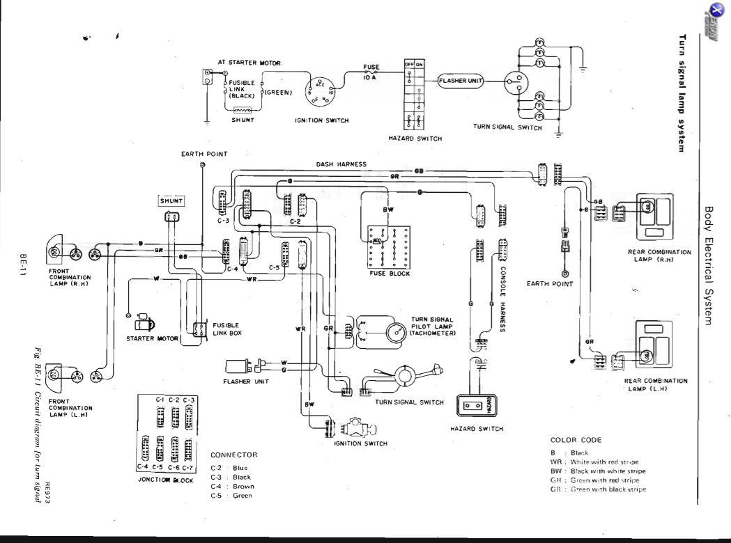
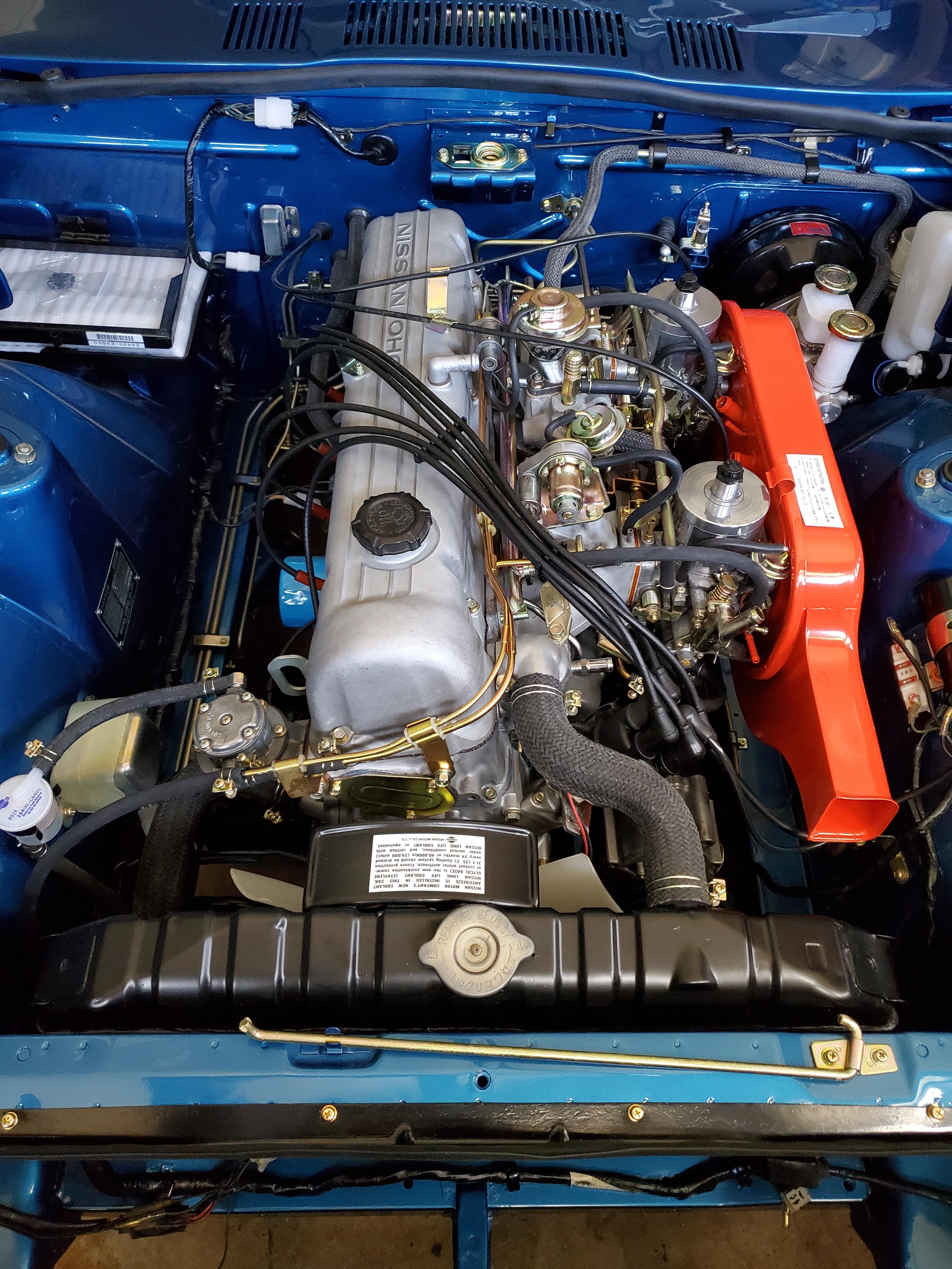
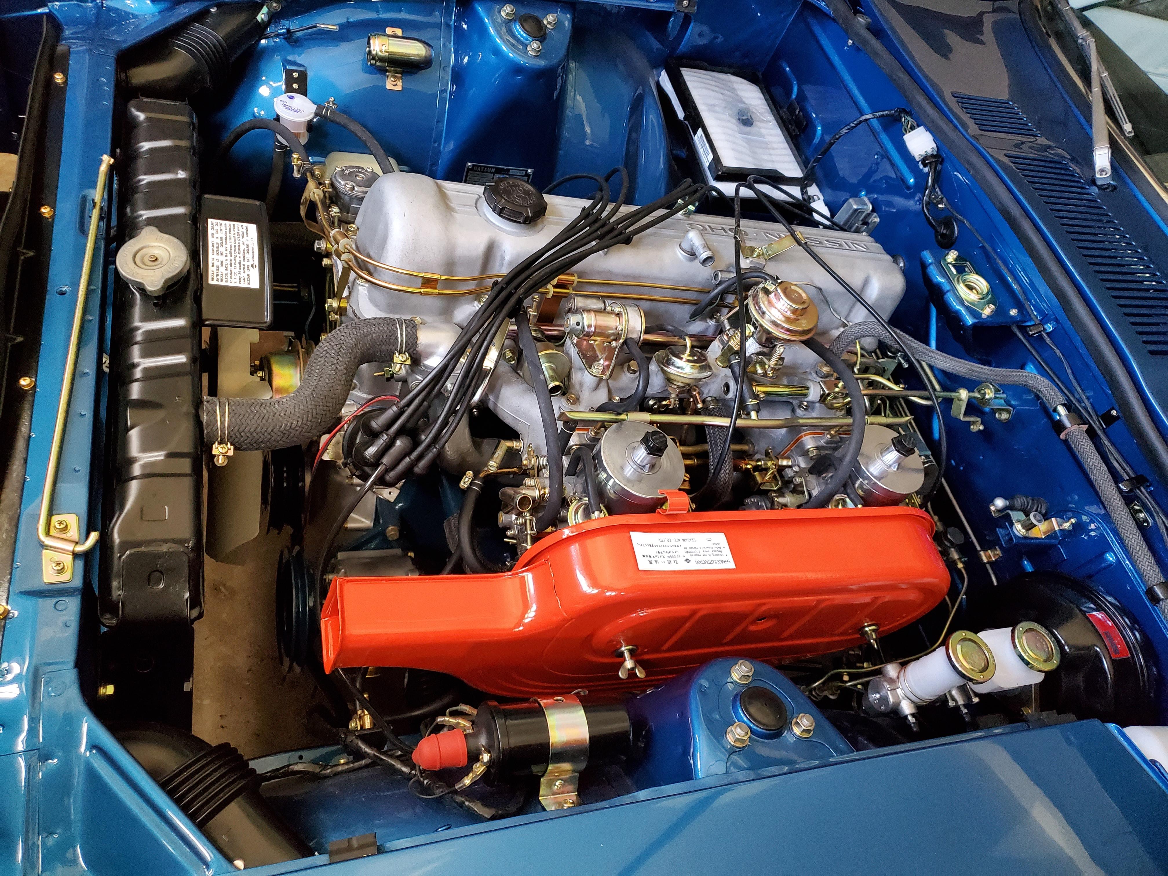
2 points2 points2 pointsI think I have 3 covers and I hardly ever use them, when I come back from a drive or a car show the Z has a fine layer of road dust and brake powder on it. Unless I'm going to wash it again before I put it away I can't stand the thought of throwing a cover on it and rubbing all that abrasive dust in and causing all the micro scratches to the paint, that road dust gets on the inside of the cover so when I do put the cover on a freshly washed car it scratches the paint again. How often can you wash the car cover? Probably way over thinking it, so I end up putting the car away with no cover and when the car gets too dusty blast it off with a stream of water from the garden hose.2 points2 pointsToday, the Los Angeles Times newspaper ran a fun little story that the longtime Z owners among us may relate to. Here's the link: https://tinyurl.com/y2t4pxja Dennis2 points1 pointJust purchased my 72 and had every intention to rebuild the engine but with all the other items on the list of things to do I think I might focus my money elsewhere. Factory service manual says compression anywhere from 171-185. I did a dry/wet compression test last week on a cold engine and after reading a bit decided to do another compression test this weekend on a warm engine. Results are as follows: 6/22/19 1 2 3 4 5 6 COLD ENGINE Dry 165 150 170 165 150 165 Wet 190 175 190 190 175 190 6/29/19 1 2 3 4 5 6 WARM ENGINE Dry 150 150 160 165 155 160 Wet 175 175 180 190 180 190 All plugs were pulled and the same compression gauge was used for all results. Started with #1 and worked my way back. Throttle wide open, and cranked about 10 seconds watching the gauge through the windshield. Wet tests were done with about 5ml / 1 teaspoon of oil in each cylinder. Based on the results it looks like the rings just seem a bit worn but all compression numbers are pretty close? The car doesnt smoke but feels a bit sluggish. I'm used to riding motorcycles so my sense of speed might be off. The car is definitely running rich based on the plugs and I've had a leak in the exhaust (which after running the tests I believe is in the exhaust manifold). I should mention that the car has been sitting 10 years so it definitely needs everything gone over. I'm thinking instead of rebuild, just do a full tune up on the thing and focus on all the other bits (gas tank, brakes, suspension, rust repair).1 point1 pointI have a tight fit indoor cover on my 370 (when it’s clean) and it is wonderful. Washed in the machine no problem.1 point1 pointFirst, the FSM clearly identifies two ground points for this circuit. One is in the engine bay, and the other is by the taillights. They are identified at Earth Point. Let's talk about theory of operation as designed. When the turn signal switch is moved up or down, it completes the circuit for the right or left side respectively. Using a positive to negative flow, we can trace voltage from the battery, to the starter, through the black fusible link, through the shunt, through the green fusible link, through the ignition switch, through the fuse box, through the hazard switch, through the flasher relay, and to the turn signal switch. After the switch, you just have the bulbs, ground, and back to the battery. As current flows through the circuit, the bimetal strip in the flasher relay heats up (power= current x voltage). Due to the nature of the bimetal strip, the heat causes the strip to move away from the contact, and that opens the circuit. The strip quickly cools down, and it makes contact again, heating it with the current flow. So, since you said the blinking speed did not vary with the engine speed, let's break this down into the elementary factors of resistance, current, voltage, and power. The resistance is primary from the bulbs. It can be considered constant. The current that causes the bimetal strip to heat up is voltage divided by resistance. This gives us two things to check in this circuit: The voltage in the circuit: Measure voltage to ground while the turn signals are operating and see if there are voltage fluctuations. Higher voltage would, in theory, give a faster blink rate. The condition of the flasher relay: See if the hazard lights exhibit the same behavior as the turn signals. If they don't, swap the two flasher relays and see if the problem follows the flasher relay.
 1 point1 pointRoy's into stump broken horses now but i could find something for you and your camera skills. Skinny jeans...they make the "wheels" look bigger.1 point1 pointDo a complete tune-up including valve lash. Your compression. #s look good for an engine that has sat. The #s will improve with mileage and a valve adjustment. After adjusting the valves, start it up and verify the cam is getting lots of oil.1 point1 pointJust get some run time on it, agree with Patcon, the numbers can improve with use as the rings get use, carbon gets burned up etc...1 pointI don’t recall bottoming out at any time. May be just a bad seal or something. The only way I found out, there was a rattling sound coming from the strut at low speeds. I’ve never blown a strut before, at least not that I knew of......I’ll replace both rears with Konis....don’t think Tokicos are available anywhere.1 point1 pointThe lower front end parts are different on a 280z but with an airdam they look like a 240z. The bumpers are different and the tail lights and front turn signals are different. The rear tail lights are the only real difference if you try to make a 280z look like a 240z. I agree with Av8ferg above! Since your in an apartment then I would try to get the best 280z you can that actually runs and drives. Don't buy a car that "runs & drive" but hasn't been driven regularly. Many times people get these cars running again to sell, but they can have lots of problems that can be frustrating to diagnose. The S30 market is very hot right now, even for the 280z. If you find the right car you need to be prepared to go look at it and buy it if it's the right one. If you can reach out to some members local to the car or local to you would be a good way to get educated and help you sort cars. You can also post up cars her for us to critique1 point1 pointYes, lines are the same. Tail lights and front turn signals are different. Badging is slightly different too. I’m doing the same. I’m going with 240 bumpers and front turn signals with a front xenon air dam. Custom interior inspired by the 240 diamond vinyl pattern. The average person can’t really tell the difference between a 240. and 280z. Bumpers are the big indicator. Sent from my iPhone using Tapatalk1 point1 point1 pointSo basically, you chose the skinny jeans (black one) over the baggy jeans (BRE) for your Cover. I've got a medium size cover from Costco that's just a little too big but it does the trick for my fashion sense. And, if you need any help on your rental, My buddy Roy Moore and I will be glad to help....?.1 point1 pointGot the air cleaner back from Powder coating. Installed loosely just to see how everything looks. Meant to comment on the wires above. I thought that I would need to make a new radio and antenna harness after pulling these two cables off of the dash harness. I lucked out however, as these were the cables that were the original radio leads. Somewhere out there is an original radio with the cables cut off. The new OEM radio just plugged right in making things easy.
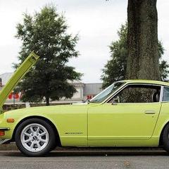
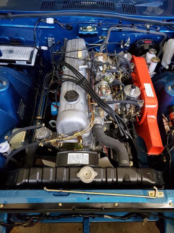
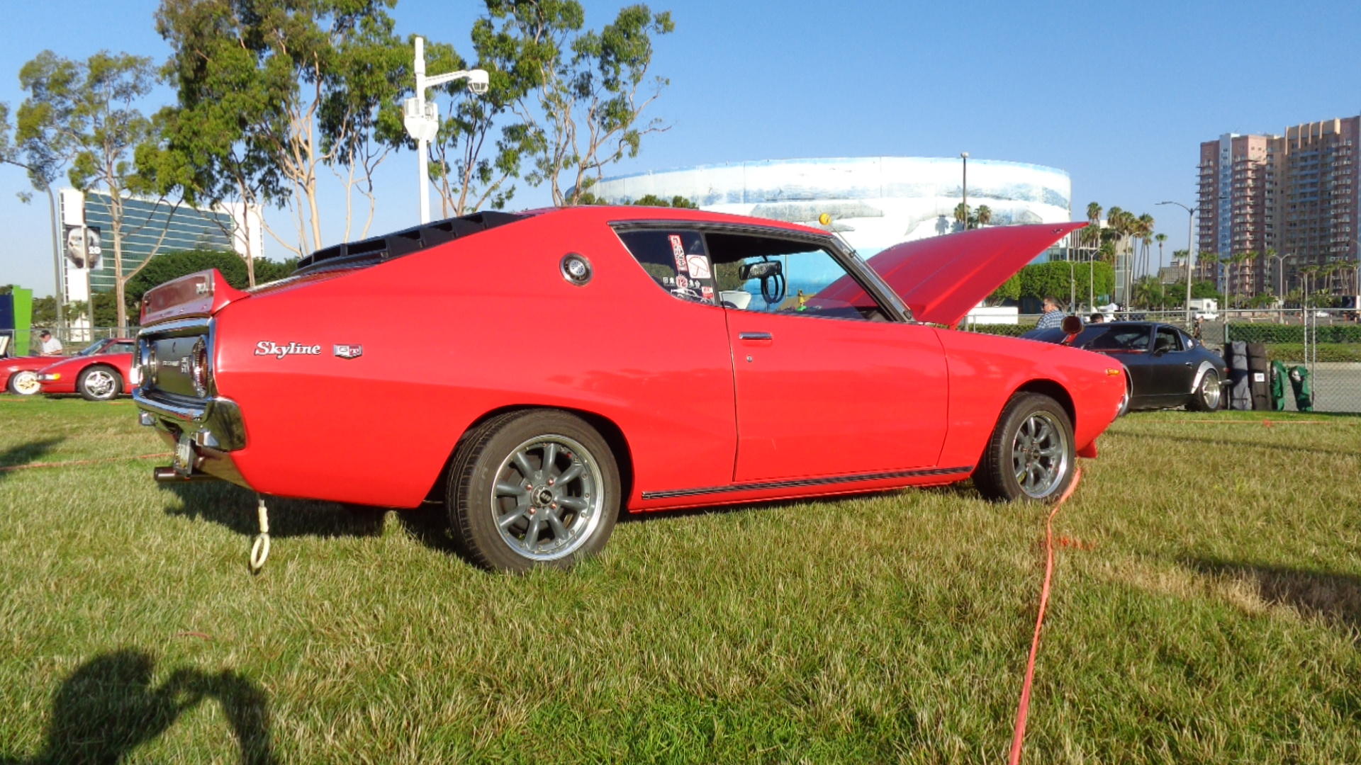
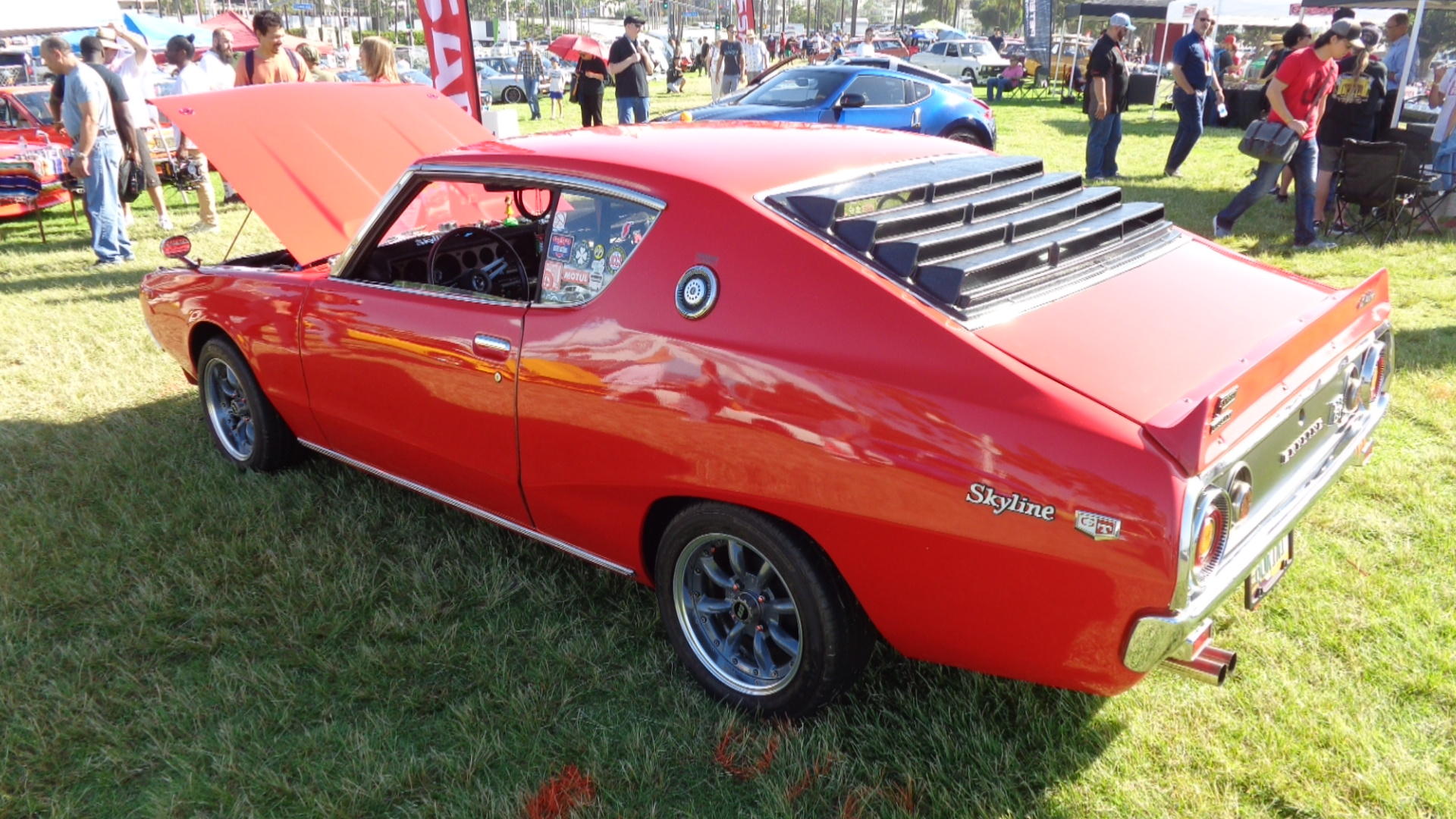
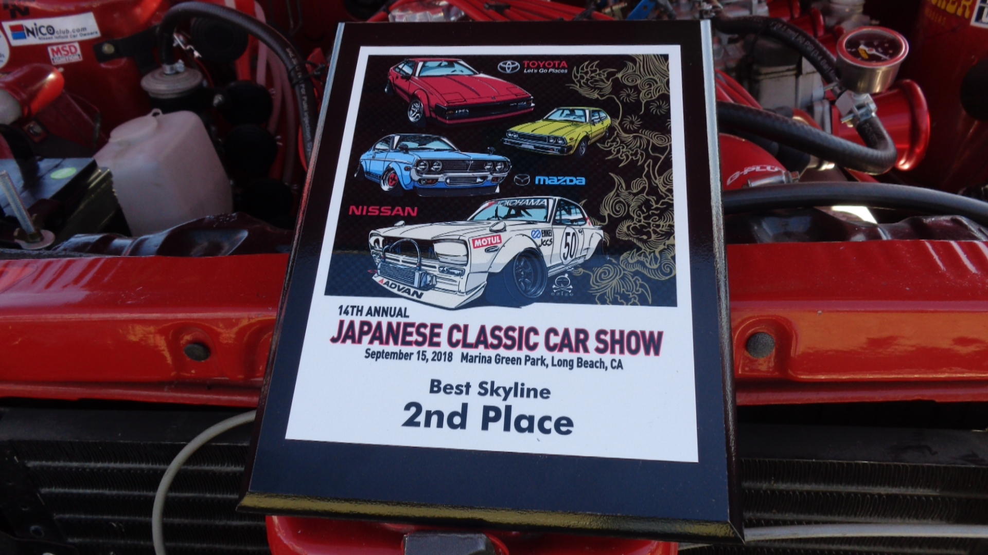
 1 pointI don't know the secret code to get a comment out of moderation there, either. On the other hand, I only tried once and figured that the moderators don't try or don't care about allowing posts outside of a select group.1 pointYou know I had to chime in here. Still amazes me that people are promoting the technically inferior SUs over the Flat tops, which are stock for this vehicle. I think most do not realize the advances that were incorporated into the flat tops that are not on the SUs. The flat tops feature 1) factory aligned needle and seats 2) a visible glass float bowl level 3) Anti-stall fuel rich mechanism 4) multi-point adjustable fuel mixture screws 5) fuel pump accelerator. I would bet that most who are promoting the SU’s are unfamiliar with these features and have no clue what I am talking about. Personally, this car is about as good as it gets…I even love those hubcaps! OK, no more carb comments from me…I will go back into hiding. I tried to post this comment on the auction site, but looks like they will not allow it....perhaps it is too inflammatory. Maybe I should try to sanitize it and then re-submit.1 point1 pointJust came back from the 14th 2018 JCCS at Long Beach Ca. It was a 500 cars show....WHAT a turn out.Won 2nd Place in Skylines.The 1st was a Hako.


 1 point


Important Information
By using this site, you agree to our Privacy Policy and Guidelines. We have placed cookies on your device to help make this website better. You can adjust your cookie settings, otherwise we'll assume you're okay to continue.