Leaderboard
-
Jeff G 78
Free Member3Points3,007Posts -

wheee!
Free Member3Points4,607Posts -
psdenno
Free Member3Points2,632Posts -
Captain Obvious
Free Member2Points10,080Posts


Popular Content
Showing content with the highest reputation on 04/18/2018 in all areas
-
I love seeing the Z love on TV, but personally, I liked the old days of cheap Z cars. Everybody who owns a ratty Z now thinks they are sitting on a gold mine. The days of building an affordable Z are unfortunately over. I think that the skyrocketing Porsche 911 market is creating the huge demand for Z cars. Those who can't spend $50k for a 911 are willing to pay $20k for a decent Z car.3 points
-
3 pointsTruck transport to my house is $23,000 US (Mark’s Midnite Transport Inc). So I guess I owe you $2000?? We have a deal? PS: I’ve used this company before and I highly recommend them! [emoji6]3 points
-
I think the closing statement by the owner as he does his test drive with the windows rolled down at the end of the show sums it up nicely. "I love the smell. I'm sure it's not good for me.". Dennis2 points
-
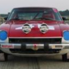
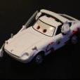
The Art of the Z -- running down Godzilla, no less!1 point
-
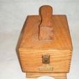
1 pointgot the new horn button in today, did not realize there was an "aftermarket" vs OE, looks very nice, but no foam more like a hard plastic interior, NO WAY the inner ring part will break on this. So if you are ok with it not being exactly OE I suspect it will not suffer from the same defect the OE has about cracking. I got this off ebay, later found on MSA and noticed there is a huge diff in the price of the OE and after market, like twice as much. I was a little worried that the new one I was getting may suffer the same fate esp if its NOS, but that is not the case with the aftermarket copy.1 point
-
Things are still happening, and FedEx delivered some goodies today. Hoping to get at least parts --if not all of it -- in epoxy this weekend or next! Sent from my SM-G950U1 using Tapatalk1 point
-
1 pointWow... Look at the time. I need to head to the beer fridge now! Mine draws 3.2 AAC.1 point
-
1 pointWell I've never held an early tach with my own two hands, so this is mostly engineering speculation, but I would go something like this... The early tachs ran the coil current to the tach. And (now that I've seen that picture), I would surmise that they used an inductive pickup for the tach to sense the ignition pulses. Just like the inductive pickup on your timing light. It senses current that flows through a wire, and just like your timing light, it does that by wrapping a "sensor" around the wire your interested in. Also the same as your clamp-on ammeter you use for house wiring to measure the current being drawn by your beer fridge. So that thing on the back of the tach is the inductive pickup, and the white wire running through it is the one being sensed. So now the real guessing starts... I'm guessing that the inductive pickup on the back of the tach is relatively cheap and prone to crosstalk and/or wave shape. I'm thinking that there may have been some crosstalk from the portion of the wire NOT looped through the sensor that was messing with the sensing of the wire that WAS looped trough the pickup. So by moving the loop of wire farther away from the pickup, it reduced the crosstalk or changed the wave shape just enough that the tach likes is better. Kinda hard to do that kind of analysis with no parts like that here though. Could be totally off, but until someone has something better......1 point
-
1 pointBack then some of us got hooked on Z's before we even drove one. To that end, we did whatever had to be done to get one ASAP. I payed 73 sticker price for a used 71 in 73. One of the best decisions I ever made.1 point
-
1 pointInteresting to see the list of dealer "add-ons" that jacked the price nicely. Goes to show how hot sales were for the Z in those days. Pay over sticker price, pay for dealer add-on items, or go on a waiting list to get a bare bones model. I was one of the "pay over sticker price" buyers in 1971. Dennis1 point
-
Without concern for originality, the "right" thing to do is install a new fuse block with modern ATC fuses ALA what MSA sells, or make a new one. Maybe a couple of more circuits so adding a couple of basic things isn't an effort in futility. I'm trying to get this thing reliable and mobile, restoration comes later. Maybe really later.1 point
-
Very nice piece of kit, but the dual exhaust pipe run doesn't add anything except excess weight. A properly sized single run seems much more sensible. I question whether that header would clear the LHD steering rack.1 point
-
If they stick out you can count on them touching, normally at speed over an abrupt depression. Could be enough to take the paint off to the metal or cut through the sidewall. Trust me I've been there.0 points