All Activity
- Past hour
-
 A work colleague of mine and I spent about an hour yesterday getting some video of the 240z I restored (got it on the road on Dec 31 last year). Unlike me, he has skills and talent for editing and creating videos. Have a look! https://www.youtube.com/watch?v=nQ3ieeuqjwI
 -
 Yep, I read that one and that is what caused my post. I have the oil pan from the turbo motor, and I have the oil pan from the original L24. I can use either, but they both need re-habbing before I can use them. I didn't want to have to re-hab both of them at this time, but I think that is what I'm going to do, as they will both need to be done at some point anyway. Since I have the pan out for cleaning up, I have the ability to modify/change/omit the heat shield from the turbo pan. Can you explain what part interferes with the header? I'm thinking I may be able to retain some heat-shielding of the gasket and still fit the headers? I'm actually considering just using the MSA header I have for now until I can save some more dollars for the ZStory headers and hopefully, the tariffs will expire as well! I've also read that the turbo oil pan may not fit into the 240 because of the sump being in a different spot from the 240 pan, and causing interference with the crossmember, but I haven't been able to confirm that either.
 -
 I found the post where I was experiencing this issue. https://www.classiczcars.com/forums/topic/63969-which-oil-pan-will-fit/?&_rid=2593#findComment-665907
 - Today
-
 I found some good pics, etc. of that booster here >> https://irate4x4.com/threads/ibooster-electric-brake-booster.394316/ Mounting: The mounting bolt pattern is 2.375" x 3.1875" square with a 2.5" center bore pass through:
 -
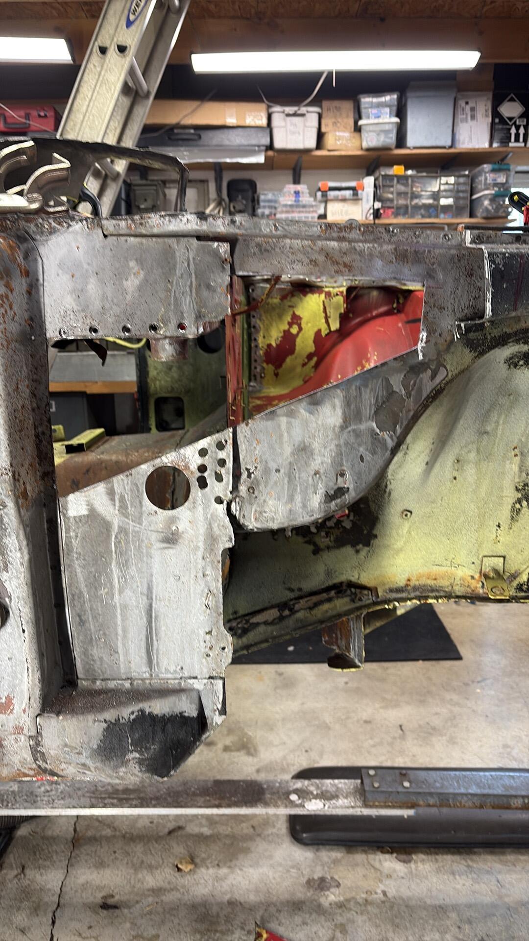
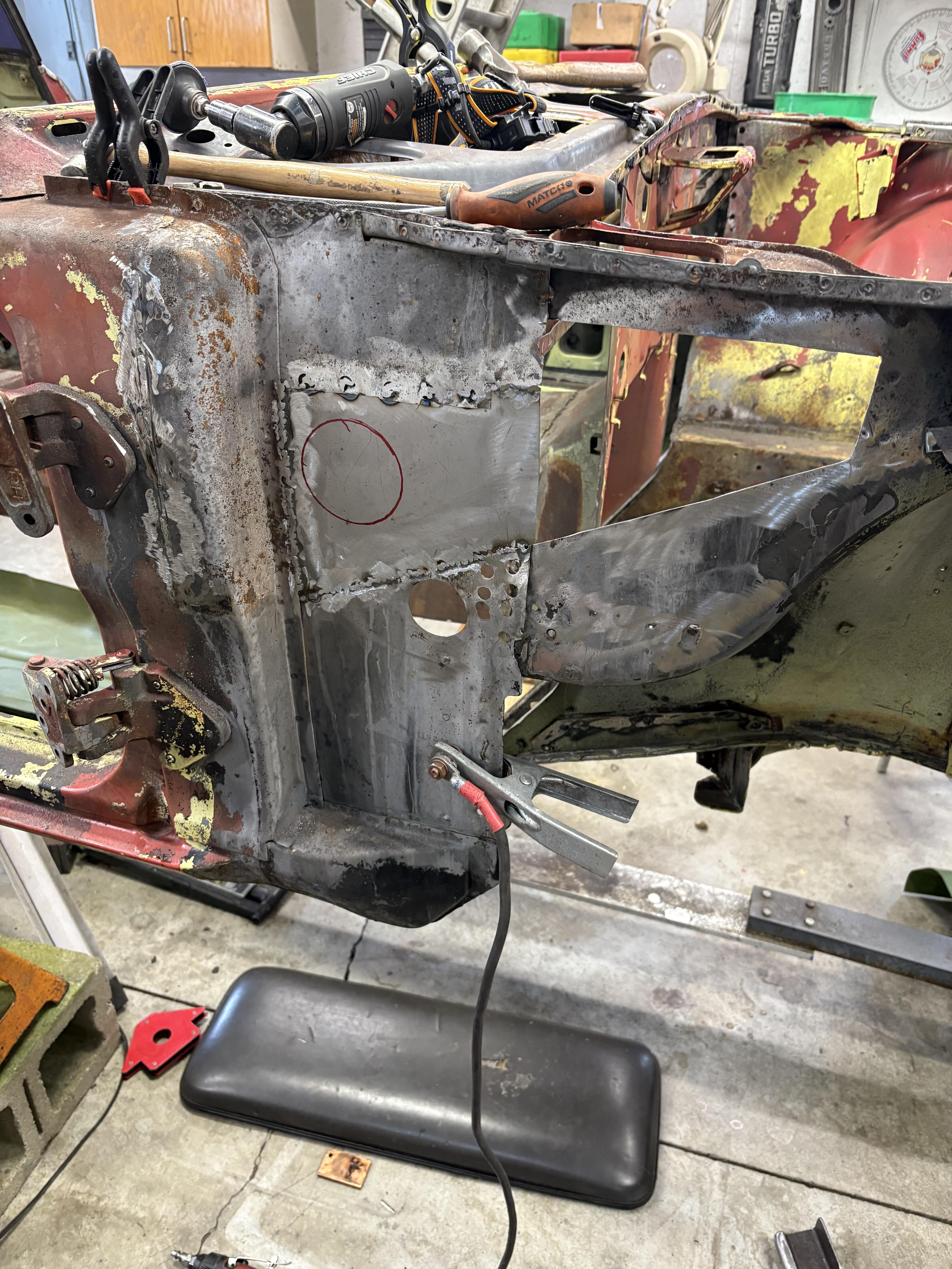
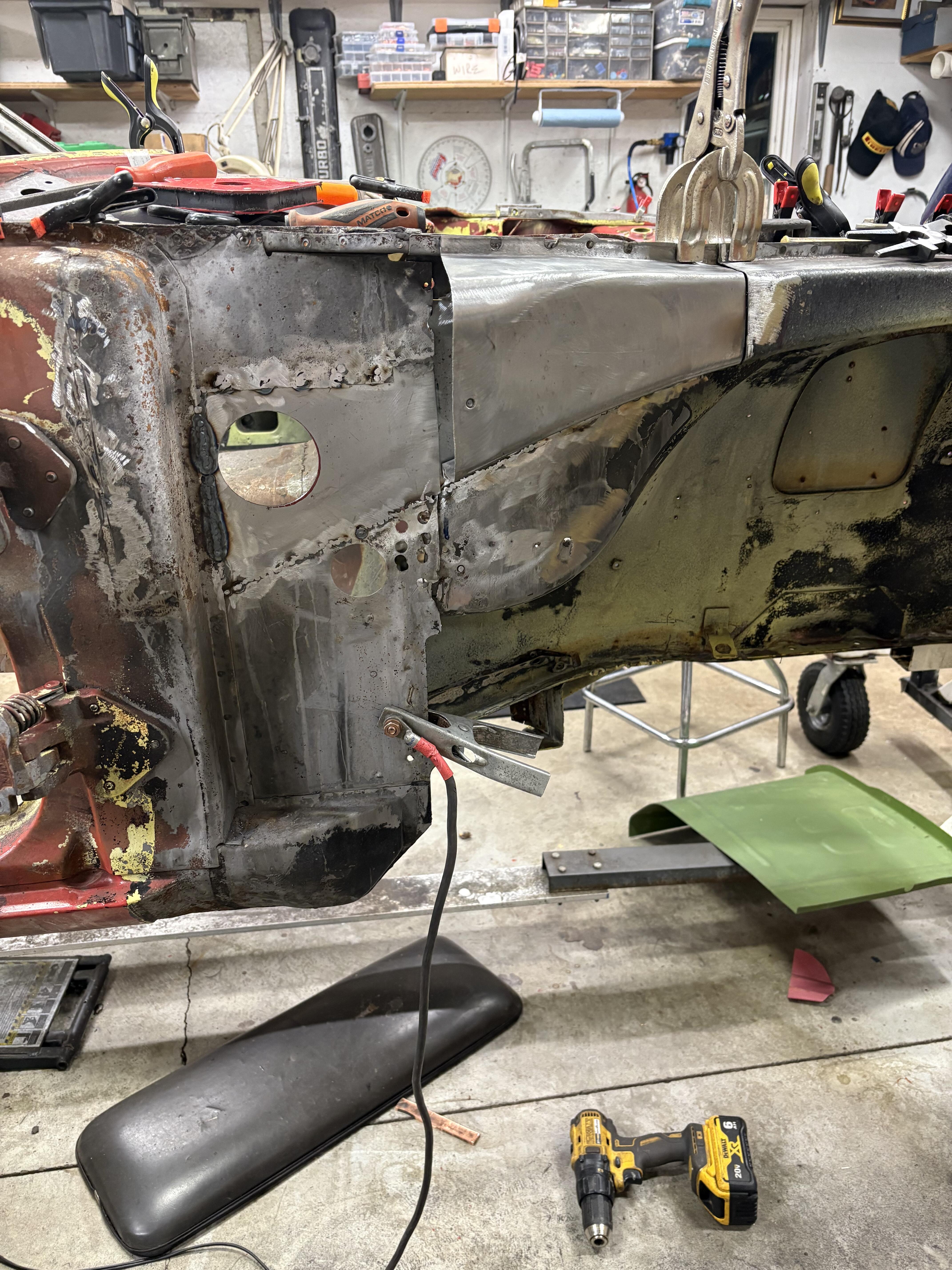
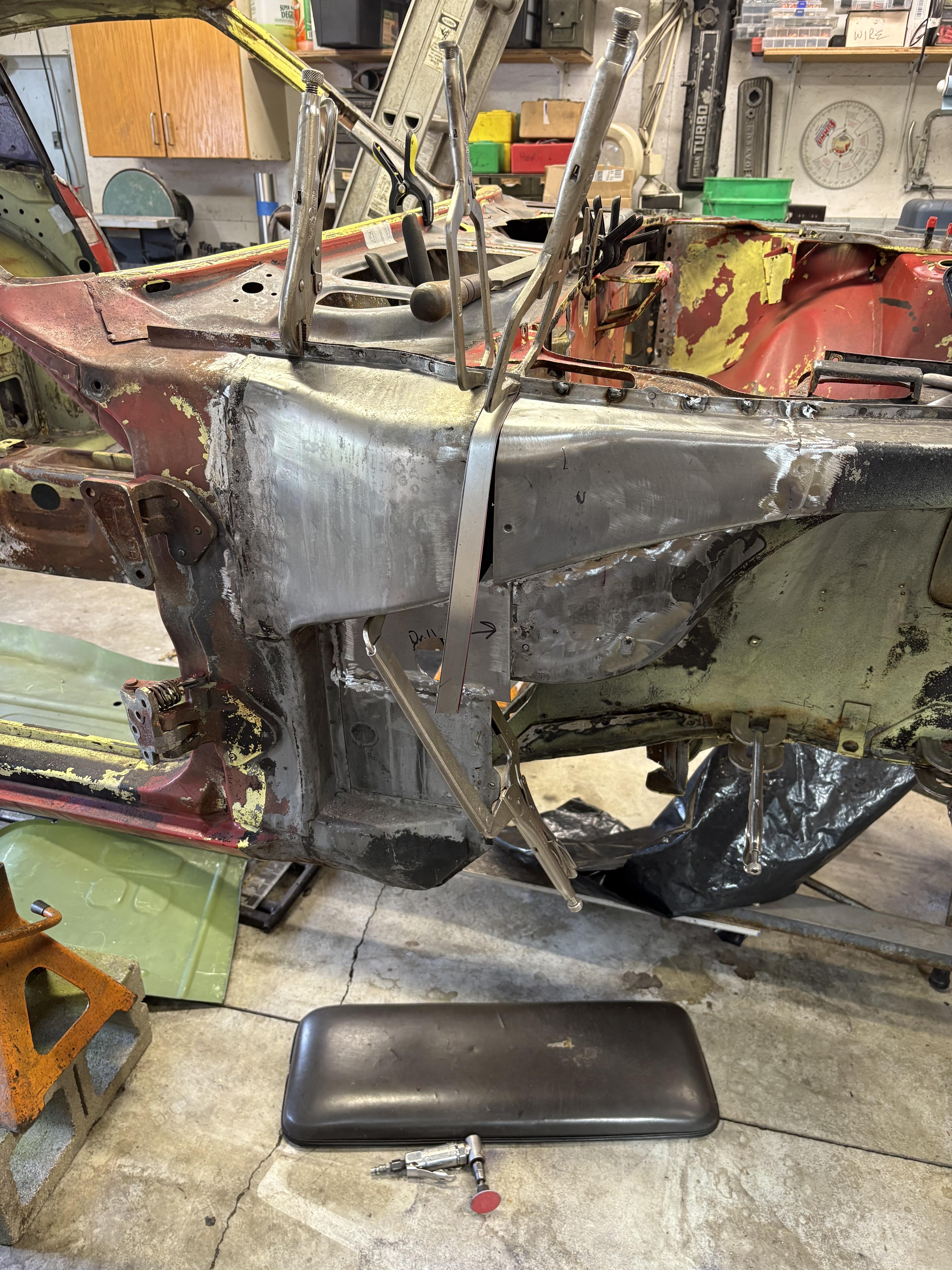
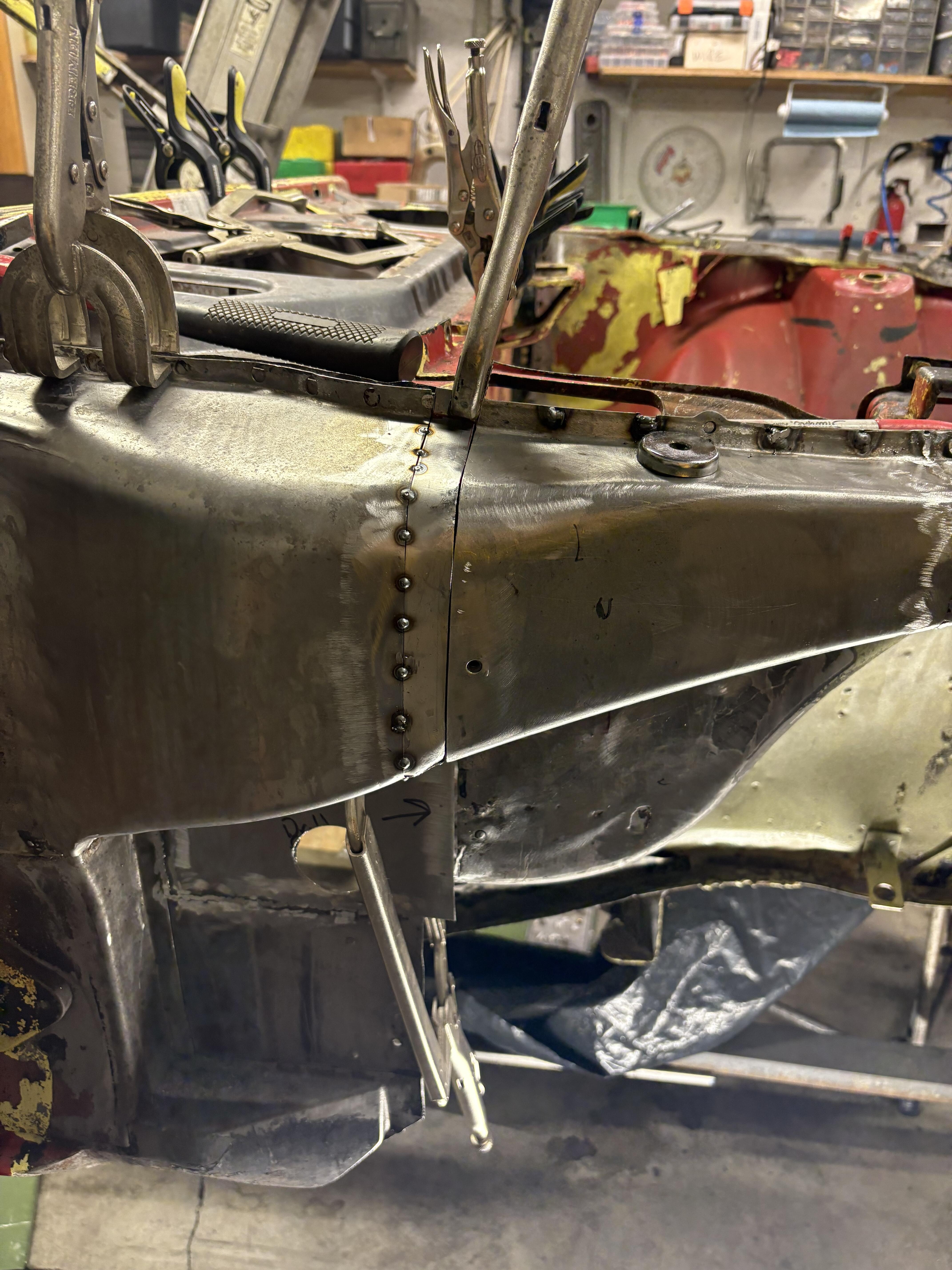
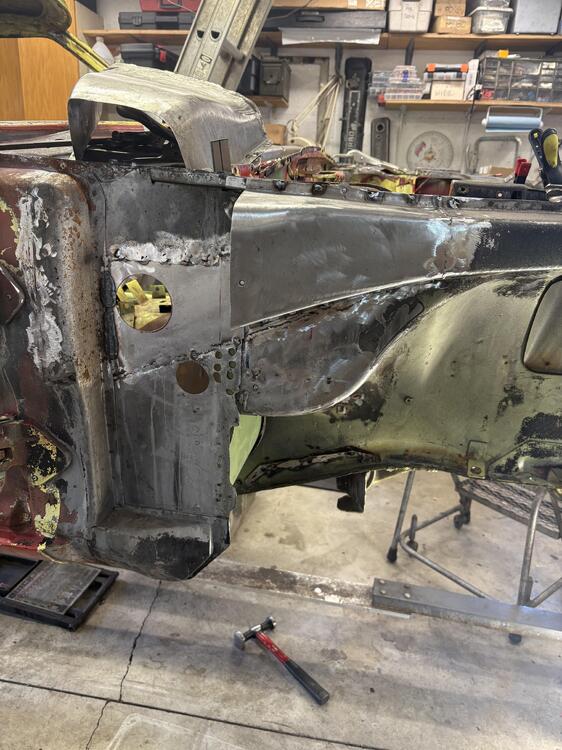
 Thanks for this latest photo essay. Lots of good insights here into how multiple panels come together in this complicated and structurally-important section of the car. You did some very nice work in forming the two big replacement sections for the upper frame rail. Can you talk a bit about how this was done? Also: What was the gauge of the sheet metal you used? In the 4th photo, there's what appears to be a right-angle drive power tool, with a 3" sanding disk mounted in the chuck. Is this your go-to tool for grinding welds? Who makes it?
 -
 Dou you have any spacers in the mounting hardware that can be swapped to the bottom side of the seat mount?
 -
 Looks like a bunch more room in there doesn’t it?
 -
Found it. So, this guy on Facebook posted these pictures. Apparently, he used a Bosch Gen 2 iBooster. The housing, I get the impression he found an open source file and 3D printed it. Here is what I have, he says it works better than his GTR brakes!


-
 The passenger side was exceptionally bad in this car relative to other sections . The car sat outside on a rotisserie for years on its side with the passenger side down . Probably gathered water from rain . When I finally dug into this I was grateful I had scrap pieces to do some of these repairs . Somehow I was missing a hunk that I had to make - but it’s was a small hunk . Removing the firewall and all its spot welds really tears up the kick panel . That and rust required some patching work to make the kick panel strong again . I probably will end up ordering the panel for under the battery tray from KF Vintage . I don’t think my skills are up to fabbing that panel .


-
Yeah, hopefully it should be easy to tell. In any event, it's got to be better than this!!! Hahaha!
-
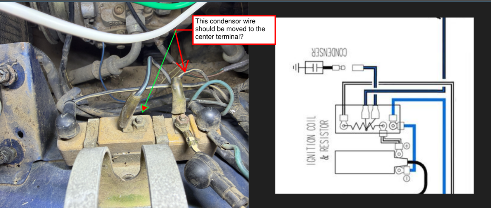
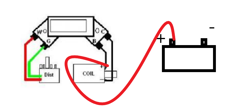
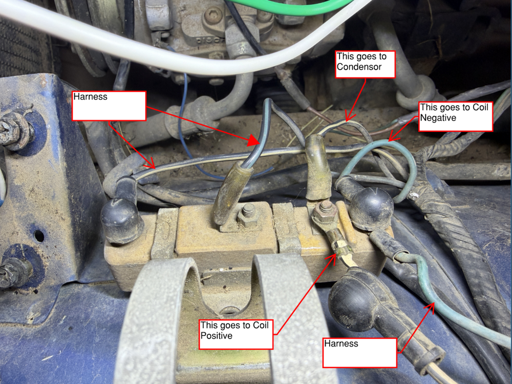
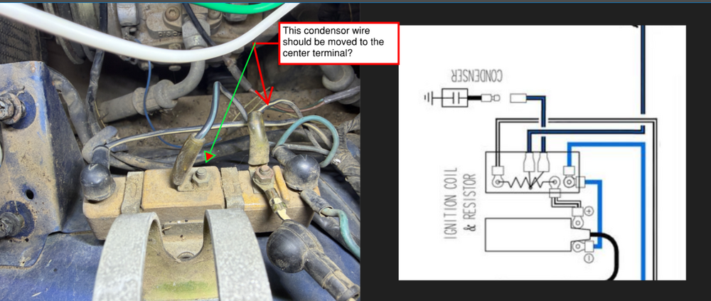
 It doesn't really matter which terminal has the condenser attached. It's there to stop electrical noise.
 -
Seat cover fit might suffer. In essence, you'll be increasing the height of the side bolsters by 1 inch. The centre panel of the seat cover would end hanging in space above the carved-out foam. Occupant weight will force the cover down onto the foam, but the look (baggy) when the seat is unoccupied might make you wish you'd never tried it. I suggest that you run the idea by an experienced auto upholstery pro before you break out the carving knife
-
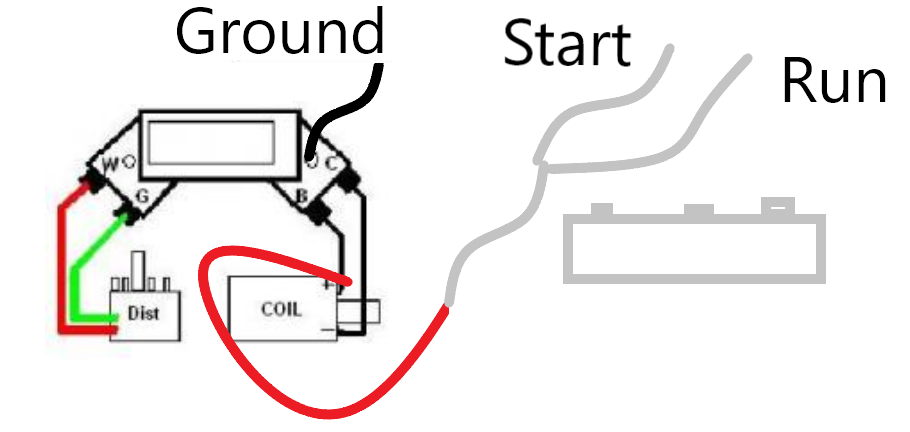
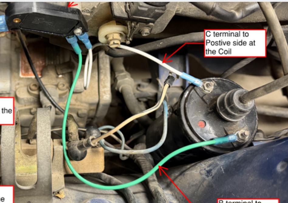
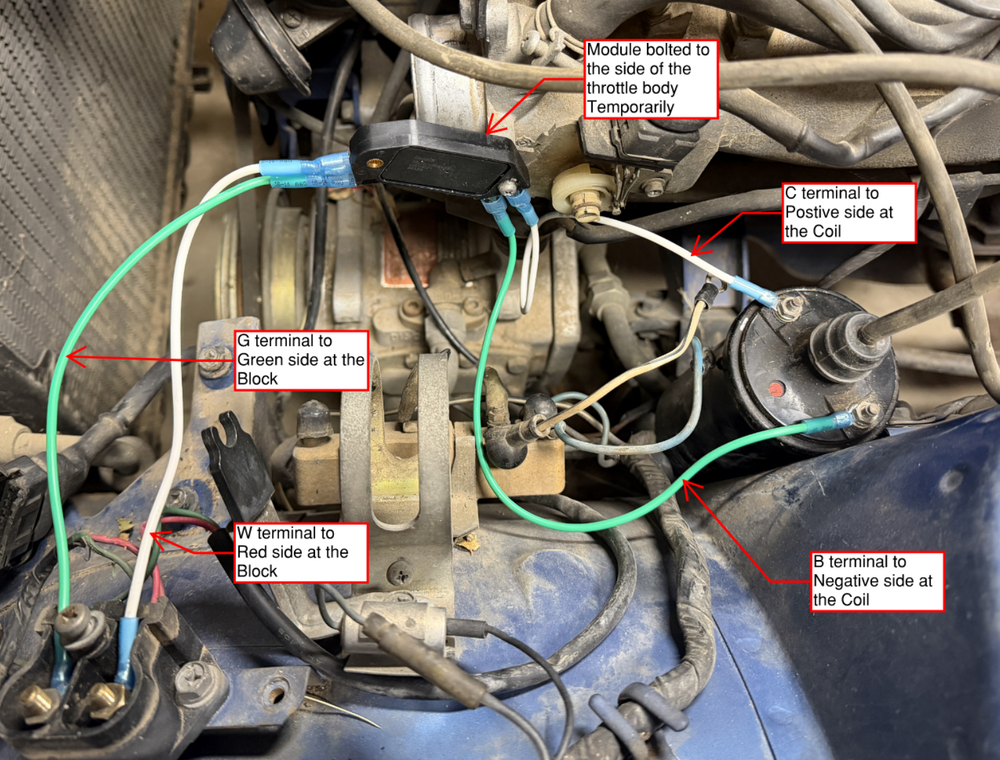
 This makes 100% sense. As far as the other questions When I tried it last week I had the coil wire attached and one spark plug lead with a spark plug at the end laid on the block, not the best I know. I was mainly looking for any indication to get moving in the right direction. The car came with an inline spark tool. I am cranking the engine with no spark plugs in the block. I am cranking with many full rotations as I am aware that I will only get spark as the rotor makes the connection. Am I missing something? I'm not a legit mechanic and this is the only way im aware of. Is there another procedure that I'm that Im not aware of? The old module is not installed. From the reading I have done, this is the way The module location is definitely temporary and is mounted through the hole with the large ferrule. My initial thought was to cut up the old module housing and is it as a heat sink or perhaps find an old heat sink from a PC. The PC option seems the best solution, but I haven't given it a ton of thought yet. I think they make heat sinks specifically for these modules as well. When you say this, it sounds like I will need it in the future? Is there a reason why I would leave it disconnected for now? Am I correct that the condenser is on the wrong terminal?
 -
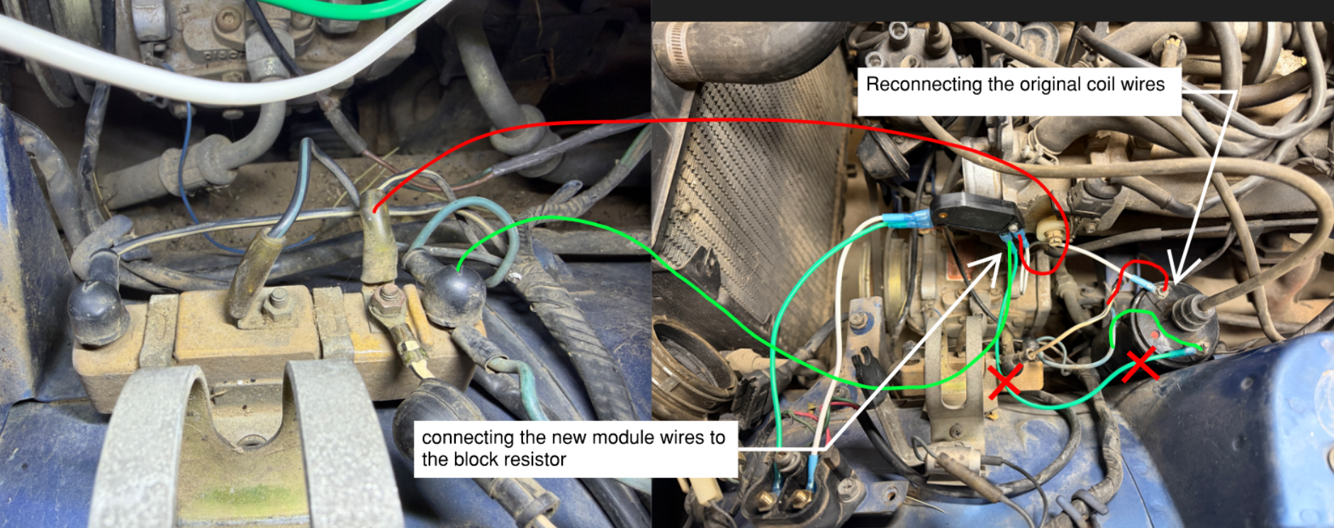
Just leave the condenser disconnected. You don't need it for now. You can also just connect both of the wires from the ballast resistor (the block) to the coil positive. You don't need it when you use the HEI module.
- Yesterday
-
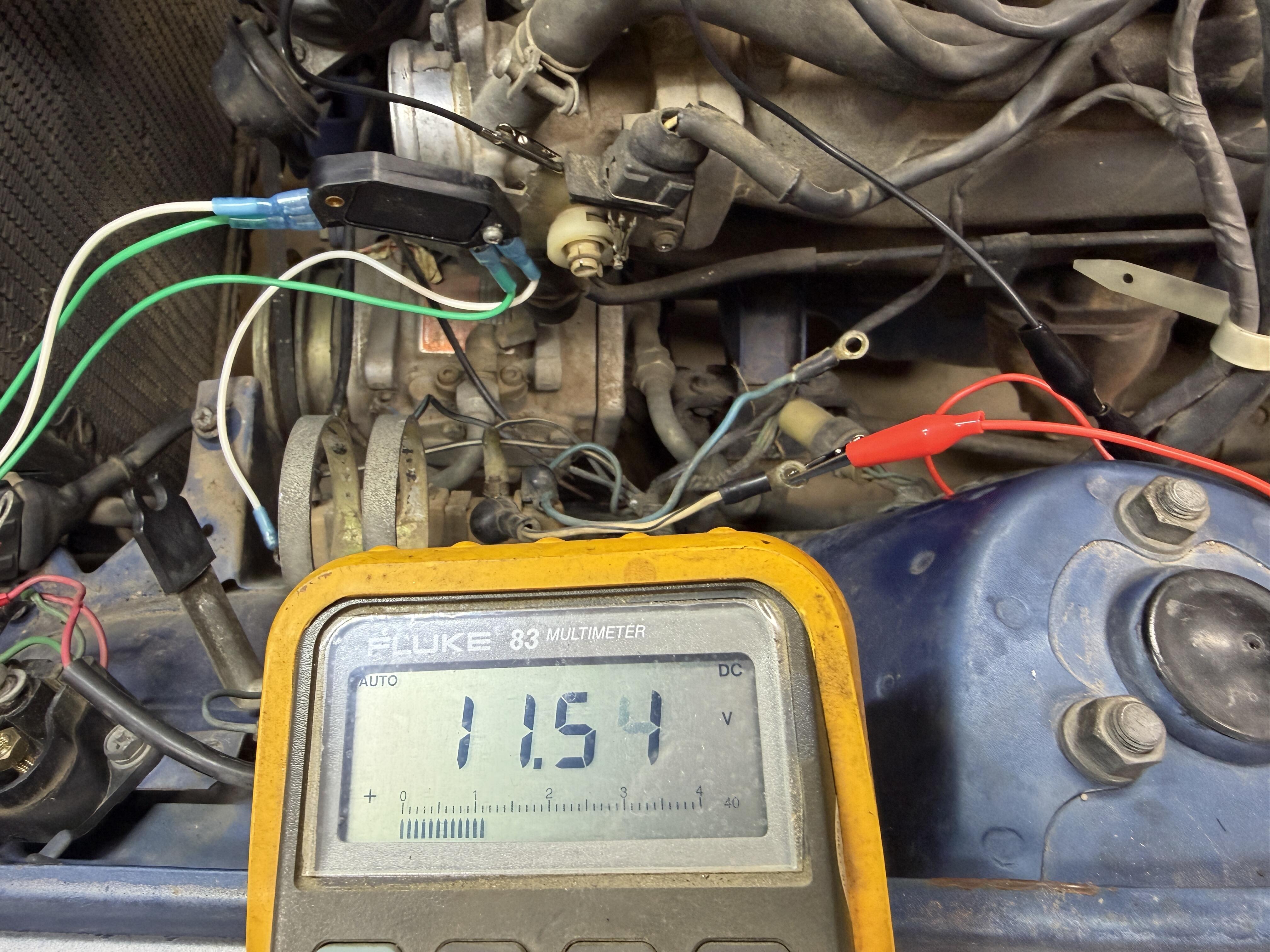
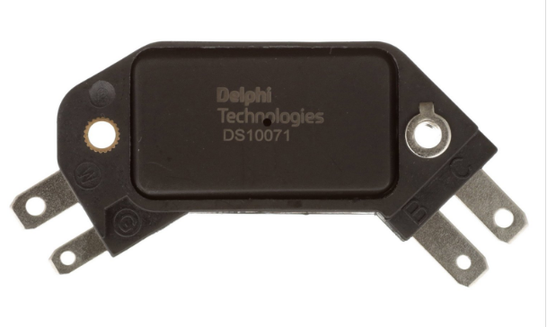
I would add some details of how, exactly, you are evaluating "spark". With a spark plug at the end of a plug wire, through the coil center terminal, with a spark tester...? Are you cranking the engine when you do this? Have you disconnected the original module by the fuse box or did you resintall it? And, or, but, I have noticed that you do not have any battery power going to the coil in your picture. You only have the coil connected to the module and no pwer to the module either. You need power to the coil positive terminal. Also, use your meter and make sure that the mounting screw of the module has a good ground. And make sure that it's the correct screw. Only one of the screws completes the ground through the module, it has a thicker ferrule. Looks like you have the correct screw but you might not have good contact through that screw head or where it seats on the TB. The TB is not the best place to mount it. That's where all of the coil current flows when the module is doing its thing. And, it you plan to run it for long you need a proper heat sink under the flat part of the module. It gets hot and heat will cause them to fail.
-
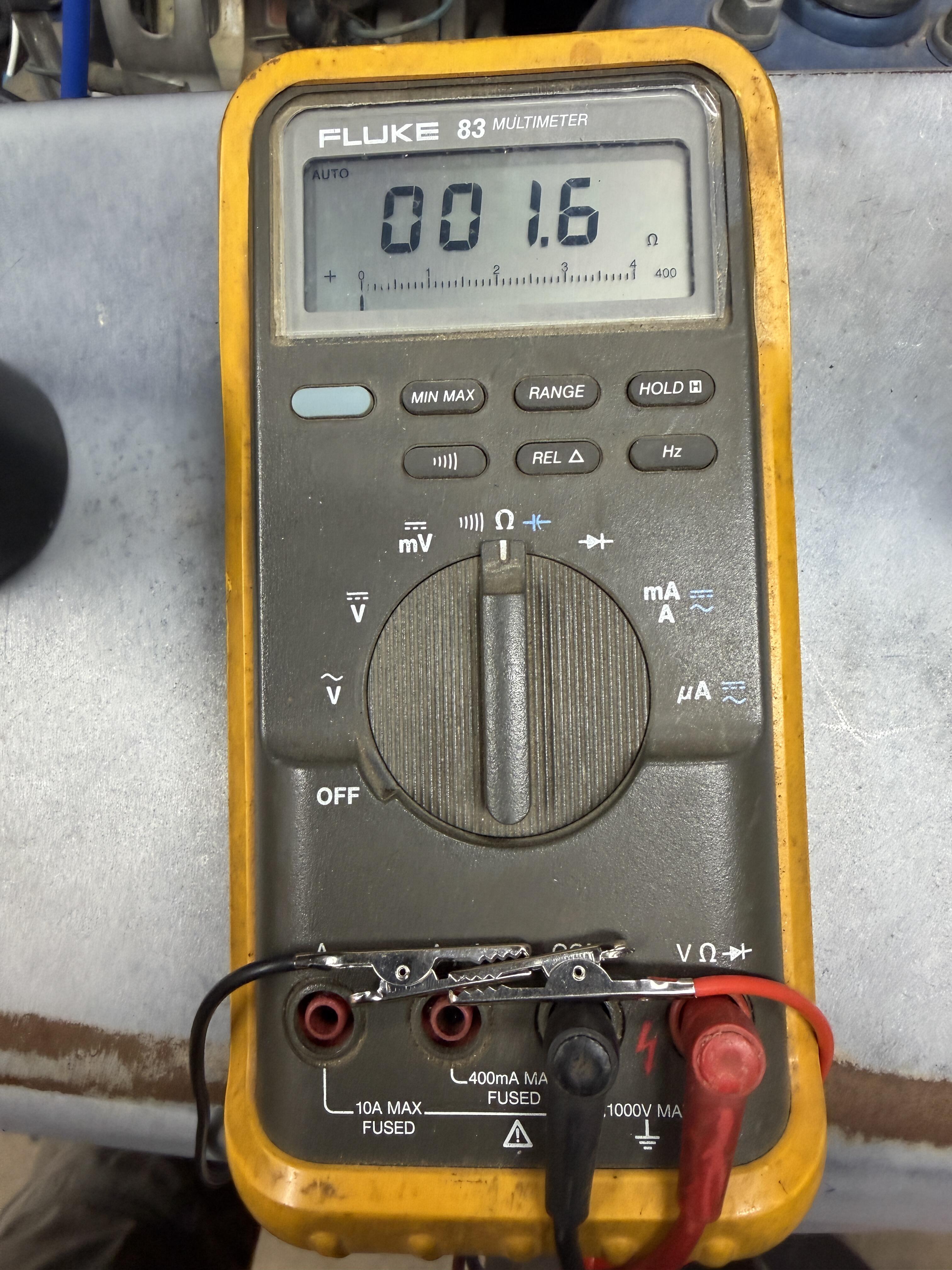
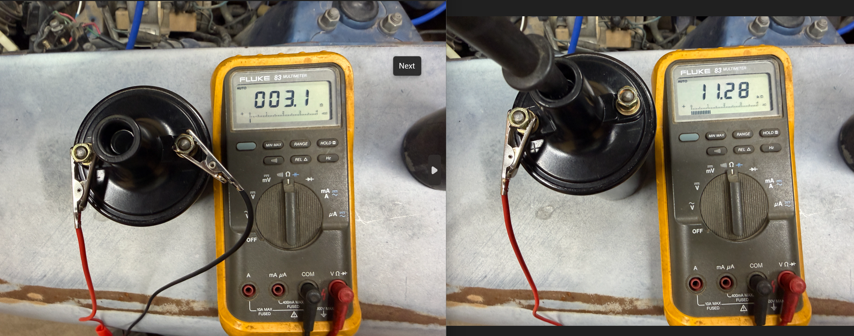
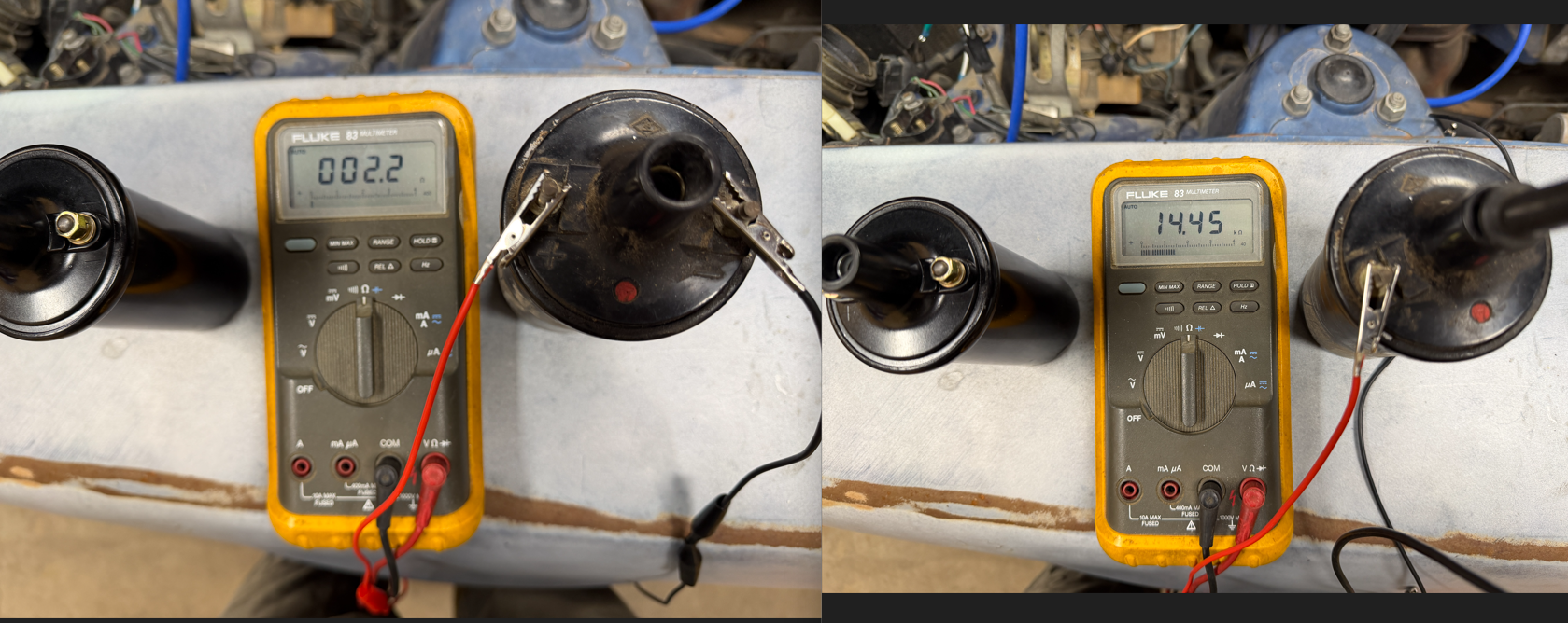
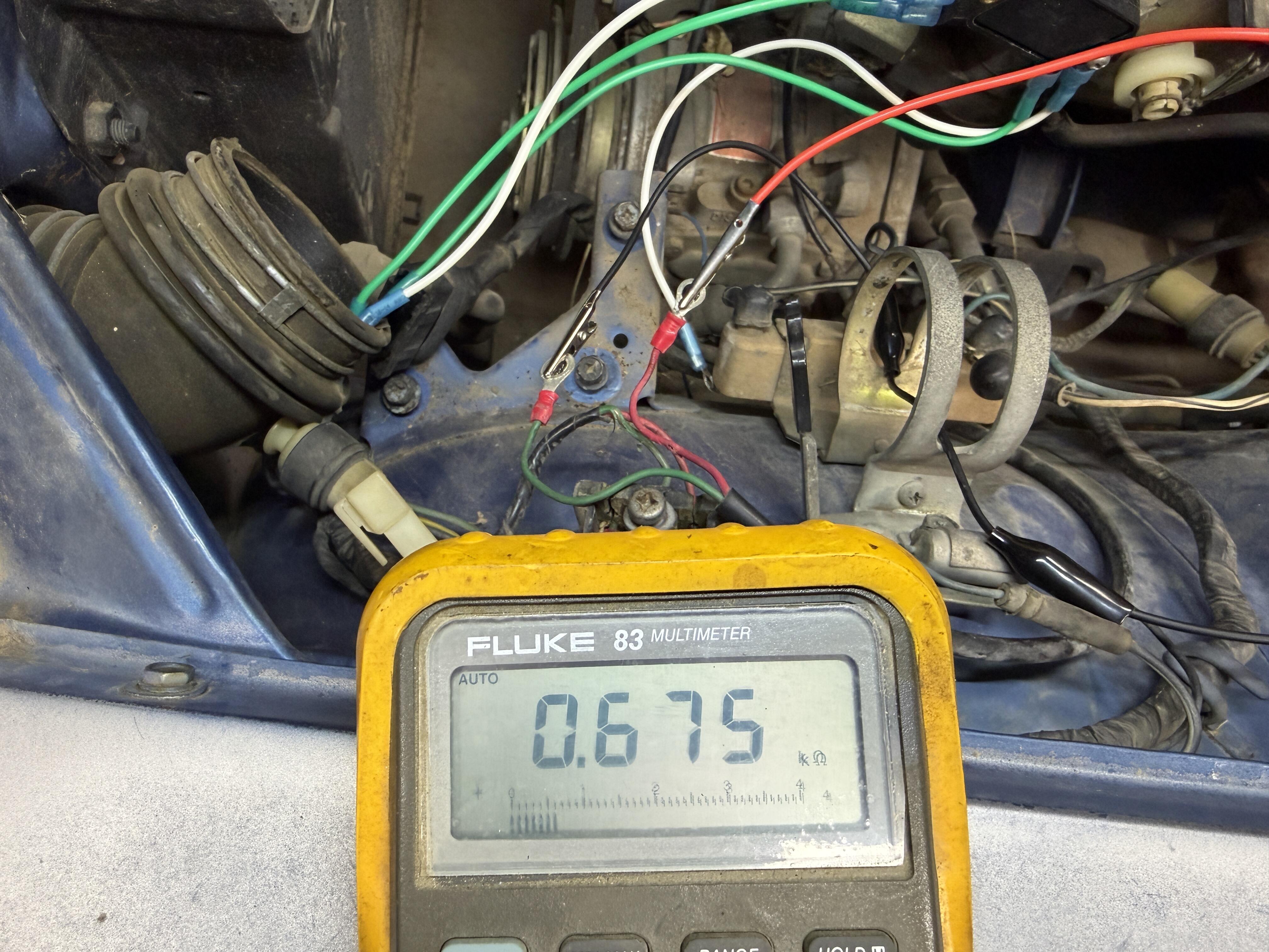
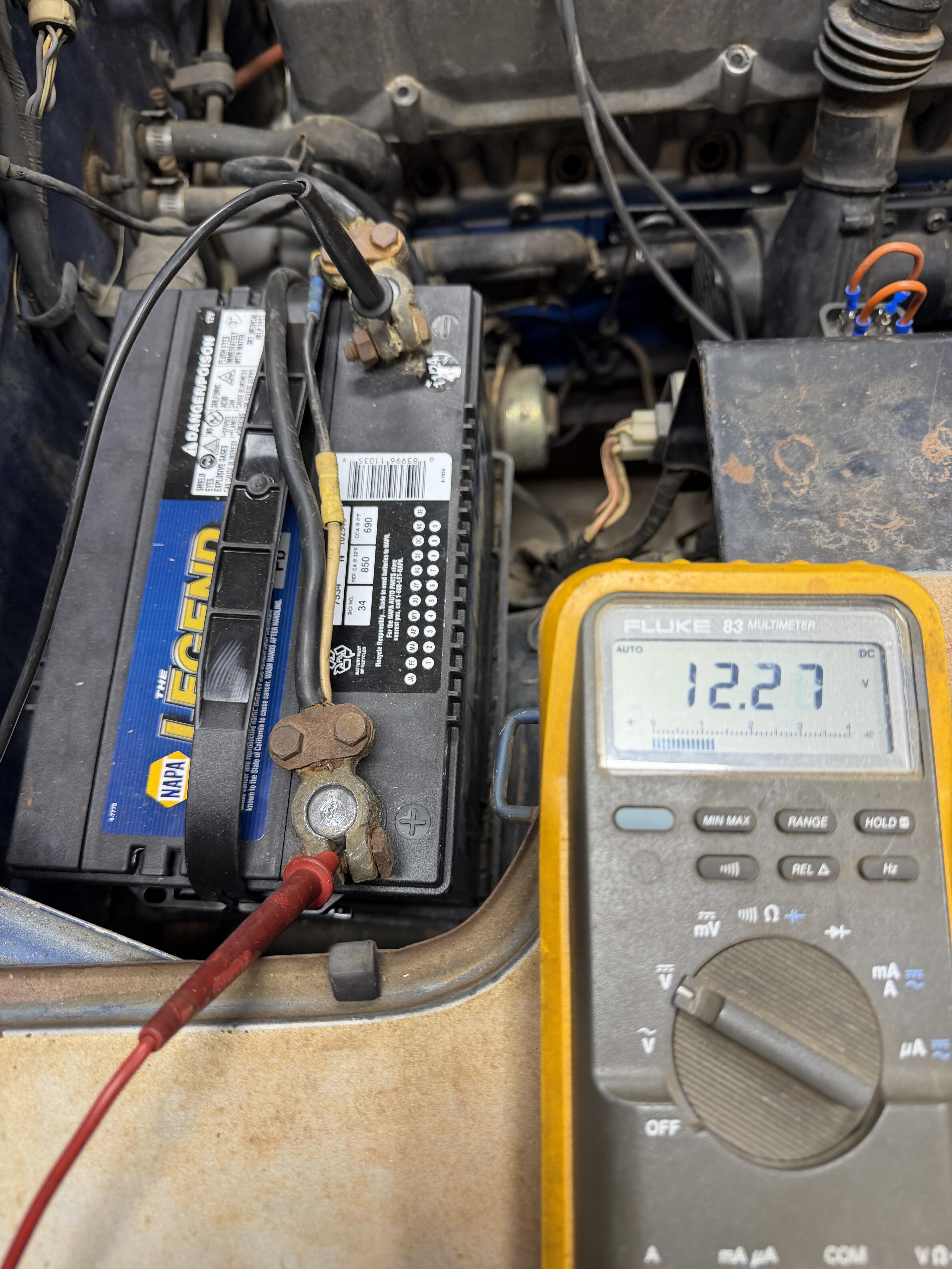
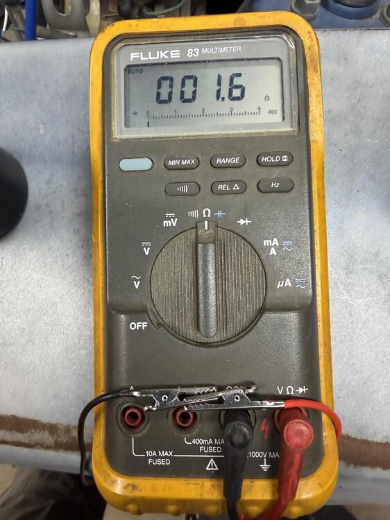
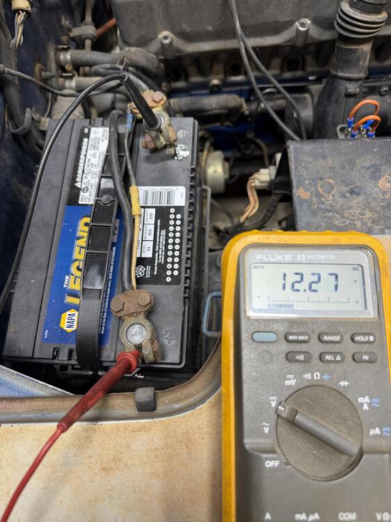
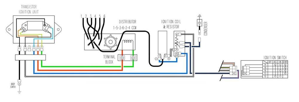
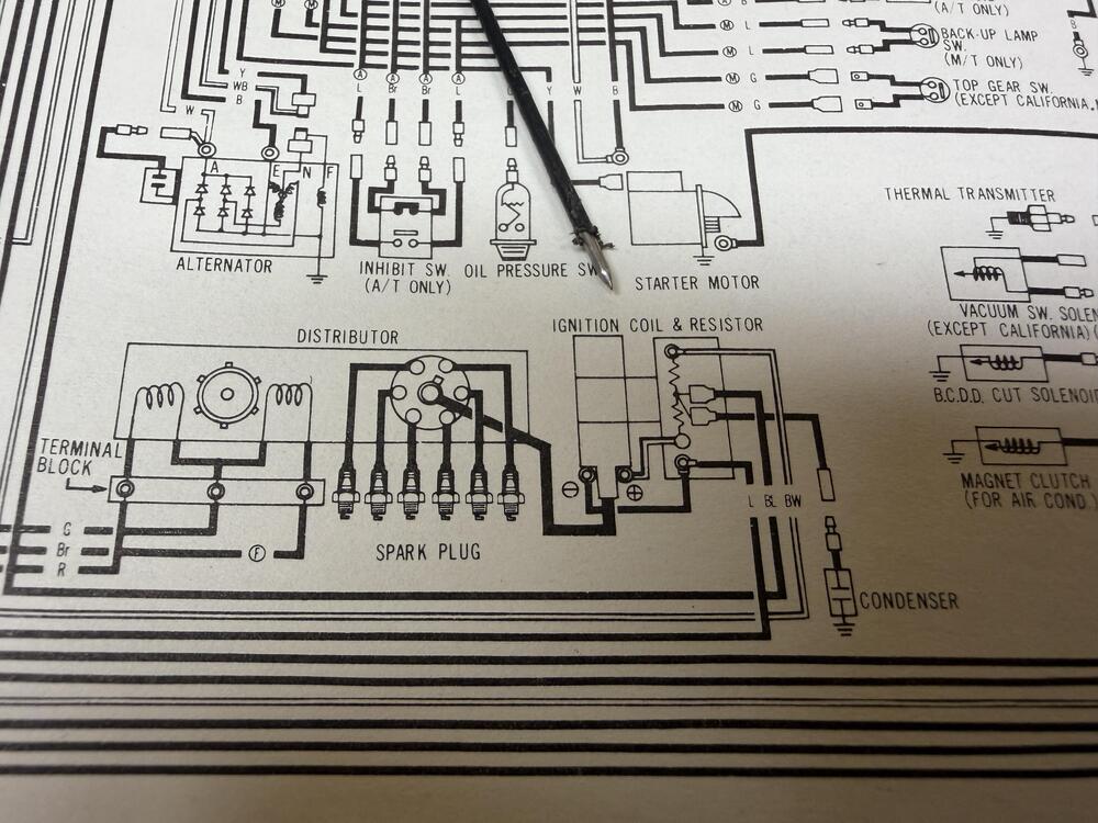
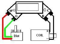
some new updates on my ignition woes and HEI module upgrade. Tested resistances on anything I currently have knowledge of. Near as I can tell, everything is as it should be. I tested both coils that I have using the method listed in the video below. I'm a sucker for detailed documentation and I had a hard time following some of the posts I found. So hopefully this will help others. The initial test was to test the resistance of the tester itself and it turns out mine needs a little recalibration. Not a huge deal as I understand that I just need to subtract the value from the readings that I take. It turns out that I am off by 1.6 ohms. It is a 30 year old meter though that I inherited from my dad. The readings on the new coil. 3.1 ohm (1.5ohm corrected) between the + and - terminals and 11,280 ohms between the positive and center. I purchased this (amazon) coil. It is suppose to be a stock replacement. Pretty similar readings on the old coil. I kinda figured the old was was good, but meh, why not replace it just in case. 2.2 ohm (.6 ohm corrected) between the + and - terminals and 14,450 ohms between the positive and center. Also tested resistance on the pickup coil in the distributor and it reads about 675 ohms. According to this post by Zedhead it should read around 720ohms. I feel like this reading is acceptable. I checked the voltage to the positive side of the coil with the ignition on (white w/ black stripe) as well as suggested by Fastwoman in this post. As well as the battery itself which is new but i have to get a charger on it. The voltages with the ignition on and off were practically identical. With that aside, im now looking into the wiring for the new HEI module. There are tons of articles on this, but it seemed hard for me to find the info I needed, which was wiring the module. Nearly all the posts had the basics, but there was a lot of discussion about using/not using the block resistor and/or a different coil. Couple that with the myriad of wiring diagrams I ran into. It was hard to determine what was proper. At the moment I am attempting to use a stock coil with a HEI module. Here are just a few of the discussions I looked at. GM HEI Module Install by Scanf Fitting a HEI Module in a Transistor Ignition Unit 1977 280z This was the most promising diagram I could find as listed in the second link. My confusion seems to be around what I have vs what is shown here. This diagram is also identical to what I have in the FSM One issue I have with the FSM is that the wire colors don't match. But I am also not 100% this is the original wire loom yet. or maybe Im just not smart enough to decern what the wire color short hand is. Could it be possible that my condenser is on the wrong terminal. Im hesitant to just start moving and trying different wire combinations without some confidence that what I am doing is correct with the fear of making matters worse. Below is what I tried for the ignition module wiring last week. As I am writing this post I just noticed that I have the positive and negative wires backwards. If I am not mistaken, I still should be able to get some kind of spark out of it. There is another issue I'm concerned with. See more below. So now I know that the coil wires are backwards. but my other concern is weather or not I need to run the wires through the block resistor. I feel like by writing this post and working through my explanation, I should be. Instead of wiring the new module directly to the coil as shown in the following diagram that is listed in first link. (also happens to be the same post listed in the knowledge base). I should be unmodifying the existing wiring and attaching the leads to the corresponding terminals on the block resistor as shown below. Assuming I am correct, Now the only unresolved issue is where the condenser is suppose to be. According to the FSM its suppose to be connected to the center terminal? How is my logic so far?


-
 I purchased a seat foam kit for my 1972 240z awhile back and find it to be too stiff. Has anyone trimmed the foam to make it more comfortable and plush. I was thinking of taking about removing about 1 in from the seating area so that you will sit down in the seat more. What techniques have been used to trim this foam.
 -
 Here's a good read on what you're doing. You might read something helpful.
 -
Is that Rick Springfield's brother?
-
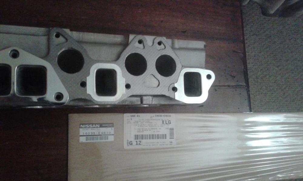
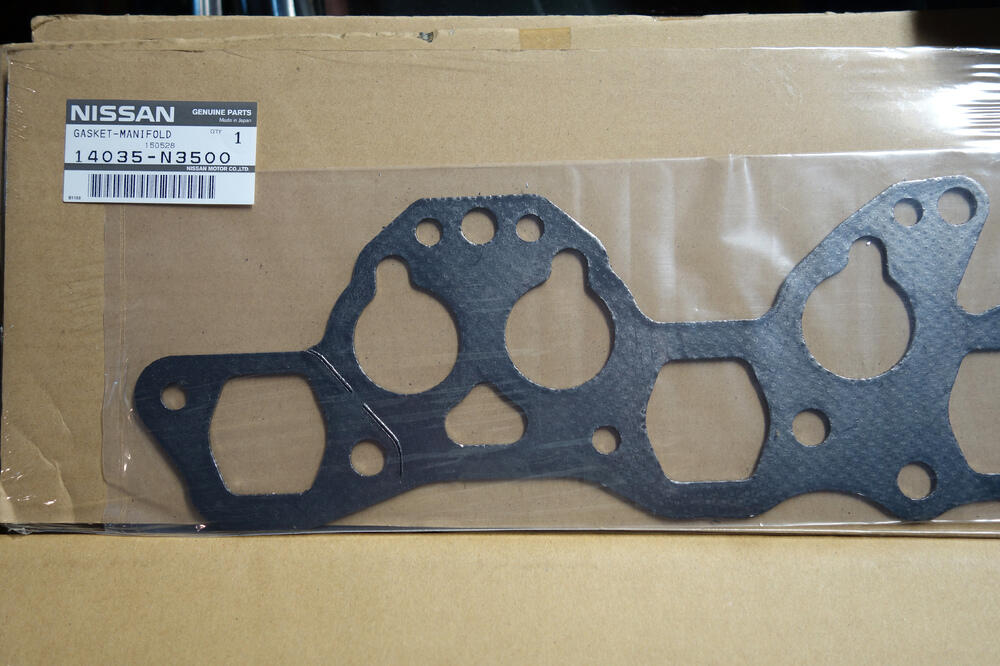
Look between 1st and 2nd spark plugs to see what head you have. Should be an E88 or N42, maybe N47? That will tell us what exhaust port shape you have and whether or not you have the injector notches. If it's an E88 you can use the 240 gasket. Fel-Pro has a universal diamond shape exhaust manifold gasket but it has the injector notches too. From what I remember it will work with carbs but I've never used one so maybe someone can tell us? If it's the OE E88 I would use the right gasket with round intake holes and square exhaust ports. I bought mine through Nissan dealership but zcardepot.com has them too.
-
 Well done! Congratulations from another OO.🎉
 -
 Hi: We are working on a family '74 260Z project, and finally about to pull the L28 engine with the cracked block out of the car and replace it with another L28. The donor engine had fuel injection, but we are going to replace it with the dual-SU carb setup from the old engine. Someone told me a while back to use a specific set of manifold gaskets in this swap, and I feel like they said it was from an earlier engine, but I have now lost that piece of advice and just wanting to hear from some of you folks who know better than me before I order anything. Check this short video? Thanks in advance! Michael Project Z ICT
 -
 Greese joined the community
 -
 Congrats and keep going! All the best to you and your "Z"
 -
 Put on your party hats and toot your horns. Join me in celebrating the 54th Anniversary of the day I bought my 1971 240Z. Today, it sits in my driveway proudly showing its age. Unfortunately, I'm also showing my age and have a little more trouble getting in and out of it and working the pedals than I did in 1971. Great car, great fun, 54 years of great road adventures!
 -
Thanks Captain! This is more the info I was looking for. I guess I will be able to verify once my assortment of plugs arrive from Mcmaster.