.JPG.cfcada9cf1c1b502df3f5f2f2ca3ff36.JPG)

SteveJ
Community Member
-
Joined
-
Last visited
Everything posted by SteveJ
-
If the spark plugs were not torqued to spec, that could give you that result. If the same plugs have been taken out and put back many times, the sealing washers could be compromised. However, there could be some contributing factors, like failing oil rings. In addition to what @jonbillsuggested, do a compression test per the directions in the factory service manual.
-
Should we trust ZCD? There are a lot of variables we don't know about that could have contributed to the failure the insulation of the fusible link. For instance, I believe I saw paint around the connector. Paint, corrosion, etc, would adversely affect current flow, building heat. We don't know the condition of the battery. If it wasn't fully charged, the alternator would be pushing more current across the link.
-
I think this one was better...
-
That is NOT a starter wire. That is a fusible link. Don't know what a fusible link is? Click here: https://media.digikey.com/pdf/Data Sheets/Littelfuse PDFs/Fusible_Link_FAQ.pdf Replace it. It is done. You can get a replacement from Banzai Motorworks (http://www.zzxdatsun.com/catWiring.php WH-03 @zspert) or Motorsport Auto (https://www.thezstore.com/page/TZS/PROD/12-4332). Ironically, the wire should have burned up leaving the insulation intact. In the meantime, disconnect the battery so you don't short out the link. As for the alternator, since it does not have any identifying marks for the L and S wires, I will expand upon my previous suggestions (You need to do at least one.): Buy the Haynes manual for the Frontier (98-04). The electrical section may have the information on what you need. You can get a used copy off Amazon for about $14. How much is your car worth to you? Go to forums on the Nissan Frontier and see if someone with electrical knowledge can answer your question about which is L and which is S. Use a multimeter on the resistance setting. If it has multiple resistance settings, you may have to repeat the steps below on 1M ohm and 1K ohm settings. Touch the common probe to the red wire. Touch the other probe to the B terminal. Record the reading. Touch the common probe to the B terminal. Touch the other probe to the red wire. Record the reading. Touch the common probe to the green wire. Touch the other probe to the B terminal. Record the reading. Touch the common probe to the B terminal. Touch the other probe to the green wire. Record the reading. Repeat steps 1-4 replacing the B terminal with the E terminal (grounding point). Report your readings from each step. If it's like the ZX alternator, I should be able to tell which is L and which is S. I'll explain what I'm looking for when I see the results.
-
Are you trying to figure out how to protect your Z? Locked garage Armed security Live in a gated community with security Always park so the drive wheels are inaccessible Pull the rotor out of the distributor cap and put it in your pocket
-
I can't take credit for the video, but I agree that it's great.
-
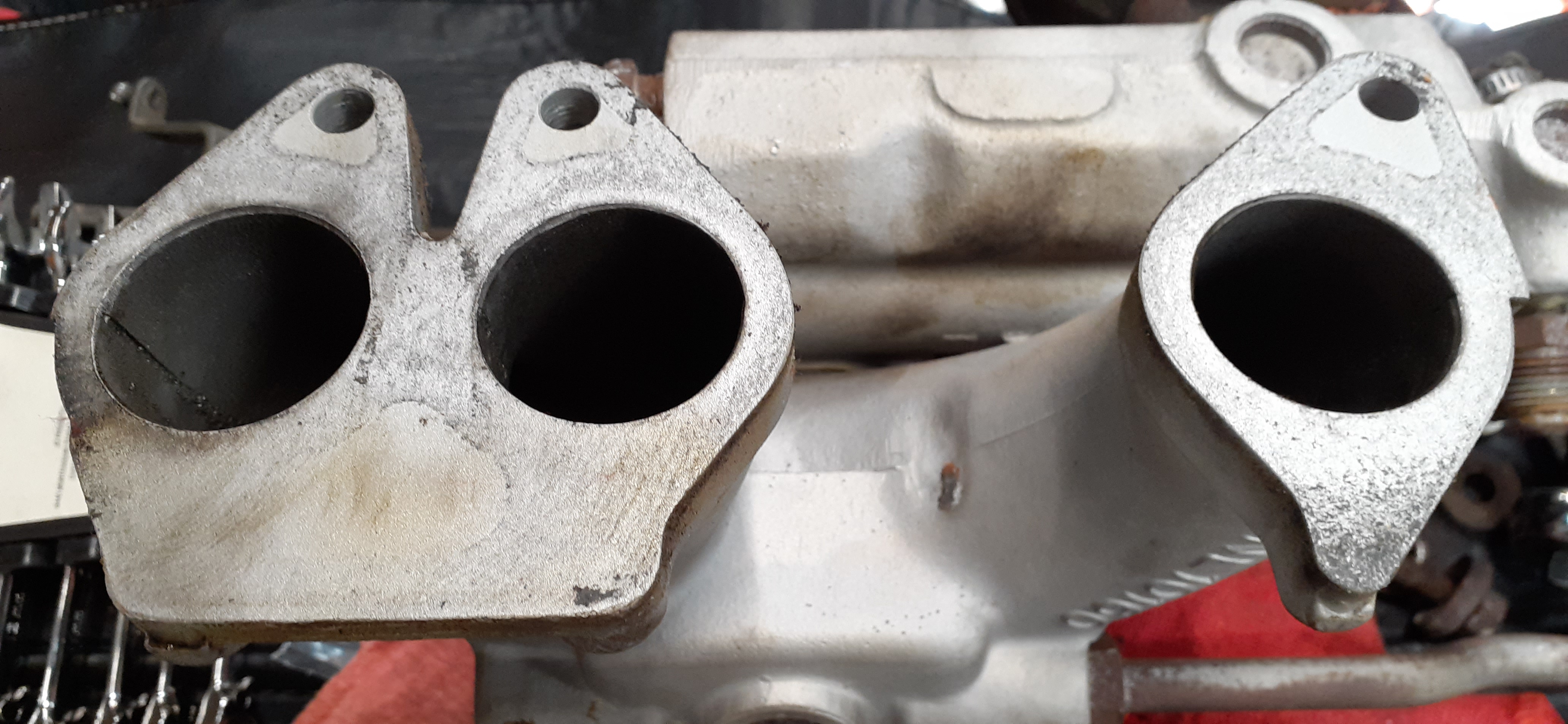
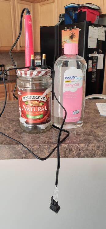
I used this video as the basis for my design. I modified the design to use valve stems for the air inlet and outlet. I removed the valve out of the outlet valve stem. I also used a towel as the wick and soaked the towel with baby oil. I used 1/4 ID vinyl tubing from the outlet stem to the engine with the plan being to use a compression tester hose in the spark plug hole. I forgot that the compression tester hose had a one-way valve pointing the wrong way, though. That meant I needed a small length of 1/2 OD tubing to go over the 1/4 ID tubing. That provided a seal around the spark plug hole that was adequate for the task. With the cam holding open the #2 exhaust valve, I used the soldering iron to heat up the towel. The wife was good enough to operate the tire inflator to supply the air to push the smoke into the cylinder. It didn't take long to see the smoke pouring out of the holes in the air injector.
-
Is there a different way of describing the use of a smoke machine to find exhaust leaks?
-
So, I thought I try some experimenting in the garage today. The wife agreed to join in, too. We generated some heat, and thanks to the baby oil, I found both holes. I felt very satisfied. Now I need to fill the holes. I'm man enough to do it. If I can't remove the old fittings, I'll probably use my cheap wire welder to fill in the air injector.
-
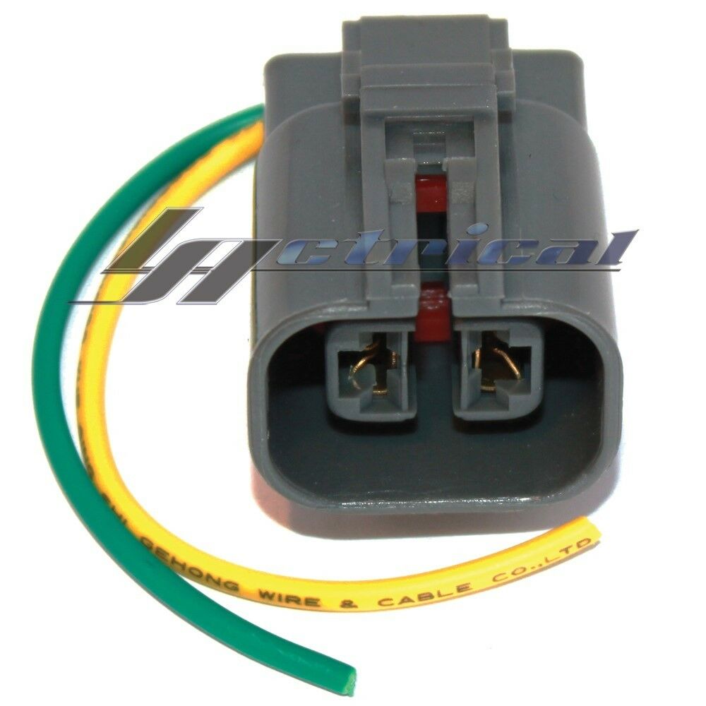
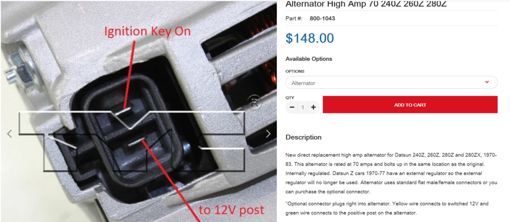
Correct. Color is relative. Position is everything. The picture I included does not show where the green and yellow wires land on the back of the connector. I was trying to show the origin of the description from ZCD. You need to verify which wire is which on the alternator you have. In your photos, it looks like the red wire is jumpered over to the B wire. I cannot tell you with any certainty that your wiring for that is correct as I have not physically examined the alternator, nor have I been able to track down a wiring diagram. Hence my suggestion for you to buy the Haynes manual to try to track it down. Are either pin marked with an L?
-
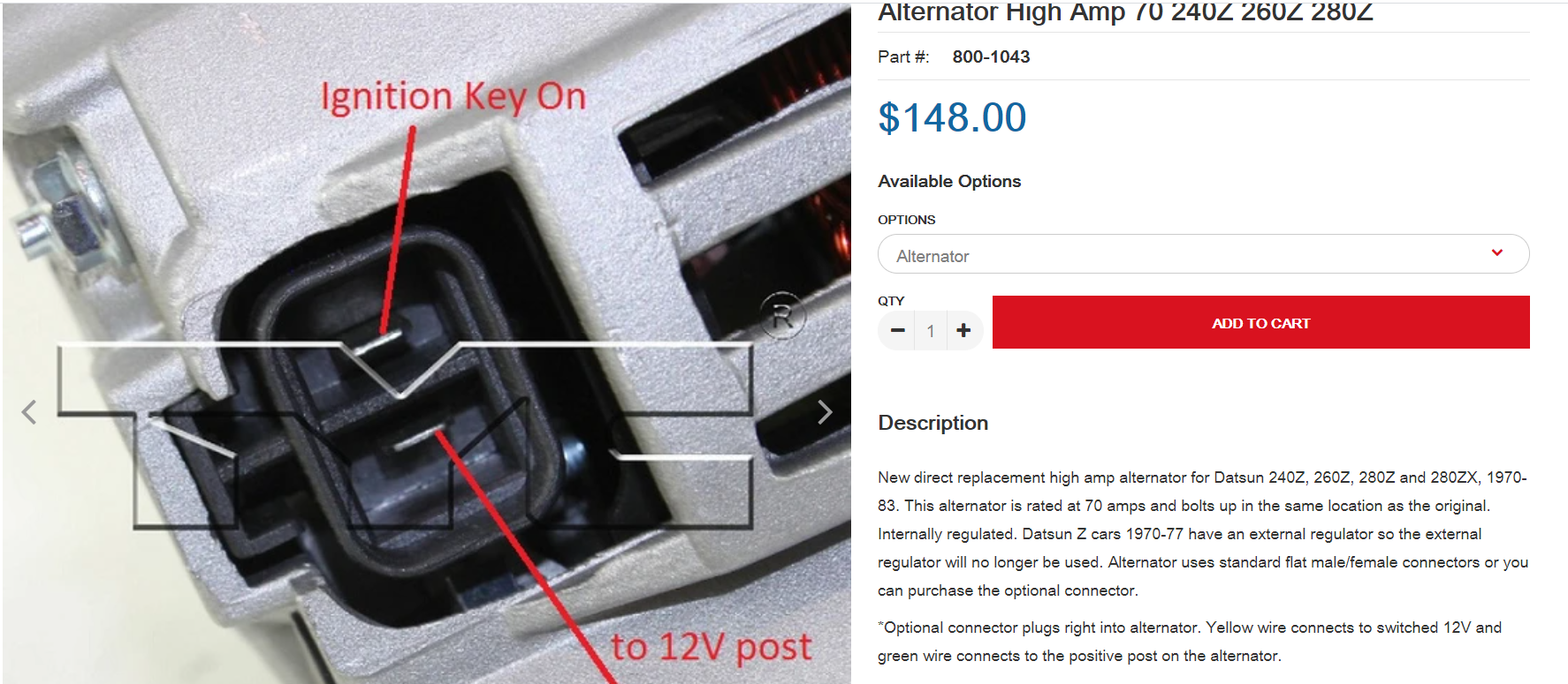
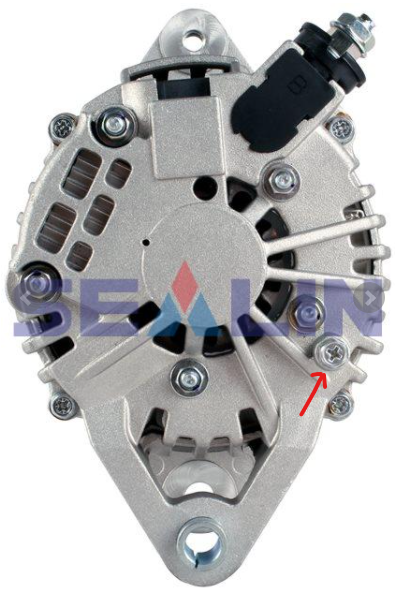
If I understand your question, I answered it in post #7. I did some digging. The alternator in your photos is probably this one: https://www.obbstartersandalternators.com/13778n-lr170-757b-lr170-757br-lr170-765-lr170-766-p-894.html. I saw the 13778N sticker in your photos. I looked up alternator wiring for the Frontier and found this: https://www.ebay.com/itm/302008182071. Picture below. That has the color wires described on the ZCarDepot site. From looking at some other images online, I would think that the Earth terminal is where I have the arrow drawn in the picture below. Can you post photos of the wire damage? Also before testing, verify which wire in the two wire connector goes where. If you can't see any markings on the alternator itself, you may have to resort to purchasing a Haynes manual for the Frontier to get the wiring info: https://www.amazon.com/Nissan-Frontier-Pickup-Pathfinder-Manuals/dp/1563926105/ref=sr_1_3?dchild=1&keywords=nissan+frontier+haynes&qid=1632625664&sr=8-3

-
I took the 260Z to one of the regular car meets I frequent. A fellow GZC member was there, so we parked together.
-
For the diode, you can find a description here: http://www.zhome.com/ZCMnL/tech/280Alt.html For the jumpers at the VR connection, you can get the 6.3 mm 6-pin non-latching connector from Vintage Connections. You can use that connector for the diode. Unplug your VR. Set a multimeter on continuity. Look for the black/white wires from the engine bay harness going to the connector. Test each for continuity with the vertical pin on the T connector at the alternator. The diode would point to the T connector. You can also check with Motorsport Auto to see if they have this in stock: https://www.thezstore.com/page/TZS/PROD/classic12h04/12-4067 It already has the diode.
-
It's what I suspected. I don't think the people at ZCarDepot are not being intentionally deceptive. They understate the changed necessary to integrate the GM alternator into the Z wiring. It would be nice if they just mounted the proper T connector to the alternator AND advise buyers about the need to jumper out the VR for the 70-77.
-
Have you jumpered out the external VR? For the switched wired, you may want to get a 6.3mm 2 pin connector from http://vintageconnections.com/Products/Connectors On the wiring harness T connector, the vertical part of the T is the switched wire. As @Zed Head said, you will probably need a diode on the switched wire, otherwise, you may backfeed the ignition circuit. The arrow (line) on the diode points toward the alternator. The diode can go between the green wire and the connector, or it can be integrated into the jumper for remove the external VR from the circuit.
-
This is why I asked @RJK to post photos. What @Zed Headposted is 100% correct for a 280ZX alternator. HOWEVER, I believe @RJK could conflating the 280ZX alternator with another 70 Amp alternator sold by ZCarDepot. This is the other alternator that is explicitly listed at ZCarDepot.
-
Um, that would not be caused by an MSD ignition. That would be caused by some combination of old battery, bad alternator, and bad voltage regulator. Post pictures of what you're talking about with regard to the new alternator.
-
There was never a wire from the VR to the fuel pump. The yellow wire from between the alternator and the VR is the neutral from the alternator. It had enough voltage and current to energize the coil for the fuel pump relay. If the relay is gone, there is no circuit to control. You have two open circuits.
-
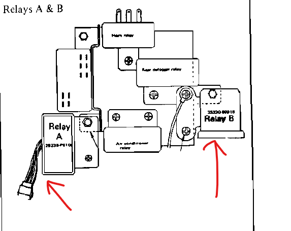
It's been a long time since I removed the piggy back harness for the fuel pump relay. I'm not sure whether or not I trashed it. Anyway, I believe the piggyback harness is between the voltage regulator and the engine bay harness. You should be able to identify a yellow wire that should branch off the harness to the passenger compartment. It goes to the fuel pump relay in the kick panel. The easiest way to defeat the factory modification is just to unplug the relays in the passenger kick panel. Are you looking at connecting the new fuel pump power wire to the old factory wire running back to the fuel pump?
-
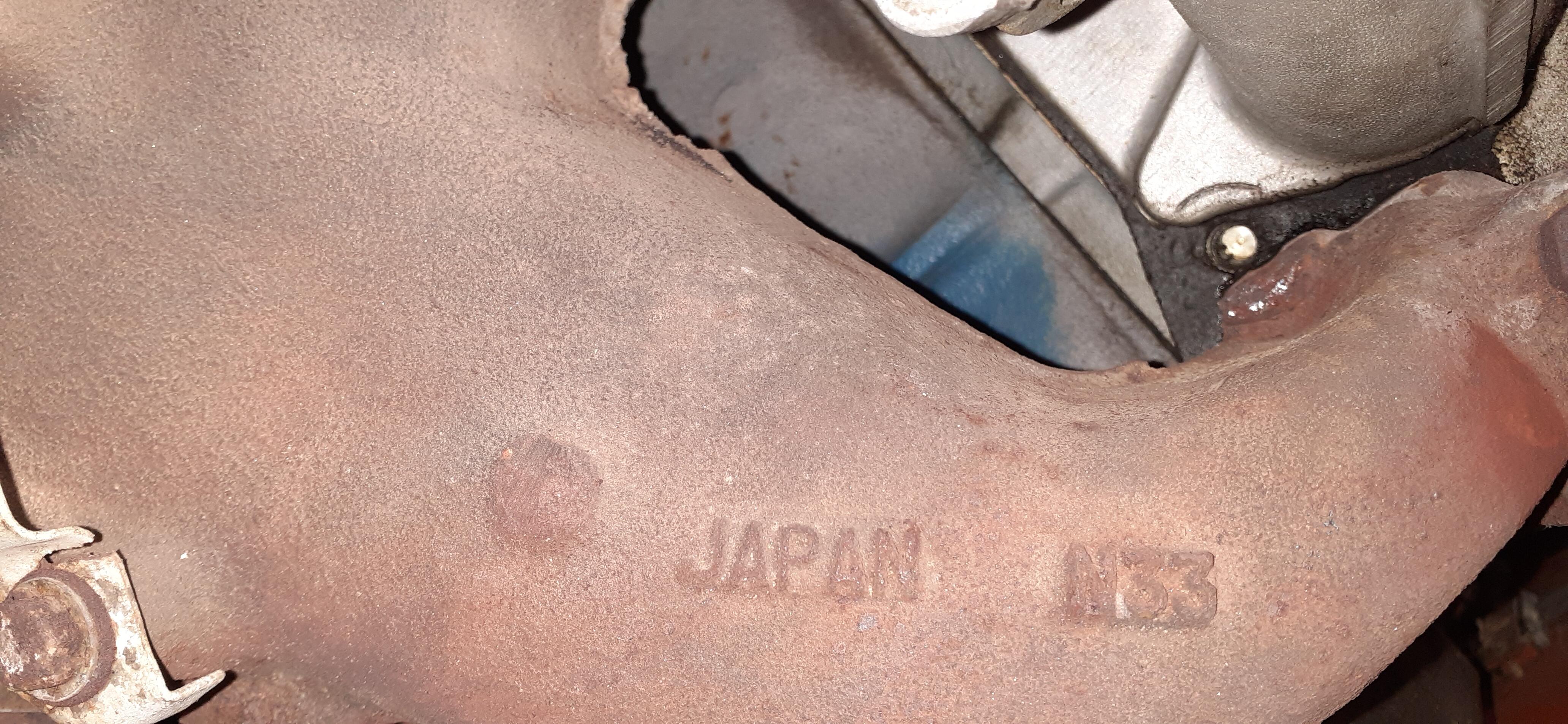
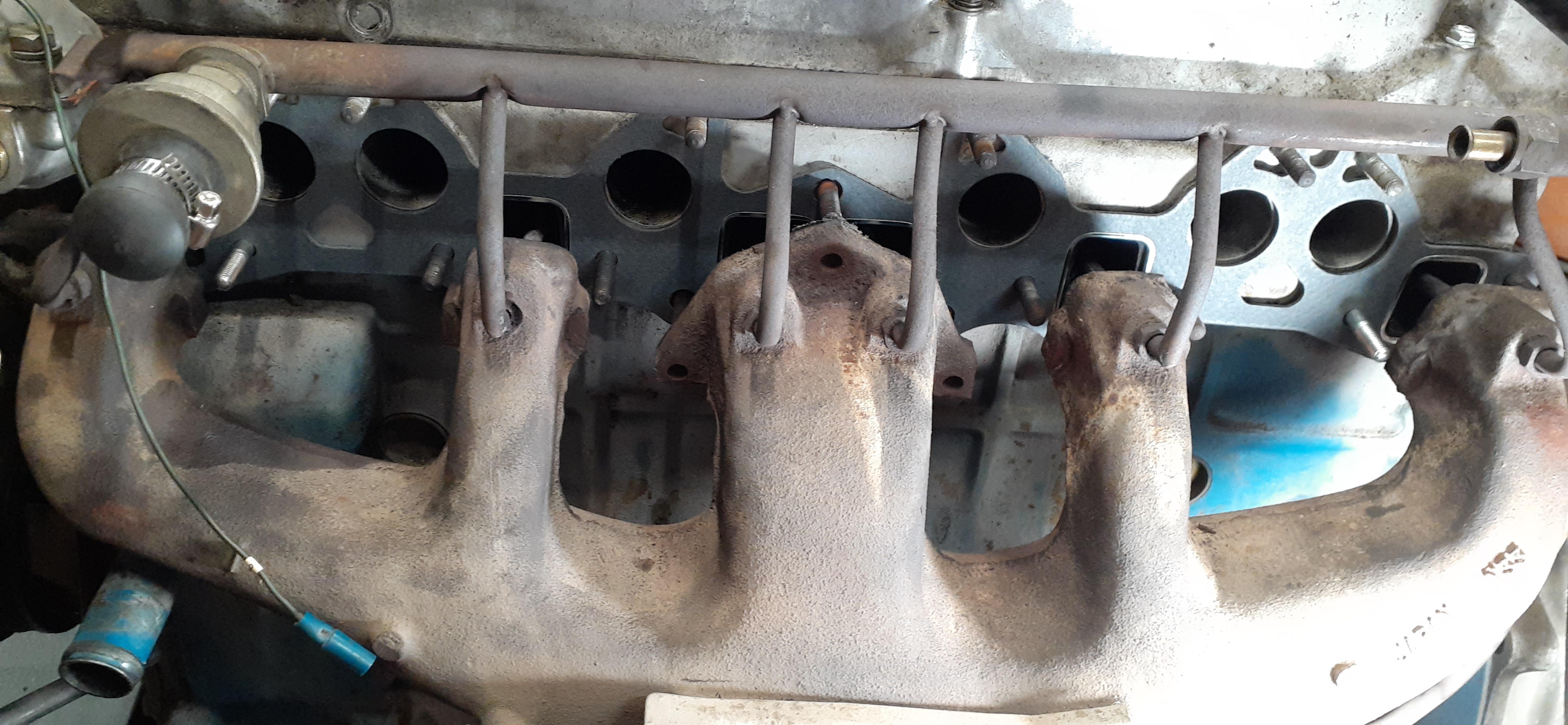
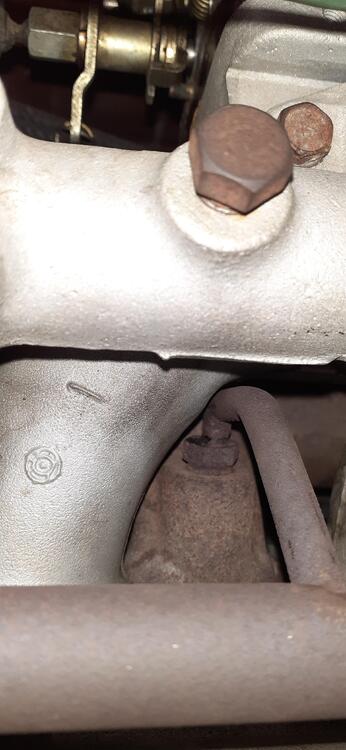
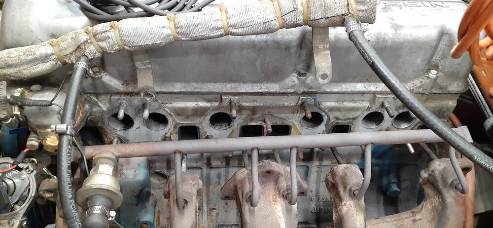
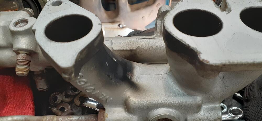
I finally decided to replace the gasket for the intake & exhaust manifold today. I also found some clues as to why my previous effort to tighten the intake didn't work. Among other things, I got a really good view of where about 17 years ago I found that a stud was missing near the #6 exhaust. I just didn't have the skills back then to take things apart and put in a new stud. I also found the nut was missing under the #5/#6 intake runners. More on that later. I also had one stud around the exhaust come out with the nut attached. Fortunately, I had spare studs already on hand. After working everything loose, I removed most of the old gasket. I had to scrape off only a little remaining material. I thought it was clean enough for the new gasket. I worked the new gasket into place relatively easily. Before putting the intake back in place, I took a quick look at it. There was definitely an exhaust leak at #2. Also, there were signs of a leak below the #5/#6 intake runners. I did wipe it down a little. You can see the smears below the intake. Anyway, I got the intake and exhaust cinched down nicely, and the carburetors are back in place. Tomorrow, I will re-balance the carburetors since I hope I have rid myself of all of the leaks around the intake and exhaust.


-
It helps to share some of the surprises, especially when people join here because they want to "wake up" an old Z. On the other hand, I haven't been documenting some things like the oil leaks from dried up seals...
-
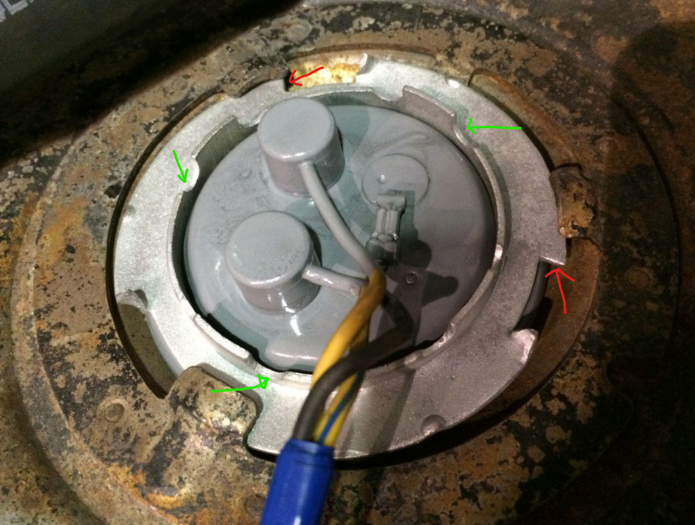
On my 240Z and 260Z, I used about any tool I could fit to press on the flat areas at the red arrows. You can't push too hard there, as you may warp the ring. The early cars didn't have the inner ring area where I have the green arrows. I would think after removing the sending unit wires and low fuel level wire that you may be able to get a set of pliers that open wide enough to go across that area. Hat tip to @siteunseen for the picture I lifted from this thread:
-
Yes, imagine the clip below the hole. It holds onto the arm going through the hole. Maybe I can use one of my spare mechanisms for show and tell.
-
I'd just have to remember where I stashed my diodes...
-
I can make them, too.