.JPG.cfcada9cf1c1b502df3f5f2f2ca3ff36.JPG)

SteveJ
Community Member
-
Joined
-
Last visited
Everything posted by SteveJ
-
What are you testing for? Are you looking for short circuits, or are you trying to find out how big of a fuse you can put in the circuit before it blows? Have you tried what I suggest in post #16?
-
An interesting aside, I was looking at various wiring diagrams for the Frontier, and I noticed that the wire from the battery is still white and the wire from the ignition in ON is still black/white (shown in a different diagram). Granted a lot of other wires have changed, but they have kept some of the basics the same for a long time. Note that there is a black rectangle by the S & L on the alternator in the drawing. That shows the orientation of the clip. Rotate that 180 degrees, and it looks like the one in the picture in my previous post.

-
That is correct, provided that ZCarDepot identified the terminals properly. From what I can tell, they did. https://trans-sen.en.made-in-china.com/product/VSGJimnPJKWj/China-Alternator-for-Nissan-Almera-X-Trail-2-2L-Mitsubishi-A3TB0771-.html

-
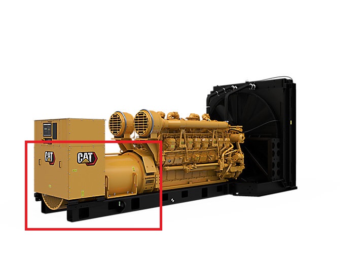
Stop and focus. I'm guessing that you're worried about making another mistake, and that's keeping you from reading carefully. From my previous post, "with the key in OFF, you should have an open line on the L or "lamp" wire on the T plug to the white wire, and it should have continuity when the key is ON. That is because it is a switched source." S - Sensing battery voltage. When the battery voltage drops, the voltage regulator excites the field to raise the output voltage of the alternator. L - Lamp: On a lot of old cars, there is a light to indicate a charging failure. Under normal conditions, the voltage is the same on both sides of the light. When the alternator starts to fail, the voltage drops on the alternator side, and the bulb lights up. When the car is off, the alternator is not producing any power (and therefore no voltage), so if you are not using a switched source, the charging light would be lit all of the time. By the way, these are the alternators I'm used to playing with. The alternator is inside the red rectangle. This one is a 16 cylinder engine with quad turbos. It will put out over 2 megawatts of power. The usual voltage output is 4.16kV to 14.4kV.
-
You know how to use the tool to give you the answer you seek. The S or "sense" terminal is to sense the battery voltage. Therefore, with the MSA jumper plug in place, you should see continuity between the sense wire at the T plug and the white wire where the fusible link plugs in. Just make sure that you Have the black (common) probe at the T plug. Have the ignition key in OFF. Conversely, with the key in OFF, you should have an open line on the L or "lamp" wire on the T plug to the white wire, and it should have continuity when the key is ON. That is because it is a switched source.
-
I looked for the Xenon air dams recently at Jegs. It doesn't look like they carry them anymore, at least for the Z car.
-
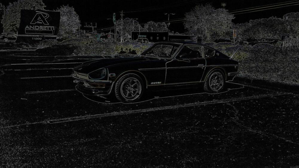
Who here plays with photo software? What are your favorite effects?

-
-
Start by giving us more background on the car. Who put in the new switches and why? Why do you think it has a headlight harness upgrade? The one sold by MSA/Dave Irwin has relays, but @Zs-ondabrain(aka Dave Irwin) had to modify the headlight connectors to make it work. Do you have a test light? Do you feel comfortable taking things apart? Are the parking lights working?
-
Good. That's exactly what my intention was.
-
Well, there was the time I spent about 3 hours trying to figure out why my battery voltage dropped to zero as soon as I turned the key to ON. I was sure there was a short. I just had to disconnect the right thing... Oh, the battery was bad. It had potential, but it didn't have the energy to drive current. As soon as it had a load, there was no more potential. Now, you can think that you wasted your time, or you can realize that you learned something about how to diagnose electrical circuits with an ohmmeter. Okay, it's time for one more door open story. Around 40 years ago, my brother was installing a new stereo into the family's 68 Mustang. He needed to find a wire that went to ground. Searching around, he found one. He finished the install, and the stereo was cranking out the tunes. So after putting tools away, he got in the car and was going to drive around and enjoy blasting the music, only the stereo wasn't working anymore. So he stopped, got his tools out, but the stereo worked fine again. Shortly he realized that the ground wire he selected happened to be downstream of the dome light. When the door was open, the switch was closed, and the stereo worked. With the doors closed, the stereo lost its ground. He found another ground wire for the stereo.
-
It doesn't hurt to make sure RJK knows that he's probably reading light bulbs. Actually, one time I was trying to find a battery drain on a 280Z. I started at the fusible links and moved down to the fuse box. I only found one fuse with current flowing through it. I realized that it was the dome light circuit, and the doors were opened. D'oh! I closed the doors and measured again, only to find the circuit still had current flowing. The door switch on the passenger side was not opening when the door was closed. I gave the owner the option of pulling the fuse or paying me to remove the switch. He pulled the fuse.
-
Yes, but if I'm not mistaken, that fuse was pulled in the photo in post #28. The bottom line is that the readings may indicate a battery drain, but so far, I don't recall seeing a reading that would indicate a dead short.
-
I think you are muddying the waters this time, Capt. RJK had the insulation burn off his fusible link without the link blowing (assuming that it was fusible link wire used) after installing the Nissan Frontier alternator. Now he is trying to verify whether or not he has a short somewhere. Since he doesn't seem to have a car battery available, he is using an ohmmeter. I have been giving advice on isolating circuits to verify there isn't a shorted branch that could have taken out the fusible link. In that case the I=V/R equation is very relevant because I'm trying to get him to focus on low resistance readings. The reading he got at the fusebox is probably a light. If not the parking lights, maybe the engine bay inspection light. It's on the same fuse. After confirming there isn't a dead short in the cabin, I asked him to connect the engine bay connections one at a time and measure. I'm thinking that the likely culprit was miswiring on the alternator with likely no other damage on the wiring.
-
I imagine that if @RJKisn't following my directions VERY carefully, he will be measuring the impedance of the loads on several branches. That is what I'm seeing with the readings so far. So, to RJK, as you take your readings, keep this in mind: I=V/R. In other words, current is voltage divided by resistance. We can also put the equation as R=V/I. This is how to think of it. You have about 12.6 volts as a lower threshold for a good battery. You want 40 amps or less flowing through the fusible link, and the 40A value is only if the battery is down on charge. (By the way, use a battery charger to help a weak battery, not your alternator.) so the resistance readings on the main wires (white or white/red) that would be giving you problems would be 12.6/40 or about 0.32 Ohms (or less). You seem to be getting higher values than that. It could mean that you have disconnected the short, or you burned off the short (not a good thing). I've been giving you guidance to verify that there is not a high impedance connection to ground (the remaining connection after you burned off a short) that cannot be accounted for by typical loads such as parking lights, headlights, dome light, inspection light, etc.
-
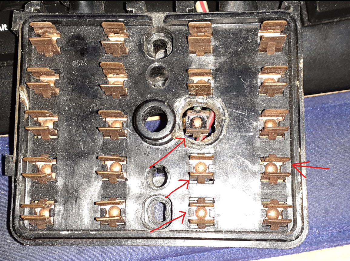
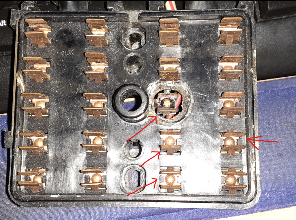
With the measurement at the fuse box, you need to do things a little differently. While you took out the 4th fuse down, you are measuring on the common feed for fuses 3, 4, and 5. You need to pull all three fuses (circuit isolation). Also make sure the headlight switch is in the OFF position. Also you may want to unplug the inspection lamp under the hood. Also test the fuse box with your doors closed. As @Captain Obvioussaid, you want to make sure you don't have a switch on, and that includes the switches for the dome light. With the fuses pulled (and the switches off and inspection light disconnected) take measurements to ground at the points indicated by arrows in the photo. Just for a reference, 2.6 ohms will drain your battery quickly, but it should not burn up your fusible link. That's a little less than 5A draw. That could be a couple of light bulbs you're reading. As I said in a previous post, reconnect things in the engine bay one at a time and re-measure. If you do have a short, I'm more willing to believe its around the alternator. (When I have problems with my own cars, my first thought is, "What did I f*** with last?")
-
https://www.zcar.com/threads/brake-line-size.58963/
-
That's why I made that drawing for the turn signals and included the connectors. It's really fun to diagnose the fan wiring. I keep an old fuse box handy so I can locate the fuses easily when I'm responding to posts.
-
If it's only a couple of gallons, use the drain plug at the bottom. Just make sure you have a good sealing washer to replace the old one. I'm about to drain/replace the tank in my 240Z. It has well over 5 gallons in it, so I have to siphon first. After I get most of it out, then it will be the drain plug.
-
I think you are understanding the testing concept now. Now imagine a 3 inch bundle of wires, all of them are grey. One of those wires was not run correctly, and you have to find out which one it is. That really helps improve diagnostic skills. I find wiring diagrams and wiring harnesses with color codes to be SO much nicer.
-
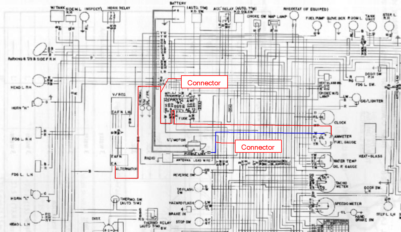
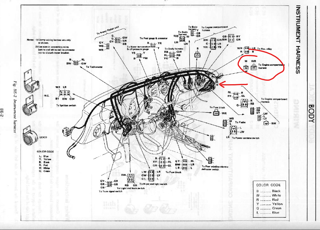
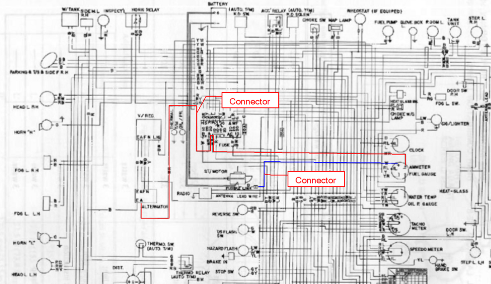
Photos would help to show what was disconnected and where you were measuring. Basically, I'm trying to get you to isolate the circuit. Here is a simplified view using the wiring diagram on page BE-5 The red line represents the white/red wire. The blue line represents the white wire. The wires do not intersect directly. The white wire goes from the fusible link through its connector at the junction of the engine harness and dash harness. From there it has two branches. One goes to the fuse box, and the other goes to the ammeter. The white/red wire goes from the alternator through its connector at the junction of the engine harness and dash harness. From there it goes to the fuse box and comes back out where it branches. One branch goes to the ignition switch, and the other goes to the ammeter. The ammeter is the spot where the white and white/red wires intersect. Again, make sure you have BOTH connectors disconnected. Make sure the white/red wire is disconnected from the alternator. Also make sure the sense wire is disconnected from the alternator. If you are going to find the short, isolation is critical. At that point, test for the white wire to ground and white/red to ground. If you get OL readings on the white/red, start reconnecting one at a time and re-test.
-
Too bad your view was blocked by that sweaty fat guy.
-
R - Right Headlight R/Y - Left Headlight R/L - Inspection Light G/L - Front/Side Marker Lights Of those 4 wires, only the R/L wire doesn't go through a switch. Pull the 4th fuse down on the right side of the fuse block. Reconnect the 4 pin connector and test again.

-
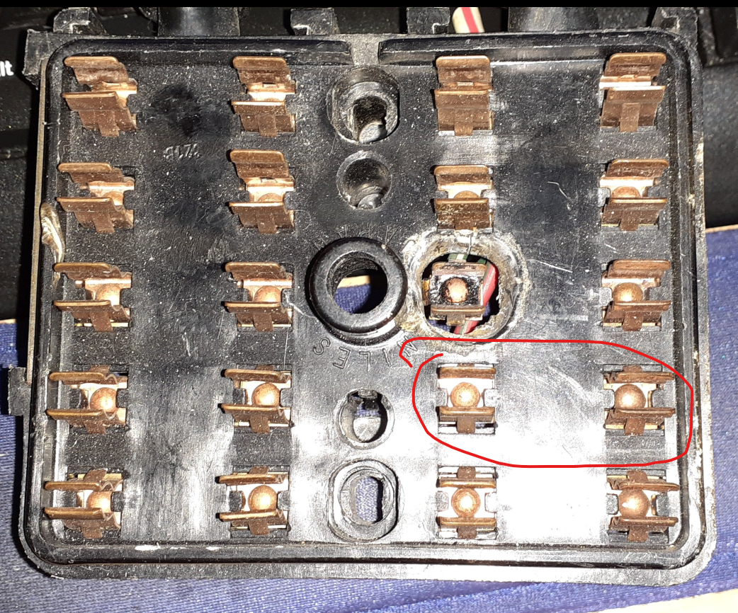
So locate the two connectors circled. They will be around the dash on the passenger side. Disconnect them and repeat the resistance measurements in the engine bay. Disconnecting those wires should isolate the wires from the alternator and battery in the engine harness from the dash harness. Also check resistance from the white/red wire at the alternator to ground.

-
Is the alternator connected or not? If it was connected, try the test with the alternator disconnected. If the readings are still low, post the year of your car so I can tell you what to disconnect at the body/engine harness junction to try to isolate the short better.