.JPG.cfcada9cf1c1b502df3f5f2f2ca3ff36.JPG)

SteveJ
Community Member
-
Joined
-
Last visited
Everything posted by SteveJ
-
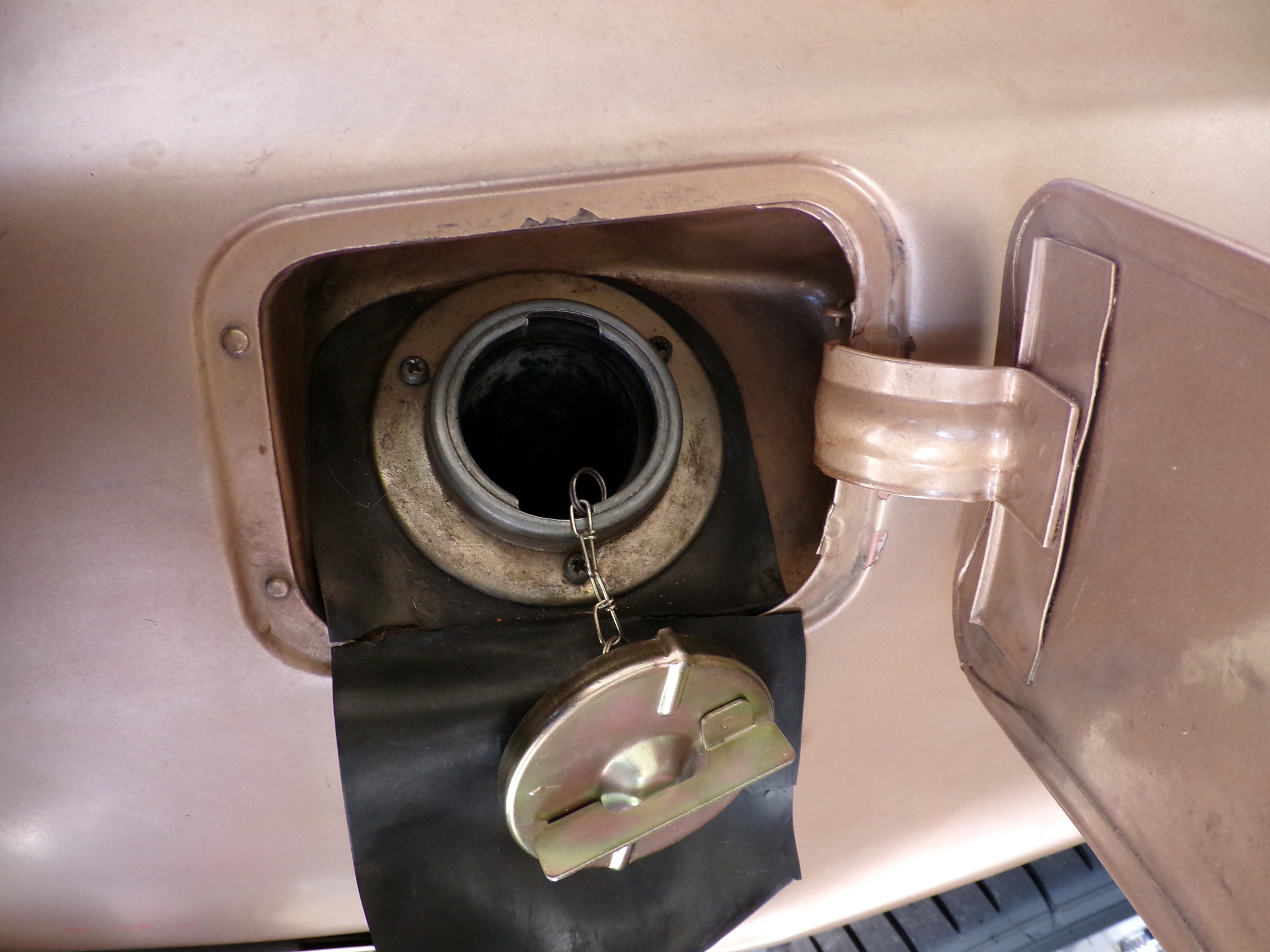
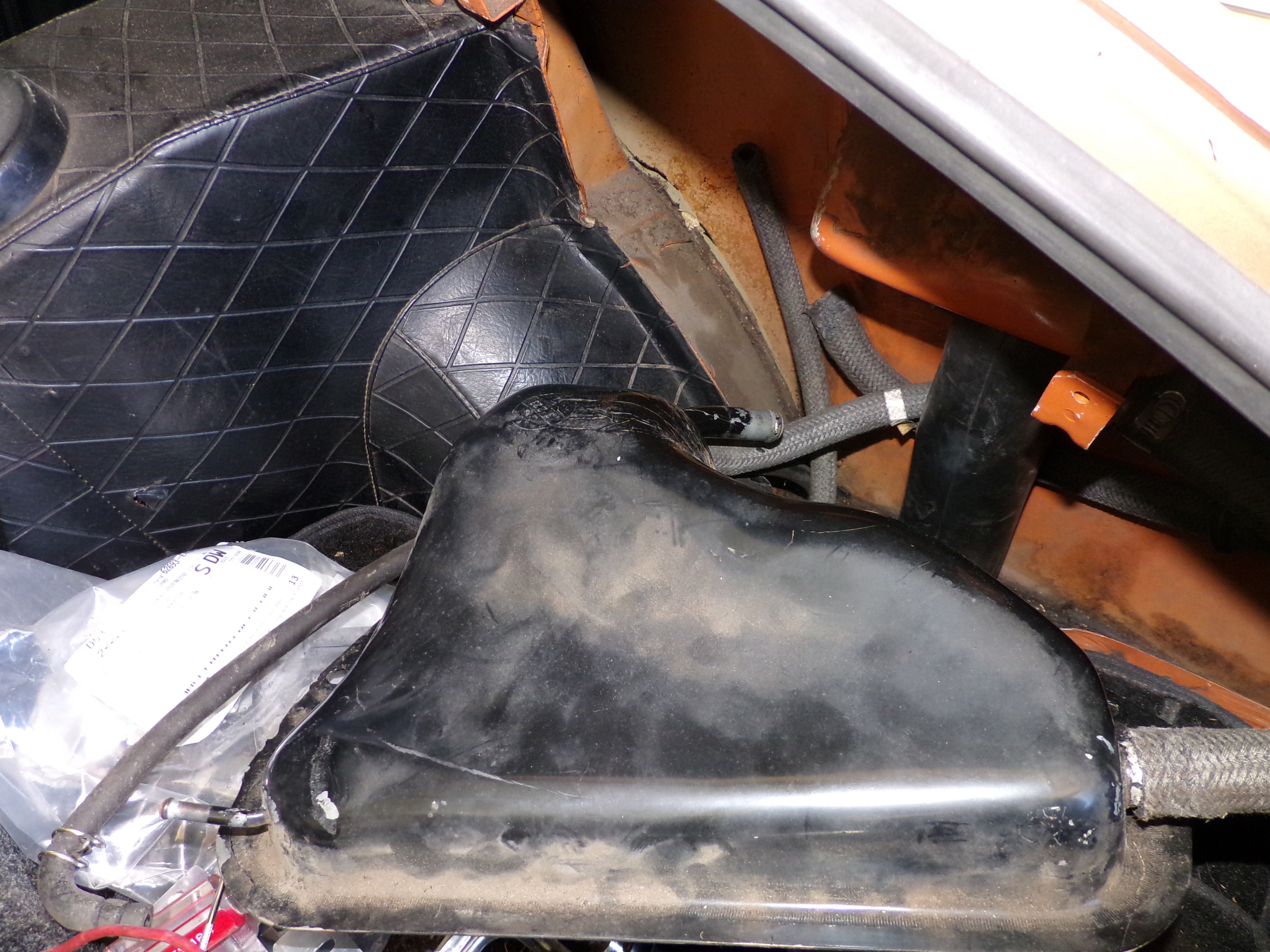
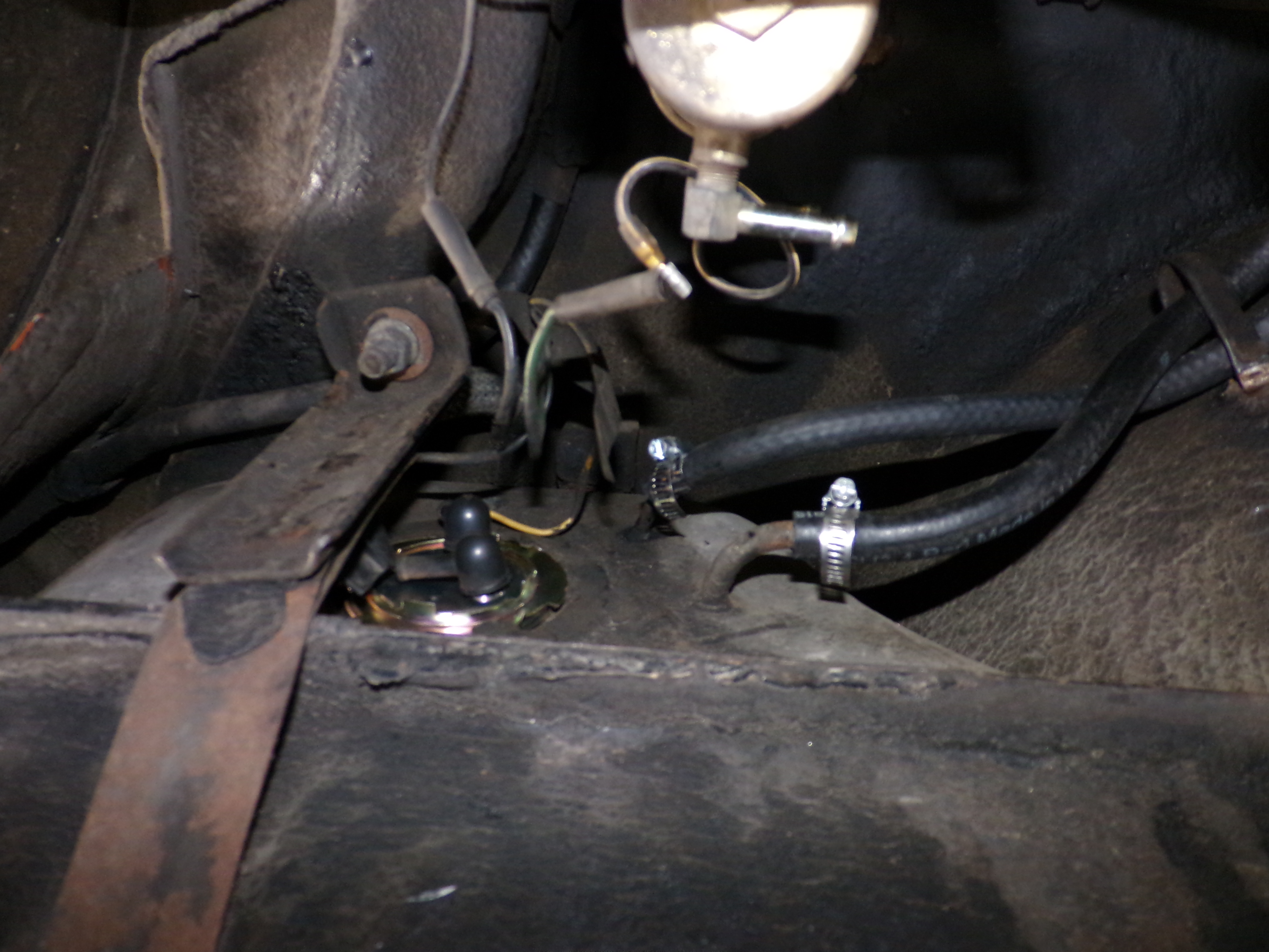
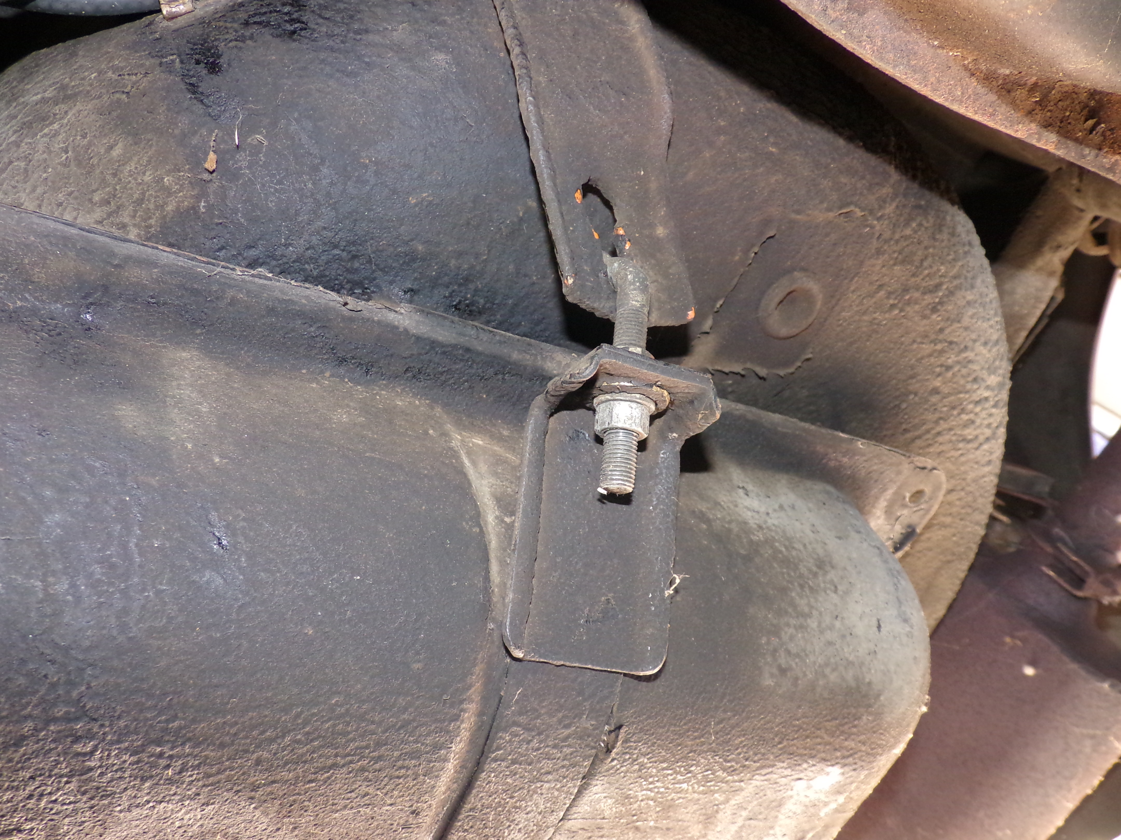
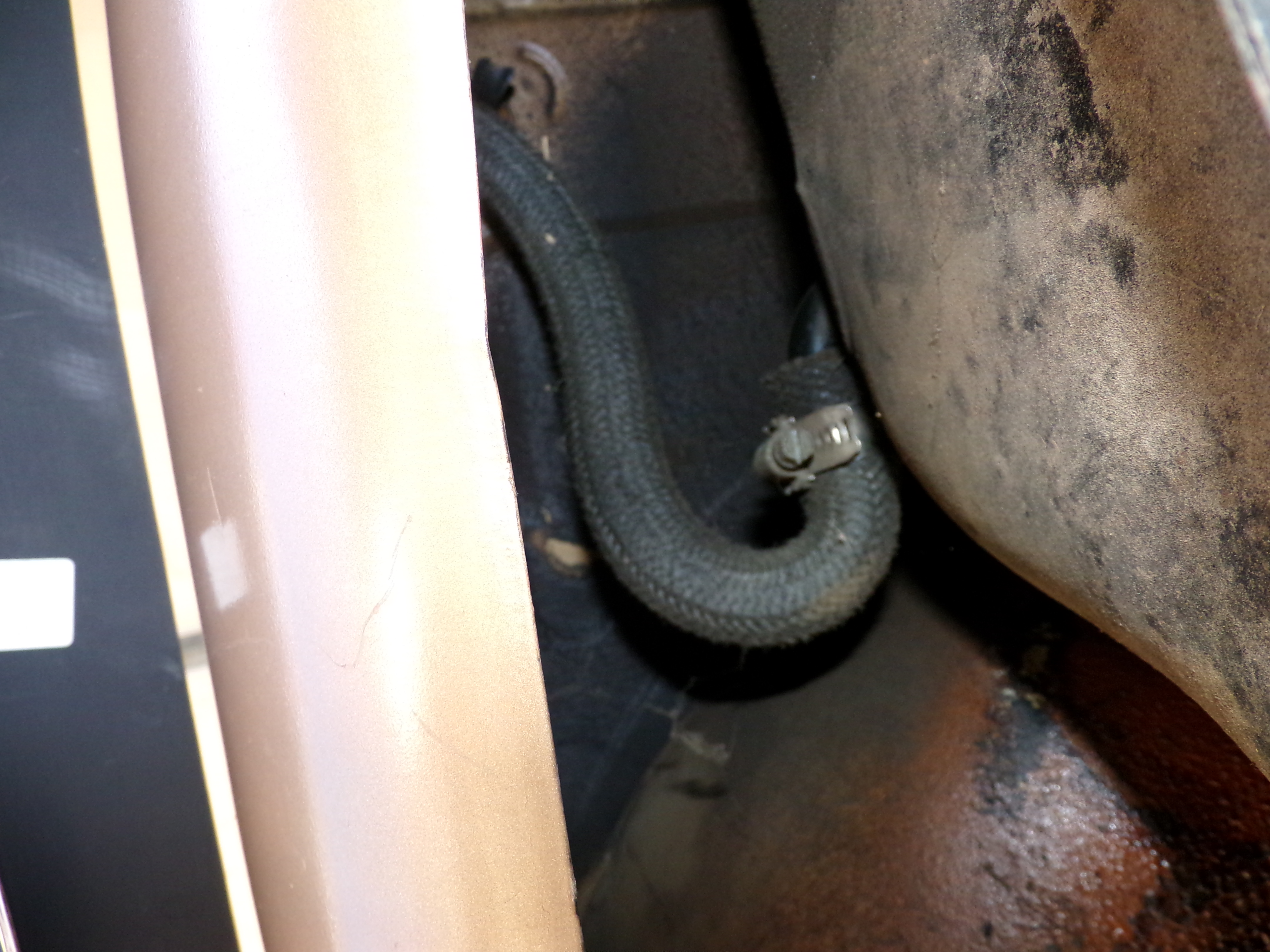
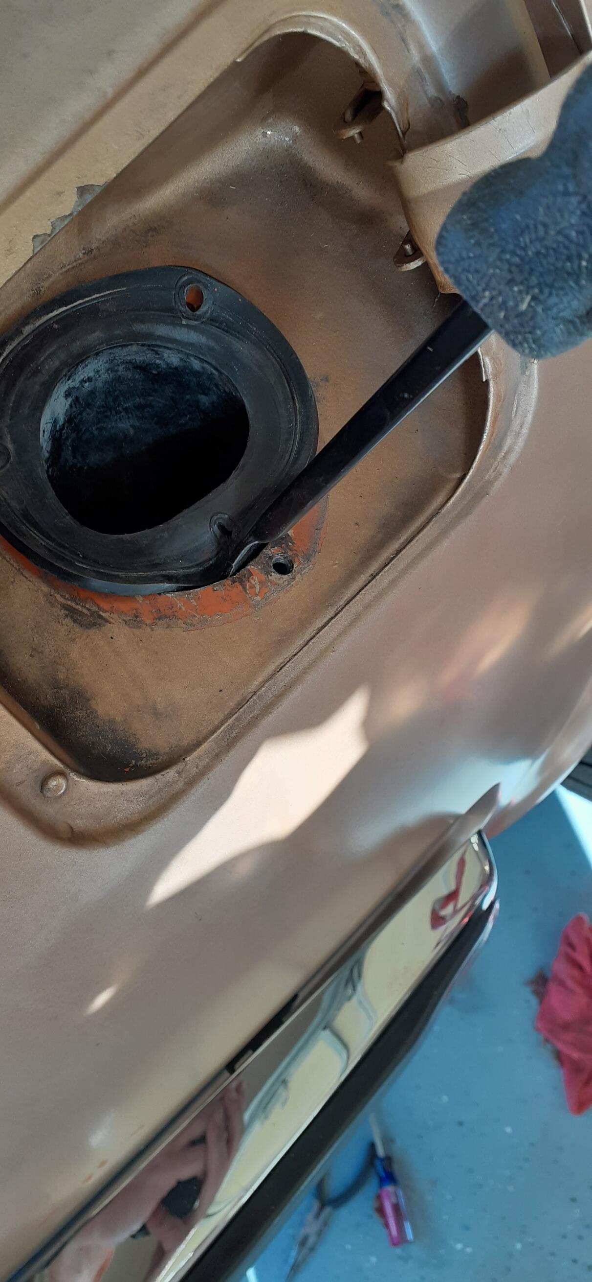
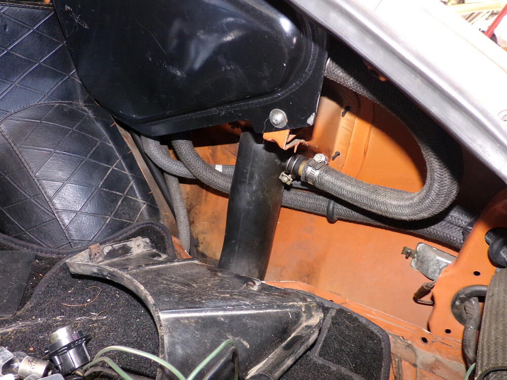
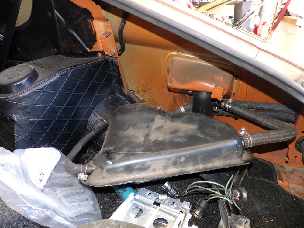
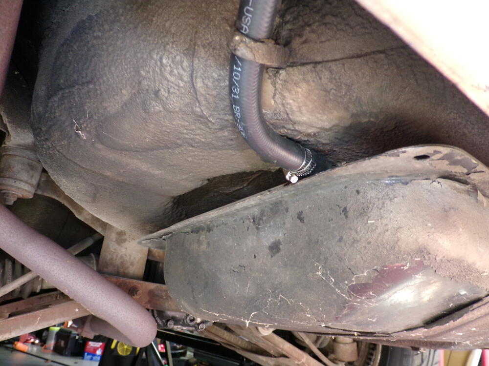
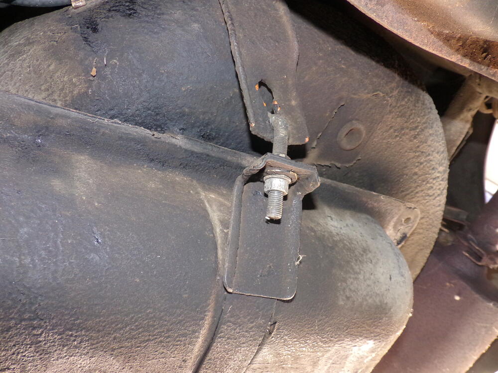
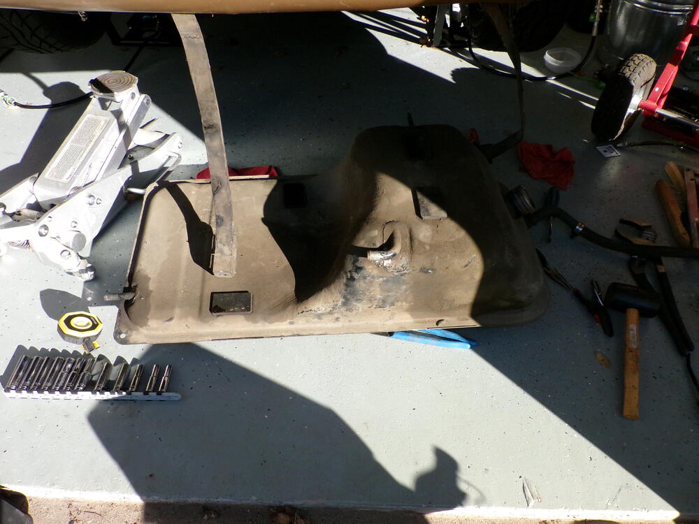
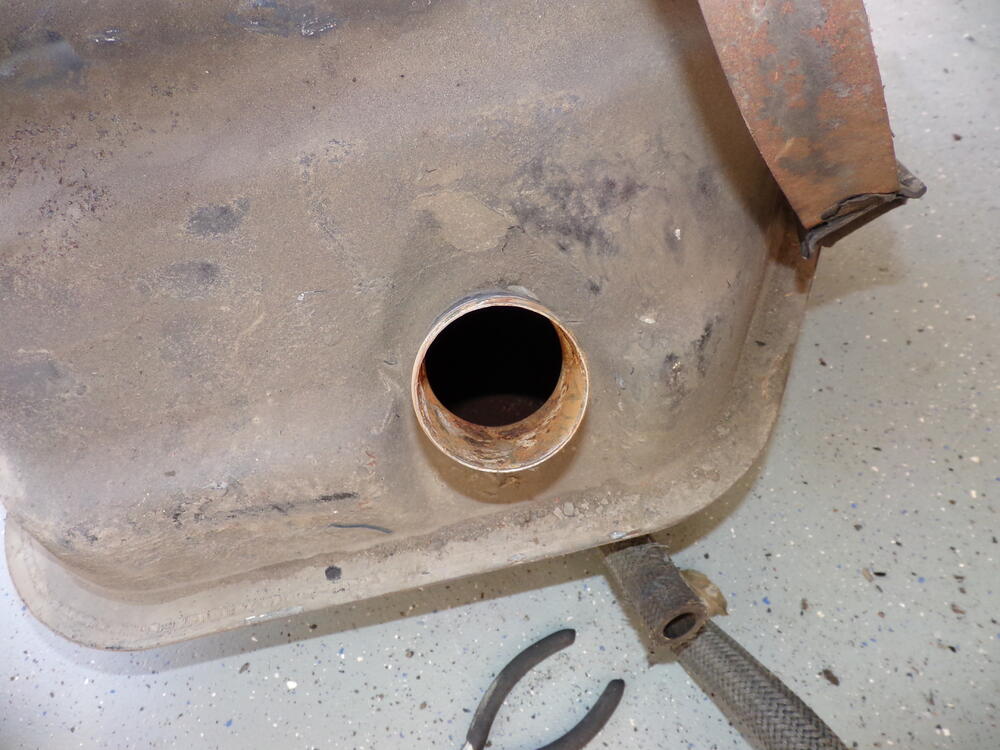
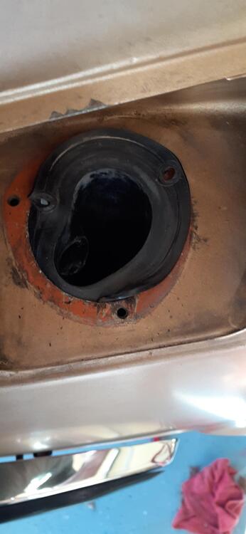
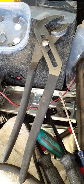
So I finally had some energy and motivation today. That meant I could drop the old tank. In case anybody needs a primer on dropping the tank, this may help. I already had the trim panels removed and the gas tank drained. Next is taking hoses off the expansion tank to give slack underneath. The only hoses that IMHO have to be removed is the large vent hose that goes through the floor on the right side near the tail panel to the tank and the hose from expansion tank to filler neck. Taking off the other hoses just ease access to the large vent hose. It's good to have some small picks to run along the inside of the hose where it is on the neck of the expansion tank to break loose the hose. I replaced all of the vent hoses only 24 years ago, so they are in fairly good shape. Go ahead and remove the 3 screws on the filler neck. There is only one vent hose that is somewhat accessible before starting to drop the tank. It's on the left side of the tank. Even then, you'll need to loosen the nuts on the J-bolts some to get full access to it. Before you take off the J-bolts, on the passenger side, remove the leads to the fuel sender and the supply and return hoses. With the driver side vent hose removed, and the tank straps disconnected from the J-bolts, you should be able to access the small vent hose on top of the tank. It is a good idea to support the left side of the tank with a floor jack or jack stands to keep from stressing the hoses. You'll also want to get the filler neck down to access the hose clamp holding the filler to the tank. That was a challenge for me this time. At first I tried to pry the lip in. That didn't work so great. Then I got out the big honkin' pliers and squeezed the neck enough to get the lip through the top hole. At that point, I fed the large vent hose through the floor to give enough slack for the tank to come down more. I got the large vent hose off the tank. Then I used a small pry bar to push the filler neck hose off of the tank. The tank was on the ground. I don't think it was as bad inside as the one @siteunseenhad with his display of chips that he likes to use, but I don't want to take any chances. The old tank is in the shed for now. I'll probably try to clean it up. The new tank will go in the week of Thanksgiving since I'm taking off from work that week.


-
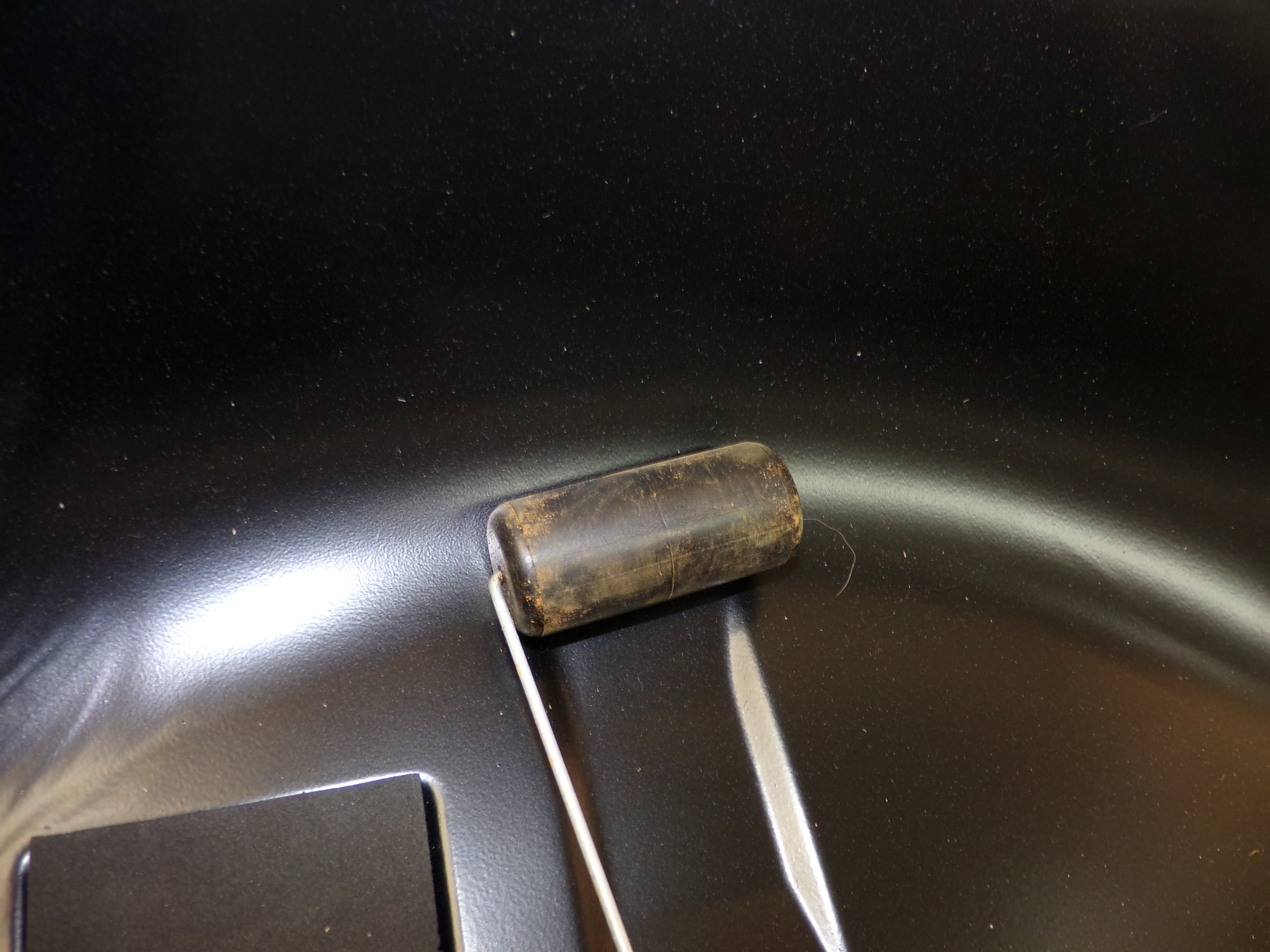
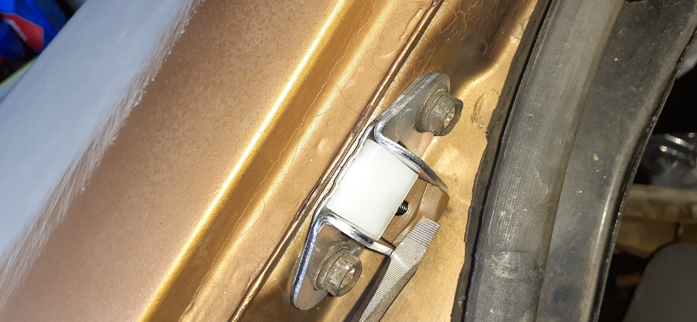
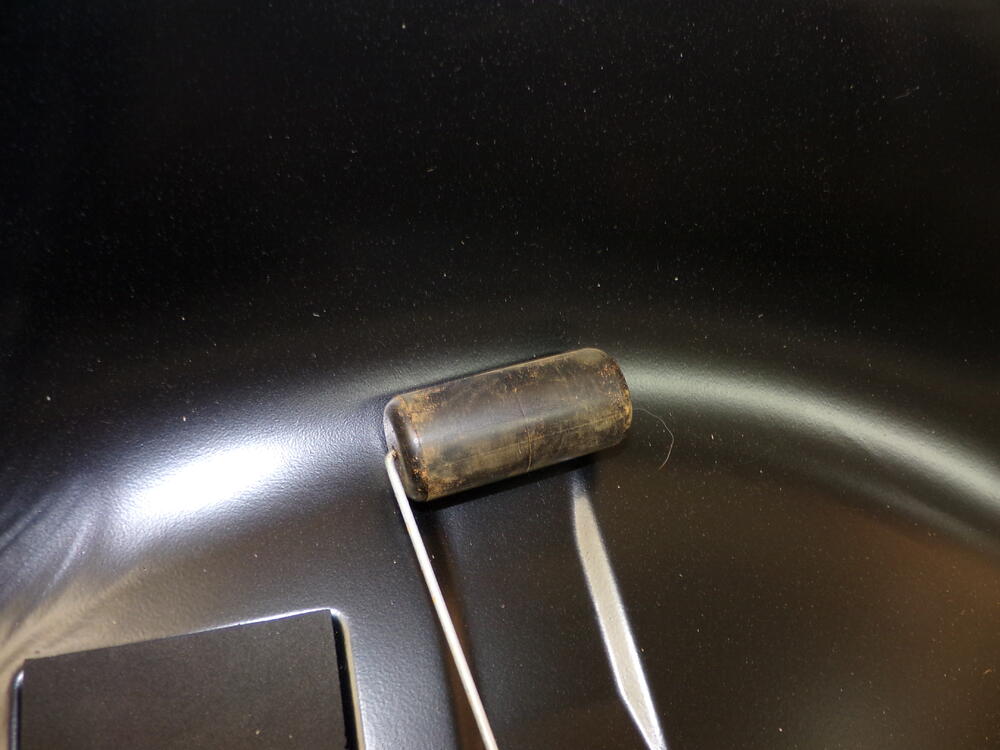
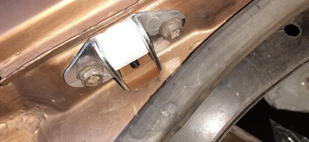
Here are a couple of pictures of a new stopper. The lower rubber piece is about 10 mm tall at the thickest point. I think that ridge is about 3 mm thick. As you can see it is quite pliable. I hope this helps in your thoughts to restore them. Frankly for me, it was too easy to spend a little money and never have to think about it again.

-
Yep. @One Way The lower block that disintegrated is made of rubber on the factory ones. I just put a set on my 240Z recently. It is a relatively soft rubber, too. Maybe I can shoot some photos and video after I'm done wrestling with the gas tank today.
-
Post photos of the front calipers showing the bleed screws.
-
-
-
-
Oh, and I bought one of these 7 years ago, but it doesn't have a tachometer. https://www.amazon.com/gp/product/B000BSWEHS/ It still works, but I have to use a separate tachometer when tuning.
-
Timing lights are hit and miss anymore. The Innova Digital should do what you need for a timing light. https://www.amazon.com/dp/B000EVYGV4
-
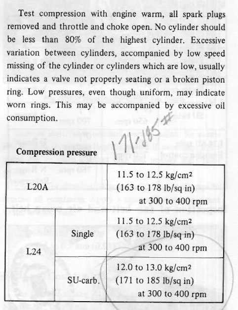
It is possible your readings will go up since the other cylinders won't be pushing as hard against the cylinder under test.
-
From the FSM on compression testing. Of course, you'll have to do it cold right now, but follow the rest. Note that the compression ratio will probably be lower with the engine cold, but there should not be a lot of variation in readings.
-
Use this stuff for starting. It's the cheapest you'll find.
-
Wow, how about shooting some video of you taking measurements just to make sure you're doing it right. Those measurements are way off.
-
Considering the engine was worked on, the readings seem low and all over the place. However, there can be variability in compression gauges. Also, technique is important. Make sure you look at what the ET section of the FSM says.
-
-
Here is a good tutorial on how to do the valve adjustment: https://web.archive.org/web/20080720024048/http://www.picturetrail.com/gallery/view?p=12&uid=786489&gid=1803105
-
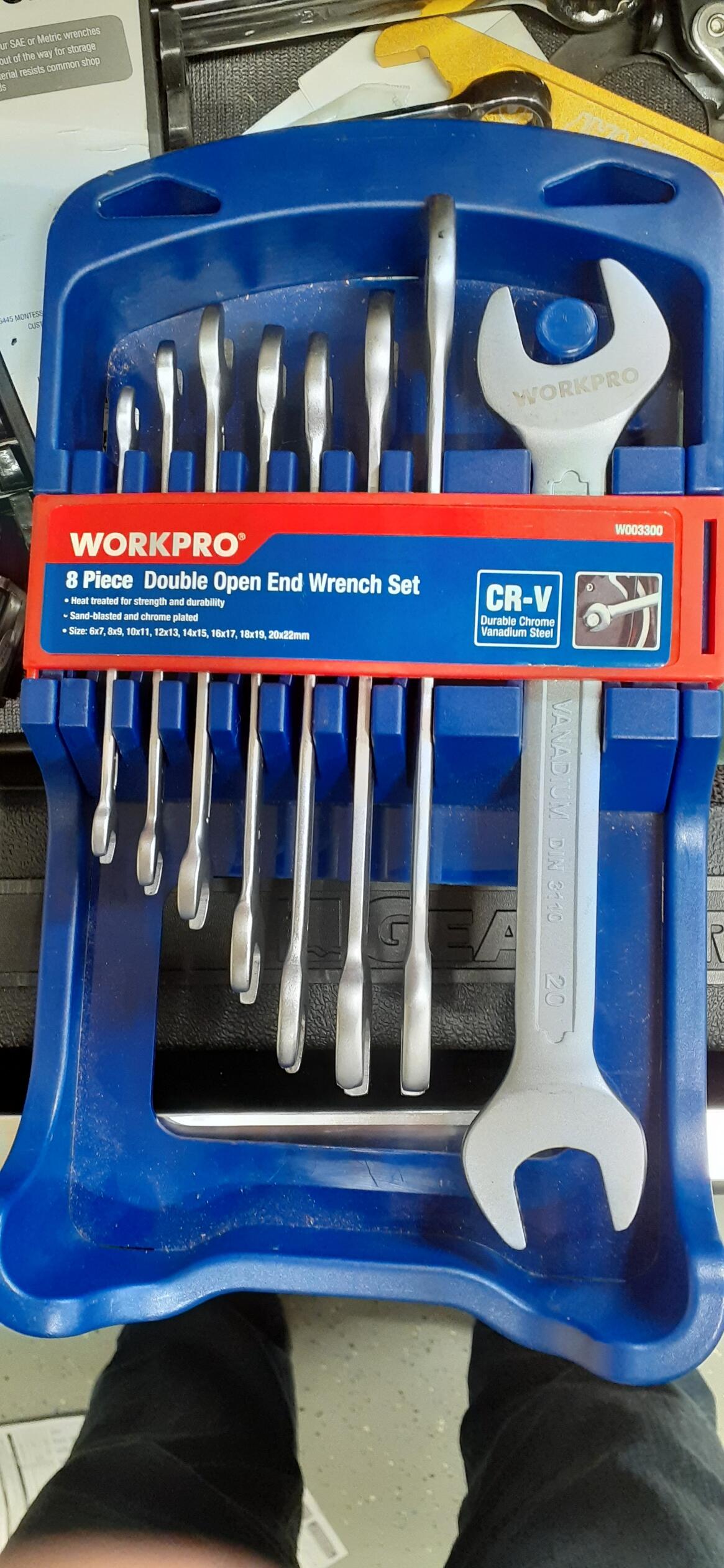
Lash pads are not the same as setting the valve lash. I can't speak to the technique to measure for the proper size lash pad, but maybe someone who does will chime in. This is the wrench set I like to use for adjusting the valve lash. They are not as thick as your typical wrenches, so it makes it easier to put both wrenches on the nuts for the valve adjustment. https://www.tme.com/us/en-us/details/wp-w003300we/wrenches-sets/workpro/w003300/

-
You measure valve lash with a feeler gauge. While there has been plenty of debate online about doing it hot or cold, you're definitely doing it cold. I hope your mechanic used properly sized lash pads. Use 0.008 for intake valves and 0.010 for exhaust valves.
-
If you still find them, Chevette springs can be cut to height. For some reason, there aren't a lot of choices available for a 40+ year old econobox. They give a much firmer ride, but I don't find them harsh or too stiff. The nice thing is that you can get 2 pairs of springs from Rockauto for $88 plus tax & shipping. The flip side is that you have to be willing to experiment to cut the springs the to right height. From re-reading the thread linked below, I guess I was aggressive with the amount I cut, but I'm happy with the results. I cut 3 from the rears and 2.75 from the fronts.
-
Pages BE-13 and BE-15 in the FSM cover these circuits. Common points of failure are the fuse box, the steering column connector connector where the green/blue and green/white wires pass between the dash harness and combo switch, and the combo switch. Unplug the steering column connector and check for voltage to ground at the green/blue wire on the dash harness side. It should always have battery voltage. Also examine the connector carefully for signs that it has overheated. I've seen many meltdowns at this connector. If you don't have voltage to ground, go back to the fuse box and test the voltage to ground on both sides of the fuse. The loose wires in the first photo are for the key buzzer. I'm not exactly sure where the second photo was taken, so I can't give an answer on those wires.
-
Where did you tap into for the voltmeter signal? There's a blue/red wire coming off the ignition switch and goes to the fuse box. It goes to the radio fuse coming out as a blue wire and the wiper fuse where it comes out as a blue/red wire. I'm guessing one of those wires, probably the blue wire is the signal for your voltmeter. If the blue/red is having intermittent contact to ground but not enough to blow the fuse, it could pull down the voltage on both circuits. Unfortunately you can't just pull the fuse for the wipers as that will also kill power for the reverse lamps.
-
It's the same part number in the parts catalog.
-
"Locking" means it is locking out the power switching circuit, so the coil never gets grounded. This is similar to why you don't want to leave the key in ON with the engine not running when you have points, only you are protecting other components.
-
And you can get them from a Nissan dealer, too, if you order part number 90522-E4100. https://www.courtesyparts.com/oem-parts/nissan-stopper-t-gate-90522e4100
-
Vintage connections has some good replacements for the connectors that use the spade style terminals. The round terminals for the gauges and dash harness to engine harness connectors were made by Yazaki (I think the spade connectors were, too.). Those connectors seem to be made of unobtanium, though you can get the terminals with different connectors from Eastern Beaver.