.JPG.cfcada9cf1c1b502df3f5f2f2ca3ff36.JPG)

SteveJ
Community Member
-
Joined
-
Last visited
Everything posted by SteveJ
-
Actually, your test results give me a different conclusion. The problem is upstream of the turn signal switch. Here is why I say this: The turn signals work. The hazard lights don't work. You have the proper resistance measurements at the switch. The jumper at the 6 pin connector was to eliminate the turn signal switch as being the problem. With the behavior being the same as with the switch connected, it reduces the chances that the switch is the problem. If the problem was downstream, the blinkers would have the same problem since they share the wiring from the switch to the taillights. The hazard lights and brake lights are powered off the same circuit. There is a good chance that there is corrosion or a damaged wire/connection in the circuit. Either condition is like a clog forming in the pipe between the water main and your house. If you measured water pressure with no faucets open, the pressure looks fine. However, run your washing machine, the shower, and the hall bathtub at the same time, and you will find you don't have any water pressure inside your house. So how do you find and remove the "clog" in your wiring? The easiest thing is to check your fuse box first. Look for corrosion or bent/poor contacts at the fuse. Look for corrosion or deteriorating contacts on the backside of the fuse box. Make sure the connectors between the dash harness and fuse box are in good condition and free of corrosion. Don't be afraid to take photos of your fuse box and post them here. I can only make "logical" guesses without seeing things or working with a meter on your car.
-
That makes more sense. You may want to get a terminal kit like this: https://www.amazon.com/gp/product/B07VKCCN12. It comes with a crimping tool. You could make a jumper with an inline fuse (See https://www.amazon.com/BOJACK-Holder-Inline-Values-Assortment/dp/B0813Q4S6P) and install it between the green/yellow and white/red (or white/black) wires on the dash harness side of the 6 pin connector. You could press the brake pedal to see if the brake lights on one side lights up. If the brake lights come on, then you can focus more on the turn signal switch. Also at the 6 pin connector on the turn signal switch measure resistance between the green/yellow wire and to the white/red wire. Repeat between the green/yellow and white/black. You should see close to zero ohms. If you have high resistance (or open line) that would indicate an issue with the turn signal switch.
-
Your response doesn't change what I said before. Do the tests I suggested and report the results. If the switch was reassembled properly, you should not see voltage at the green/yellow wire when the 6 pin connector is unplugged. The only way you would see voltage there with that connector unplugged is if it's cross-connected with the turn signals.
-
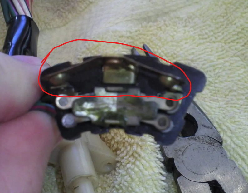
Did the brake lights ever work? Here is a breakdown of the circuit: https://fiddlingwithzcars.wordpress.com/2013/01/20/hazard-switch-brake-light-turn-signal-circuit-analysis/ Voltage measurements are a reference. Where are you putting your leads when you measure? There should not be any voltage on the green/yellow wire at the turn signal switch until the 6 pin connector is plugged in and the brake pedal is depressed. If you are seeing 12VDC to ground at the green/yellow wire when the pedal is not depressed or when the 6 pin connector is unplugged, that is a problem. With the 6 pin connector unplugged, check voltage to ground at the green/yellow wire on the dash harness side with the brake pedal depressed. Also bench test the turn signal switch with resistance readings. If the brake lights worked at one time but don't work now, my first guess is that the rocker for the brake lights is not making contact properly.
-
That looks like the Xenon air dam to me. They used to be about $160. Those days are gone.

-
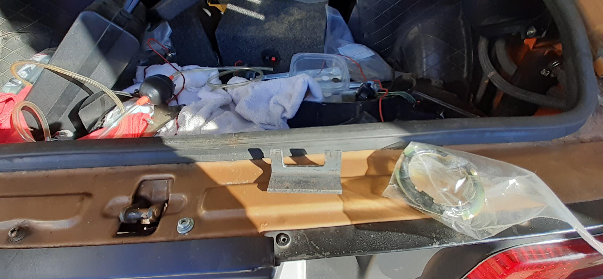
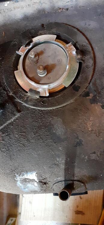
Here's the follow-up. I made a tool like @dmorales-bello did out of a Schedule 40 threaded cap. The downside is that it didn't fit with the tank strap in place. The good news is that the angle iron tool I made worked very well. It looks like I pinched the o-ring on the sender when I installed it. I used a new o-ring, and I haven't seen a leak. I tried the Dorman lock ring on my old tank. It had to rotate to the bump to have enough pressure to stop moving. I definitely prefer the Nissan lock rings, but it's good to know of alternatives should the good ones dry up.
-
I like that idea. It's easy to find the 2 inch pipe and caps in iron around here. I didn't want to use the screwdriver and hammer because the tank is in the car and half full of gas. I have an aversion to mixing sparks and gasoline vapors. I found it. I like that idea, too.
-
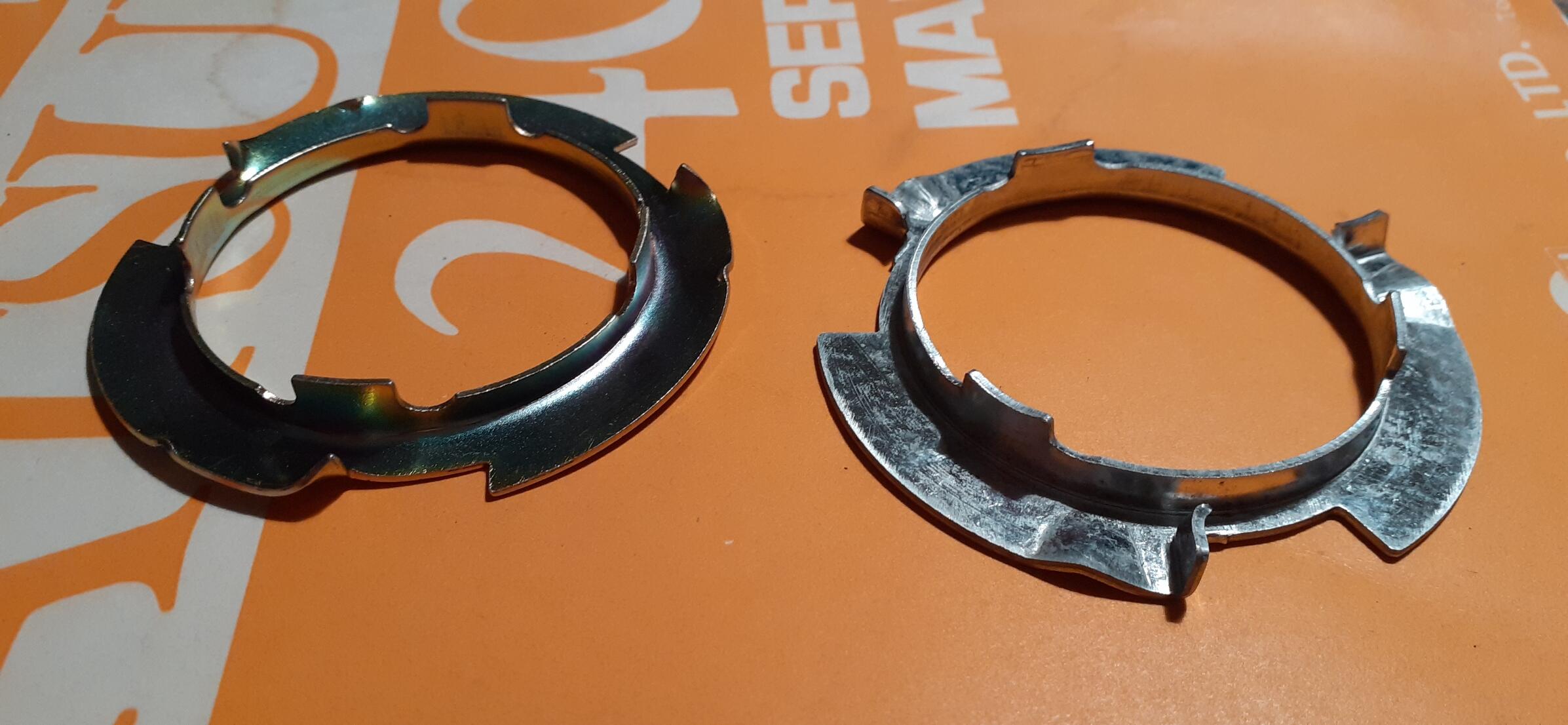
I need to remove the lock ring from the 240Z fuel tank, and I thought I would do a search to see if there is a tool to do that. Google sent me down several interesting rabbit holes in this quest. I noticed that the lock ring for the older Mustangs looked pretty similar to the one for the 240Z. That ring was cheap, so I ordered one. It is slightly larger than the 240Z ring. Many older GM cars/trucks have a very similar style and size, too. The locking ring tools may work, but I didn't feel like ordering one. Here are a couple I found: http://blog.virginiaclassicmustang.com/2020/09/gas-tank-sending-unit-lock-ring-tool.html https://www.ecklers.com/fuel-sending-unit-lock-ring-tool-25-255042-1.html One of the other rabbit holes I explored was the Honda/Acura lock ring from the 90s. Once I found the Ford lock ring was too large, I thought that the Honda one might be closer due to metric system stuff. I found the Dorman 579-015 on Amazon: https://www.amazon.com/dp/B002D3Y30U. At that price, I figured it was worth a look. A new Z lock ring from ZCarDepot is on the left. The Honda lock ring seems to have the same inner and outer diameters as the Z lock ring. It only has 3 inner tabs as opposed to the 4 on the Z lock ring. I plan on trying the lock ring on an old tank in the near future to verify fit. Given that the 240Z lock rings are cheaper, there isn't a need to switch, but we never know when supply will dry up. As for a lock ring tool, I decided to make one myself. A friend who has worked on a lot more Z cars than I have told me he made a similar one.


-
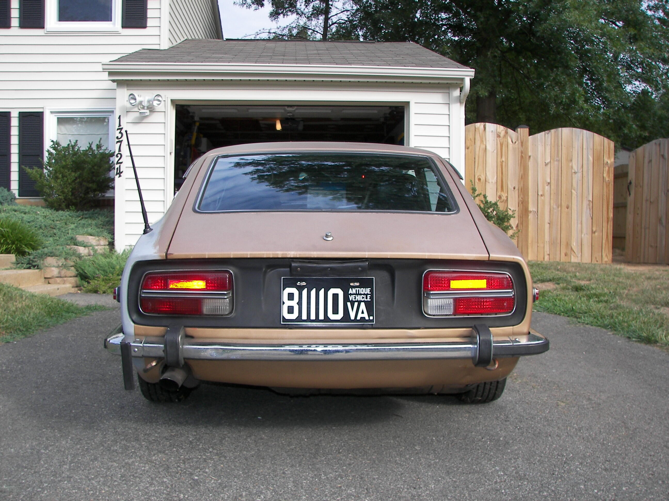
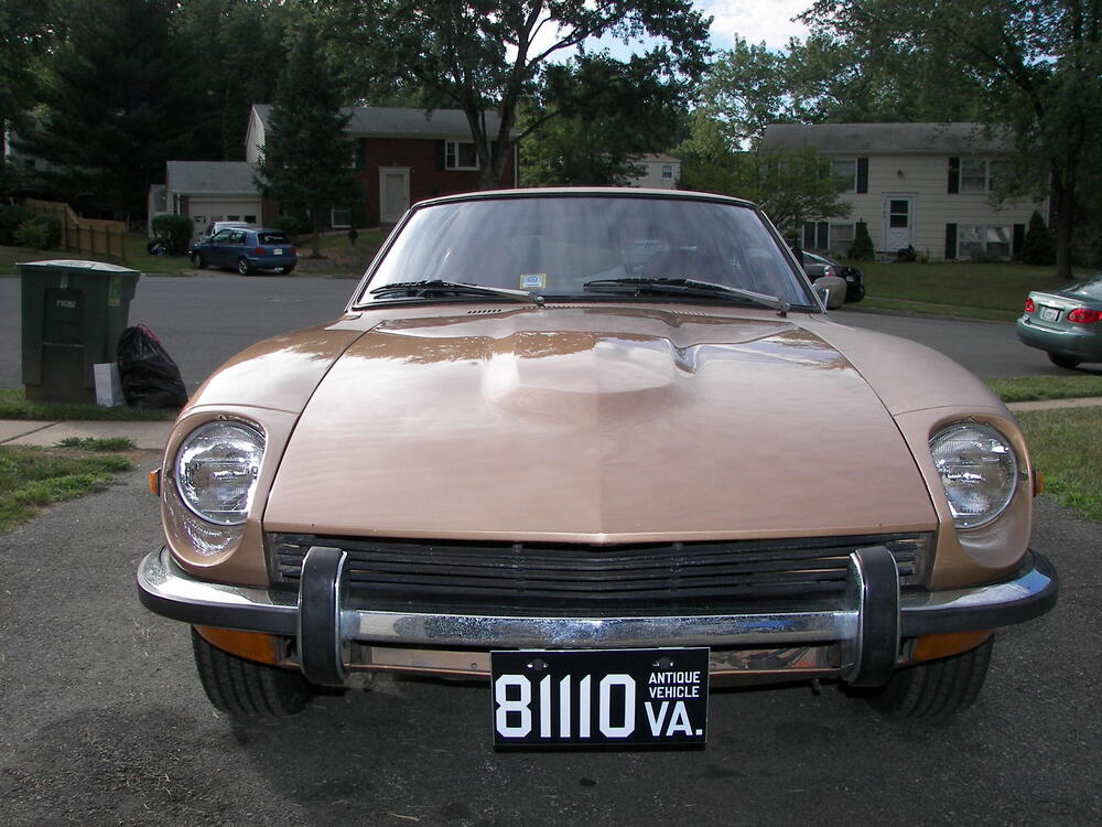
I found an old memory card while rummaging through a desk drawer today, and it had some photos I took of the 73 before I had it shipped from Virginia down to Georgia.

-
The rebuild kit is cheap compared to finding yourself getting a tow truck after one of the recent aftermarket fuel pumps fail.
-
In the Hagerty emails: https://www.hagerty.com/media/news/garage-find-datsun-240z-looks-like-a-complete-project/?utm_source=SFMC&utm_medium=email&utm_content=MED_UN_NA_EML_UN_DailyDriver_Wednesday&hashed_email=9349c1d026c1a6565d70def8ee2cc14d84a280918073cb399a3779bff82734f8 The ebay link said reserve not met at $21,700.
-
So, I have experimented a lot with different LED headlights. The current setup in my 260Z is H4 housings (the old Black Dragon H4s) with Auxito H4 9003 LED Headlights, https://www.amazon.com/gp/product/B07TQLK6SH. Those bulbs can be combined with about any H4 housings, such as Hella. They throw out a lot of useful light, especially on high beams. It's a reasonably economic solution, and the bulbs are polarity independent.
-
I had moved my brain down below the waist well before that since that was how I was doing most of my thinking back then...
-
I can pull the rear struts without touching the spindle pins. Detach the half shaft from the wheel & rear sway bar and you can swing the control arm down and out of the way. Of course, you'll need a good size lever to swing the arm down.
-
Chance favors the prepared.
-
If you don't know what you're doing, yes. The coil springs have a lot of stored energy, and typically you compress them to get the struts free, increasing the stored energy. If you aren't careful, they can come apart with great force. I had that happen to me once, but I avoided serious injury by having it hit me in the head. Seriously, the strut popped out of the spring compressor, and the spring struck me right at the eyebrow. It sliced me open, but fortunately that's a pretty stout area of the skull, so I escaped serious injury. Since it was on a military base, I got a free ride in an ambulance, too! Watch videos on changing out the struts. If you REALLY want to do them yourself, find a friend who is knowledgeable on the procedure supervise you. There is a trick to pull the front struts without breaking open the brake line, but it's not for the faint of heart. (Most instructions have you taking the soft line off the S-tube.) You'll have to take the brake lines off the rears to remove the struts. All this means that you'll be needing to bleed the brakes, too. This includes bleeding the master cylinder.
-
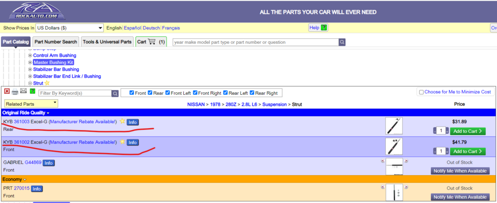
Rockauto The second link in your post was for a 280ZX. Those would not work on a 78. The price from Rockauto would be better than the other ebay link, plus there is a rebate available if you buy before 12/31.
-
Maybe a kit like this would work: https://www.amazon.com/dp/B087WNSDPV/
-
I believe I put some RTV on some shorter bolts and sealed the holes that way.
-
How long did it take you to clean the seats after feeling something furry there?
-
It ain't cheap, but it is available now: https://s30.world/product/01-77-till-12-78-datsun-280z-fairlady-z-fuel-tank-vapor
-
Here's one I purchased 5 years ago https://www.amazon.com/gp/product/B00PWNQMYI
-
Here's one way to check for leaks. Build a smoke machine. Start with the link below and work your way down the thread. I included a link to the YouTube video I used as a basis of design. Take off the valve cover. Rotate the engine so the intake valve on one of the front 3 cylinders is open. The cam lob for the intake valve will be down, and you can tell which are the intake valves because they line up with runners on the intake manifold. Remove the spark plug for that cylinder and plug in the smoke machine. Have someone push smoke through the cylinder while you're on the other side looking for leaks. If you have to do this solo, figure out how to set up your phone to take video of the manifold while you push smoke through. You may have to do this for each of the front three cylinders.
-
I chatted with him on the phone. I think he'll get it straight now.
-
I don't know if the C-Springs club ever formed, but there is the Z Car Club of Colorado. https://www.zccc.org/