


Namerow
Community Member
-
Joined
-
Last visited
Everything posted by Namerow
-
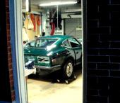
Sorry, but what kind of car is this?
-
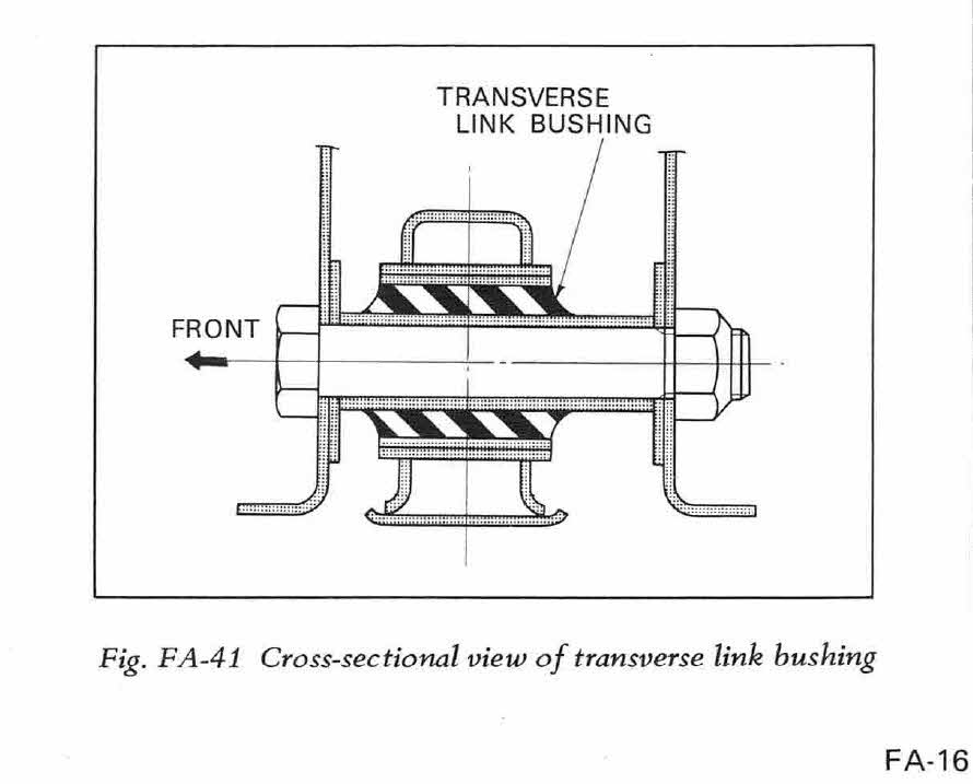
The FSM diagram that Zedhead posted is from the 280Z manual, so it's possible that the bolts used for the 240 were stepped rather than tapered. The fact that Nissan's engineers chose to use a stepped/tapered design rather than a plain old bolt says to me that there's a lot more going on here, NVH-wise, than first meets the eye. The m-bar 'bolts' are more like pins with threaded ends. It's an expensive design (compared to a bolt), so it was used for a reason (just like those rubber-ribbed end-washers) It's a little hard to tell from the FSM sectional diagram, but it appears that only the upper 'special washer' (as the parts manual calls them) bears directly on the shoulder of the pin in the radial direction. If I'm right, it means that the 'eye' of the m-bar is solidly located (in the radial direction) only at the top, while the bottom 'floats' (in the radial direction) on the rubber of the lower special washer. It also means that the thick rubber of the big bushing only comes into play (in the radial direction) when the m-bar deflects far enough to bring the inner metal sleeve of the bushing into contact with the pin. My guess is that this is all about isolating high-frequency differential/gear noise from the chassis under light-load/cruise conditions (via the ribbed special washer), with the bushing only coming into play (laterally) to isolate against cornering-induced vibration (when the diff loads up laterally against the pins). Kind of a two-step isolator for lateral loads. In the vertical plane, the special washers and the bushing look they work in unison as a two-mode isolator (that is, they're both at work simultaneously, in series, but have different stiffnesses and natural frequencies and therefore serve to isolate different vibrational frequencies). Another interesting point (to me, anyway): the FSM refers to the m-bar as a 'transverse leaf spring'. That suggests that the bar itself is being used as a spring. The m-bar is only truly flexible in the fore-aft direction, so perhaps it comes into play when the diff is subjected to braking loads. One final thought: All of this suggests to me that it's not a good idea to jack up the rear of the car using the diff casing.
-
here you go...
-
from Wikipedia... Hydrogenated nitrile butadiene rubber (HNBR) is widely known for its physical strength and retention of properties after long-term exposure to heat, oil and chemicals. Trade names include Zhanber (Lianda Corporation), Therban (Arlanxeo [5]) and Zetpol (Zeon Chemical). Depending on filler selection and loading, HNBR compounds typically have tensile strengths of 20–31 MPa when measured at 23 °C. Compounding techniques allow for HNBR to be used over a broad temperature range, -40 °C to 165 °C, with minimal degradation over long periods of time. As a group, HNBR elastomers have excellent resistance to common automotive fluids (e.g., engine oil, coolant, fuel, etc.) and many industrial chemicals. The unique properties and higher temperature rating attributed to HNBR when compared to NBR has resulted in wide adoption of HNBR in automotive, industrial, and assorted, performance-demanding applications. On a volume basis, the automotive market is the largest consumer, using HNBR for a host of dynamic and static seals, hoses, and belts. HNBR has also been widely employed in industrial sealing for oil field exploration and processing, as well as rolls for steel and paper mills.
-
Happy hunting, CO! Still hoping that someone can post those three measurements for the Nissan OE bushing so that we've got a reference point to work from...
-
Thinking out loud here... Has anyone ever checked to see whether any of the other, still-available Nissan steel-sleeved isolator bushings could be adapted to the moustache bar? The make-or-break dimension would be the outside diameter of the external sleeve, which would need to be pretty much spot-on. Length could be trimmed to suit (or two under-length bushes could be stacked and then cut to length). Inside diameter of the inner sleeve would only need to be within 10%, I would think (could be sleeved up, but not the opposite). The S30 bushes that come to mind are the spindle pin bushes, the front control arm inboard pivot, and the transmission mount. I have all three on hand and can provide their measurements. What I don't have are the the three key dimensions for the moustache bar bushings: Length Outside dia. of the outer sleeve Inside dia. of the inner sleeve Anybody? Even if none of the other S30 bushes will work, there are hundreds of steel-sleeved bushings out there on the market. Captain Obvious has shown an appetite for looking through online parts catalogs, so with the right dimensions in hand, maybe we (I mean, Captain Obvious ) can find a suitable replacement for the NLA Nissan parts. As for the wavy-shaped rubber end washers, I think suitable facsimiles could be cobbled up pretty easily from thick rubber washers, using a small-diameter sanding drum in a Dremel. Fiddly work, but would probably only take 30 minutes to make four. An alternative fab strategy would be to drill a set of radial holes through a double-thickness rubber washer and then slice it in half, creating a pair of the desired washers in the process. The biggest challenge here would be finding the right rubber washer to start with.
-
Grannyknot's other nickname is, 'Teddy The Torch'.
-
Sometimes the obvious escapes us all . Now that you know the 'secret', it should be much easier. You'll need to use vise-grips to get a firm hold on the free clip so that you can pull against the strap tension and navigate the pins into their holes in the seat frame tube. When it comes to making the cuts in the strapping, this is a classic case of, 'measure twice, cut once'. One mistake and you'll be feeding more $$ into the coffers of MSA to order another strapping kit.
-
hmmm... I don't think you're going to like the results if you replace the straps with a metal plate. At least, not unless all the roads where you live are billiard-table smooth. The strapping kit isn't that hard to install. The three fore-aft straps all get cut to the same length. The MSA kit provides you with the details and includes enough webbing to do both seats with about 6" left over (which means there's no forgiveness if you screw up on any of your cuts). When cut to the correct length, you don't really have to stretch the straps very much to seat the end clips into the seat frame. I found the most difficult step was punching holes through the straps for the rivets to pass through. That rubberized webbing is tough! When you're installing the end clips on each strap, make sure they're both facing the same way up before you install the rivets (it's no fun trying to remove the rivets to fix a mistake made here). If you work at it methodically, you should be able to complete the strapping job for both seats in a morning or an afternoon.
-
Did you find your o-a torch head yet? p.s. Thx again for the help with the brazing. After I dressed down the two ports, the manifold went back in the blast cabinet to clean it up again, after which ti got a coat of VHT primer. Needs to cure for a week before I can do the finish coat. I was tempted by your idea of sawing off the nut heads and tapping the holes to take some nice, shiny brass plugs... but I got over it.
-
For more insights, try a Google street view of his business address I think he's just a re-seller. And not a very good one, it seems.
-
I wonder if the specialist company that rebuilds harmonic balancers (I've forgotten the name and location) would be interested in taking this on? Same basic principal. It's pretty clear that a solid urethane bush is not going to produce the same result as a webbed rubber bush. And I don't think the serrated end washers were added by the Nissan engineers just becuase they looked cool.
-
-
Glad to hear things are working properly. I think if you did a search on this site, you'd probably find a couple of dozen threads that start with the words, 'Can anybody tell me what this ___ (insert color) wire is for?' It seems that most Z's fell prey to D-I-Y AM/FM/cassette player installers at one time or another, all of whom went looking for a power wire to tap into.
-
Nope. The 'S' terminal becomes and stays 'live' over the full range of key travel in the 'Start' position. Same for both switches. I don't necessarily disagree that there might be something wrong with the internals of my Beck & Arnley switch, but the housing halves are staked closed so I'm not interested in try to get it apart to see what might be going on. Maybe somebody else has got an aftermarket 240 ignition switch lying around loose that they could try the same experiment with. Just to satisfy my curiosity.
-
-
Nope. Nothing's loose. The detent for the Start position (for either switch) isn't a 'click-stop' detent like the other positions. The Start detent actually provides 5 or so degrees of key travel before the key runs up against a hard stop. During that travel, the key rotation is resisted by an internal spring. It's something you probably wouldn't notice when you're doing a normal engine start, but you'll notice it right away if you try operating the key with the battery disconnected. It's probably there to provide a cushioned stop for the key when the operator is extra-energetic about trying to get the engine started.
-
-
I have a question for the electrical experts: I bought a Beck Arnley aftermarket ignition switch to replace the 40-year-old OE switch in my '70 Z. Seemed like a good preventative maintenance step, with the steering column currently out of the car. However, I've found puzzling difference in the operating logic of the two switches. It has to do with the switches' 'R' circuit, which I'm pretty sure means, 'Resistor' (as in, ballast resistor for the coil/tach circuit). With input power applied to each switch module by way of the 'B' (battery) terminal and output monitored at the 'R' terminal, this is what I find: Key Position "R' - OE Switch 'R' - Aftermarket Switch OFF dead dead ACC dead dead ON dead dead START live live to start, then goes dead when key is turned further against the detent spring It's been noted elsewhere that the Z's ignition circuitry is designed so that the ballast resistor is bypassed during engine start (so as to deliver higher voltage to the coil/points) and then brought back into the circuit during 'run' operation (so as to operate the points/coil at the lower, normal voltage). So a 'live' condition at the 'R' terminal of the switch means 'resistor out', whereas a 'dead' condition equates to 'resistor in'. My OE ignition switch adheres to this simple, two-step 'resistor out/resistor in' logic. The aftermarket switch does too... at first. But then as I twist the key a little further in the 'START' sector, working against the resistance of the internal spring to take the key all the way to the hard stop, the switch action reverts to 'resistor out'. This would typically be where the key would sit while cranking the engine (i.e. twisted all the way up to the hard stop) I'm not certain whether the aftermarket switch was designed this way on purpose, or not. There's also the possibility that it's just a defective unit. So now I'm not sure whether I want to use it. Does anybody have an idea about why the aftermarket switch would change from 'resistor out' to 'resistor in' halfway through the 'Start' segment? Could it be that this was done on purpose, so that the duration of the high voltage ('resistor out') condition in the coil/points circuit would be restricted to just the first part-rotation of the crankshaft, so as to avoid burning the points during prolonged cranking?
-
I have a rebuild kit on order from MSA. When I get the chance to have a look at it, I'll let you know whether the two seals are identical vs. different.
-
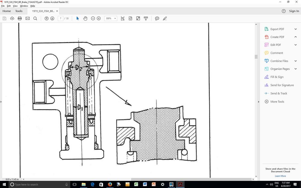
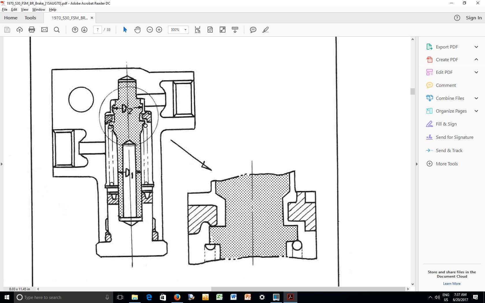
Good to hear... but I'd still like to know how a proportioning valve turned into a no-flow valve. The more I study the FSM (see below), the more it seems to me that the 'upper' seal is critical to the way the valve works. It appears to have a unique cross-sectional shape. Maybe you installed it upside down?
-
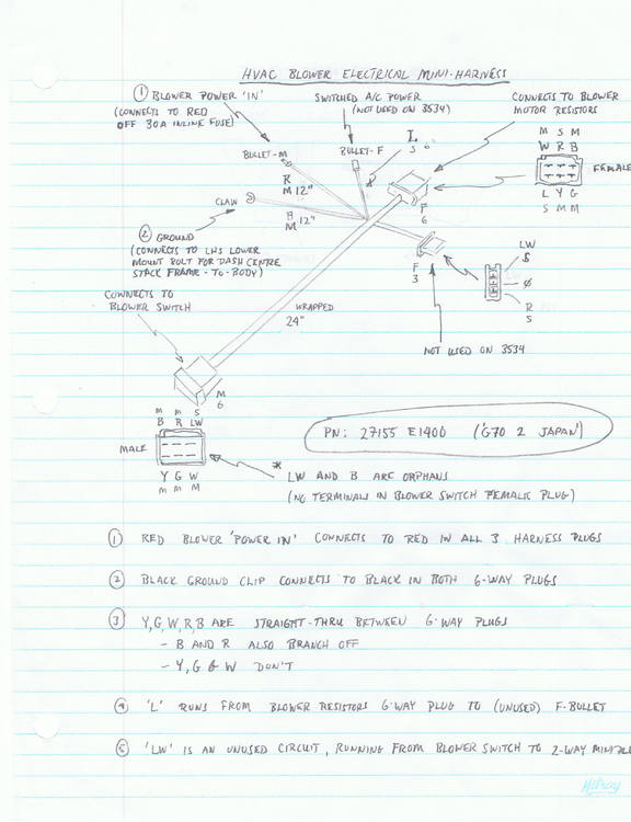
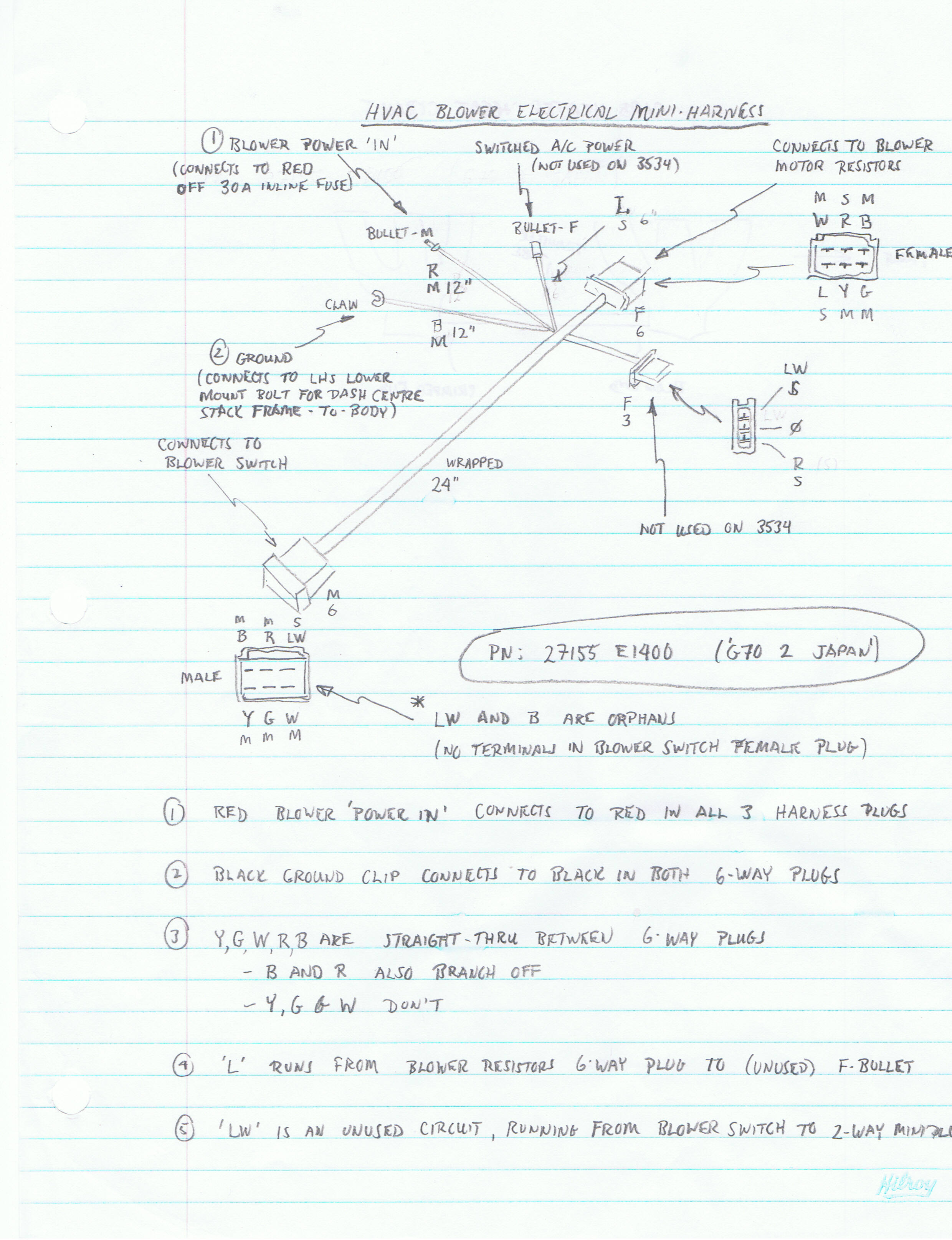
The elusive HVAC mini-harness is lurking in the bottom right corner of Fig. 1.2 in the FSM Supplement that CO has posted. It also appears in the bottom right corner of Figure VI-1 at the end of the FSM Supplement, complete with some labeling and a legend with some wire color coding to (sort of) tell you where some of its connections connect to. The blue wire is, according to the legend, there to provide a power signal to the A/C system... which was, of course, available only as a dealer-installed option, meaning that for many Z's the blue wire never ended up being connected to anything over the life of the car. When it came from the factory, the blue wire ended in a female 'bullet' connector. I've scanned the notes I made for the HVAC mini-harness and they appear below... (note: everything you see in my notes is specific to a 1970 Z with manual trans):
.thumb.jpg.65ad2d812299c8f3b47c81ea70cad6f1.jpg)
-
Thanks, Mark. Based on your comments, I tried the vice-and-socket routine again and this time I was able to get one of the cups free -- from the shaft-side yoke. But that was it, so out came the cut-off wheel (fortunately, the spider had shifted far enough to one aside to let me get the cut-off disc into the gap without damaging the inner face of the yoke). After using the cut-off wheel, I was able to separate the shaft from the splined yoke, which made subsequent work a bit easier. I had to cut both legs off the spider to get it out of the splined yoke. Even after I'd extracted the remains, there still was one cup that refused to budge more than about 1/32" in either direction. Sixty seconds with a MAP torch got the yoke hot enough so I could tap out the cup with a punch. Additional comments for anyone else trying this: For each of the two yokes, I found that one of the two cups would not move inward (and, yes, all the retaining clips had been removed). That meant that my press-out efforts with the vise and sockets would only work in one direction. Even in the successful direction, there was a loud 'crack' before the cups started to move. Instead of using an oversize socket on the exit side of each yoke, I ended up grabbing some 1x2 hardwood scrap and drilling a hole in it (11/16" drill, if you do this). Thew wood piece could then be propped up inside the vise jaws to the right height and then sit there without needing a hand to hold it in position. It was then much easier to juggle the combination of the other socket, the steering shaft and the vise handle while trying to get everything aligned and the vise jaws tightened down enough to hold everything in place. I think I'm going deep-freeze the new spiders and cups and then use a torch to get some heat into the yokes before I try re-assembly with my new Kawasaki U-joint kit. The cups look like they'll be really easy to get cocked a bit sideways at the start and I don't want to risk chewing up the bores.
-
I'm digging up an old post, but the topic is a current one for me and I know that Z-Cars probably isn't too far away... Jim: You said that the spider for the steering shaft U-joint can't be removed by a straight press-out, but you made this comment in reference to the later, staked-type U-joint. In an earlier post in this same topic, though, you'd said that you'd replaced one of the earlier-design, circlip-type U-joints and commented on what an easy job it was. Well, my 70 Z's steering shaft has the circlip-type U-joint and I'm having the interference problem that you mentioned in reference to the staked-type U-joint. My question: Were you really able to press out the spider on the circlip-type U-joint, or did you have to cut that one out too?
-
I may be difficult to replicate one of these tags to OE standards... The plate itself is made from stamped-out piece of aluminum sheet The black top coat has a satin-ish semi-gloss appearance, with a barely noticable top-to-bottom 'grain' The 'HLS30' characters were produced by leaving the shiny top surface of the aluminum plate stock exposed. The characters have no 'lip' around their edges (i.e. the entire top surface feels smooth), so the black overcoat must be just mil's thick. Masking and painting won't replicate this. I think the overall process used originally would have consisted of some kind of silkscreening. Maybe somebody else with experience in a print or photography shop knows better. The five (or six) digit VIN numerals were produced by the die punch cutting through the black top surface of the plate and penetrating into the underlying aluminum. There doesn't appear to have been any paint used to highlight the 'trench'. Once again, what you see is the exposed aluminum of the underlying plate stock. You'll need to find a metric number punch set with the correct font style (?) and the correct size (seems to be 7mm x 4mm). It sounds to me like Mike at Banzai has priced this out quite fairly at $450 (to do it right). If that's too steep for your budget, maybe you could just use the VIN tag that Grannyknot has sent you. Given the car's salvage-title history, it would seem to be mainly just for show (although your local constabulary may not share this view). The VIN that's stamped into the firewall is the definitive identifier of the vehicle and it should be backed up by the number stamped into the plate in the engine bay.

.jpg.ea68db7982521082c66f98df5f3b9454.jpg)