HusseinHolland
Community Member
-
Joined
-
Last visited
Everything posted by HusseinHolland
-
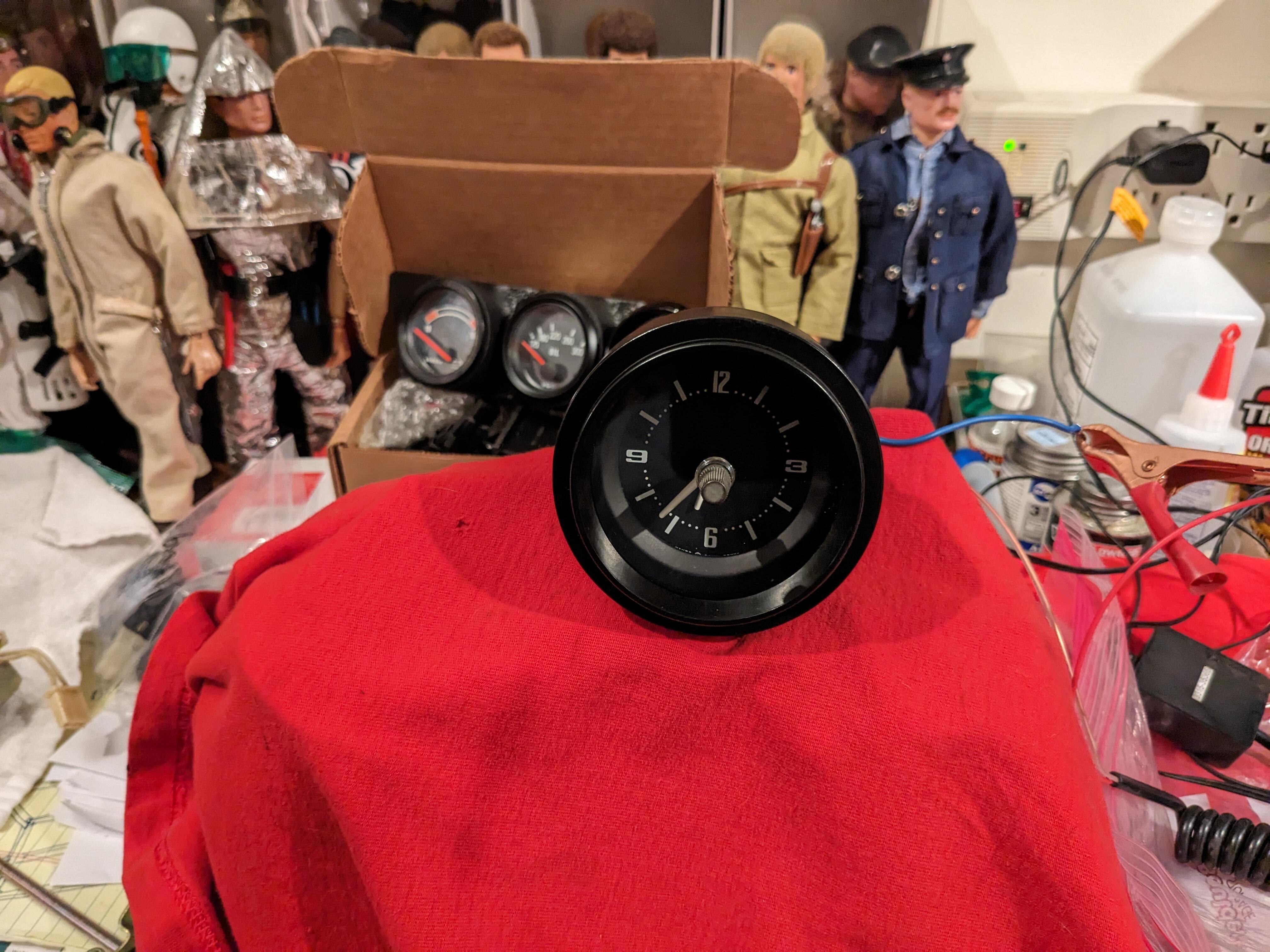
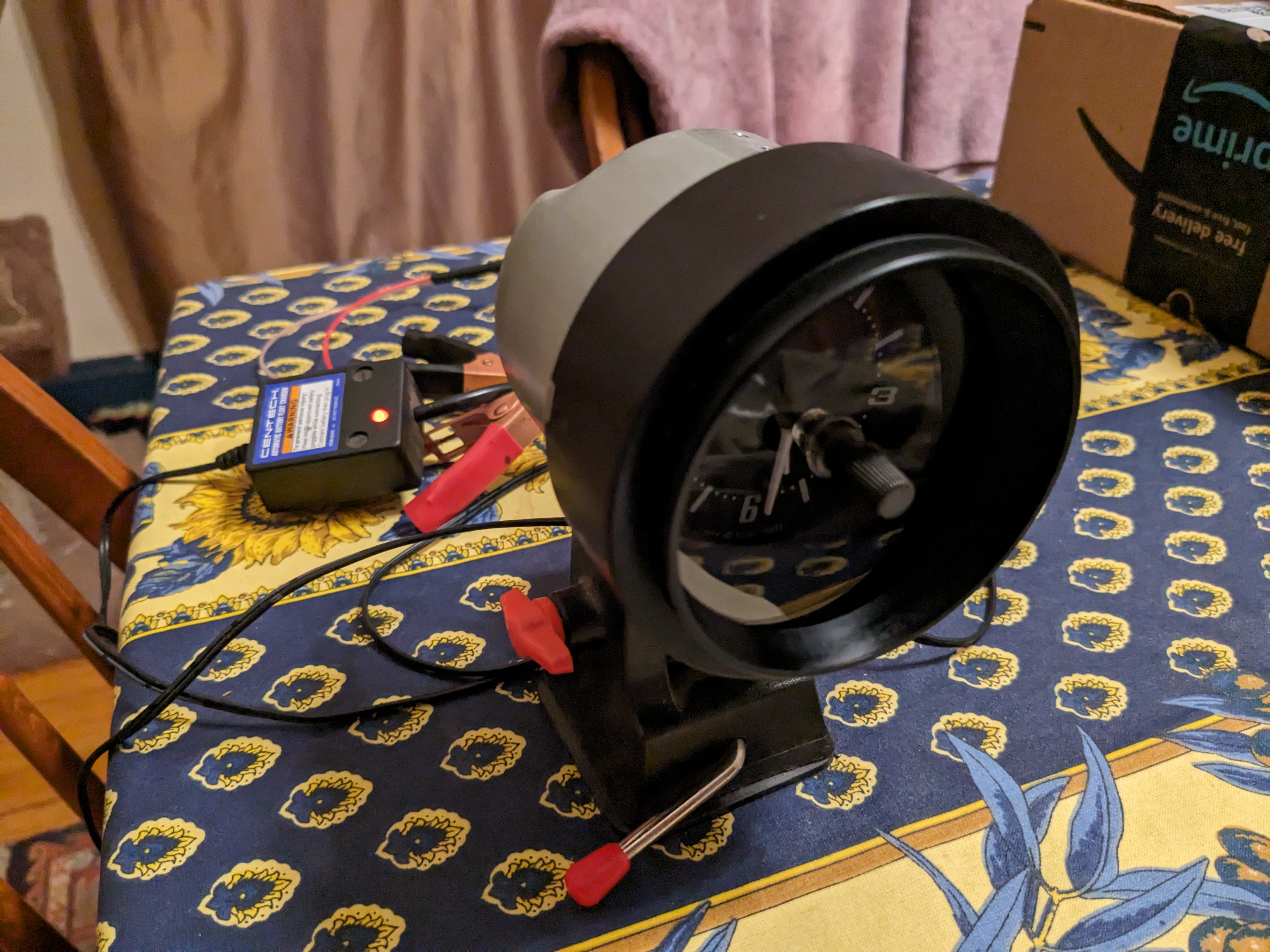
So, I have the clock sitting on a shelf running. It loses about 5min over 48 hours. There is an speed adjustment marked S & F. Question is, doesn't that mean rotate toward S to slow it down, and toward F to speed it up, or vice-versa?

-
Did you mean to post in the bulb socket thread? 🙂
-
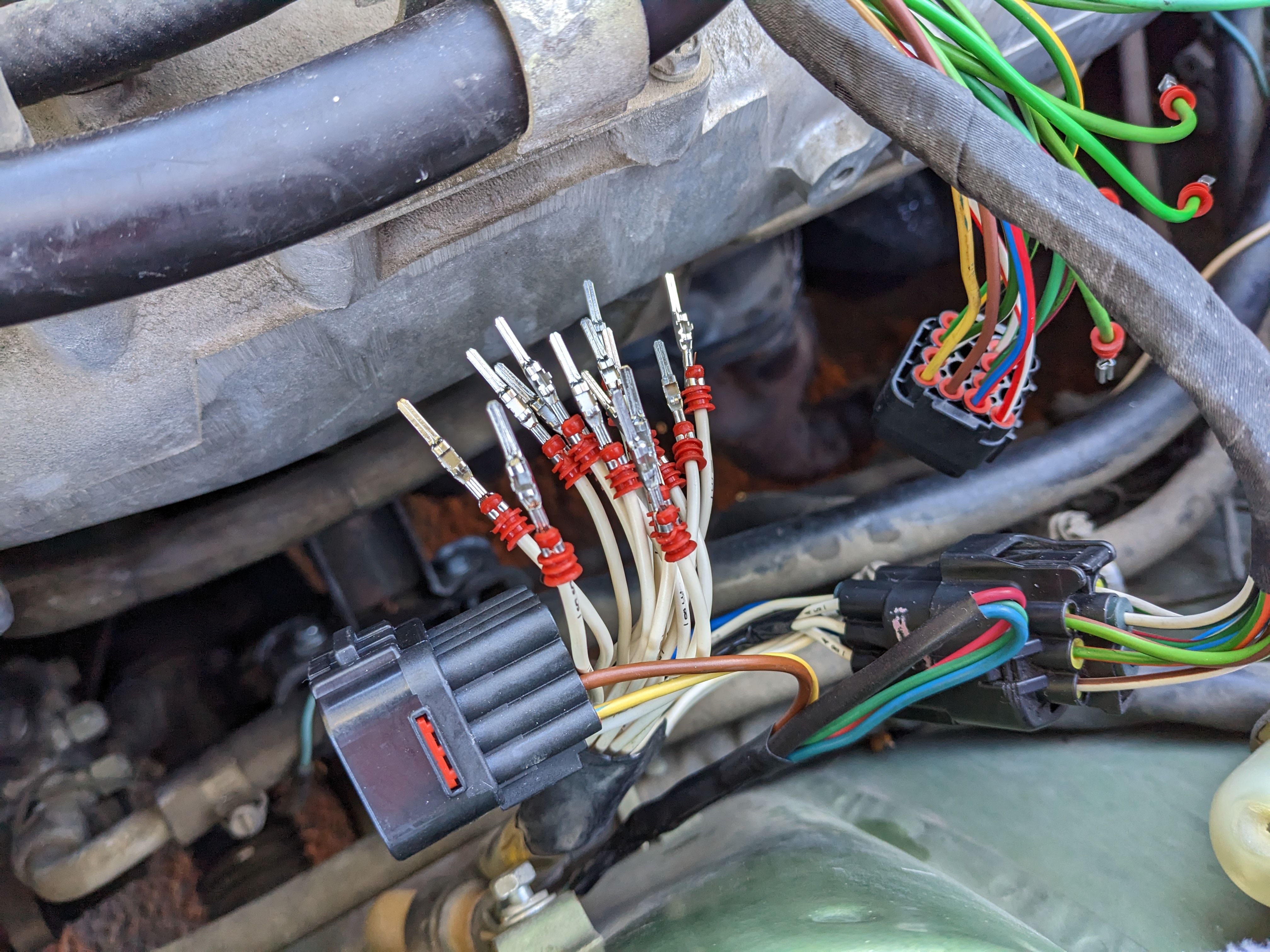
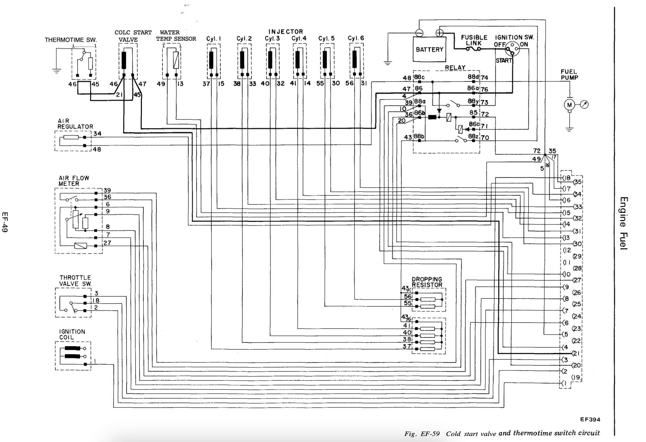
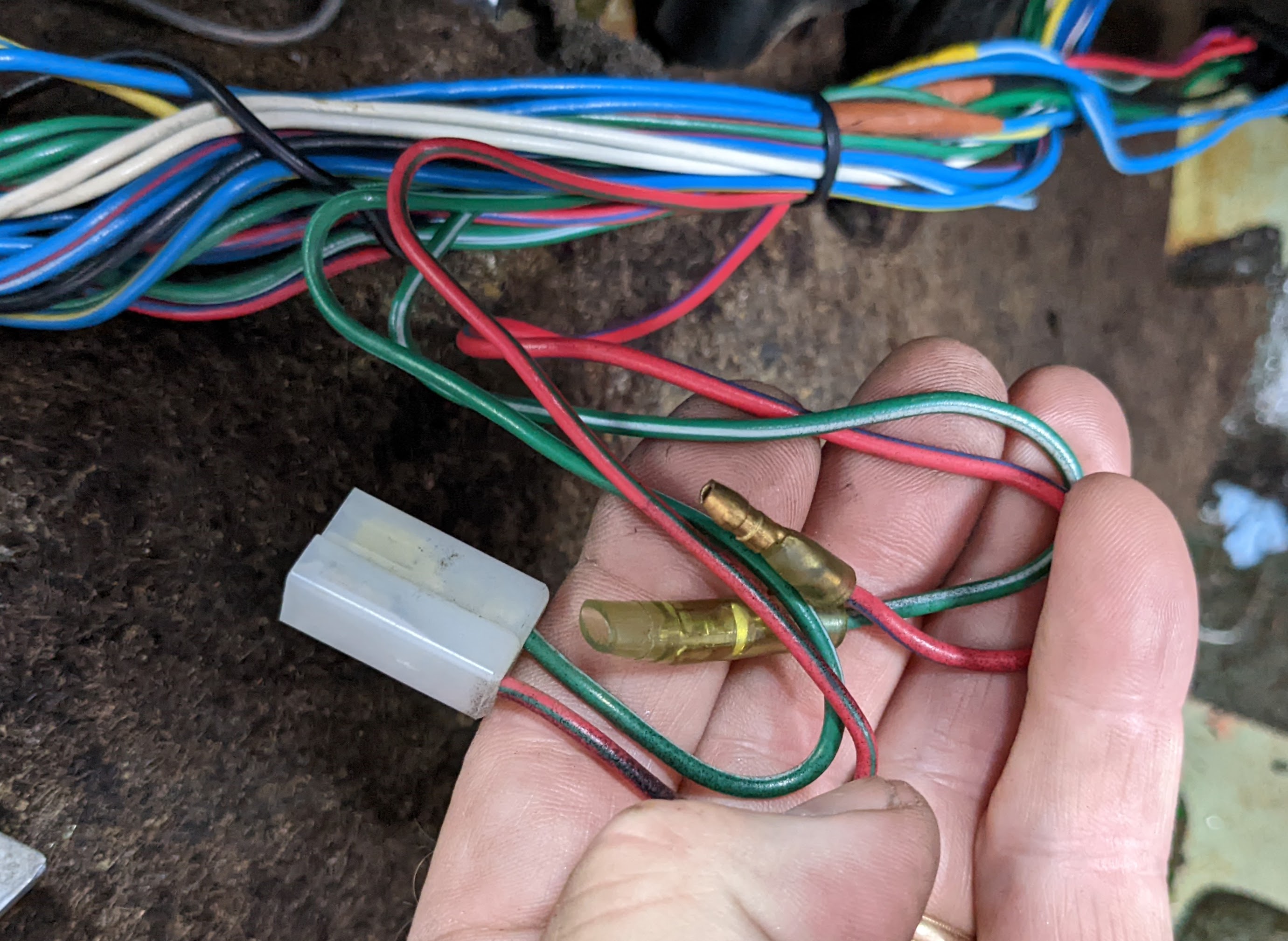
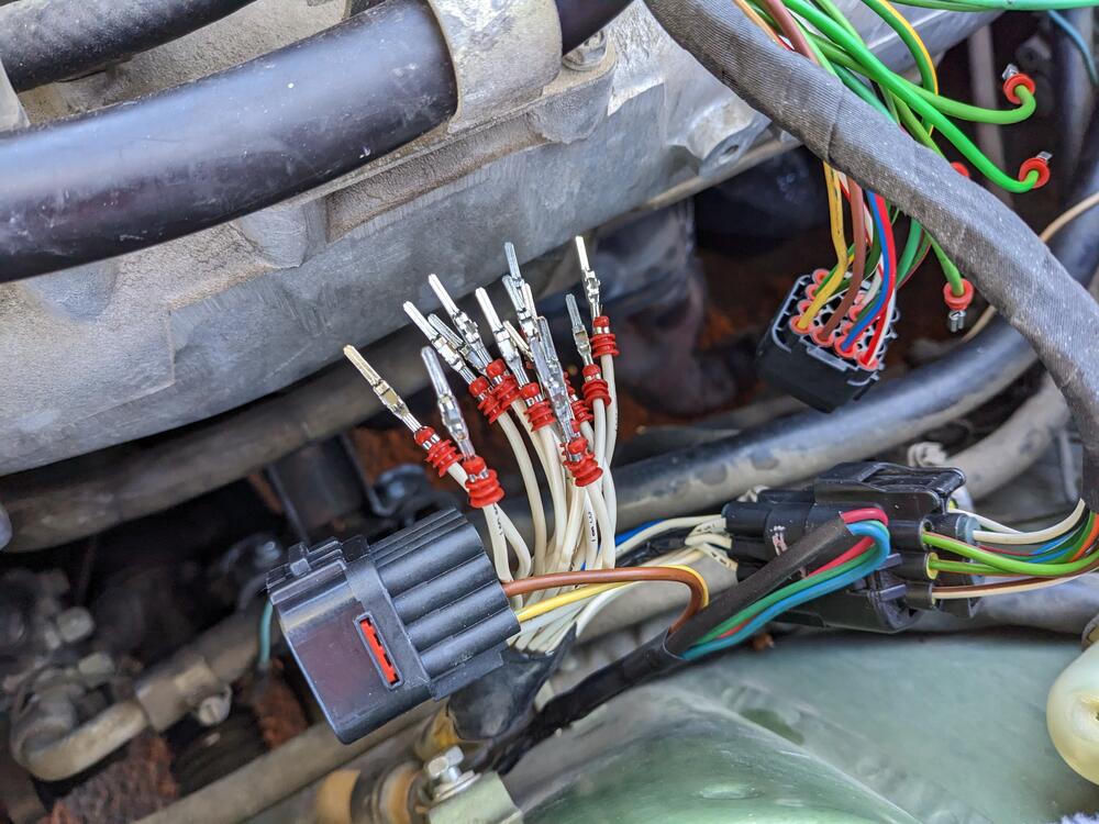
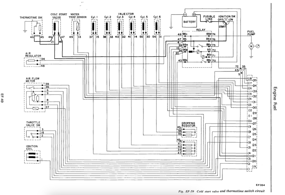
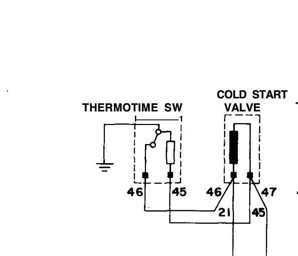
So, now that the ambient temps have dropped, I see that the cold start system is not actually operational. When I rewired the EFI harness I found the ECT & TTS were mis-wired. I don't know if that caused an issue at the ECU. In any event, I bridged the TTS connector, and have voltage output from the EFI relay 86 terminal to the cold start valve when cranking (checked with test lamp on pin 86 at relay, and 45 at CSV.) I confirmed the CSV functions by powering & grounding the CSV to the battery with the fuel system pressurized. The CSV does not inject fuel however, and if I put the test light across the pins of the connector, it does not light, which would indicate to me that the ground side of the circuit is non-functional. I tested the continuity of the harness from the TTS connector (pin 46) and the CSV connector (pin 46) and both have continuity back to the harness plug I made. Tomorrow I'll have to check the continuity of the ground side of the harness from there back to the ECU connector. My question is, does anyone have experience with this aspect of the system that would indicate a common failure point? The wiring diagram is not accurate in terms of the actual wiring of this circuit - the bridge circuit for the TTS in not at the CSV, is it back in the harness on the inner fender, where 47 is T'd off into to 45 wires, and 21 is T'd into 2 46 wires. I discovered that when I did the re-wiring.
-
Thank you Steve! I ordered those to see if they fit OK.
-
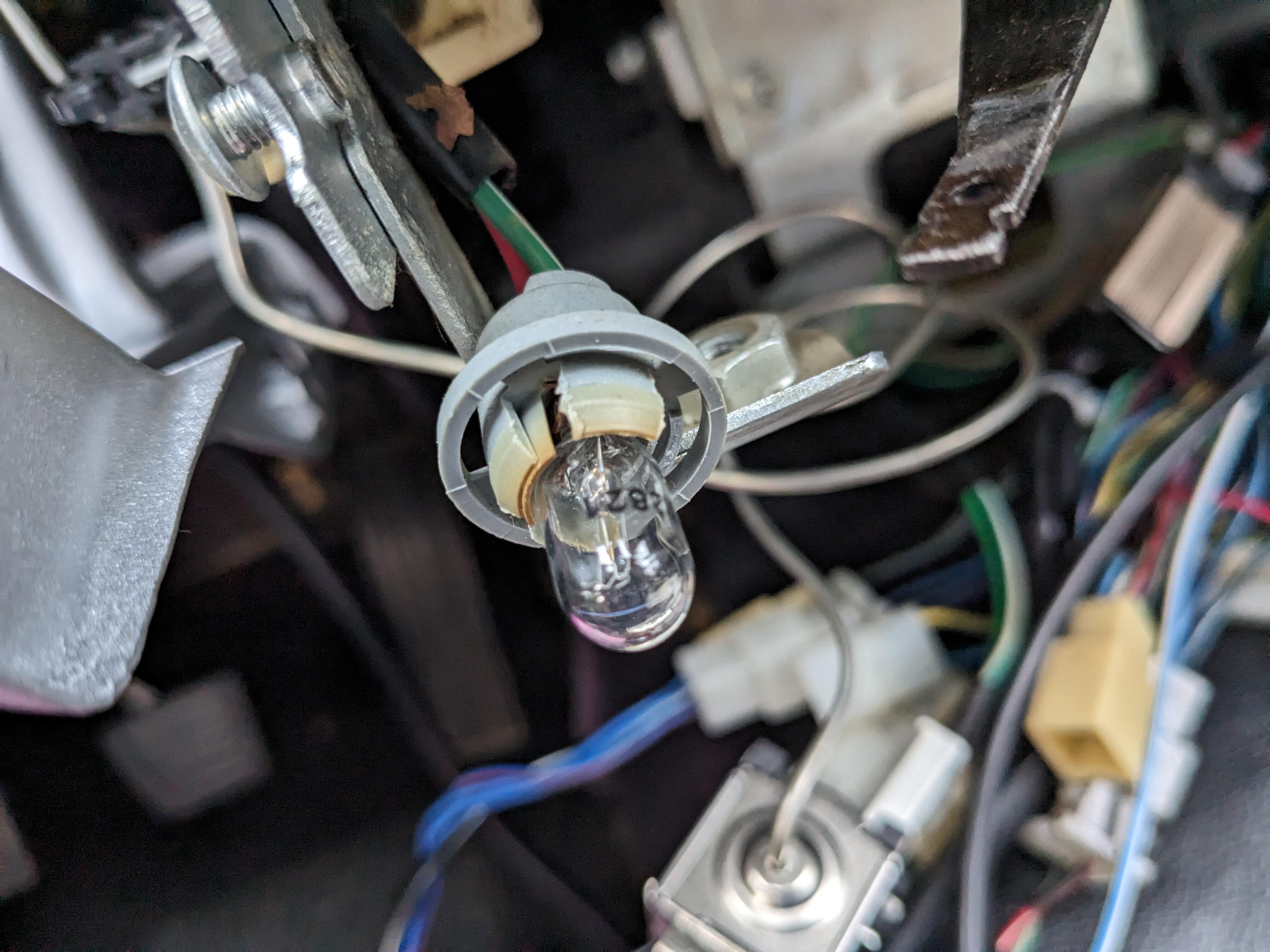
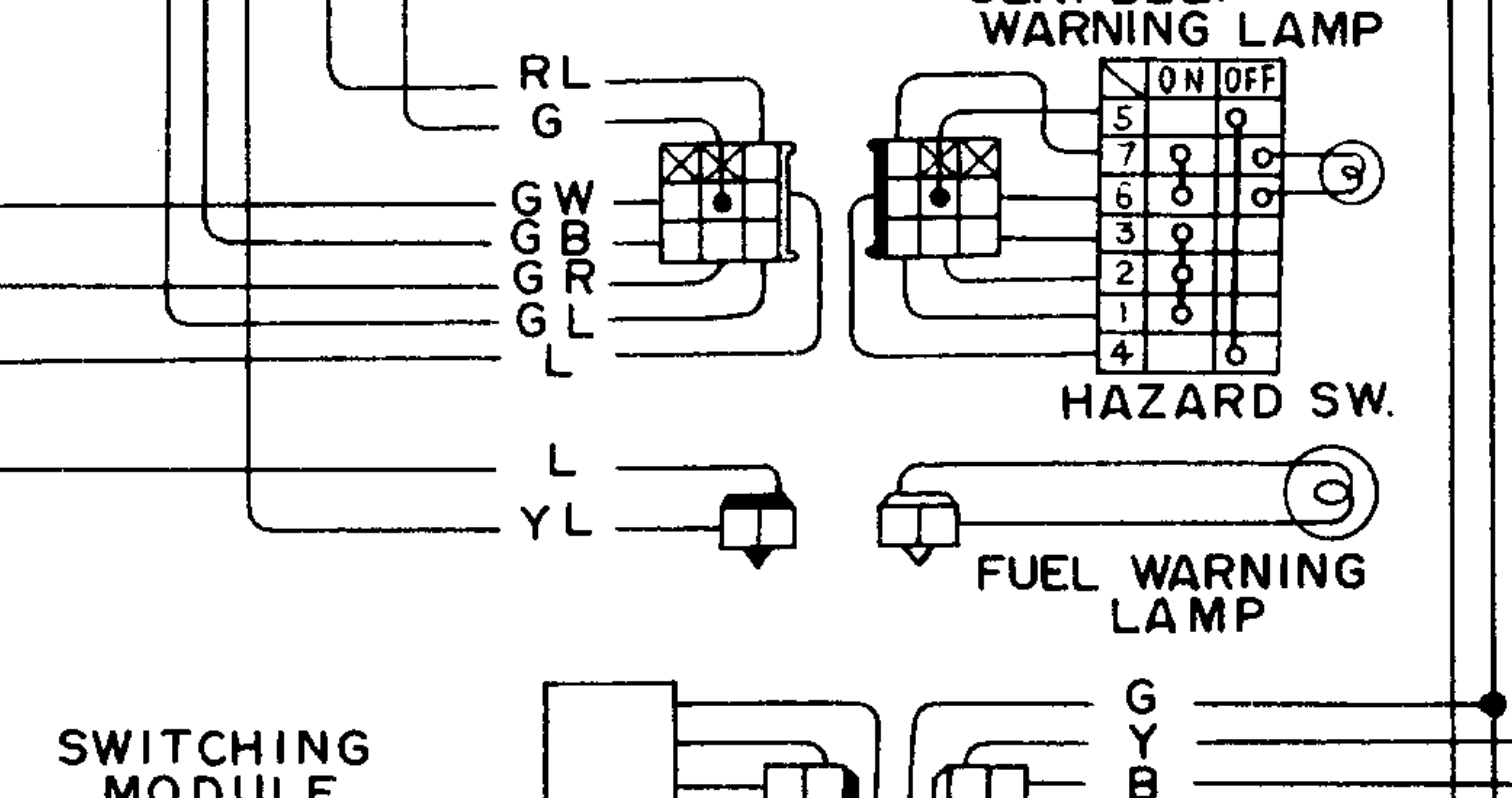
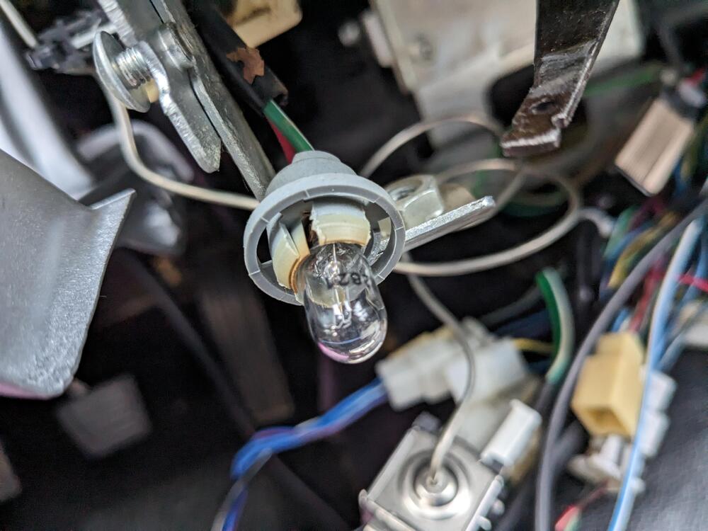
I have at least one socket with broken/dried out tabs for the HVC control panel - I'm not finding anything searching for repalcement sockets in general - has anyone found a generic / aftermarket bulb holder/ socket that will clip in place, that also has the correct bulb depth? I know the bulb socket for the low fuel light will fit here - so I will likely cut the harness on that & use it here. I'd still like to know if there are any useable options for the instrumentation.
-
Yes - mine has the wiring harness in place - CaptO pointed it out when I posted this pic 😊
-
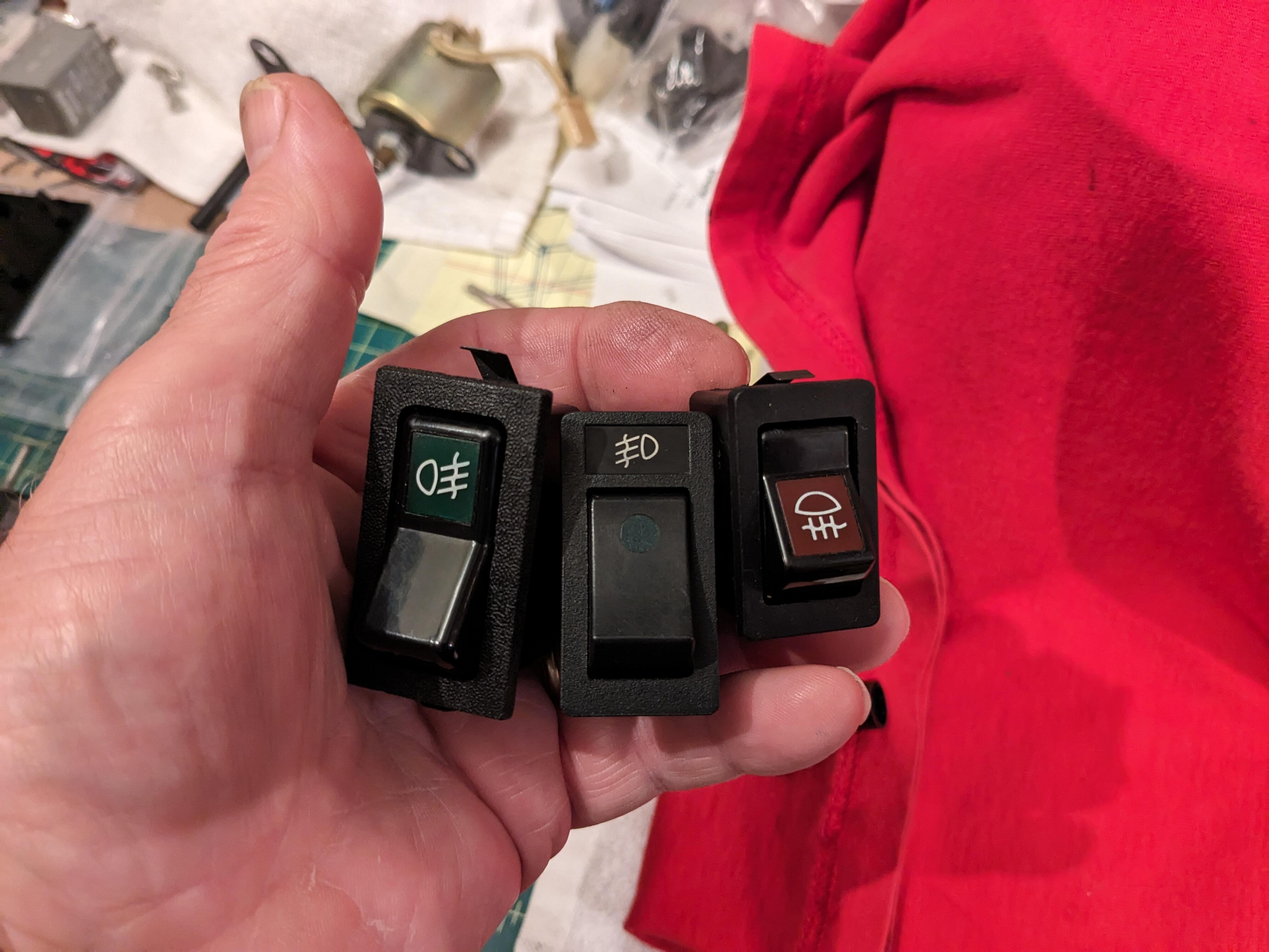
Found some old Volvo fog lamp switches - I think I'll add one & then I can just put some fog/driving lamps behind the lower grille..

-
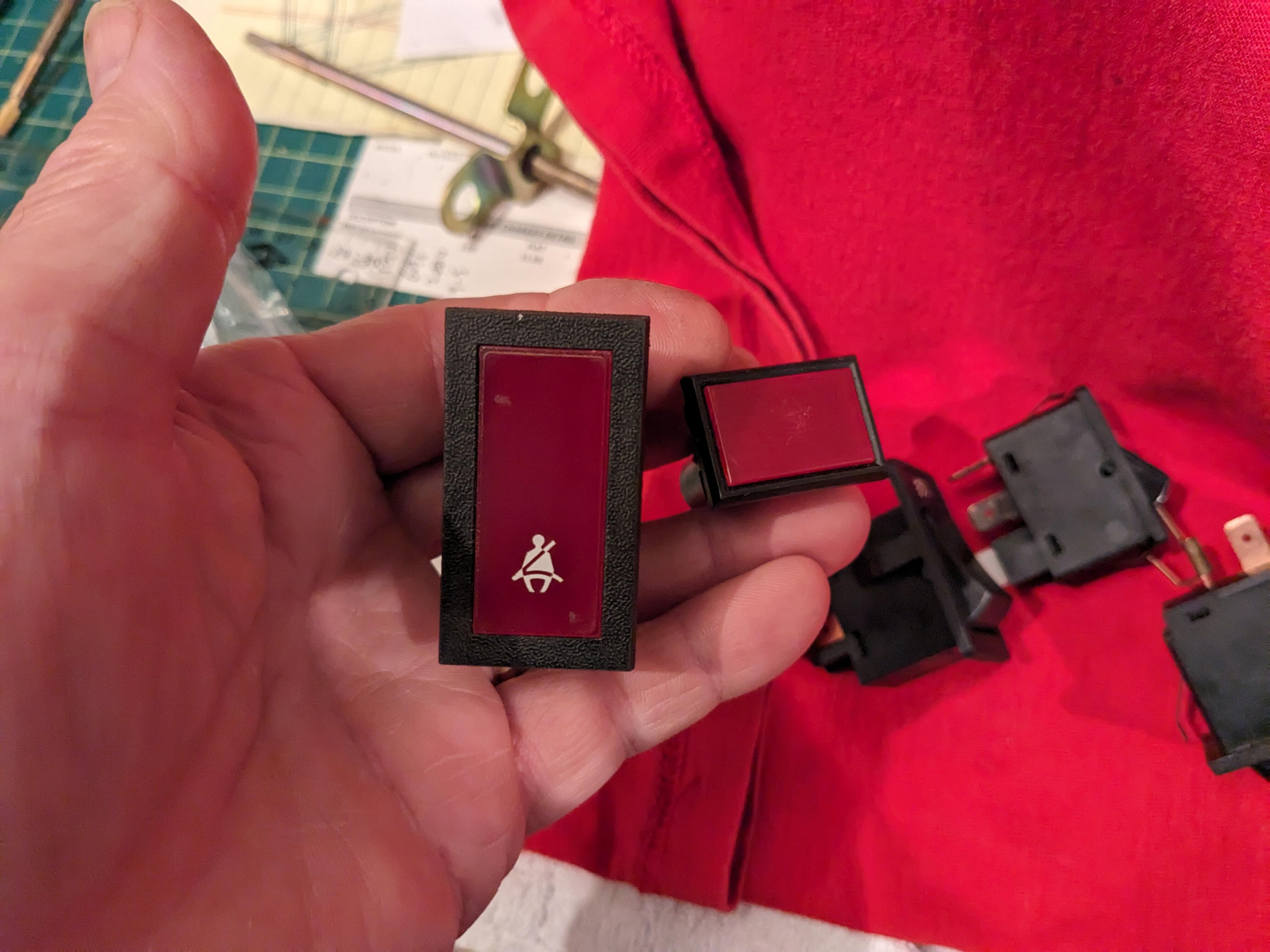
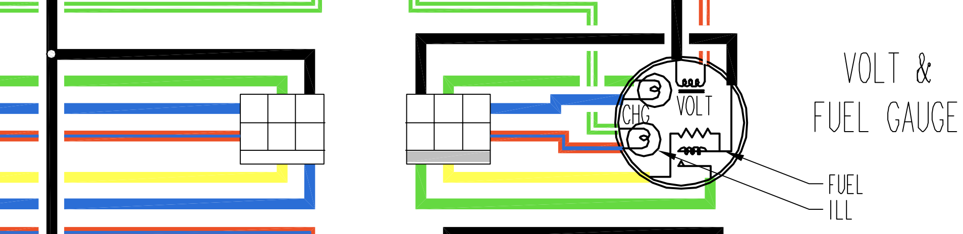
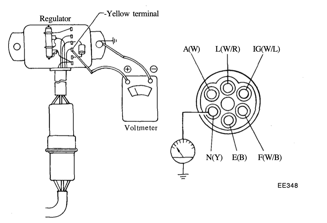
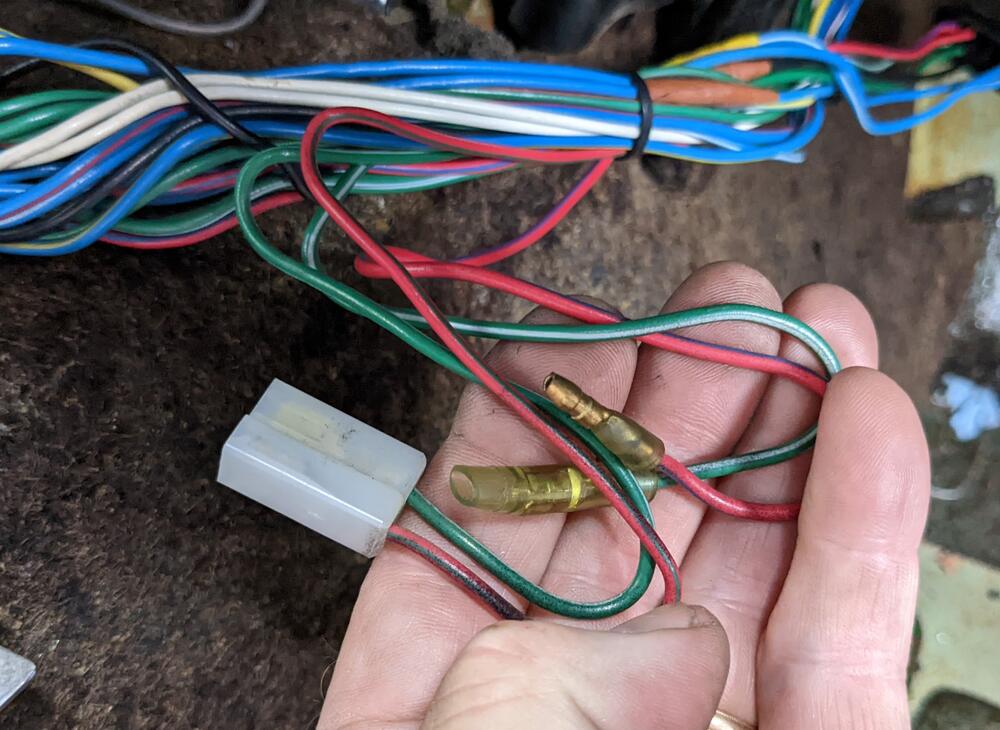
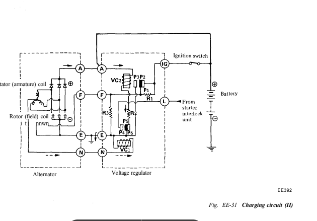
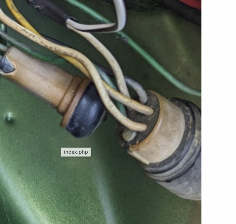
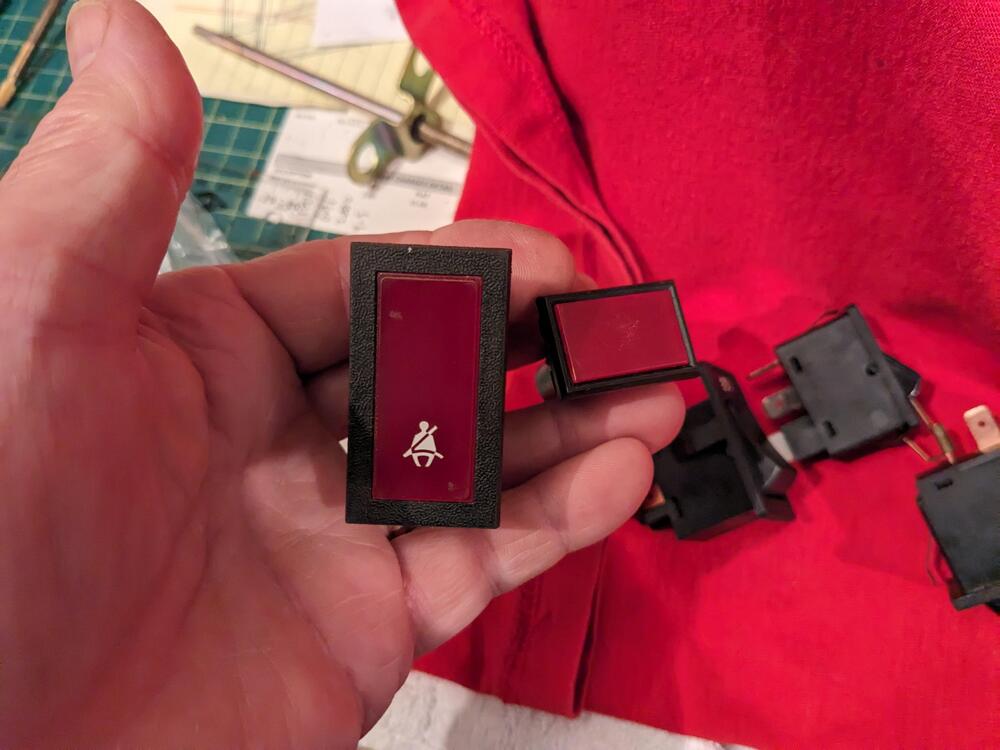
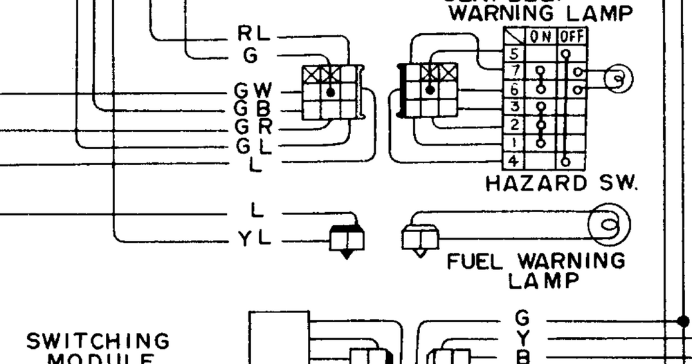
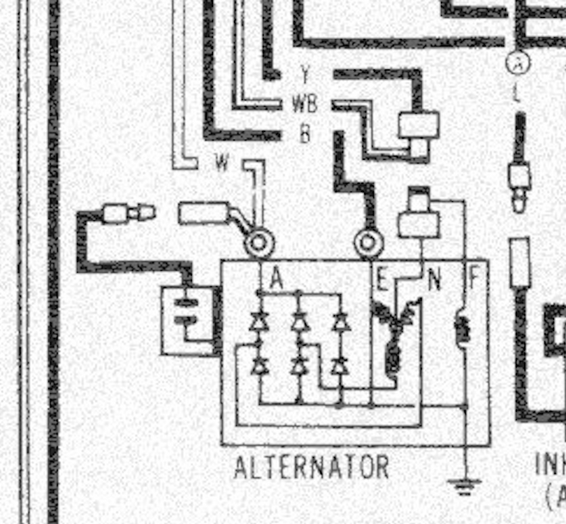
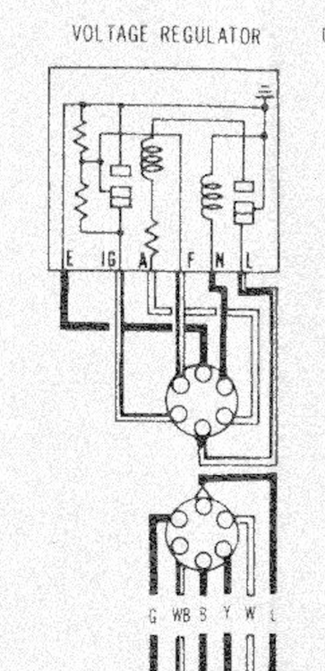
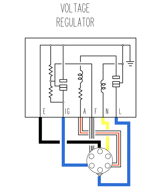
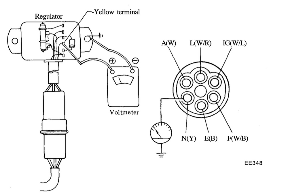
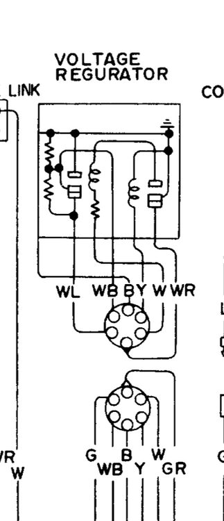
Thanks Steve - I have the 75 FSM (original hardcopy). It matches the online copy that I have, besides the glitches from scanning There is no charge lamp on my 4/75 280Z. I do have the ammeter . Manual shows an interlock relay, but I don't have that either. EDIT - when the rain stops, hopefully Sunday - I'll look at the actual harness plug & see if I can wire a test lamp to the L circuit. Should be easy enough to determine from there if it will suit my needs. Thank you for pointing out the L terminal in the other thread. from page EE-14: EDIT -lookng through my earlier pics - I have an empty spot in the v/reg harness for the L terminal EDIT - thinking about the actual lamp - I can repurpose the non-functional low fuel indicator. I'll cut the Bl/Y wire back in the harness & connect that to the L terminal & Blk/Wh wire at my AC relay. I've taken a Volvo seat belt warning lamp & sanded off the symbol, so I can fit that in the console for the charge indicator lamp
-
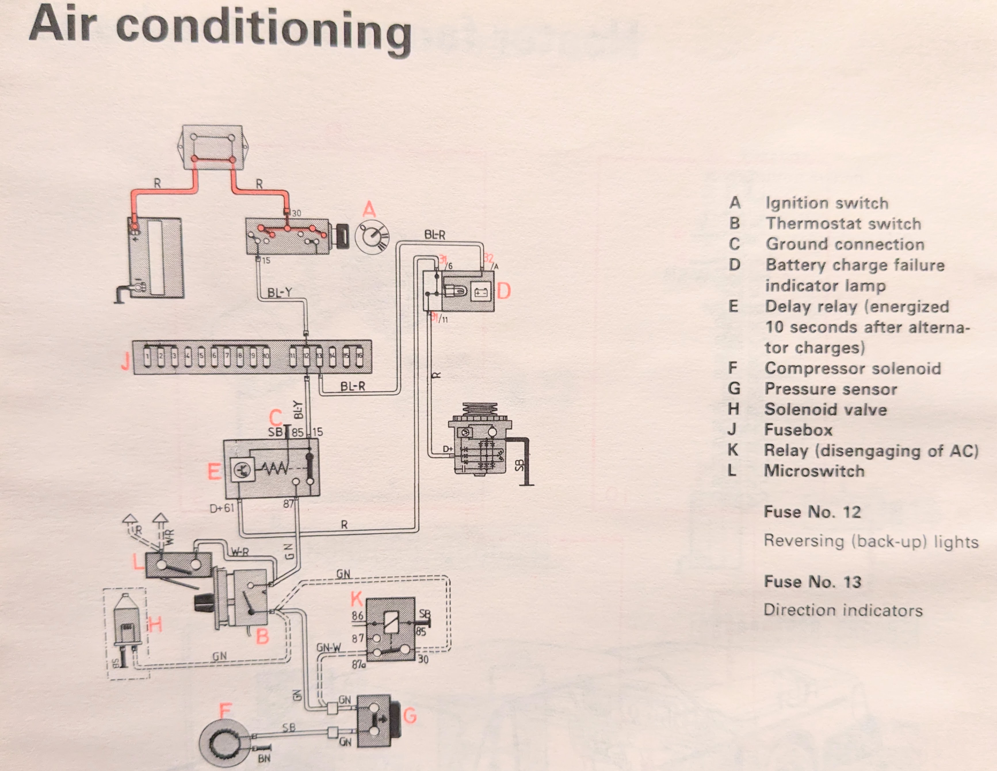
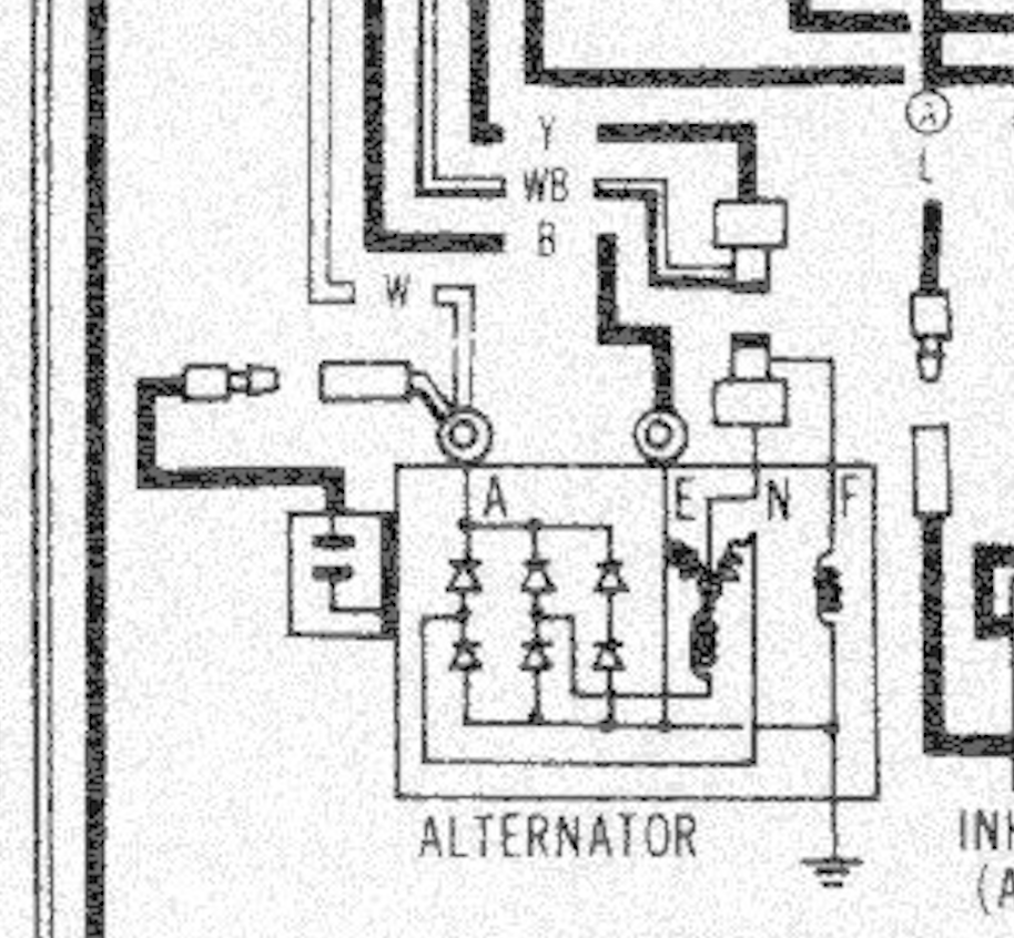
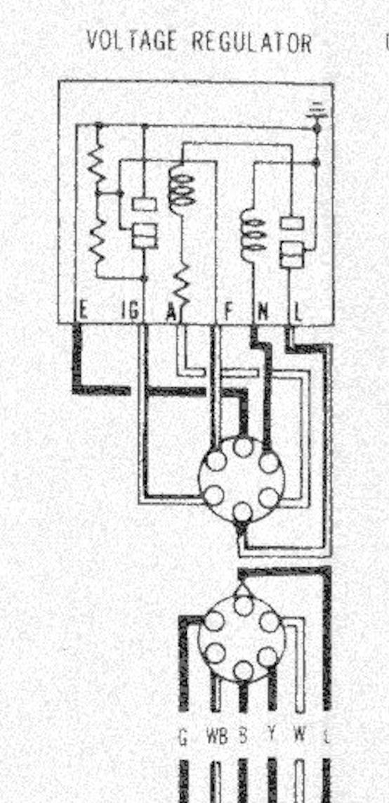
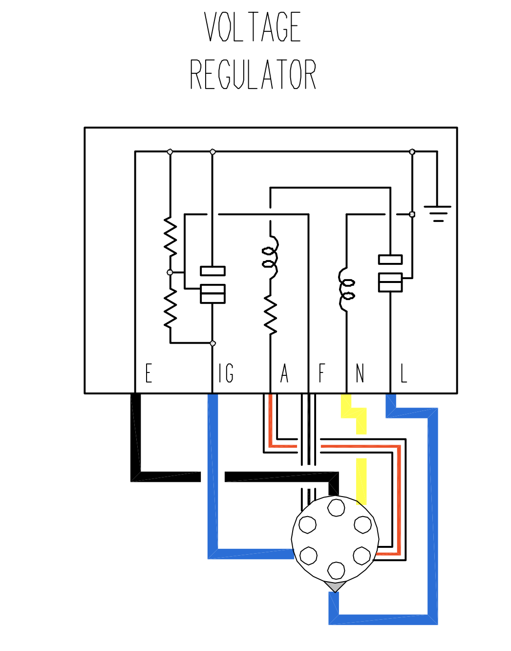
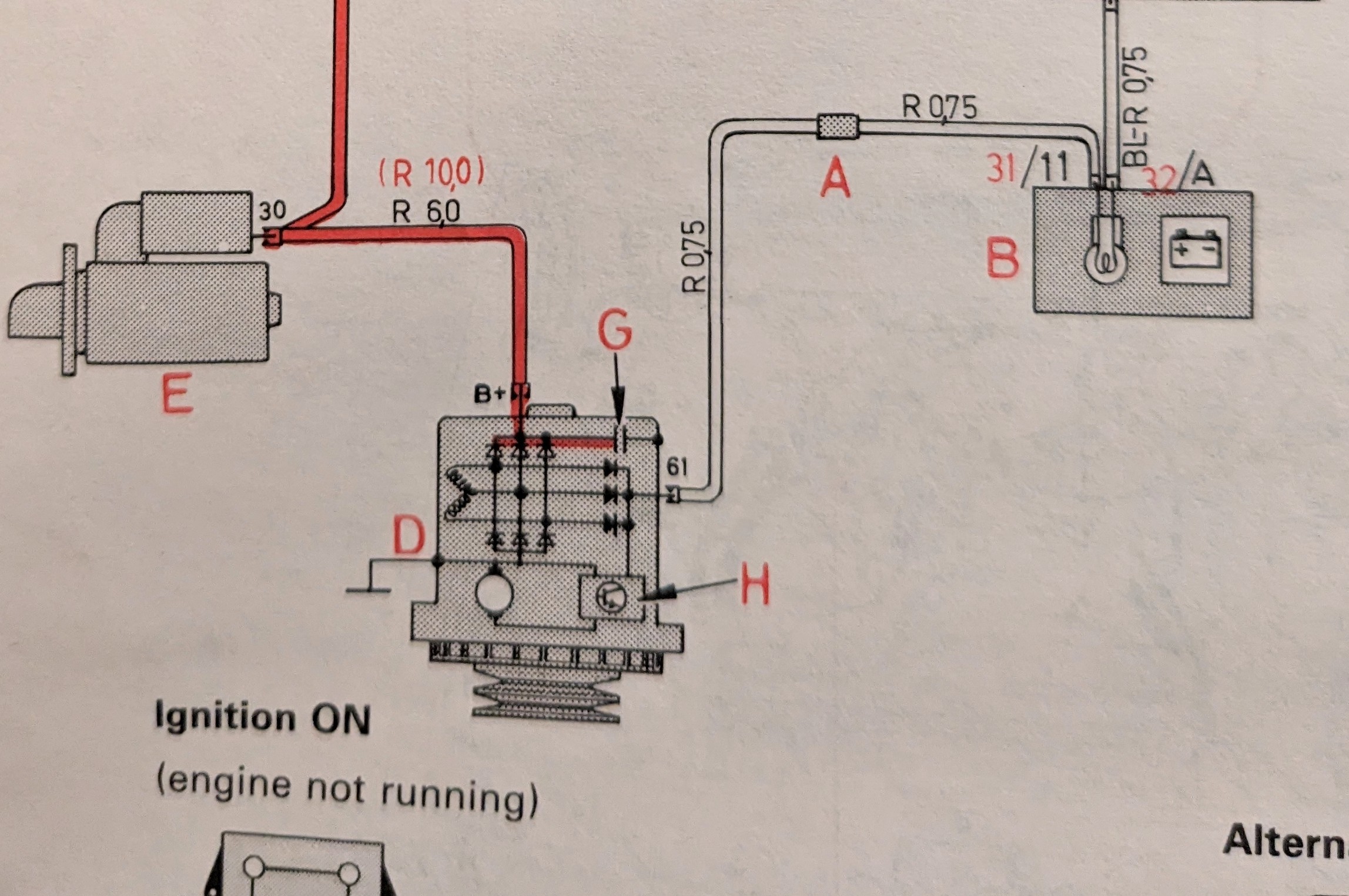
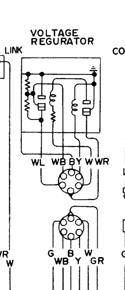
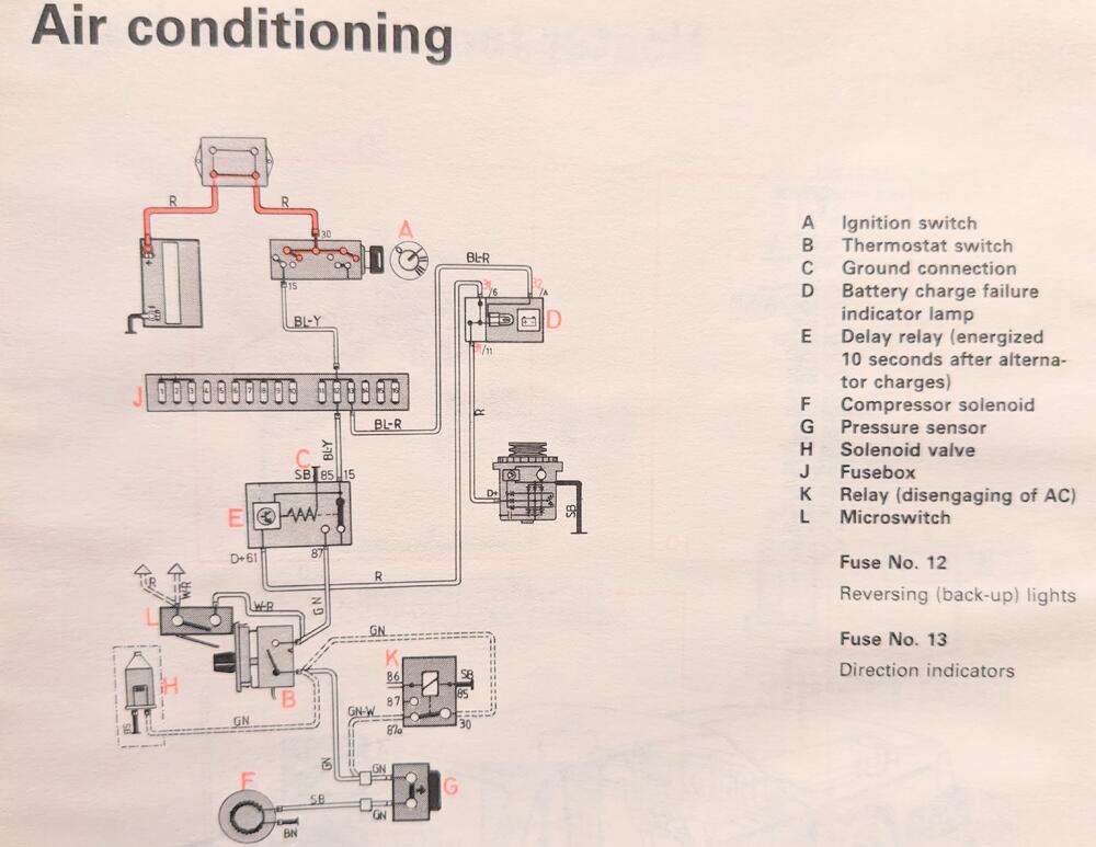
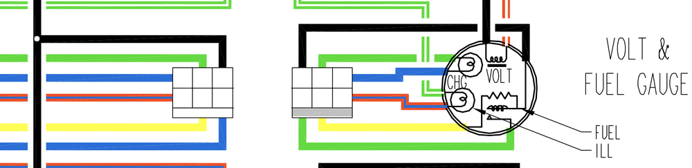
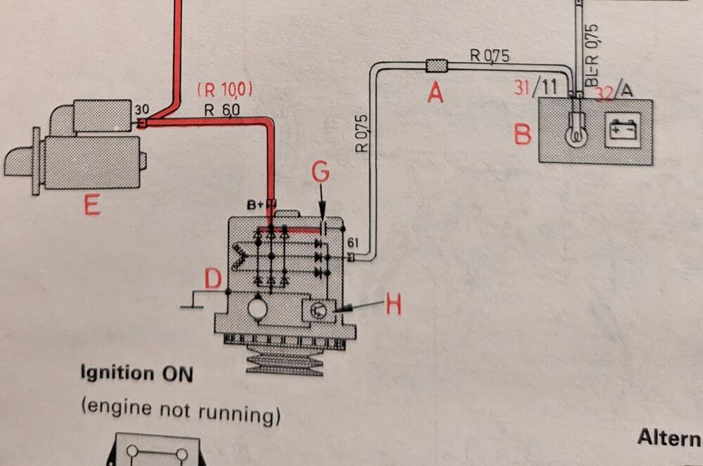
So, a little background. For my AC system control relay, I need a signal that ties into the charging circuit (D+61). On a Volvo, this would travel to the ground side of the idiot light, and ground through the alternator (D+61 terminal) when the engine is not running. As far as I can tell, there is no way to wire this to the alternator, as it doesn't have a equivalent connection 75 280Z Volvo alternator, has an additional diode pack. I don't even know if using a later internally regulated Datsun alternator would fit the bill. I read in another thread (can't quote it here) @SteveJ - That the L terminal of the V reg would serve to provide the charge indicator lamp circuit I need The 1975 wiring diagram shows a wire connected to the L terminal, but it also shows a voltmeter, so I'm assuming that is an error 77 color diagram shows the wiring through to the voltmeter & charge indicator lamp 75 diagram - The wiring diagrams I have show a Blue or a Grey connected to the harness side of this. Following it through, it seems to go to the Interlock Relay (which my car doesn't have) FSM shows a W/R wire connected to the L terminal though. So, to get to the point, does the '75 voltage regulator in fact have that L terminal & internal circuit that I could utilize?
-
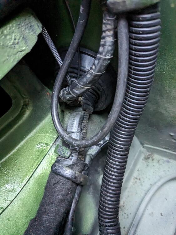
The generic grommet off Amazon will do. Sliced it, then super glued the seam back together. Tie wrap to keep it snug around the harness
-
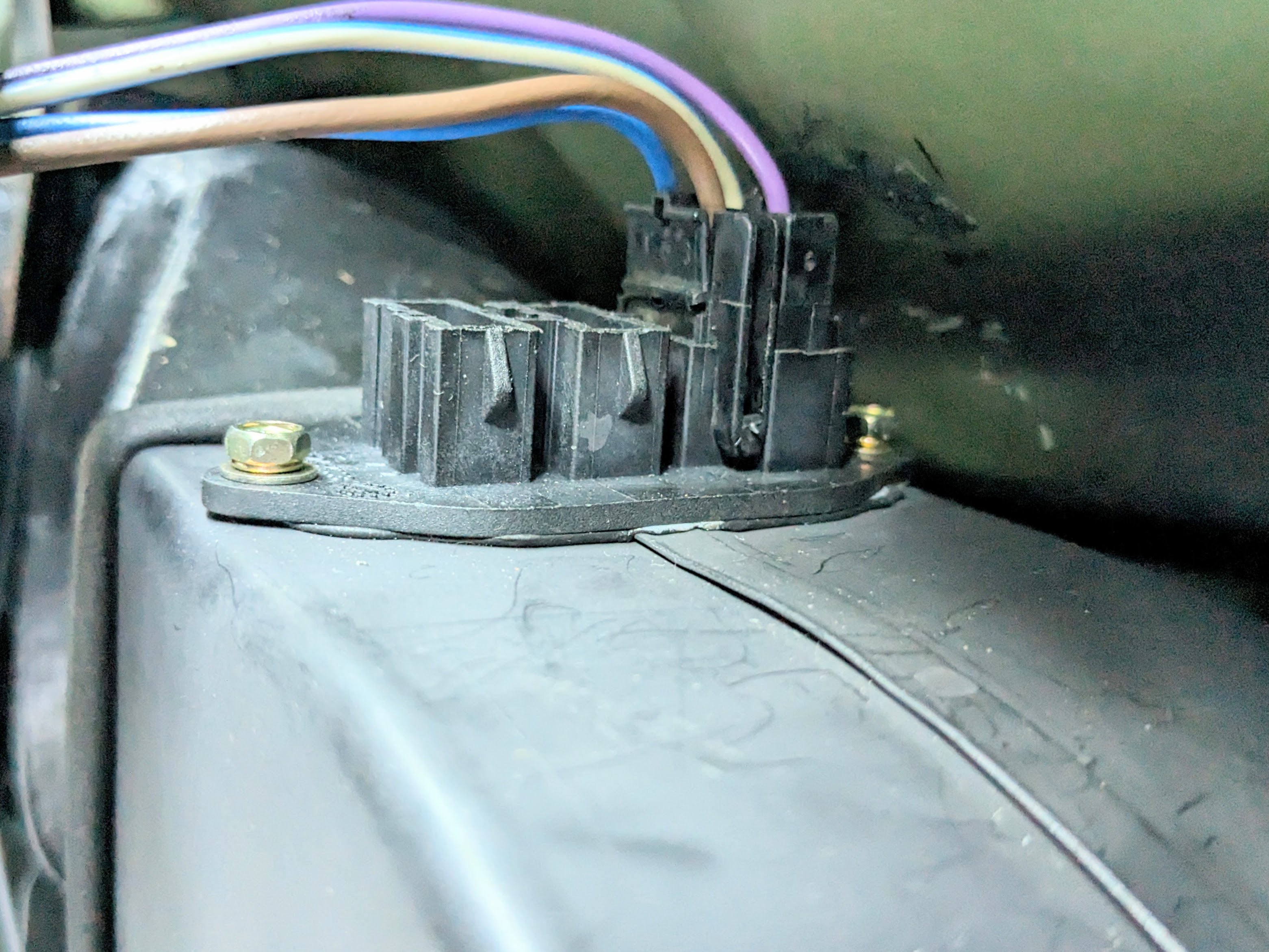
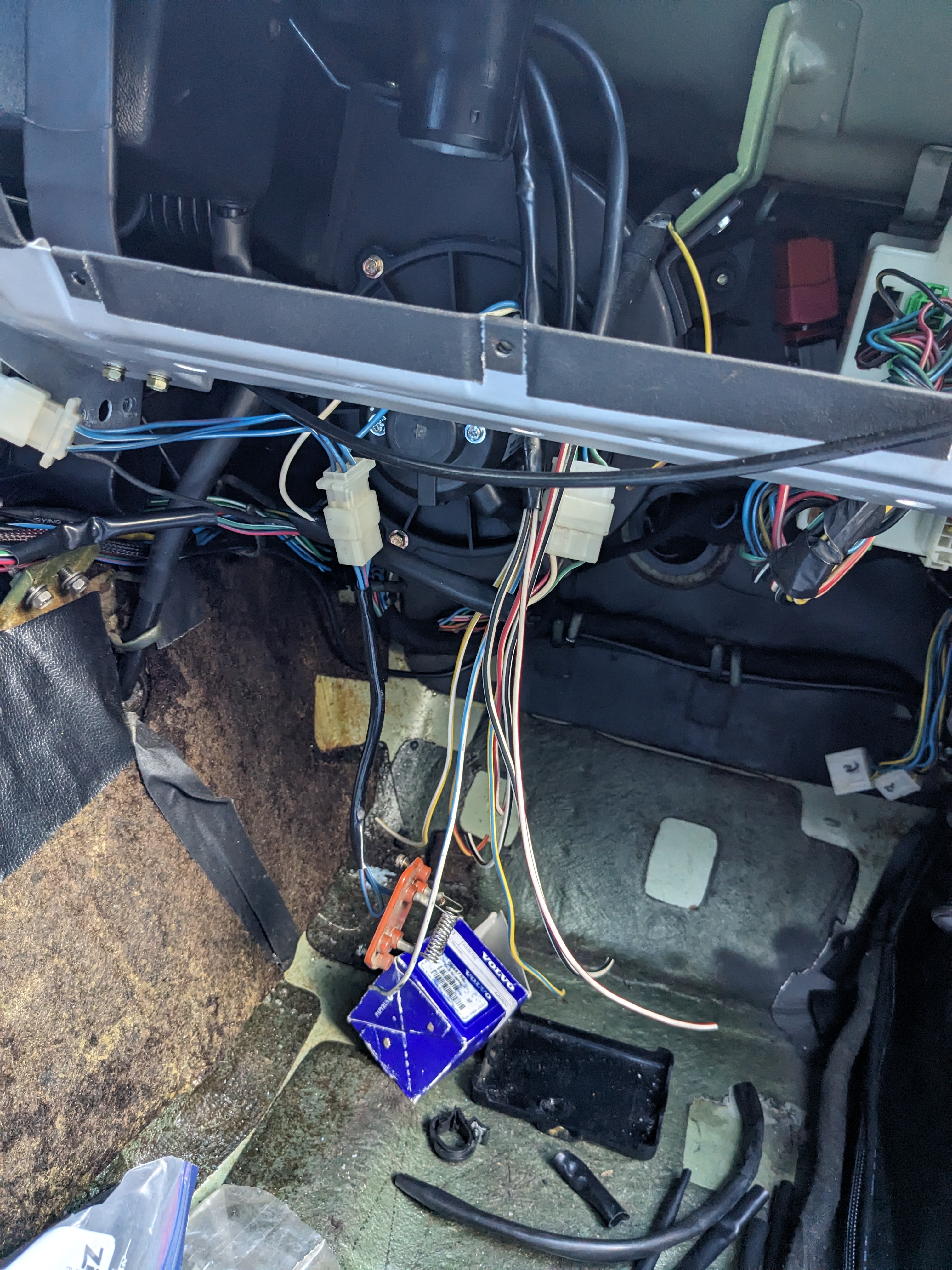
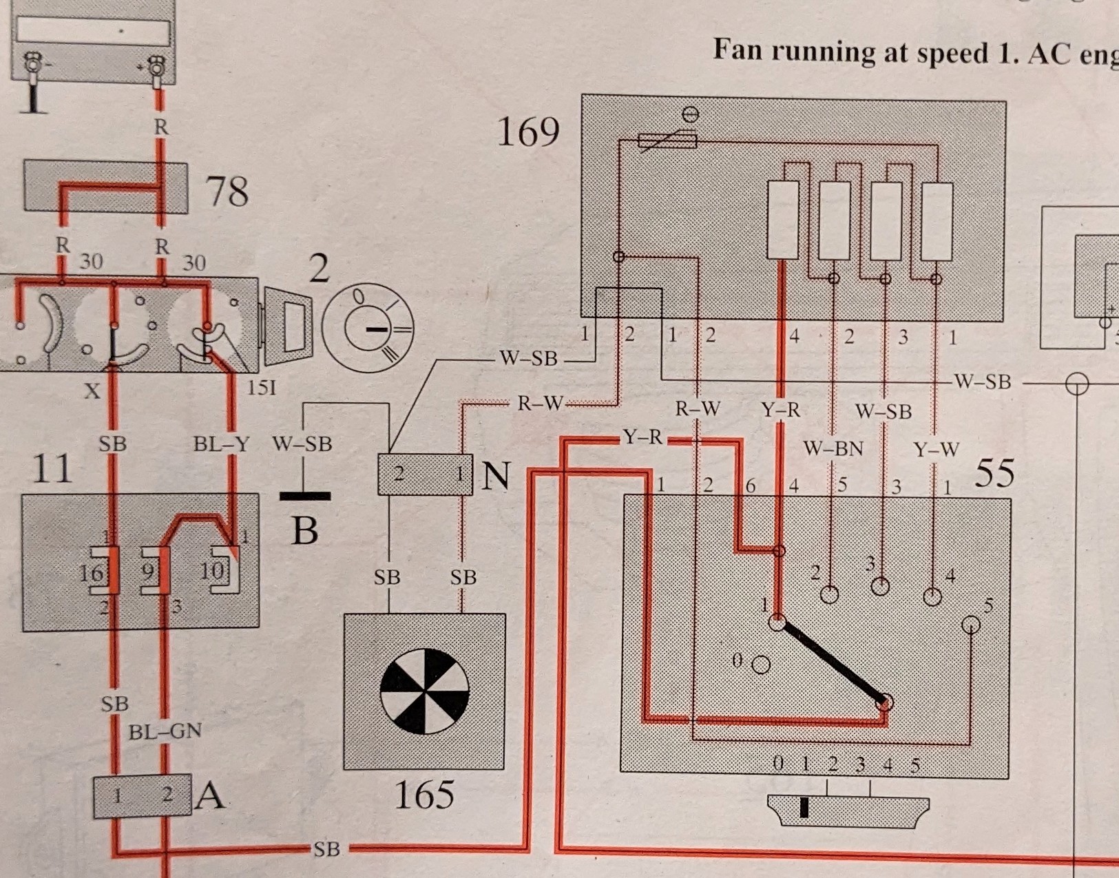
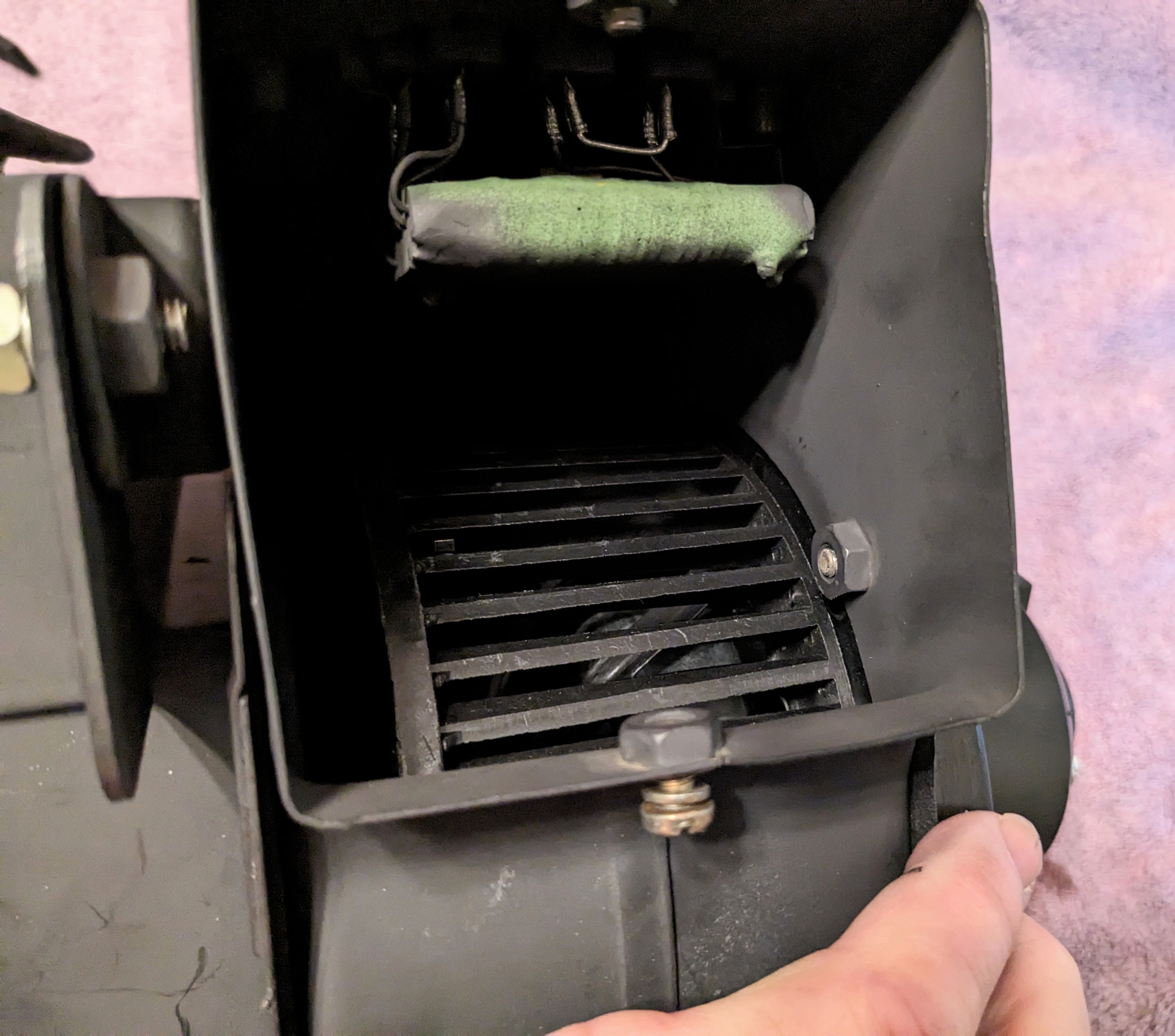
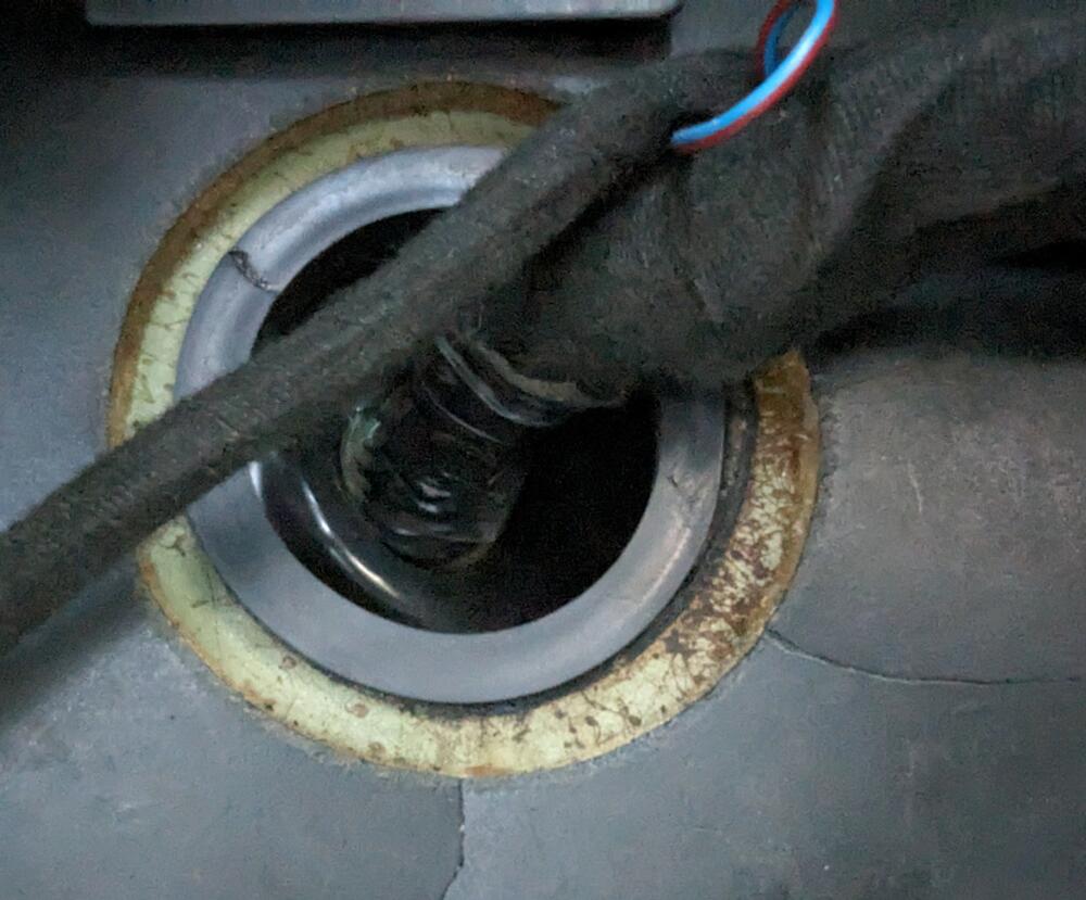
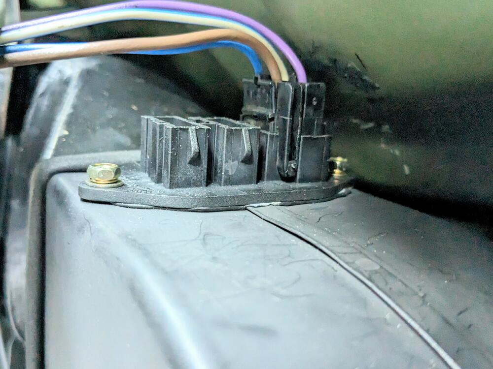
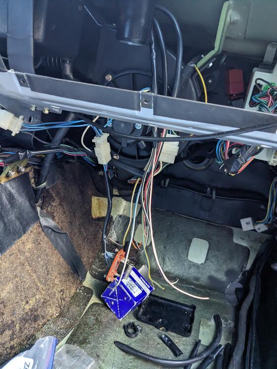
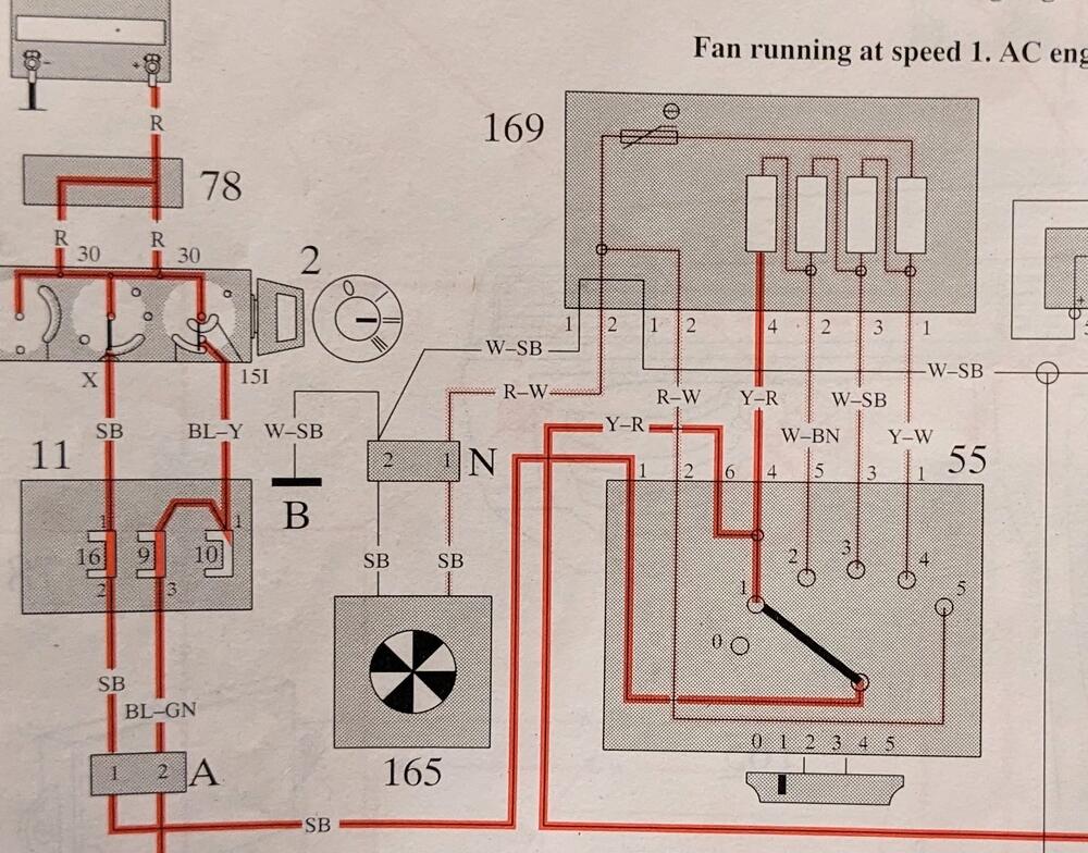
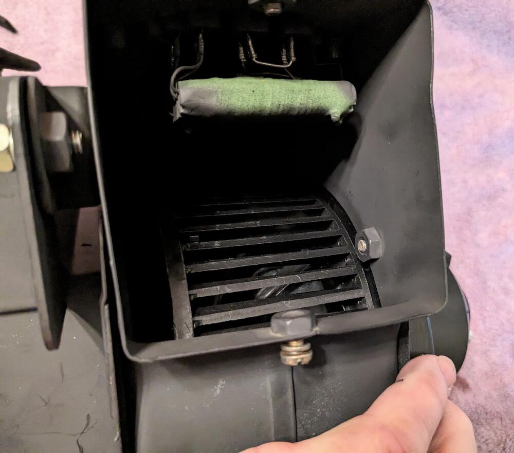
Test fitted the blower/duct casing to check the blower resistor connectors. Had to relieve the cowl a touch to allow the connectors to be inserted/removed. I have a4 speed switch coming, so that will govern 2-5, and 1 will be the AC-on initial speed. (re) wiring the blower resistor - Volvo uses switched (+) to the resistor vs. Datsun's switch (-), so I'm going to change it around - primarily because I've already wired the AC-on feed as a positive input
-
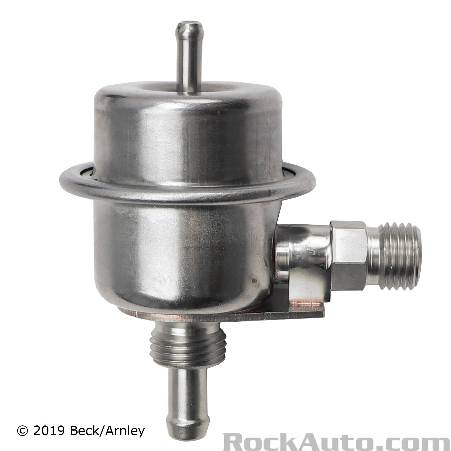
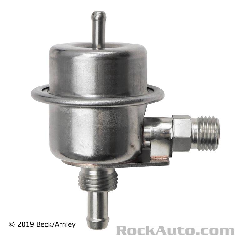
Volvo also used a 2.5bar reg on several models (1983 240 2.3l - about $50 on Rockauto)- one version has a barb return line, but uses a flare fitting for the feed. I don't know what Datsun did on the later 280's. Is it identical to the beetle version?
-
The pickup is in the floor of the tank, correct? How does that work if the fuel level is below the collar? Are there holes in it that we can't see? Curious regarding the design here.
-
There's no way you will successfully braze an aluminum tube in an AC condenser. The age of the material and the thickness will just create additional holes. Just buy a new condenser.
-
I see - I figured 20% was kind extreme, I assumed under 5% deviation would be more appropriate. Anyhow, I returned the set of caps, since all the ones I checked were more like 20% off listed value. If were to buy more, I would look for name brand, not even bother with generic.
-
Will do! Thanks again for all the help!
-
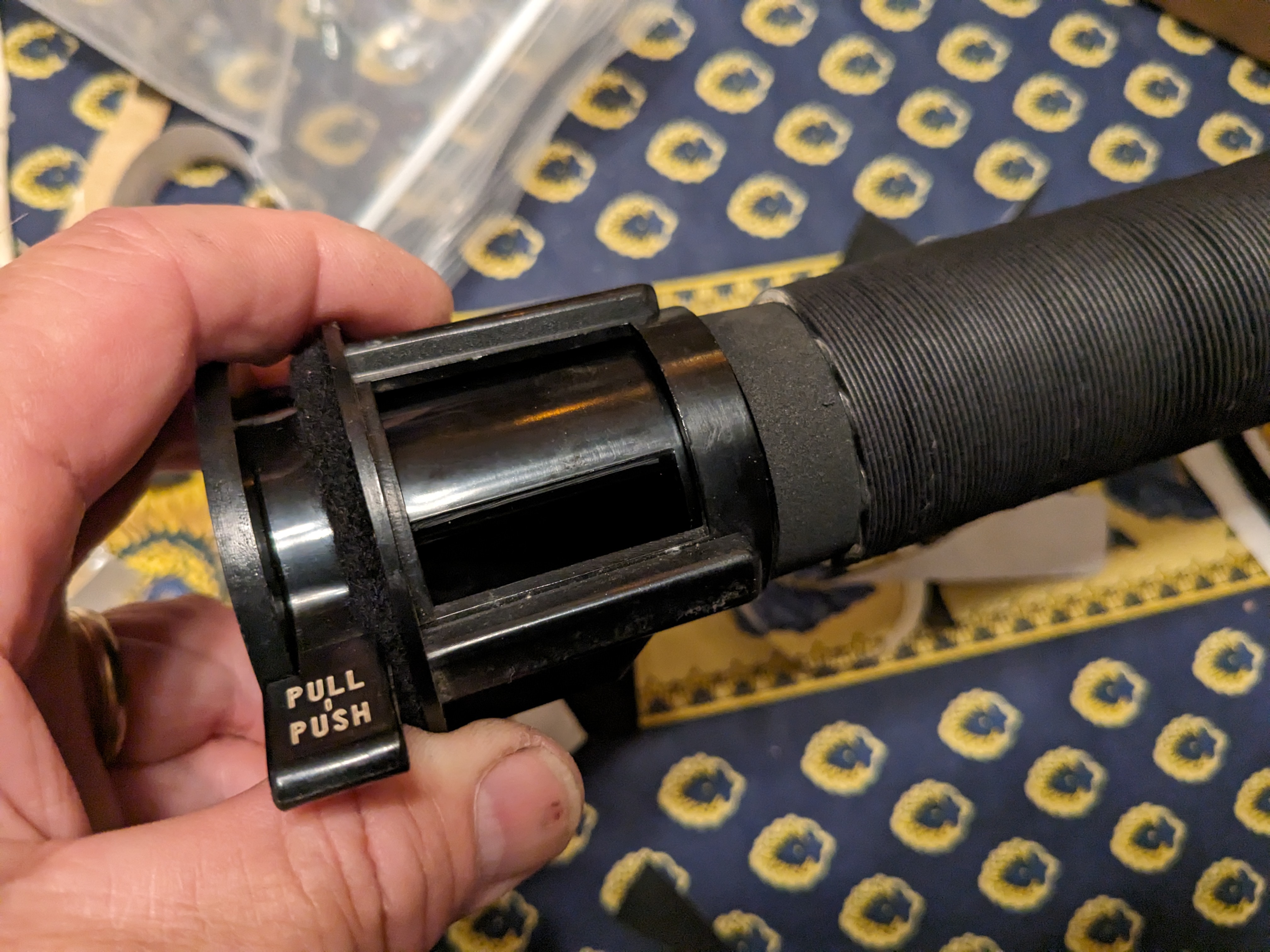
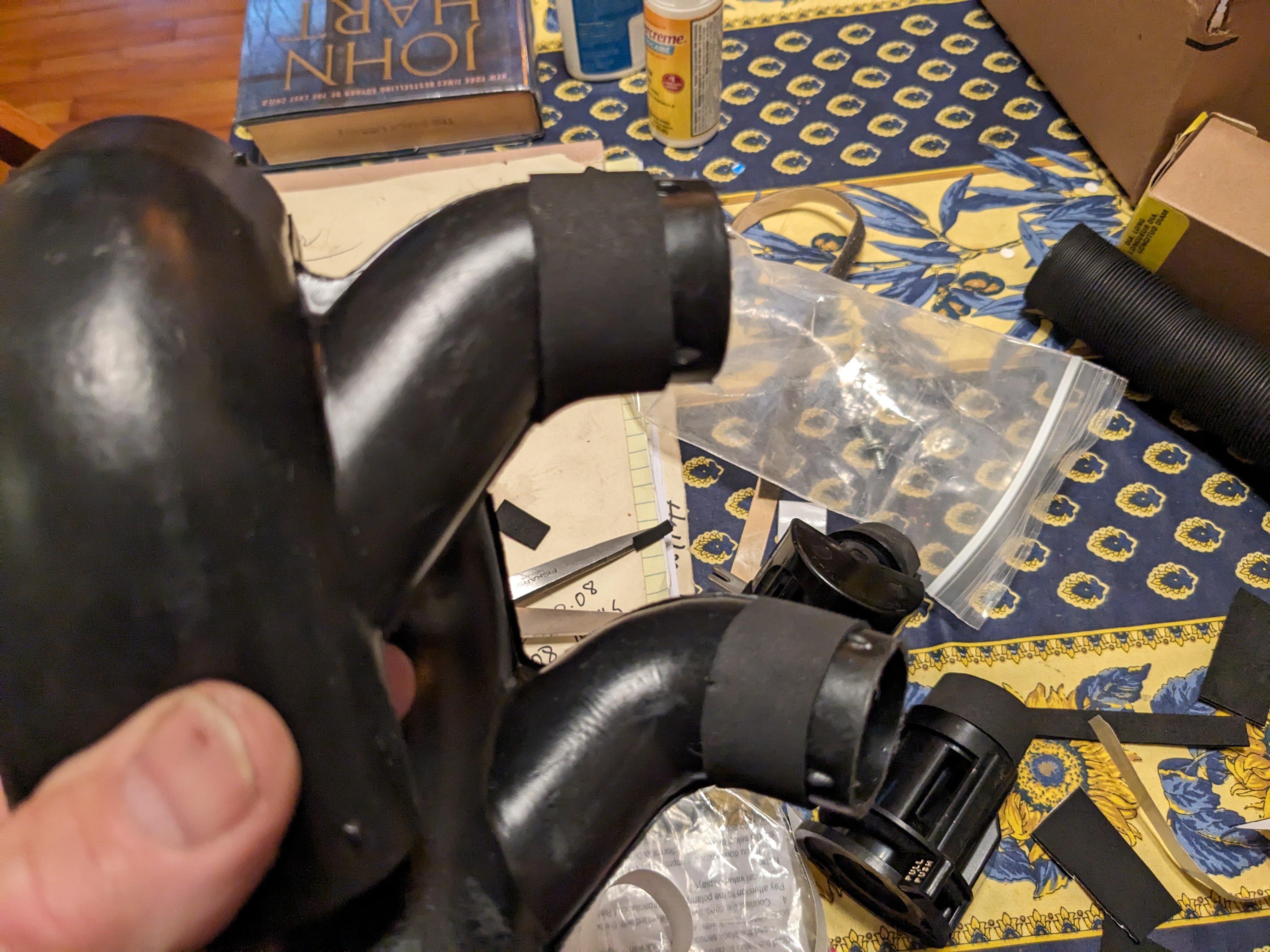
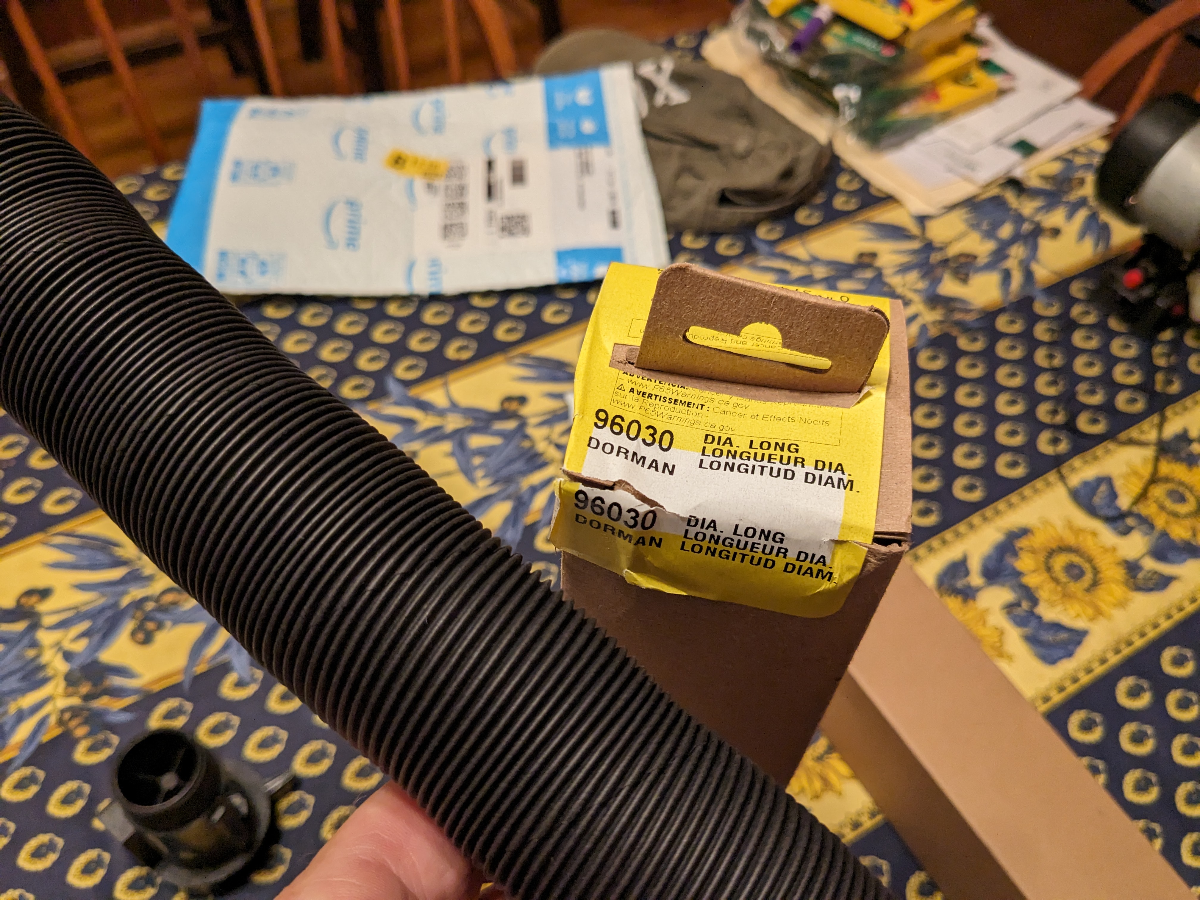
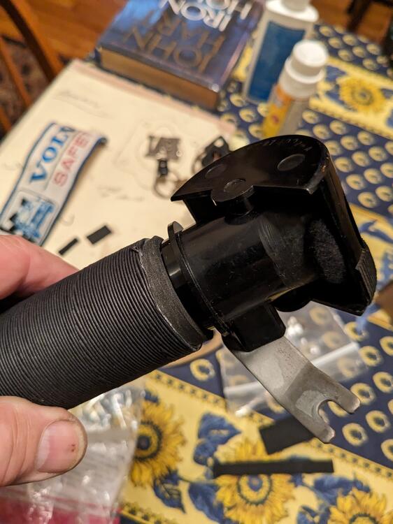
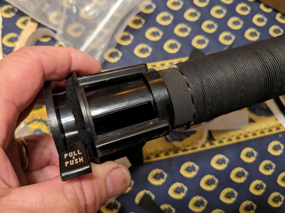
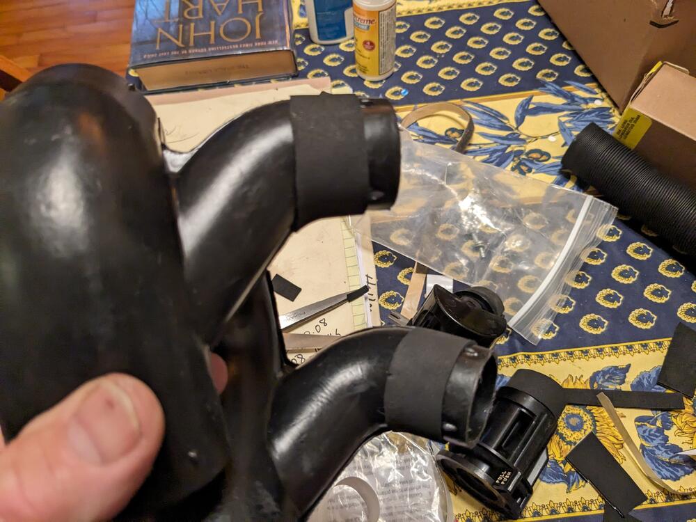
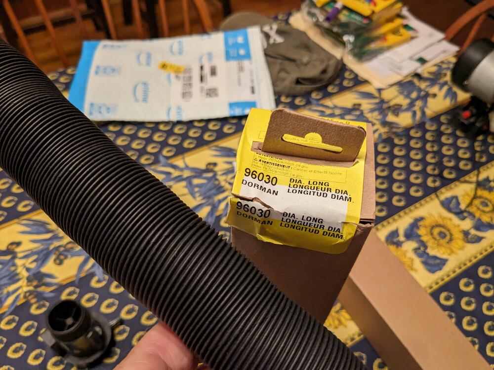
Dorman 96030 works. Had to add a thin layer of foam to make it snug - 1/8" on DS vent, 1/16" on other 3 fittings
-
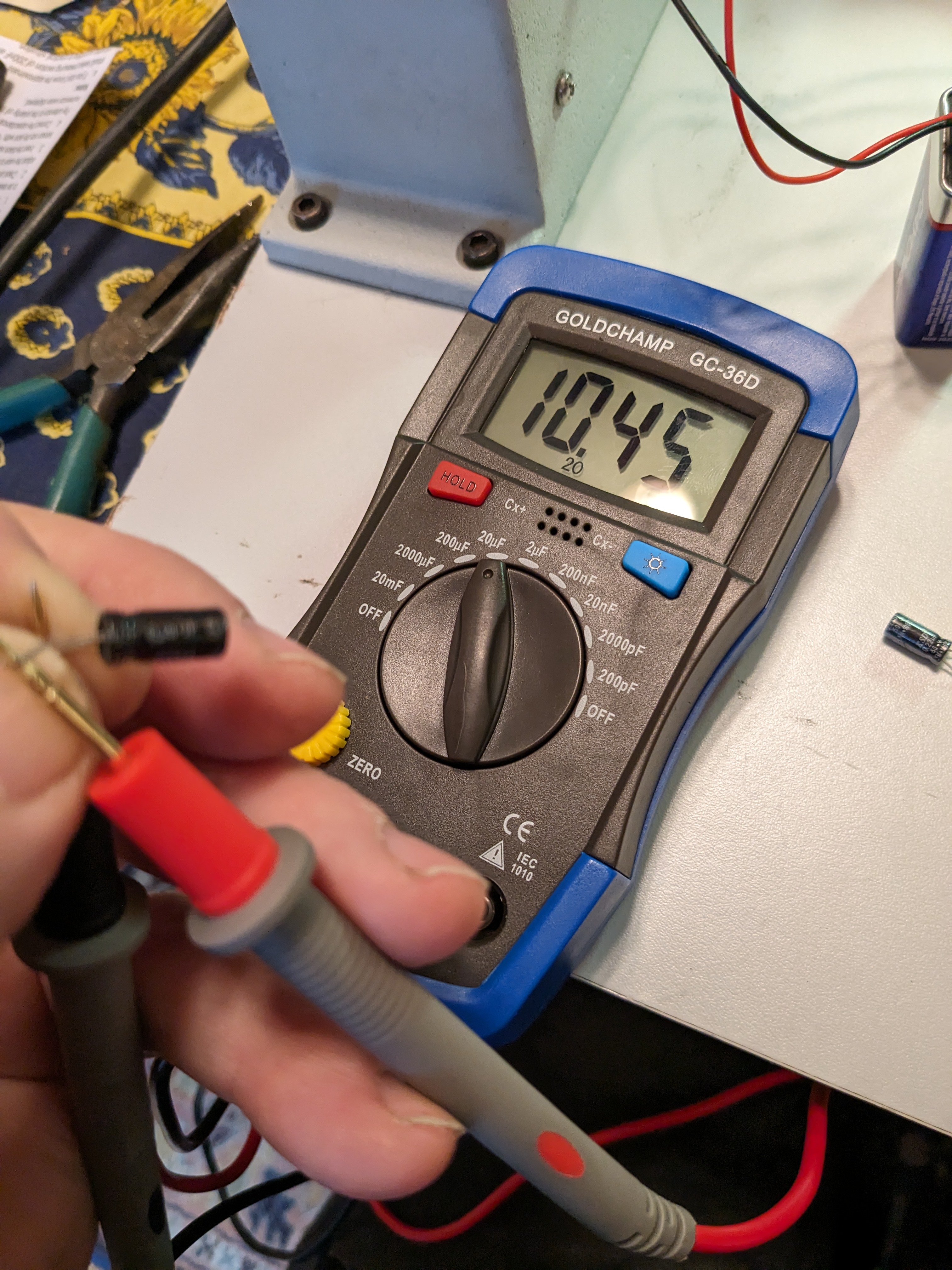
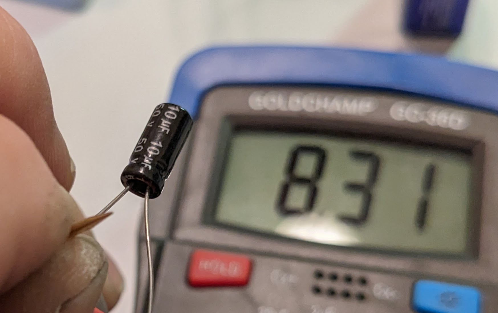
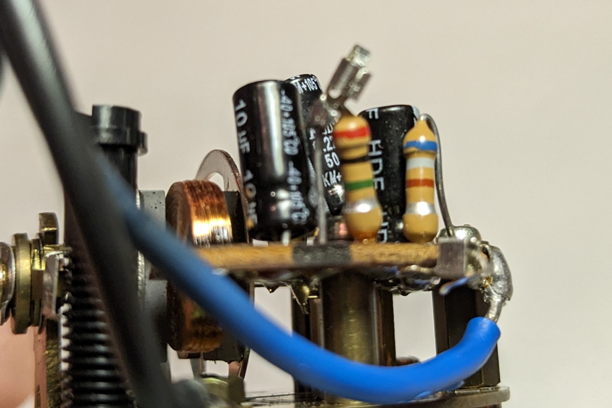
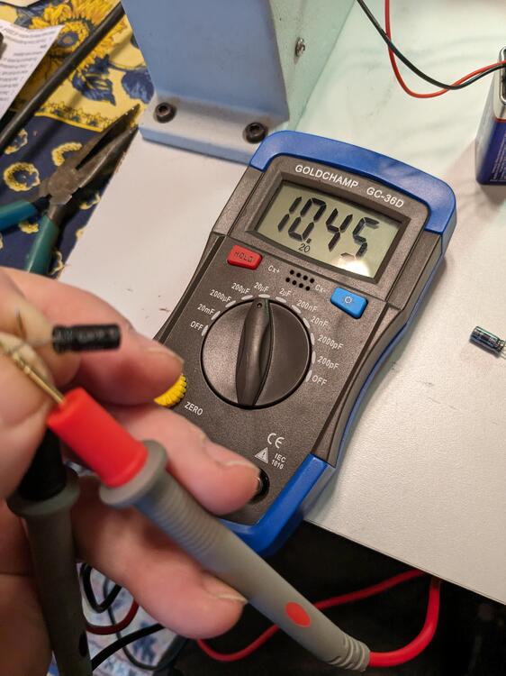
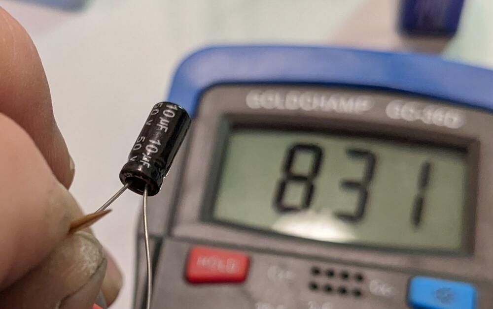
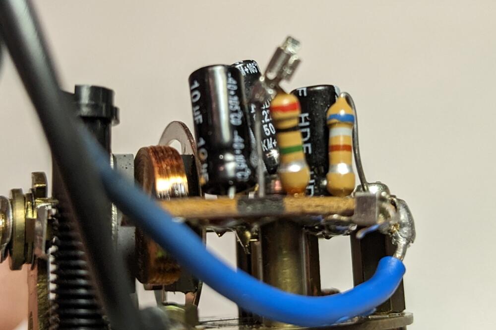
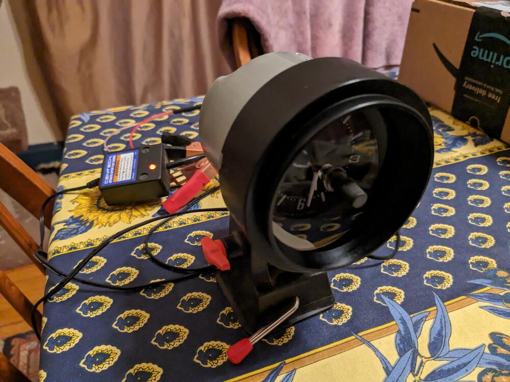
Been raining all weekend. Since I can't work outside, I got back on the clock repair. First, I checked some of the remaining caps rated at 10uf. Most of them were 8-8.3uf (!) , others were 10.5 or higher. The .22uf caps were all under 2.1, most were .2 or below. I removed the .22uf (read as .20) and one of the 10uf (read at 10.45) from the circuit board. The other 10uf read at 10.3, which was closer than most. I found one .215uf and one 10.1uf cap, so I installed them.I also added 2 sockets (not in focus, sorry) to allow me to plug in various resistors if needed to adjust the resistance of the 2M resistor Turns out, I didn't need that - with the replaced caps, the wheel was triggered & the clock runs. It's been keeping time since 2pm, so I'm hopeful that's that.
-
So on yours, you use a TPS wired into the stock EFI to set the integral IACV high flow mode off idle? I haven't seen anything like the BCDD on any early EFI Volvo - I'm curious why they went to such elaborate lengths to limit high vacuum on decel - don't they have oil control piston rings that would limit oil and unburnt fuel being sucked past the pistons on decel? I can't imagine it's there for any other reason than for emissions. I don't recall there being an issue with that on the 70's L6 Volvo EFI (D-Jet) motors, or on the Fiats that used the same L-Jet flap meter setup.
-
The main objective is to maintain a stable idle and base rpm, regardless of varying load conditions (AC cycling, etc.,). It provides low flow mode in decel, so that would be like the BCDD in that it prevents excessive manifold vacuum, and then has a high flow mode for any throttle position under acceleration. So, 3 modes.
-
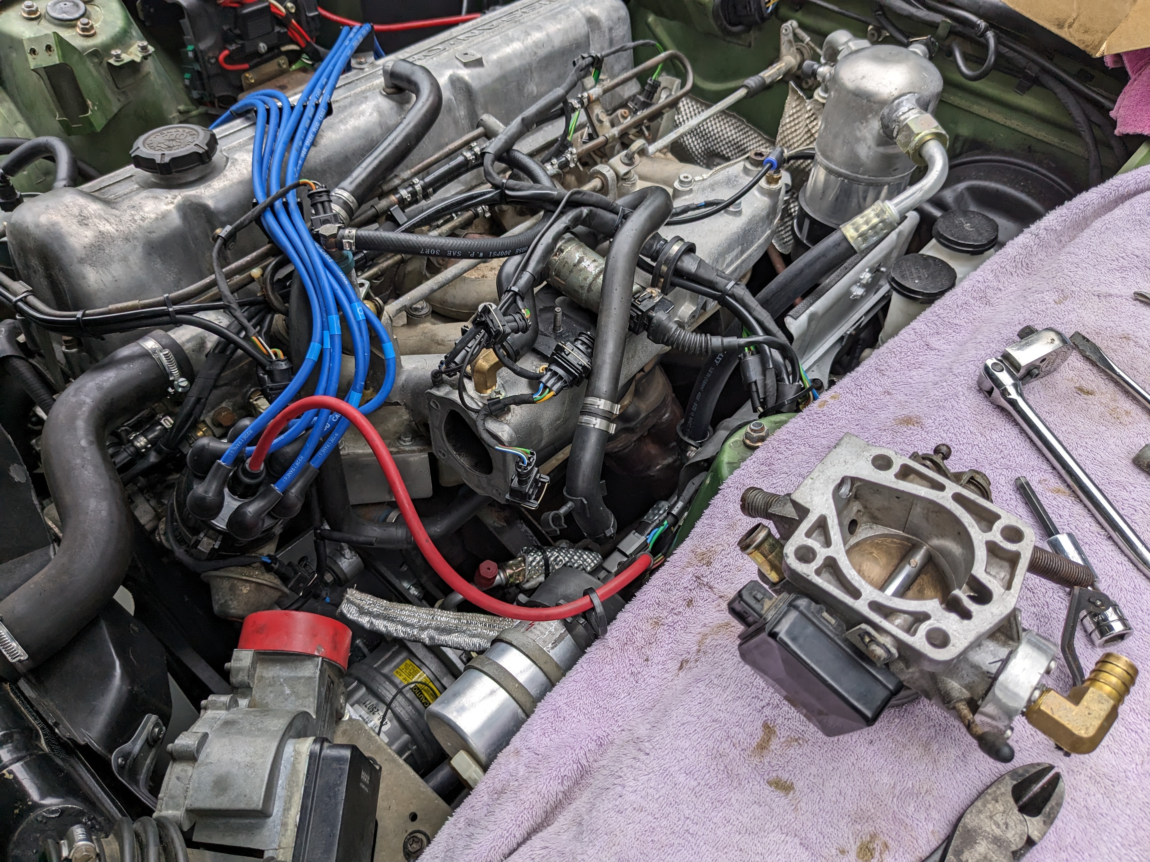
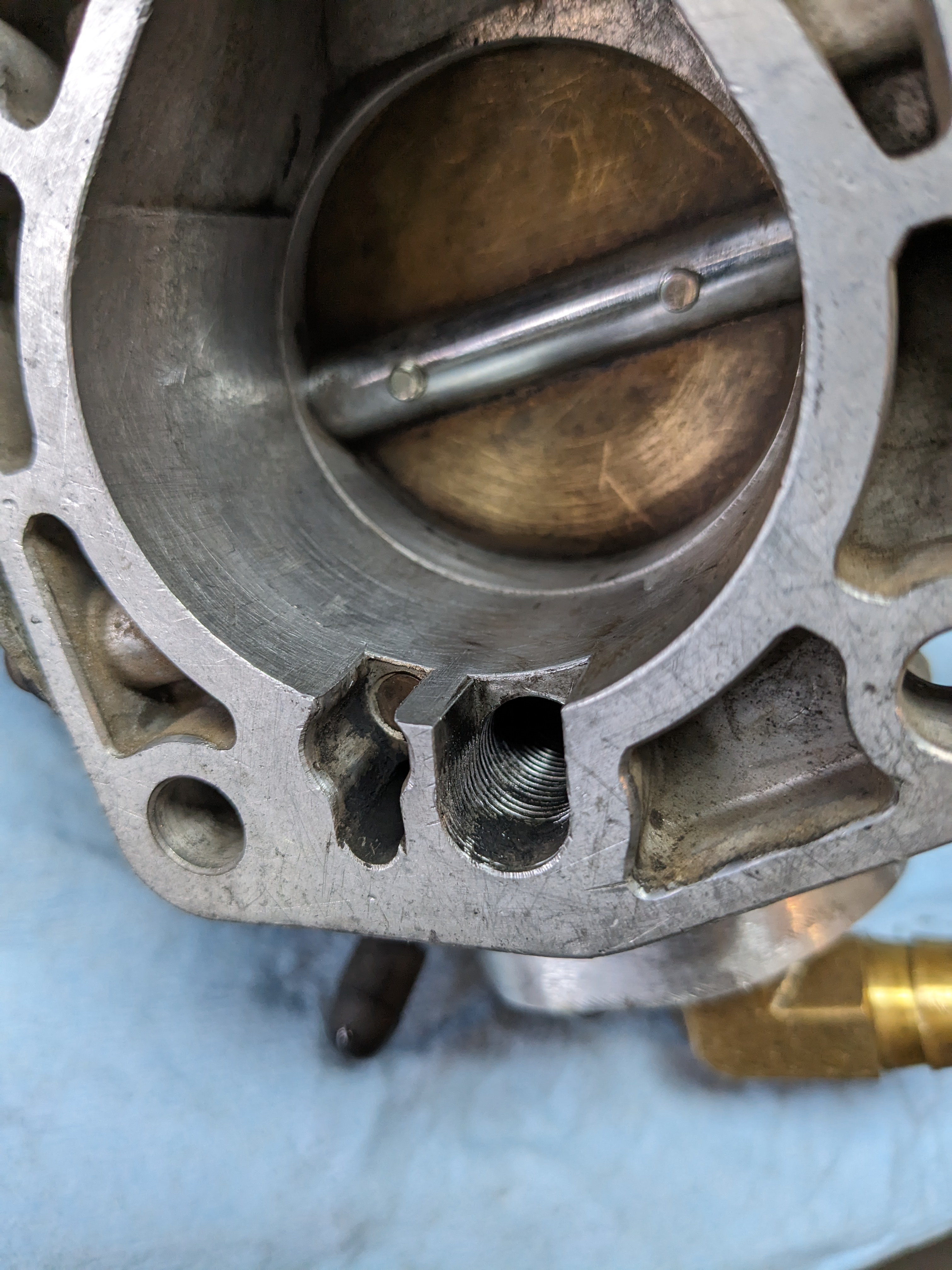
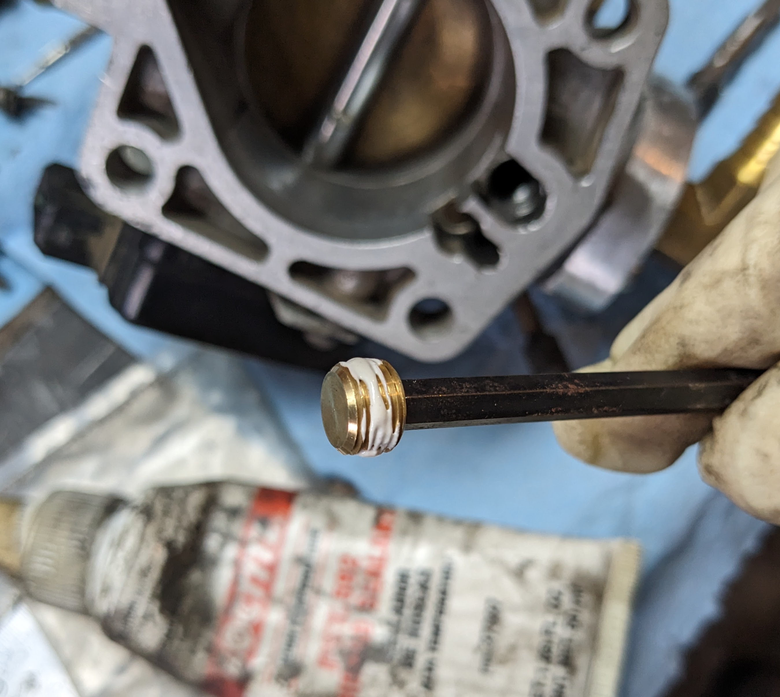
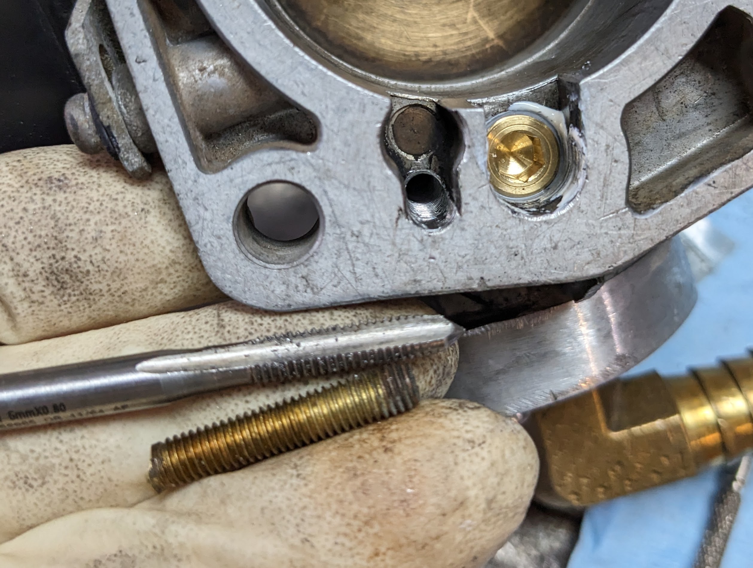
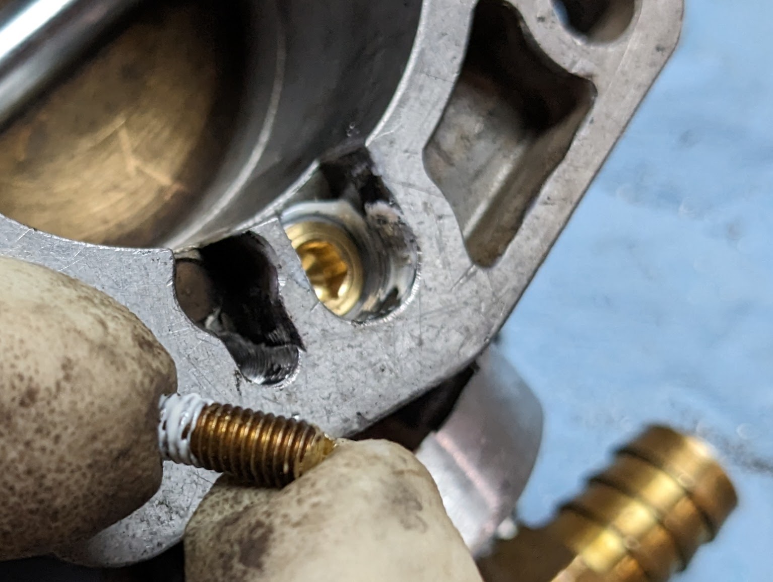
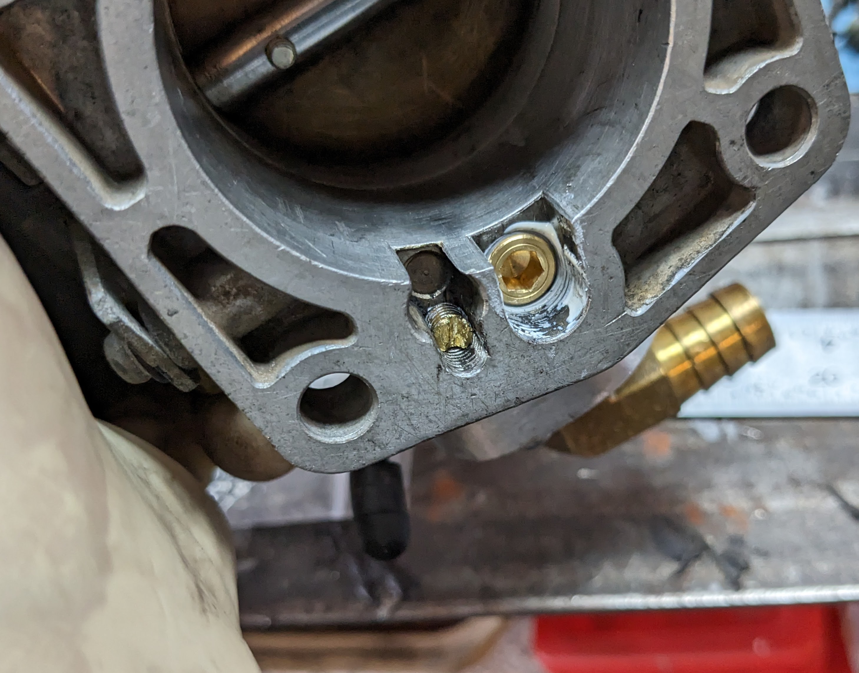
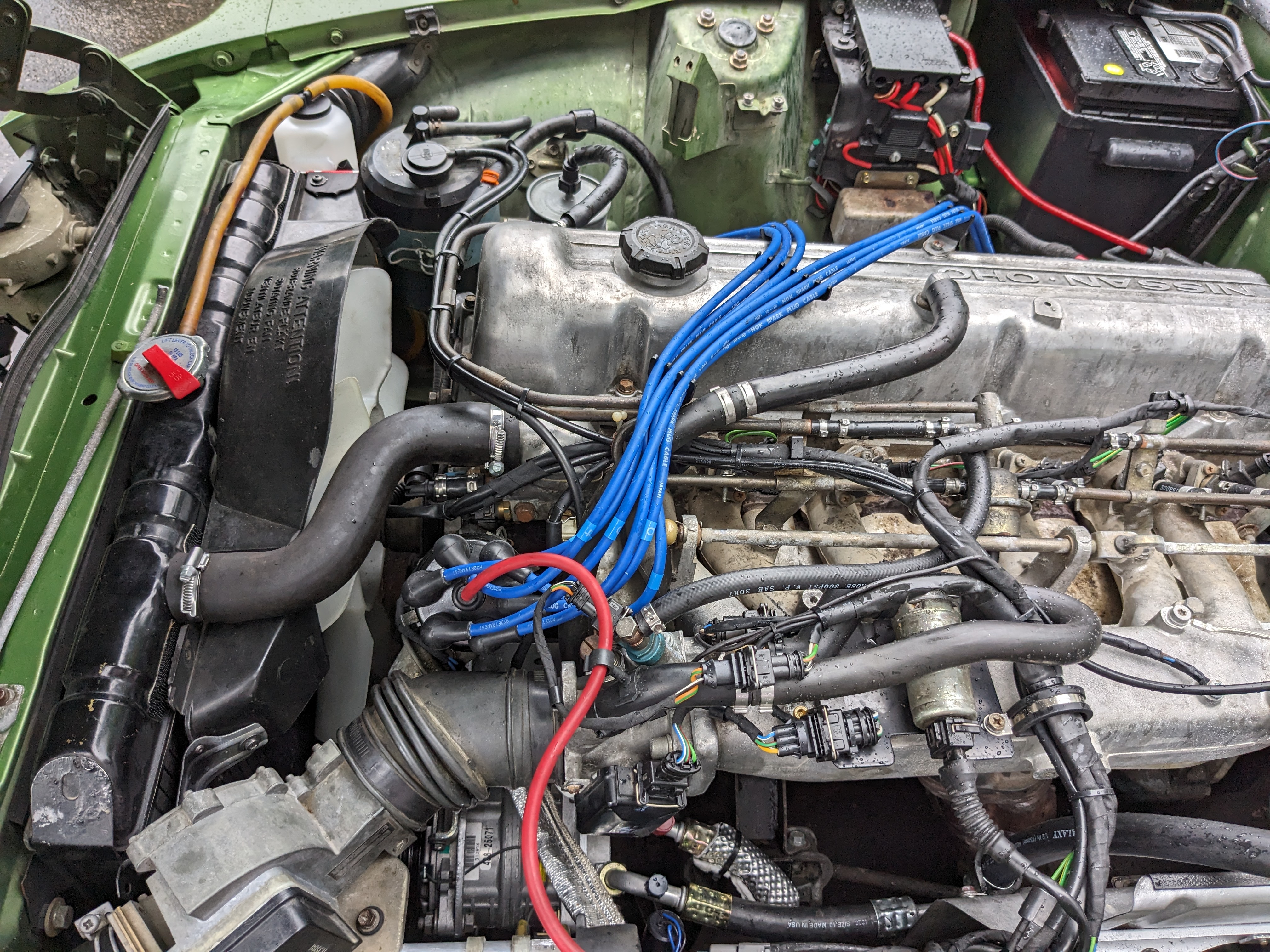
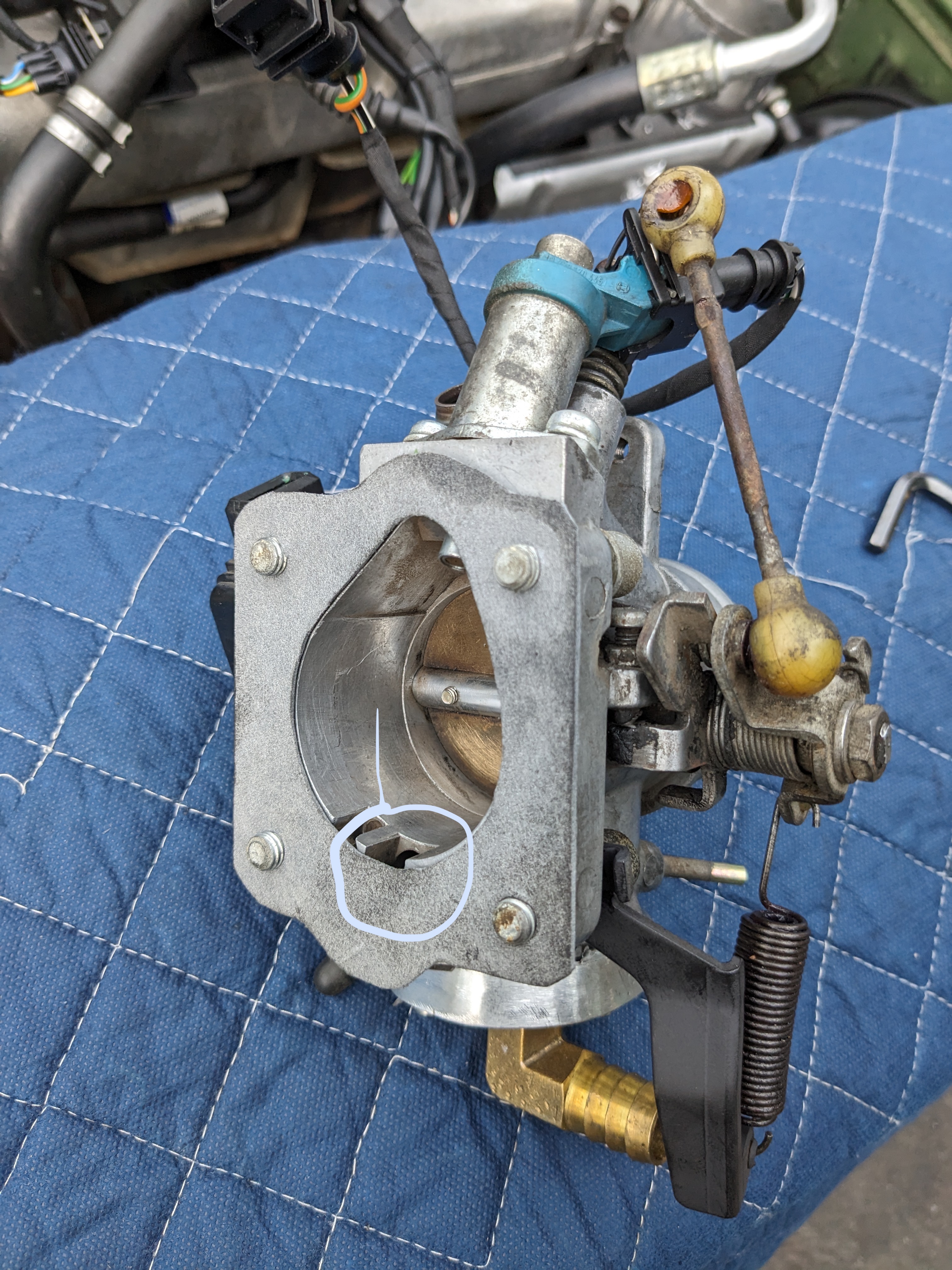
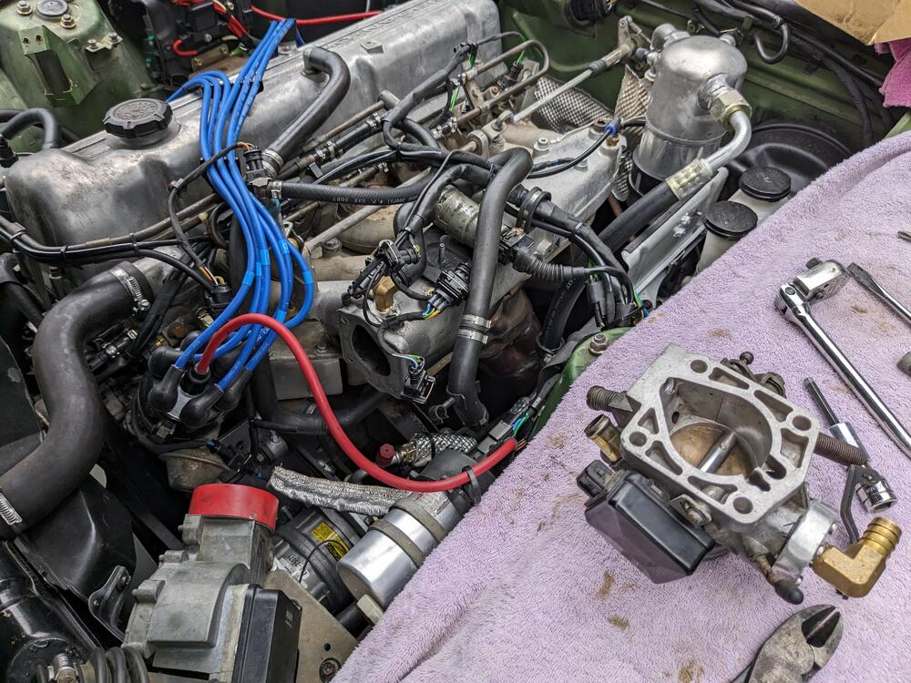
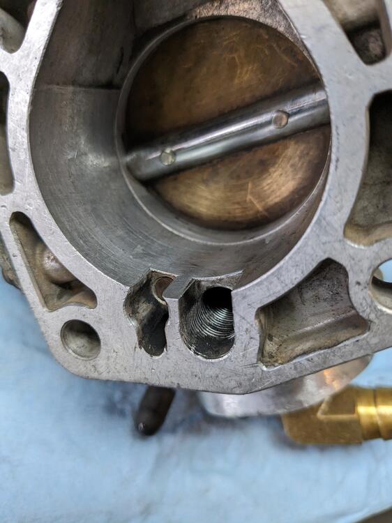
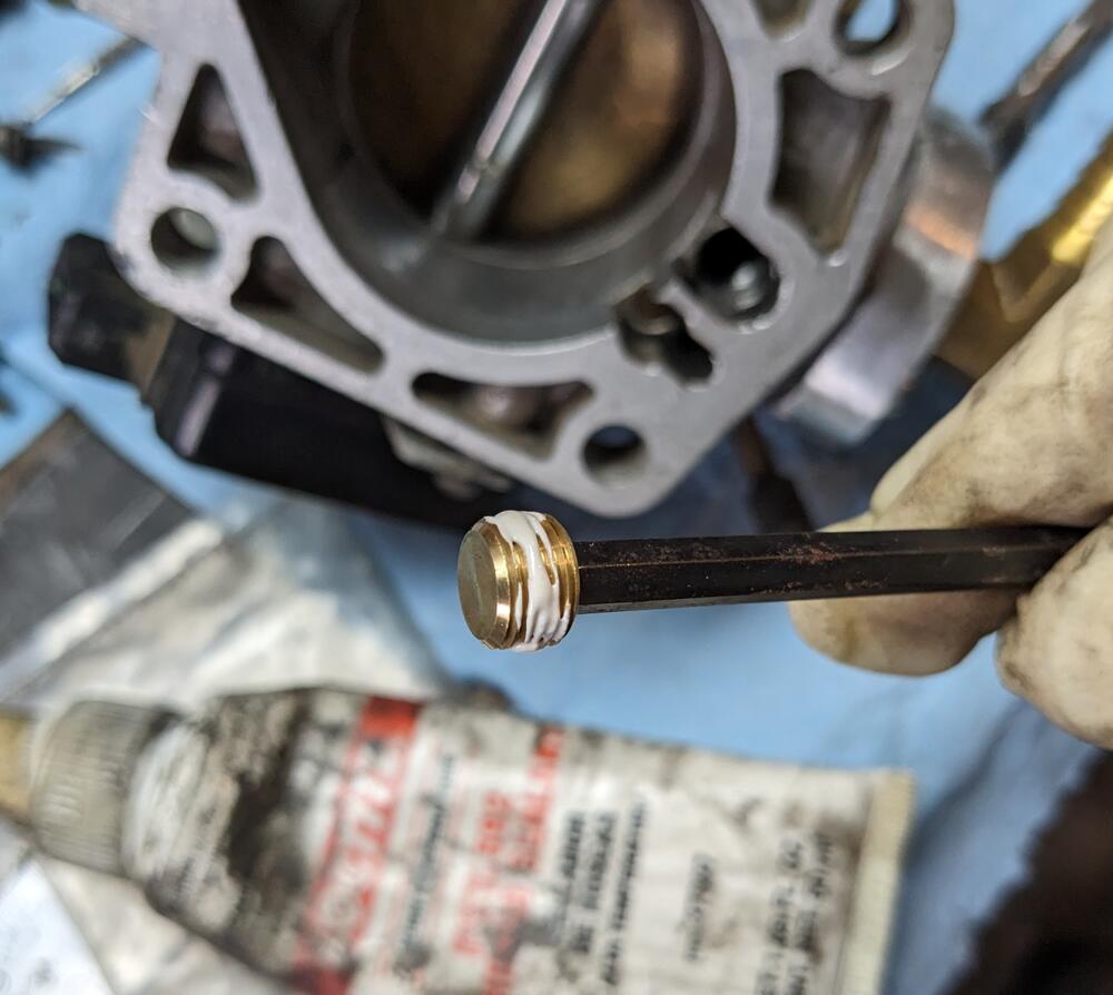
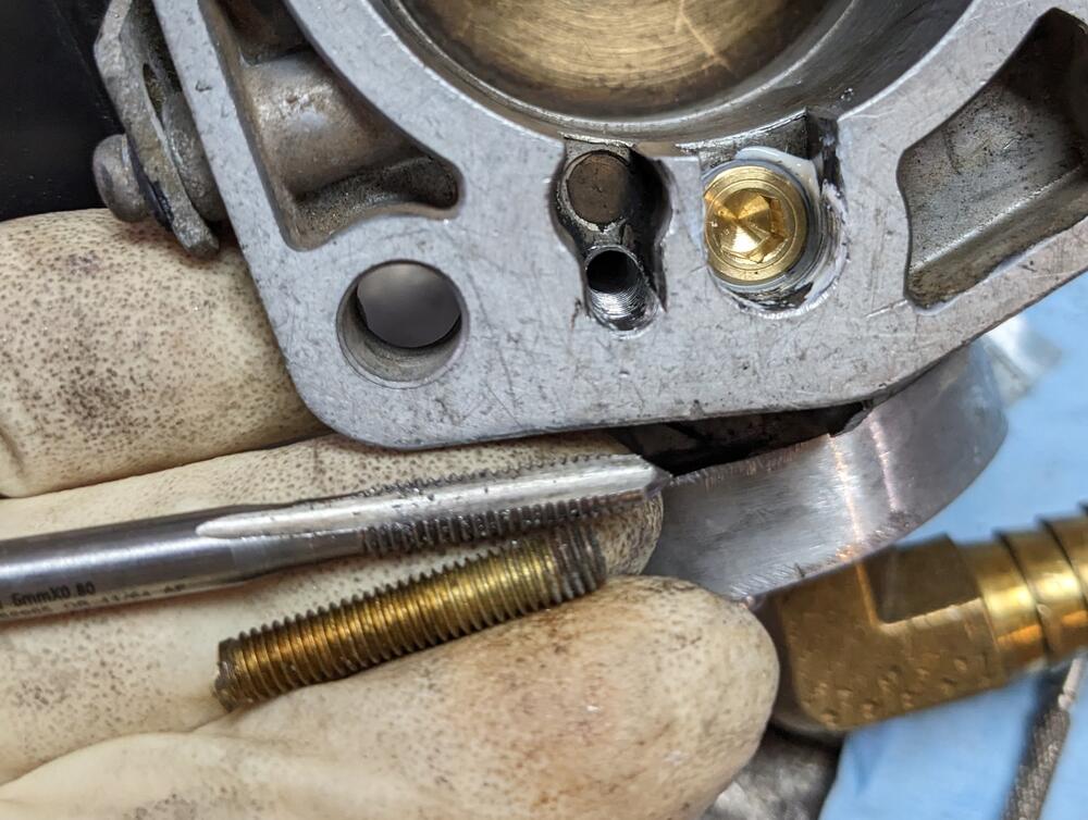
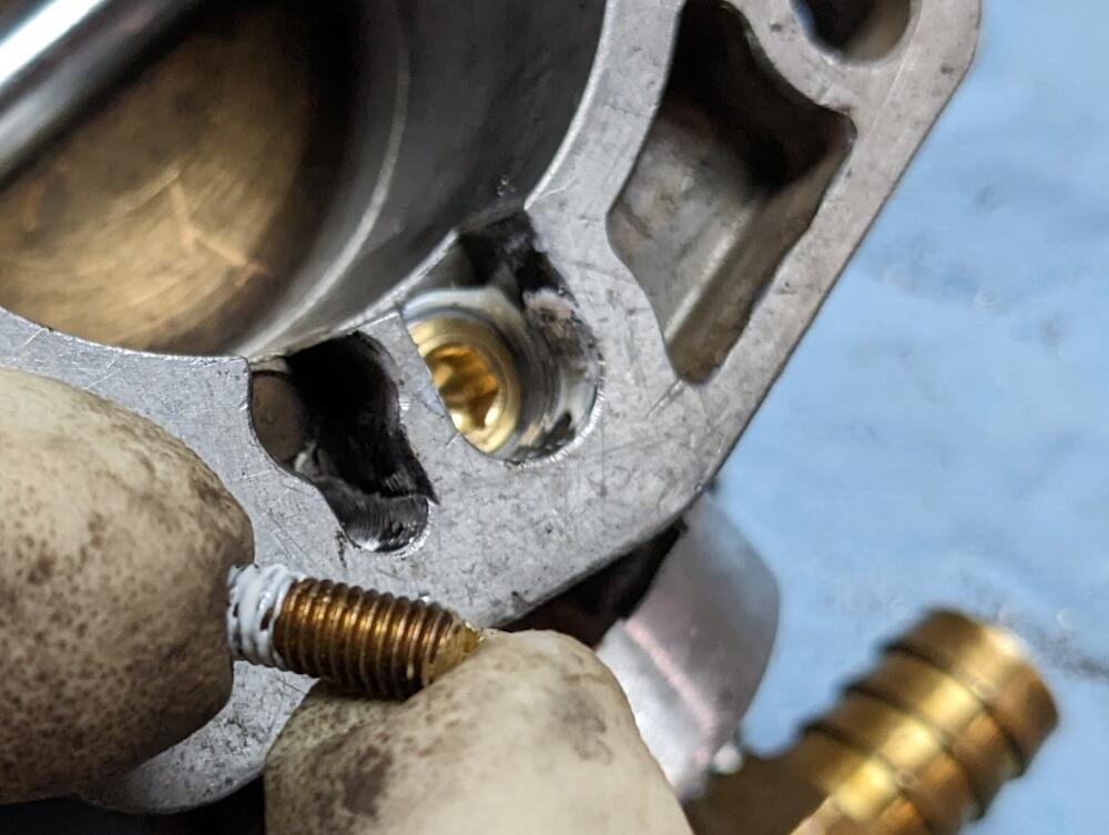
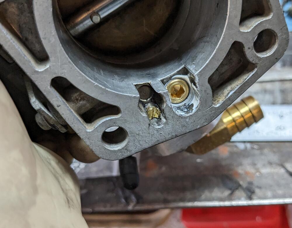
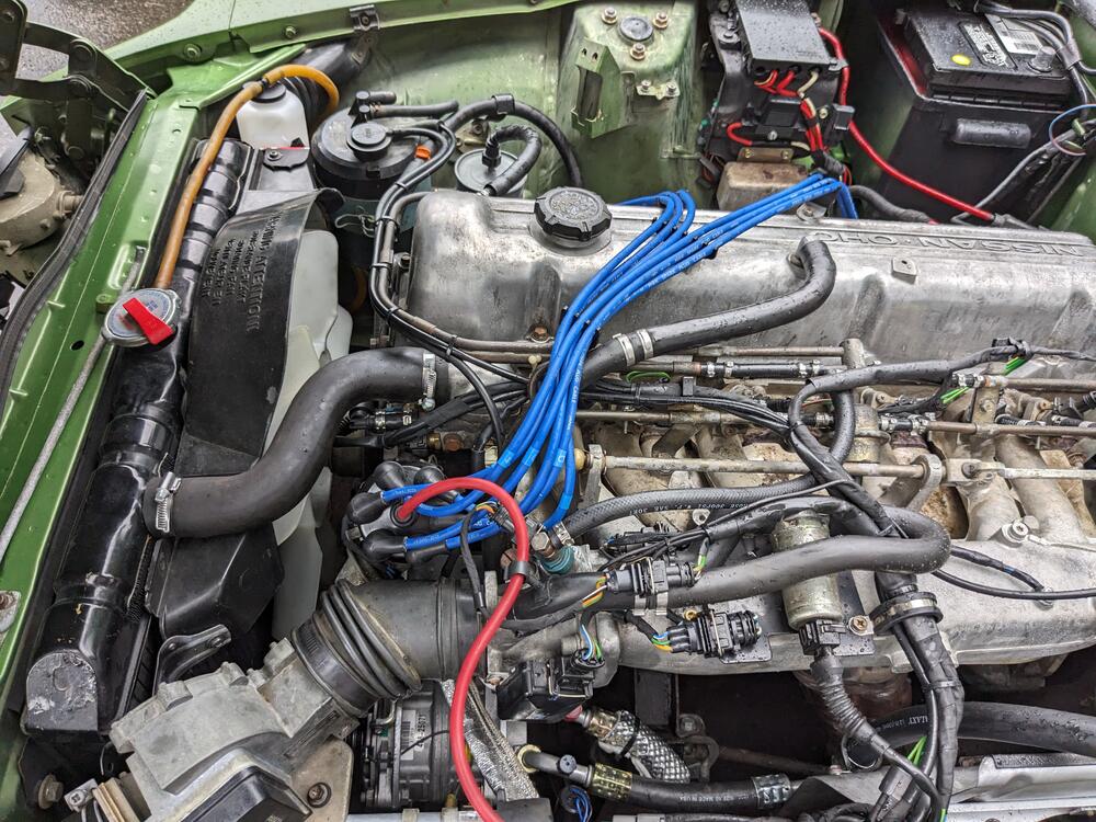
OK - so I had a break in the rain this morning, so I was able to remove the TB during one clear patch, address the ports I hadn't closed off, then get it back on during another break in the rain Larger port I tapped with 1/8" NPT thread sealant on plug tapped smaller port with M5x1, used the snapped off stud from the ignition ballast to make a plug done Back in. Ran the motor - don't have the tach installed, however the rpm's felt much more in line. A little low perhaps, so I ran it to normal op so I could check the base setting. With CIS, the easy way to do that is close off the low vacuum tube from TB to the IACV. It stalled out, so base was too low. Opened the idle thumbscrew a couple turns (I had completely bottomed it out) & got the idle what felt around 750. Releasing the tube, the idle motor cycles & the idle rises to what feels like 850-900 range. I will set it more accurately once the tach is in, but it feels good. Motor revs freely & returns to idle.
-
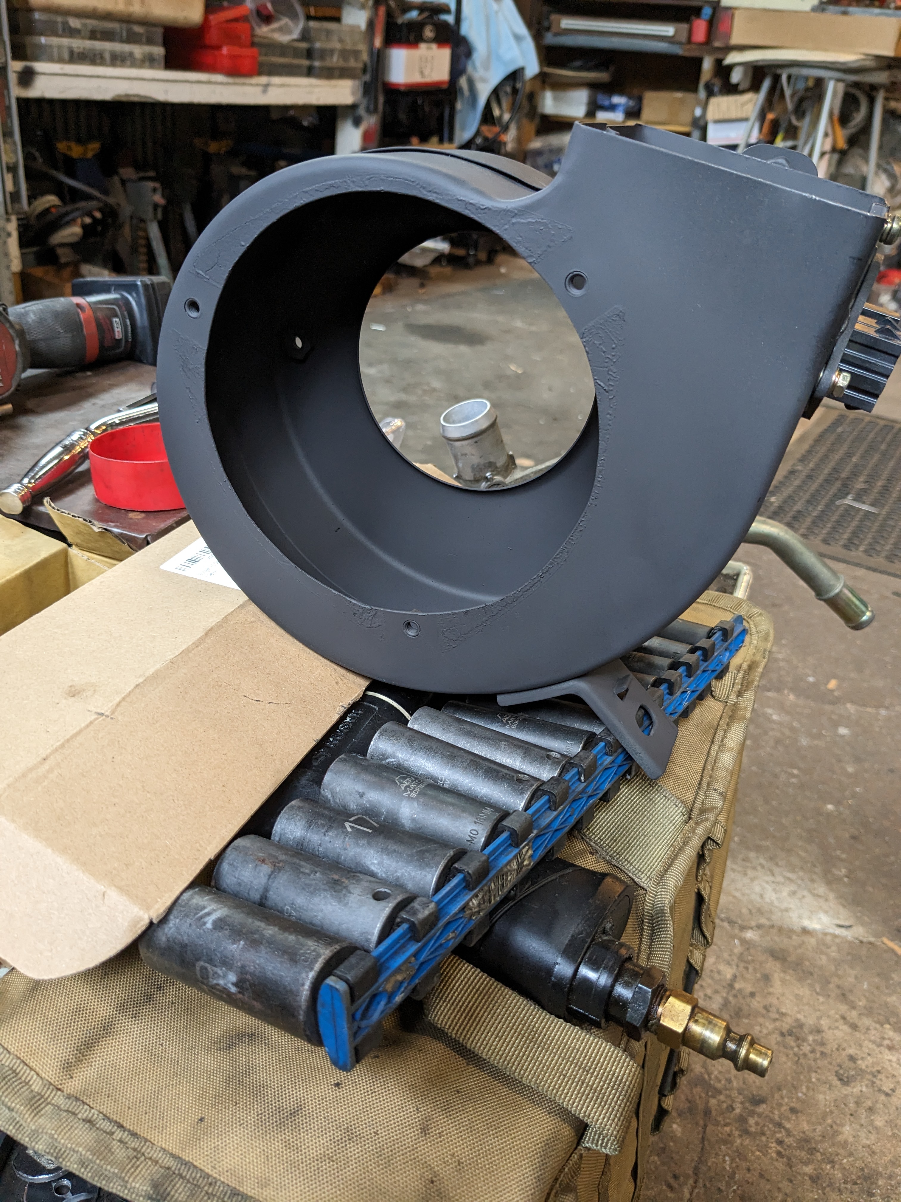
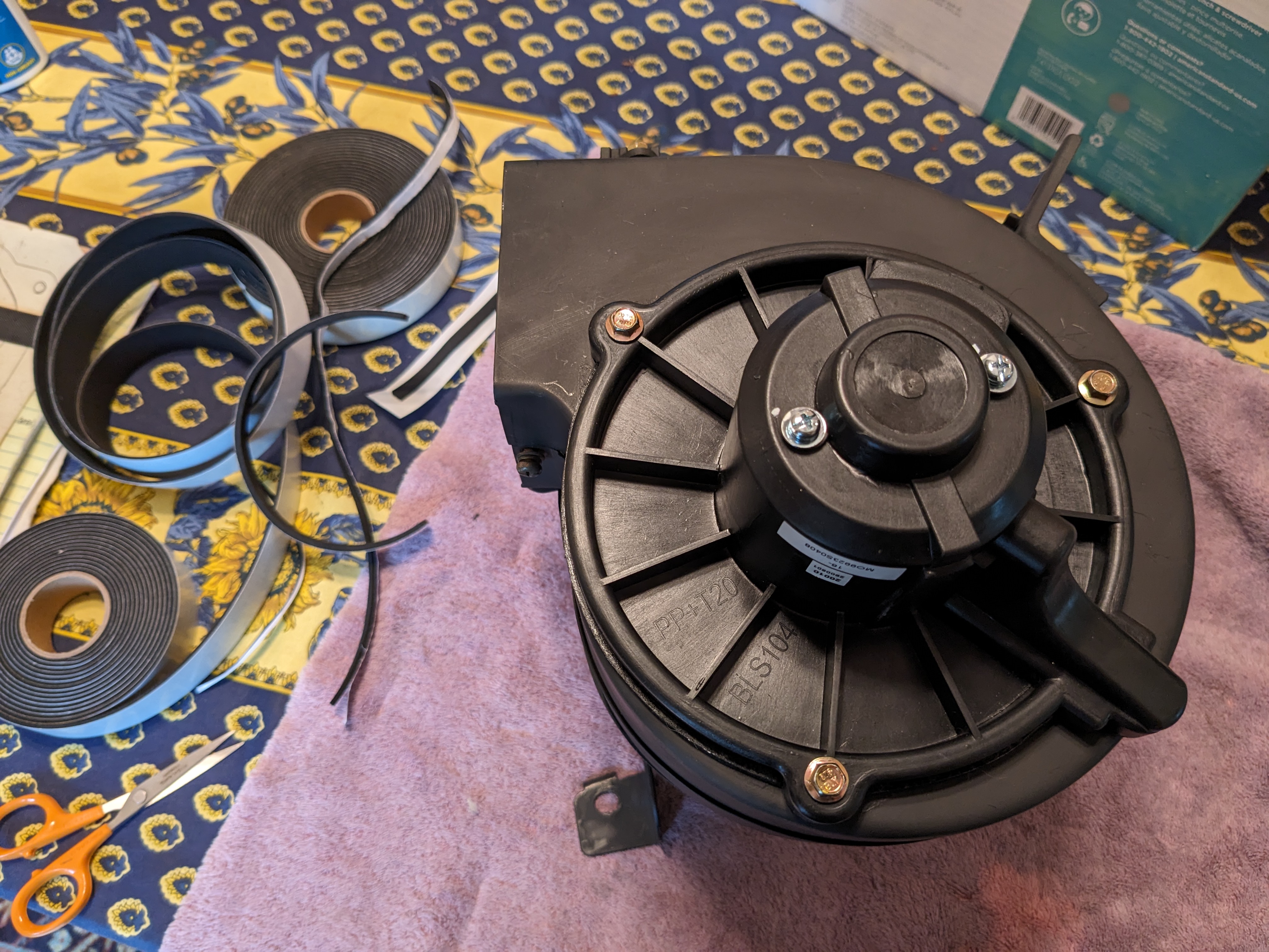
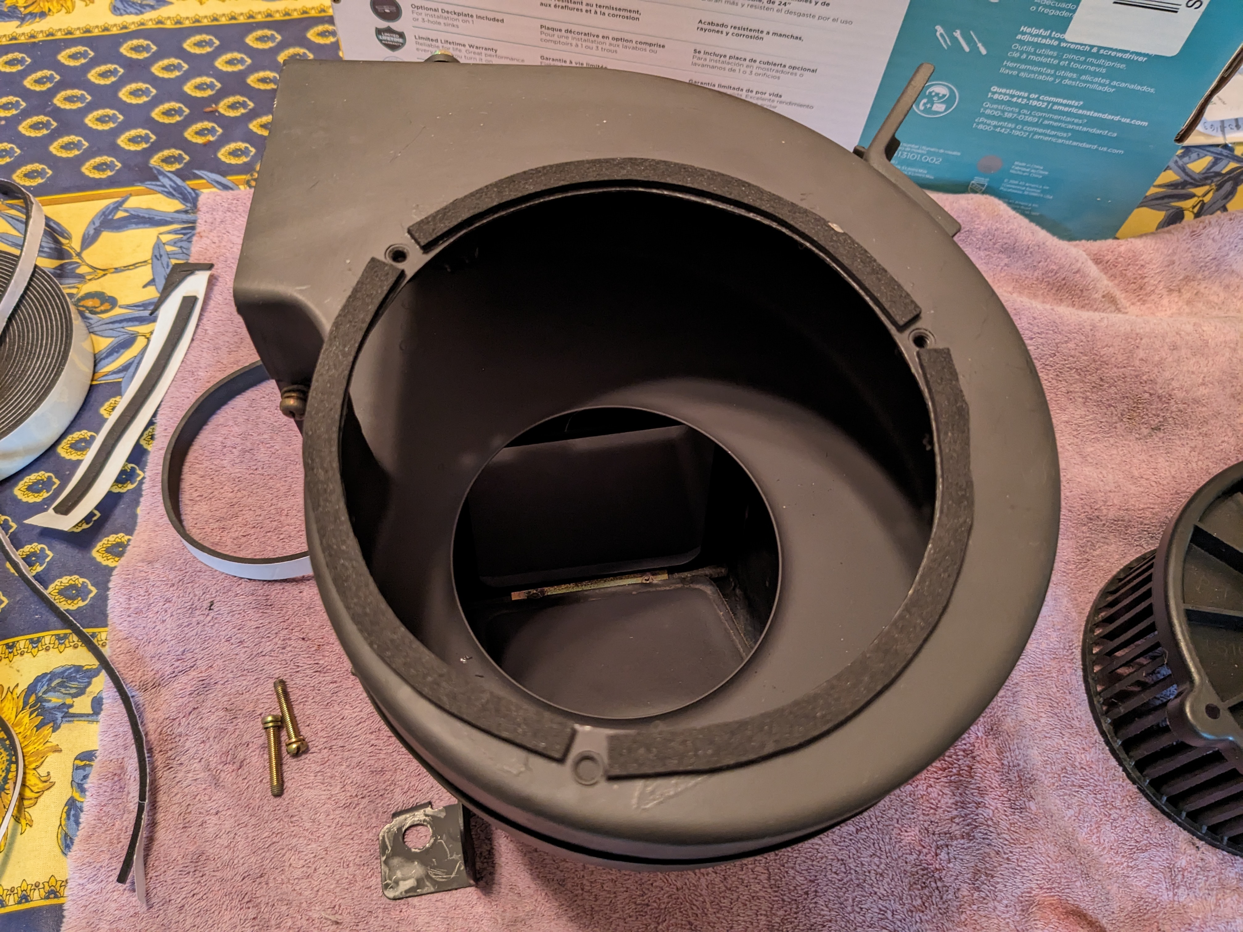
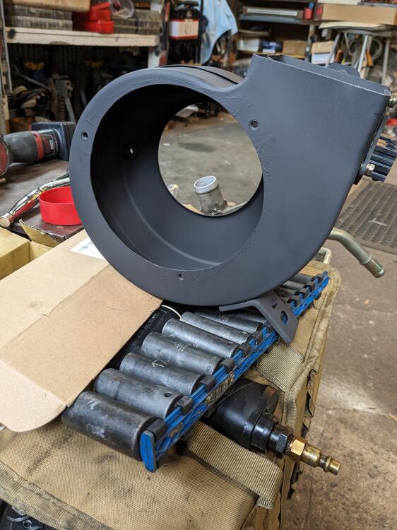
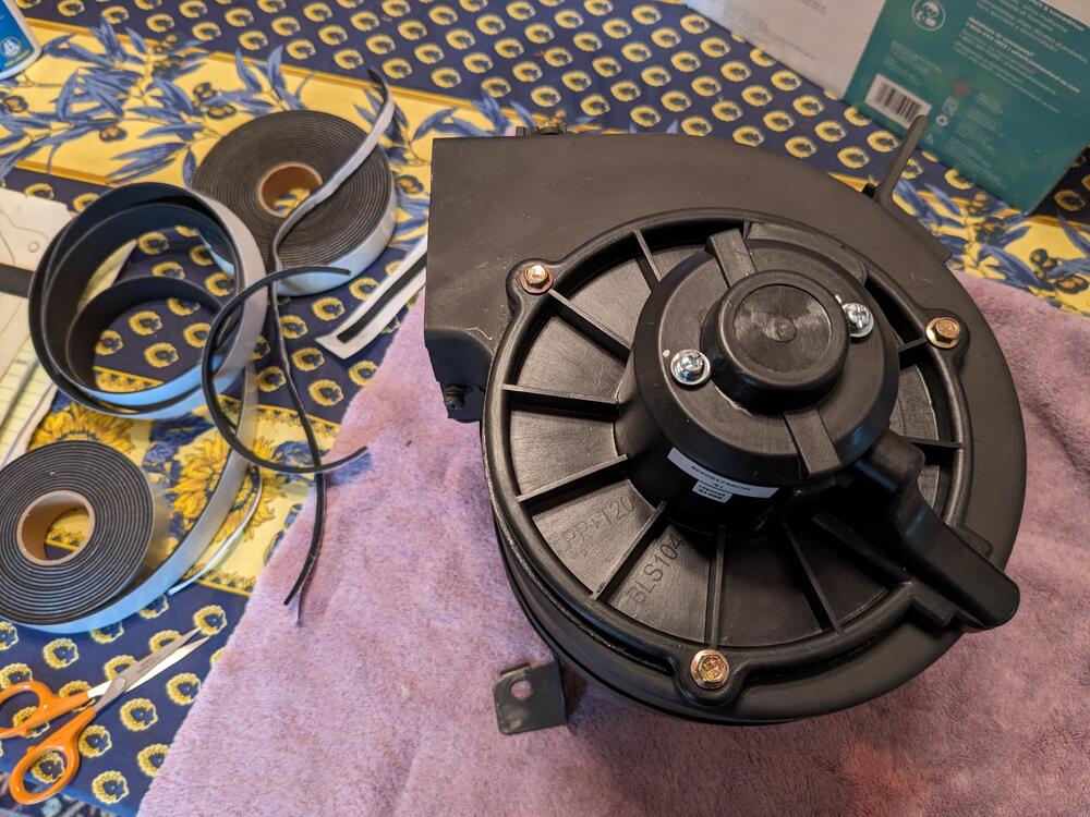
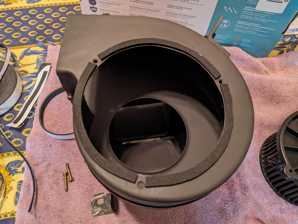
prepped & painted The blower needs a cushion - I put closed cell foam on the housing first - that didn't work so I transferred it to the lip of the blower motor outer flange The stock bolts were too long now, so I switched to shorter M5 hardware. Bolts line up with stock holes, no mod to casing required squirrel cage offset
-
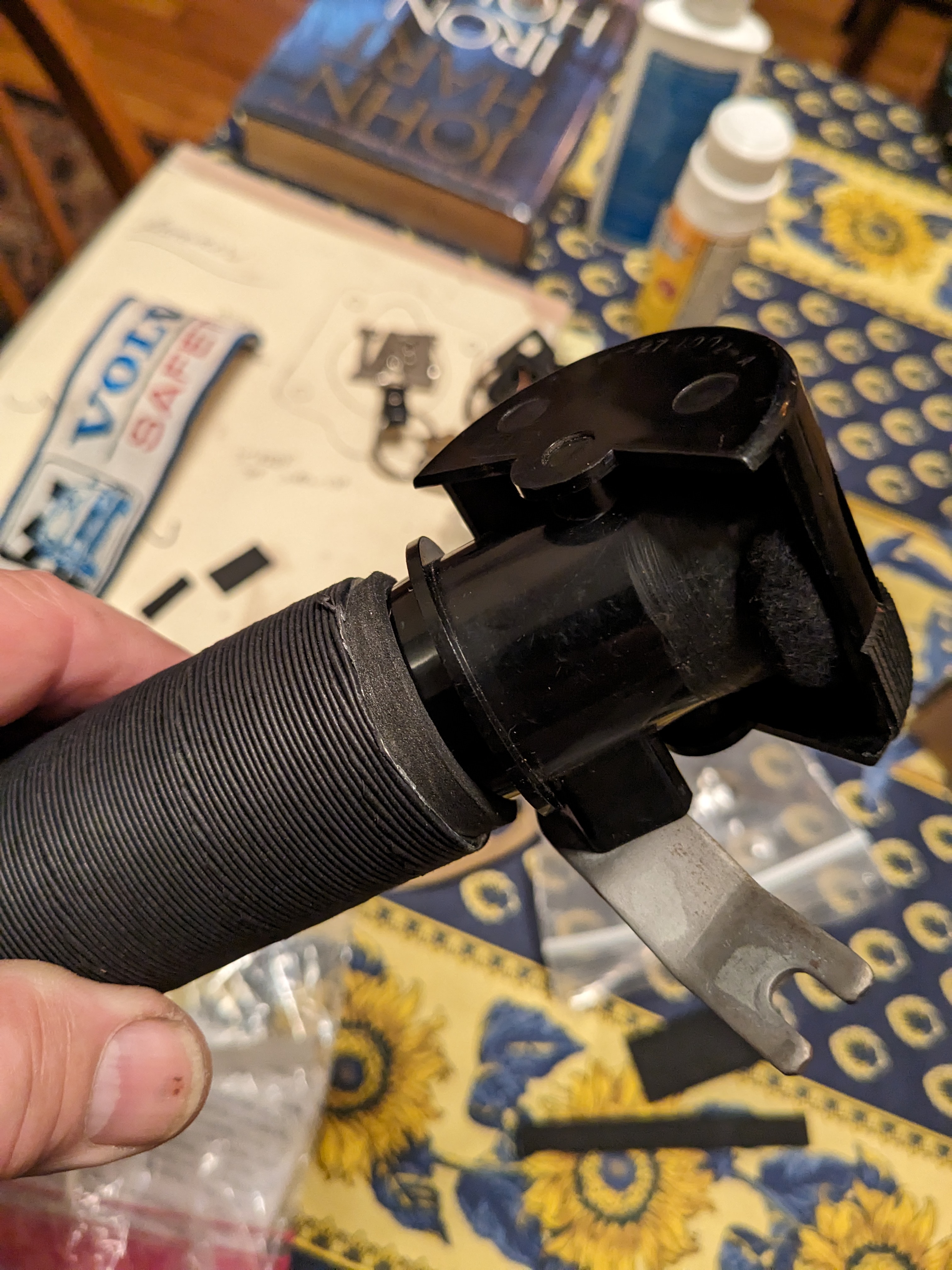
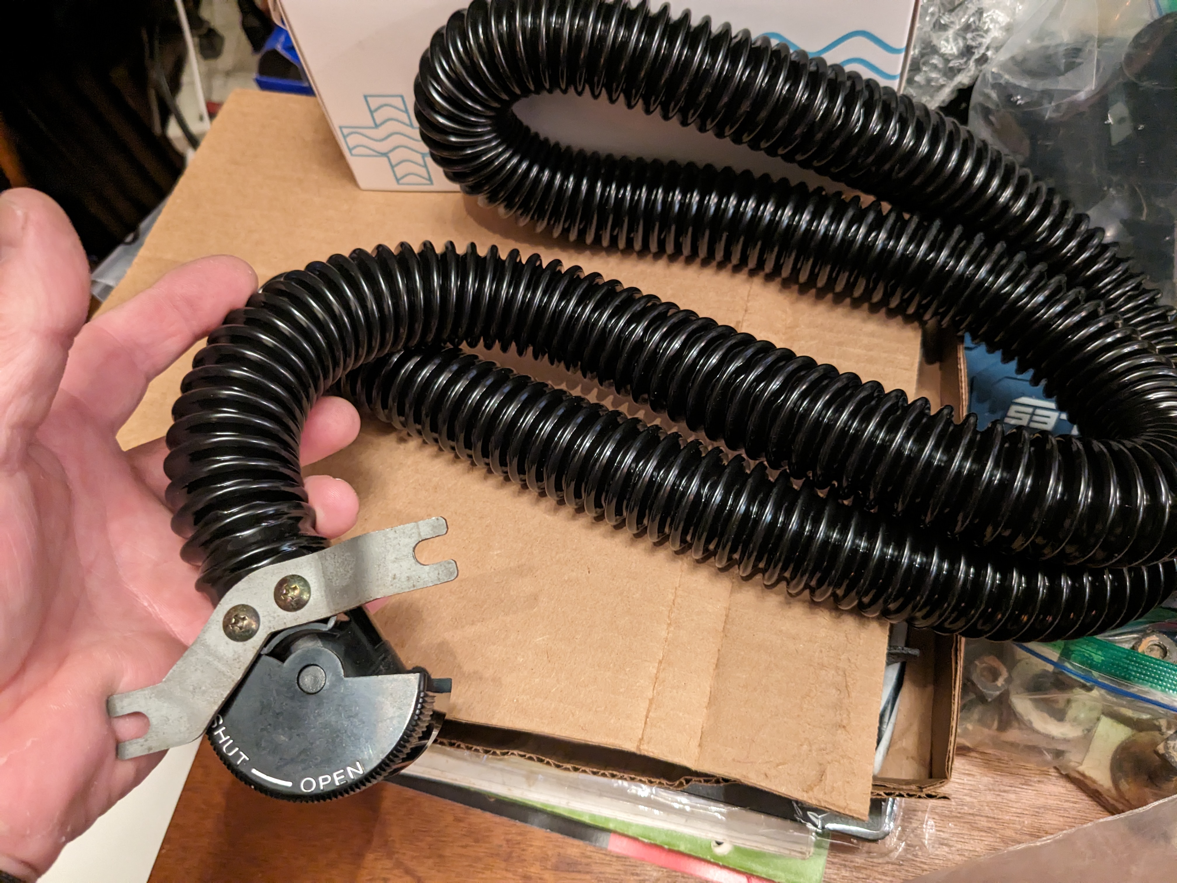
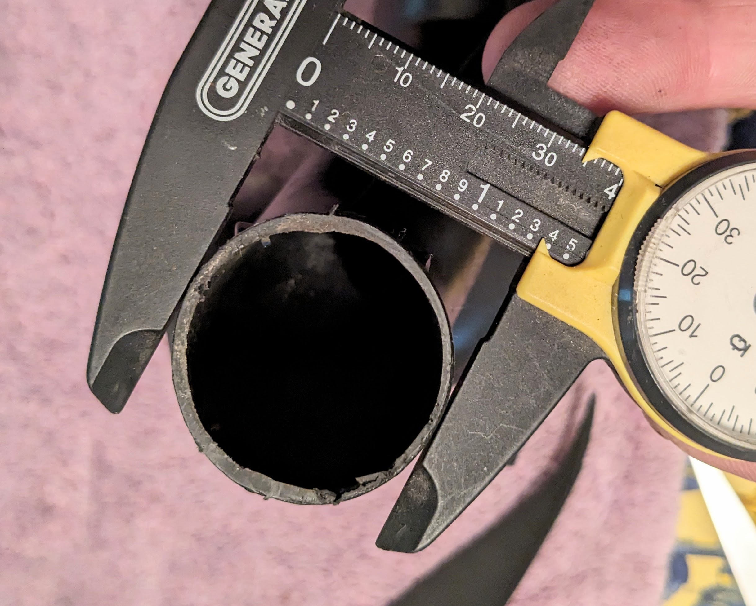
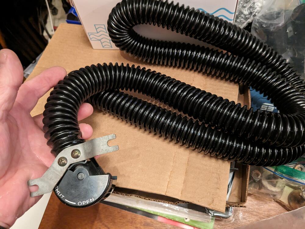
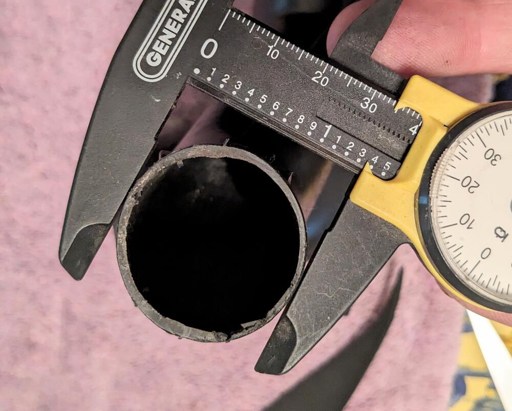
I bought the Dayco 80165 hose based on this thread, however it doesn't fit the pass vent or either of the elbows - those are all approx 1.4" OD. The DS vent is slightly smaller ID for some reason - I was able to stretch the 1.25" Dayco hose over it, but no way it's gonna fit the other positions. EDIT - ordered Dorman 96030 1.5" hose to try
-
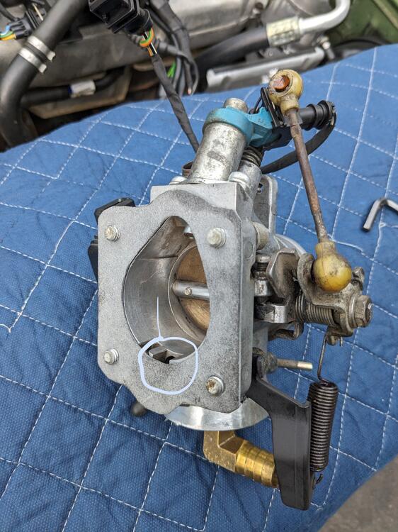
Thanks CO 🤪 By front side I meant the high side vacuum port that faces into the plenum at the flange - should be easier to plug that that the underside, as I'm using the now larger low side for the vacuum draw on the valve cover, having enlarged that orifice, I'm not sure plugging the now smaller inner/central orifice will be so easy from the underside. EDIT - I did also check the ignition timing, as I think it was mentioned that doing the HEI mod can alter the base timing - it was still around 12º-14º, as far as I could tell, not 15º-20º, for instance. Given the current high idle rpm, I'm assuming it may be slightly over normal base setting.
-
There you have it. I'll remove the plate I made & plug the front side port. Thanks CO!