HusseinHolland
Community Member
-
Joined
-
Last visited
Everything posted by HusseinHolland
-
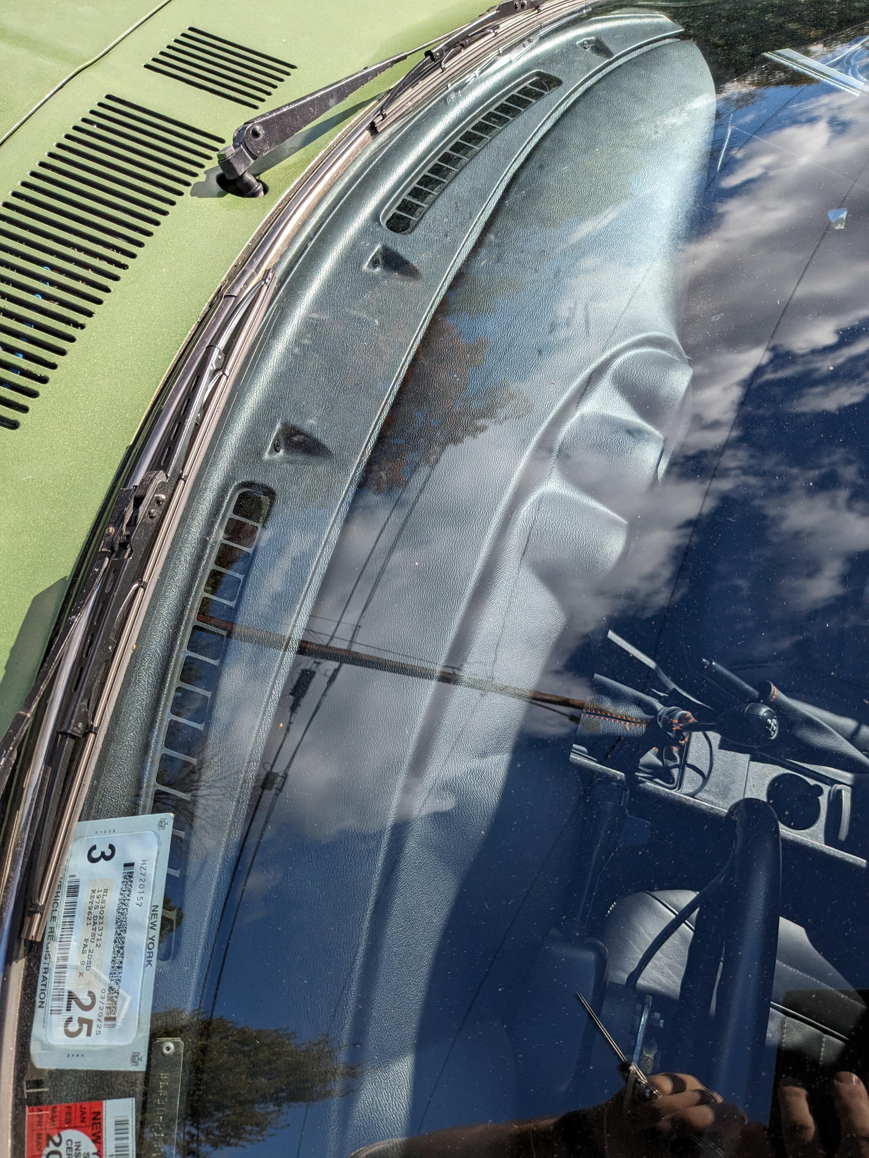
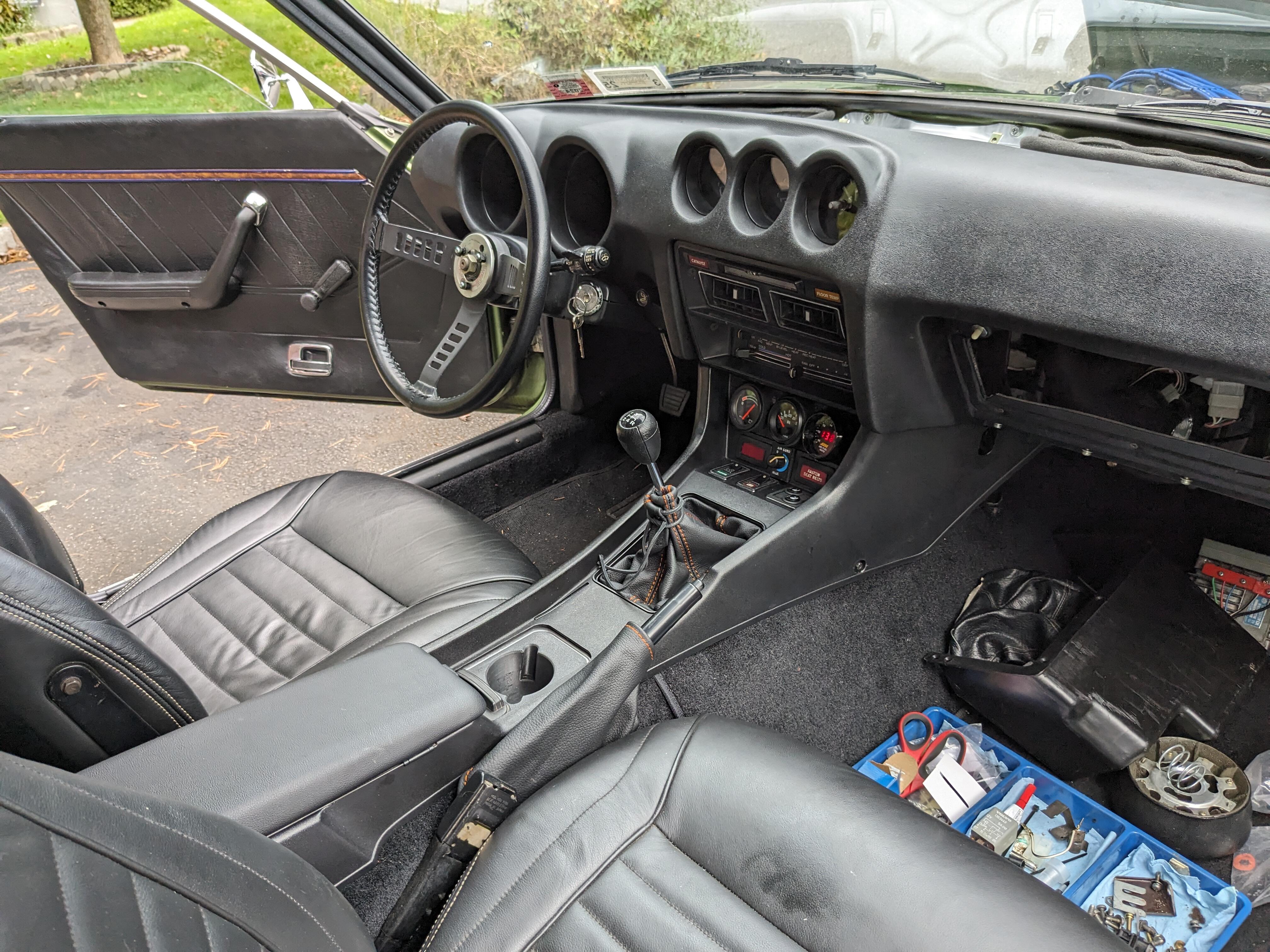
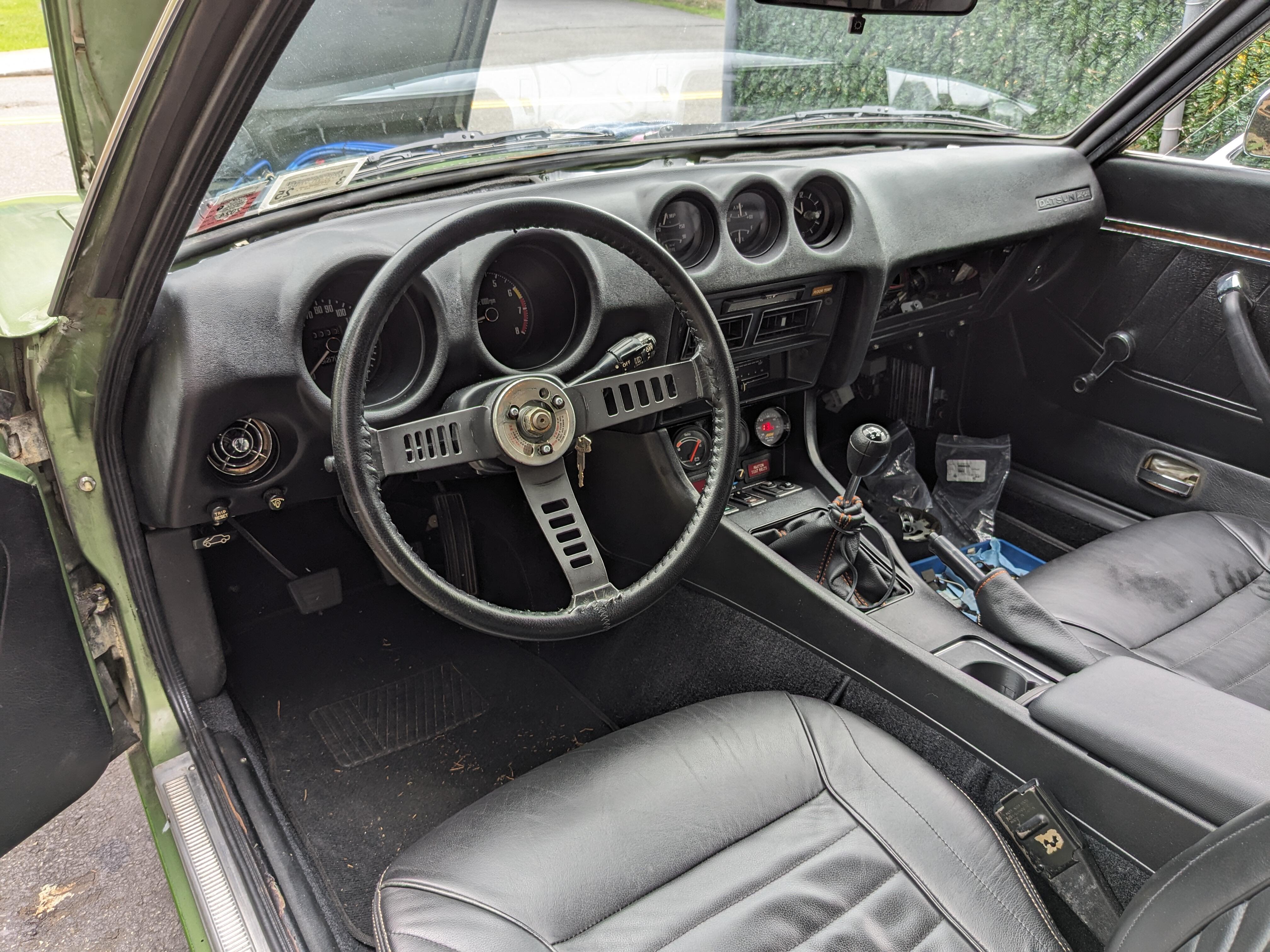
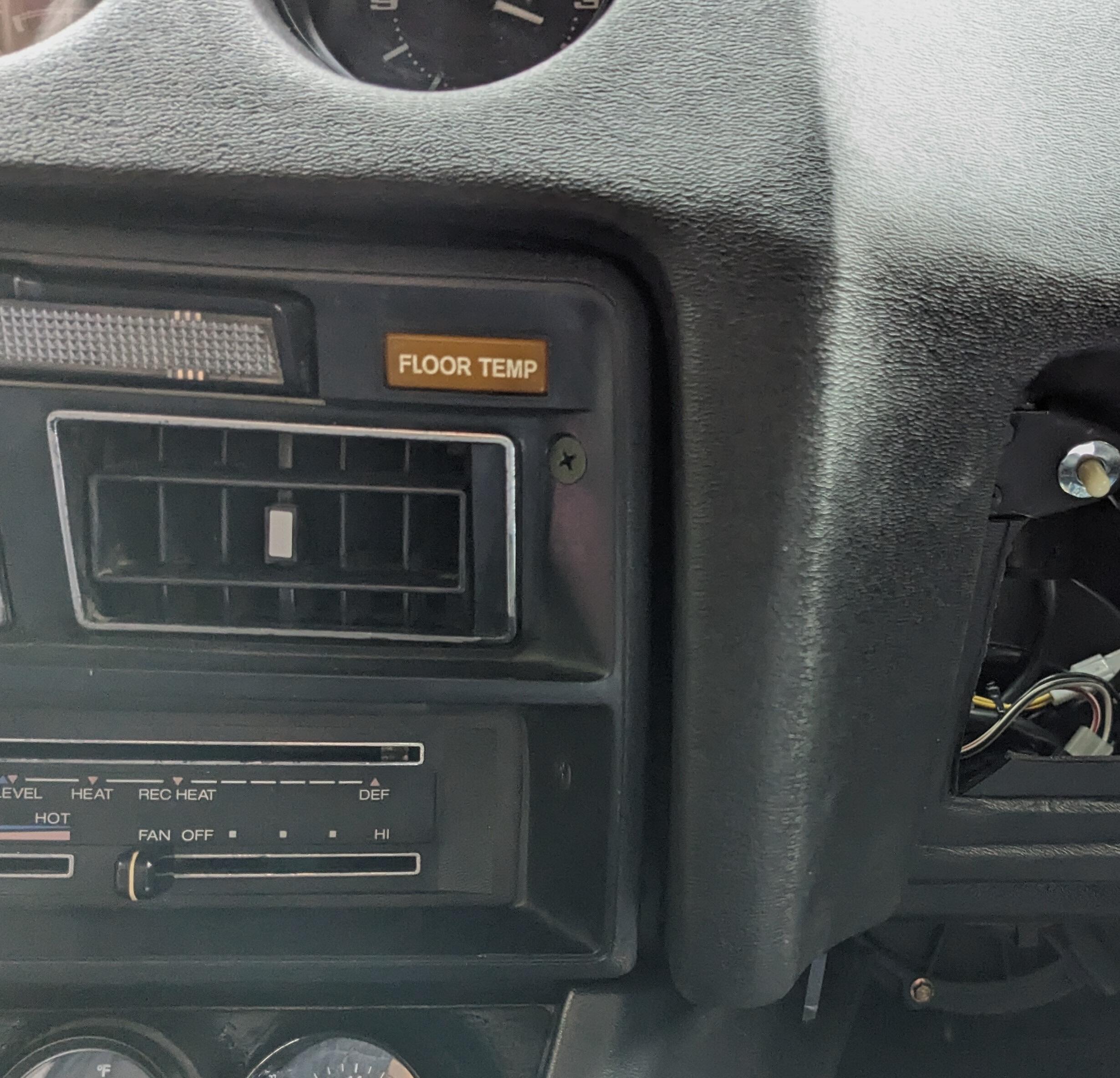
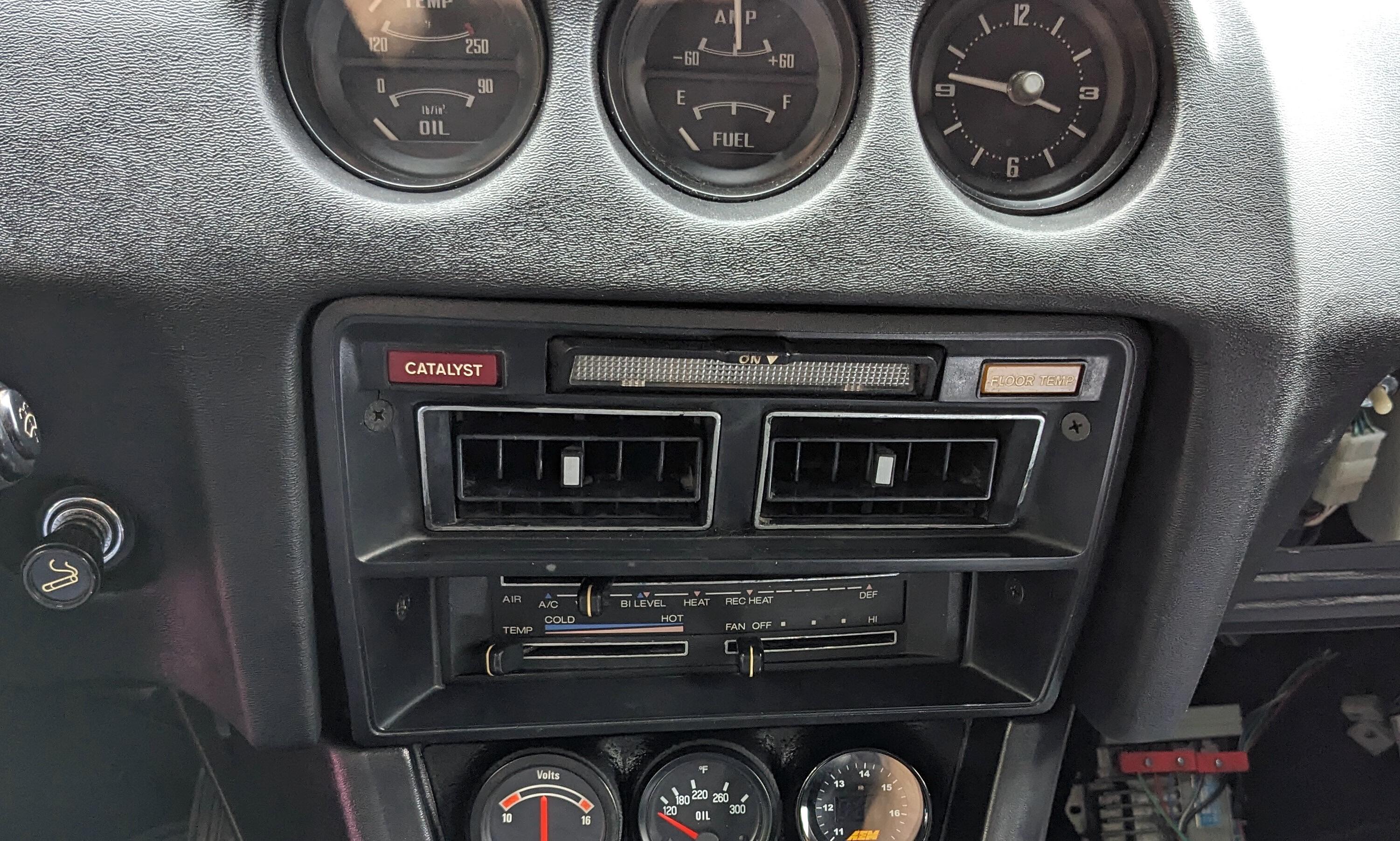
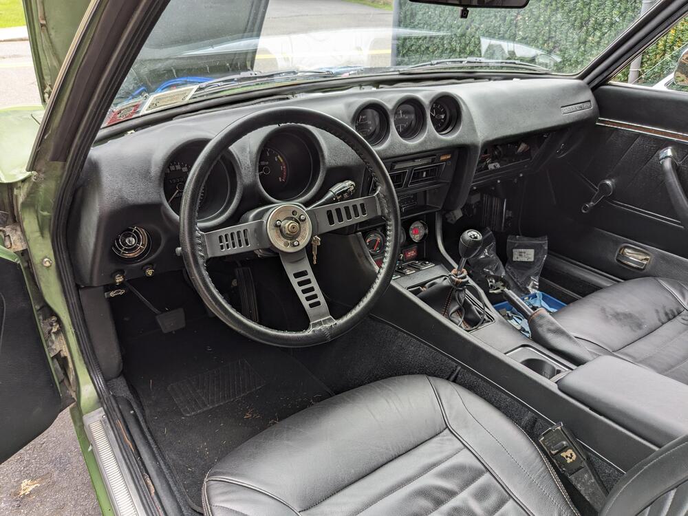
Painted & reinstalled the dash vent panel today, and put the steering wheel back. No horn pad, as I don't know yet if it's centered exactly. Can't drive it until the new clutch slave arrives & replaces the blown out one.

-
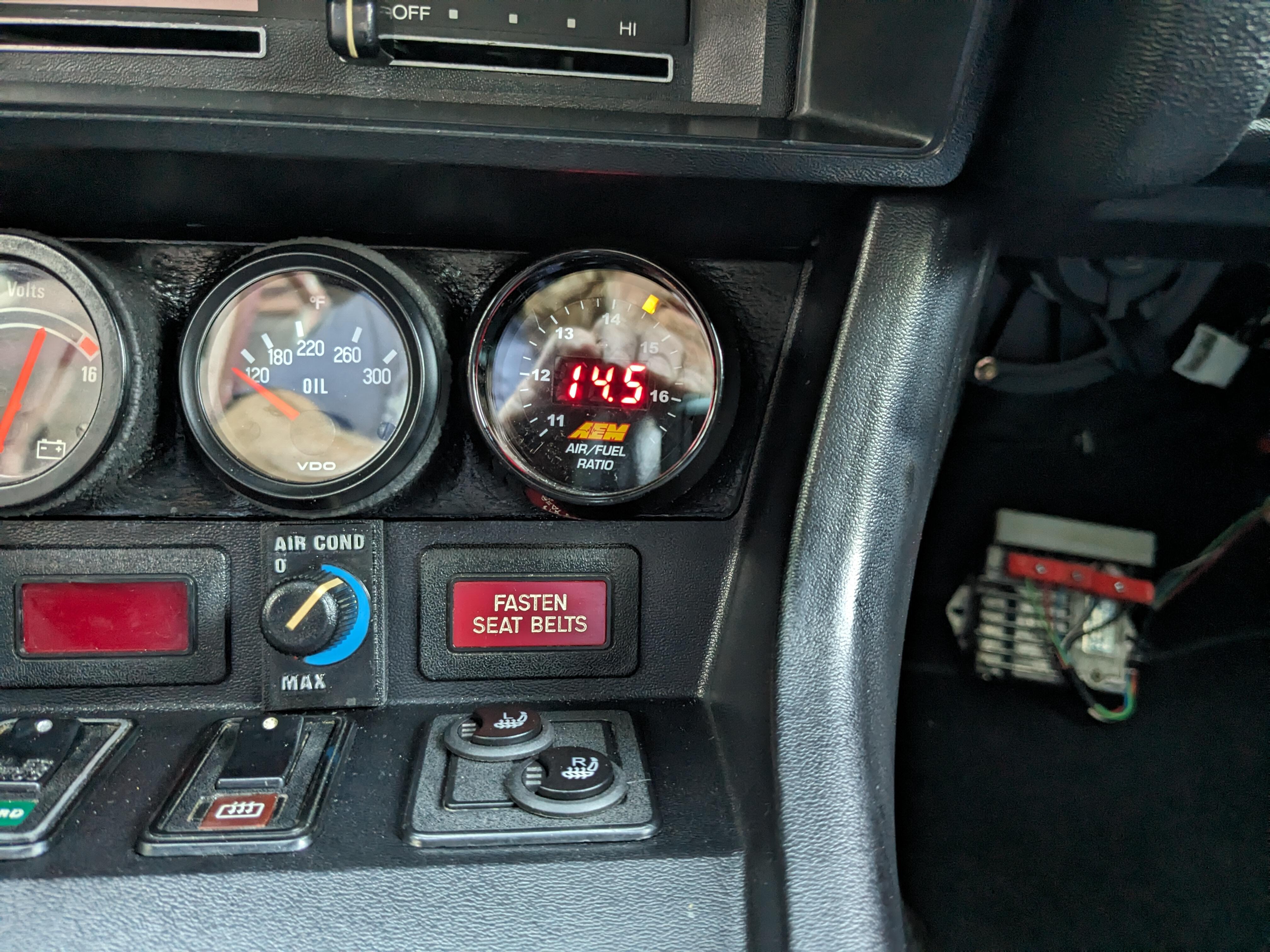
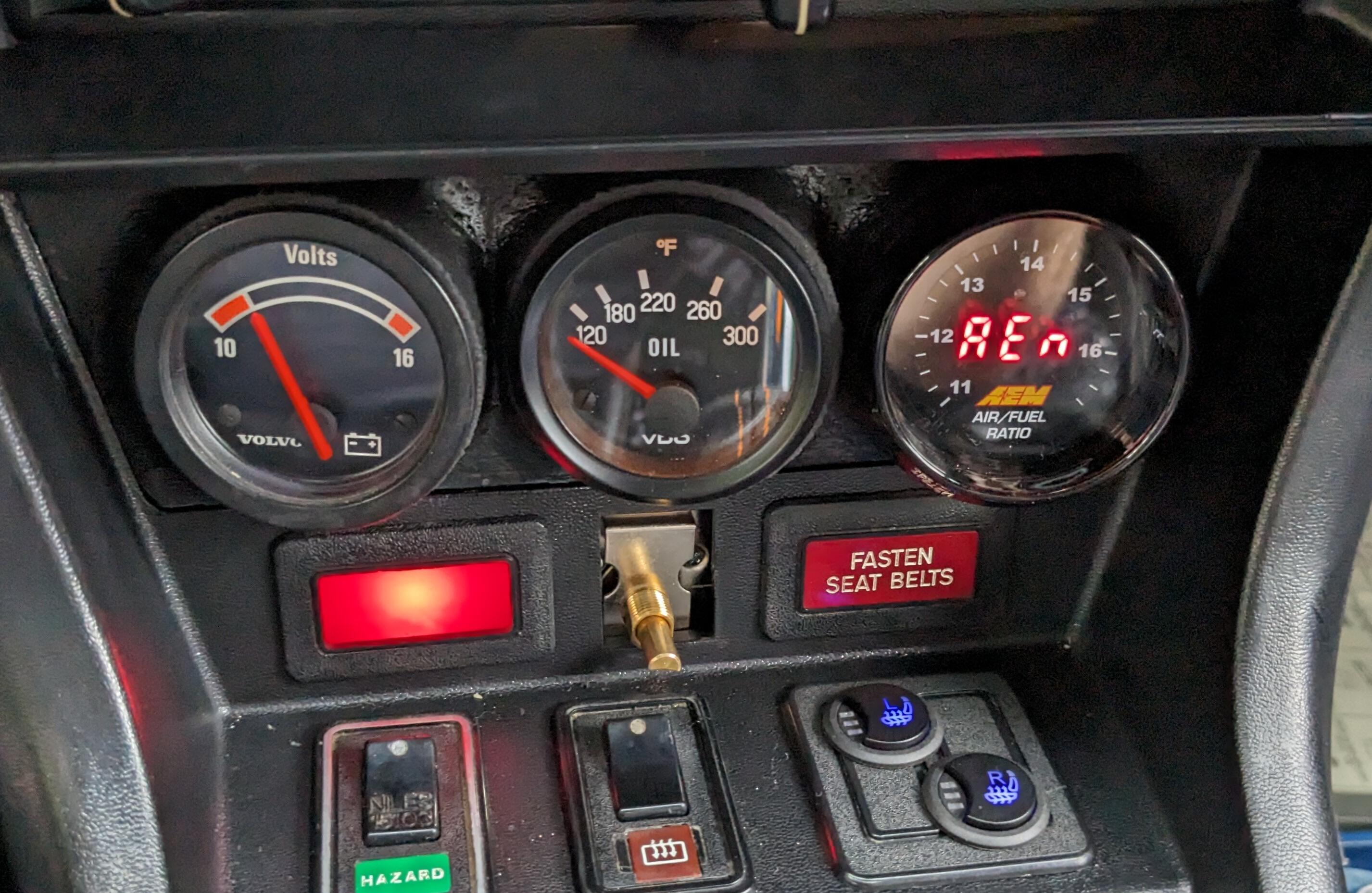
Did a number of things today. Replaced the ECT with a new Beck Arnley 158-0134 sensor. With that, (ambient temp 50ºF) it started well (after the initial delay with priming), and during warmup. AFR's stayed nice & fat, which was not the case with the old ECT. Once it got closer to normal operating temp, the AFR"s went lean again (16's). So, I put in the 1.1K ohm resistor in series with the ECT. With that, warm AFR's are to rich (13.4-13.7) - so I don't even need 1.1K resistance added to the ECT circuit Pushing very slightly on the AFM lever fattened it up a touch, and smoothed the idle quality So, I lessened the wheel tension by 1 tooth Also adjusted the WOT enrichment TPS settings - the factory position brings it on around 30º opening, so I moved it to closer to 50º Stock adjusted Reset (lowered) the base idle closer to 800rpm, with those changes the AFR was sitting around 14.2 So, I installed the 2.2K potentiometer, wired the 1.1K as well, but decided the 2.2K would give me more range. Since 1.1K puts AFR's at idle around 14.2, I need somewhat under 1K to get the AFR's in the 14.7-14.9 range at idle. Bolts to the left dash frame support Used a 2pole HD090 series connector to join the pot to the ECU. Removed #13 wire from the ECU connector, now that goes into the pot, pot output goes to pin13. Set dial on POT so that 1K ohm is with #1 at 6 o'clock where I can see it Full value (2.2K) puts dial @ just over 5. Unlikely I will ever need to use that end of the scale. Connector tucked up above ECU Warm engine, setting dial to 0 brings AFR's to 14.7-14.9. I'll see how it starts & warms up with that setting tomorrow after work. Still can't drive it to see how it performs on the highway cruising, due to the blown out clutch slave.
-
I don't have to worry about that - I'm going to do a drivetrain conversion on mine 😄 So, I made a couple of resistor plugins - one 2.2Kohms, the other 1.1K ohms. I'll try them tomorrow & see which runs better. I ordered a couple of POTs, one 1K & the other 2.2K, so depending on which resistor seems to run it better, I'll add the pot so I can tweak the value to make intermediate adjustments. I guess I could just use the 2.2K POT, but I don't know if makes a difference to sensitivity of adjustment.
-
Thanks to @siteunseen for linking this in the bad AFM thread - bumping it so I don't have to search for it, as I'm going to follow her layout, wiring the pot at the ECU harness just have to recheck the two pins for the sensor - 13 & the ground - looks like 16, 17, 35 & 5 all tie together so I'm not sure it matters which I use Edit - never mind, forgot that this is placed in series, not parallel 🤪
-
Reading through the whole thing - she gets to the POT input at post 57, after all kinds of futzing with the AFM. Seems like I should leave the AFM alone, and just do the POT. Important details, post#66 Edit - forgot to say - I wish RadioShack still existed - I used to get all my electronic projects odds & ends from them. I guess there just were not enough of us to keep them afloat 😞 EDIT - in post 57, she says: "Anyway, I ran upstairs and grabbed a 5k variable resistor and plugged it into the temp sensor connector. That let me tweak the mix manually. I found that the best mix was achieved in a warm engine with a resistance of 2,550 ohms, while the temp sensor's resistance had dropped to 240 ohms. Thus the mix could be richened about right by adding 2,310 ohms in series with the sensor. Interestingly, I think I remember the value of the previously added resistor being 2.2k, so apparently someone else had been down this road before me. I'm sure at one time it made the engine run very well, and then it got wonky again with age and deterioration." I only ordered a 1K pot, I'm wondering if I should get one that goes at least into the 2K range....
-
Thanks for the input. It definitely does not feel right at all, you can feel the lean miss, so I don't want to drive it & possibly damage the engine. The POT should be here tomorrow, along with a new ECT. I can run the motor with the Volvo ECT pressed against the t/stat housing & get AFR's in. good range overall, but it doesn't feel 'right', so I'm going to use the correct ECT, check the AFM values & wire in the POT. Hopefully Sunday. Tomorrow is gonna be rain all day. 😞 If I have to, I'll mess with the AFM adjustment. I don't want to spend too much $$$ on components like that, as the whole mess will go away when I do the VQ35DE conversion in a year or so.
-
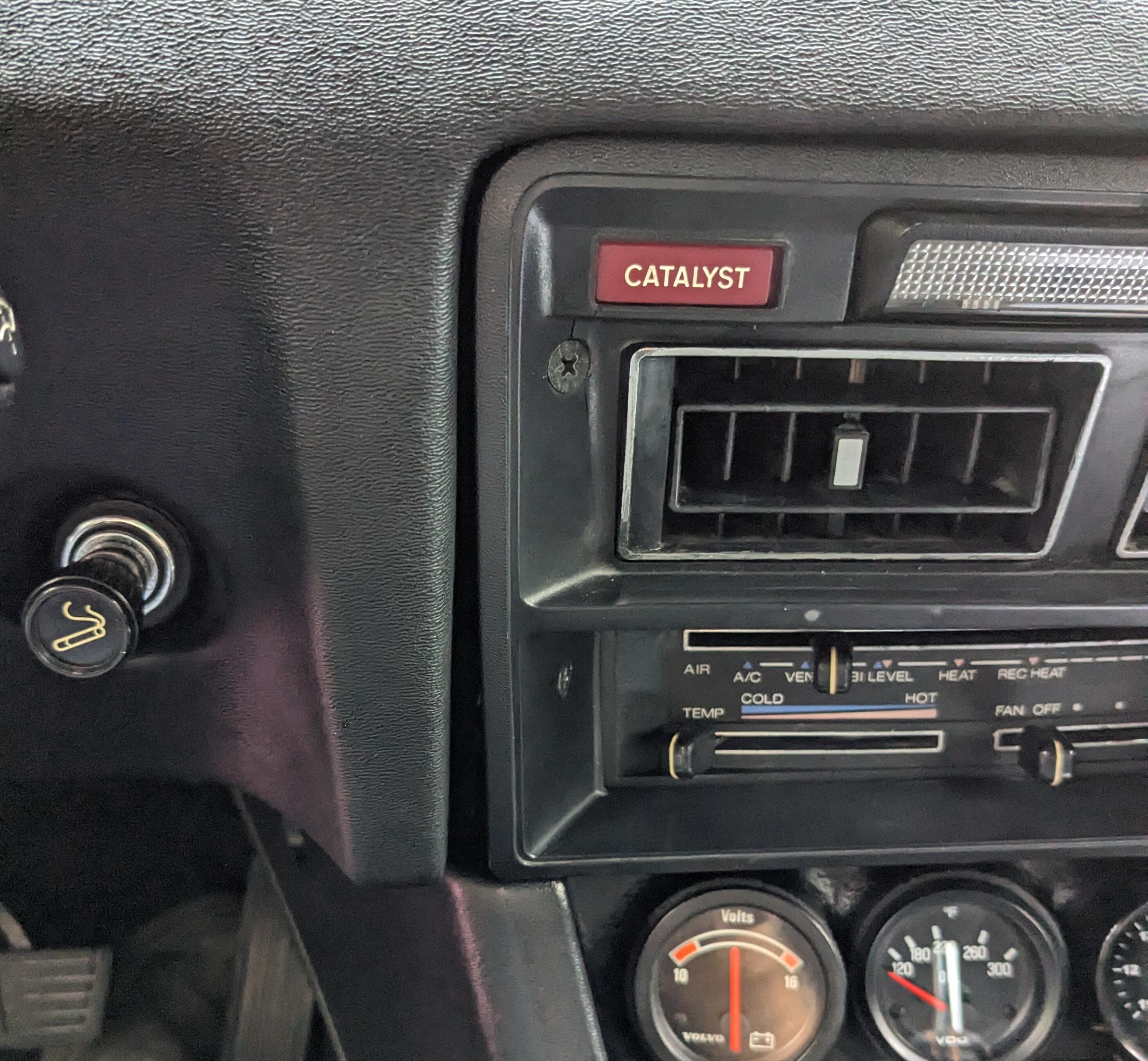
Back to the duct work. Had to do this before the steering wheel & glovebox got back in. This is the diagram I found for the AC ducts Driver's side doesn't match the vent I bought listed as being the driver's side, and no way the one I bought will work on the DS. The one I bought listed as pass side is correct for the DS - I found two captive nuts set into the over steering column section of the dash frame. The duct is significantly shorter than the illustration, which threw me off while I was trying to figure out where either vent could fit. pass side ducts. I will have to mod the glovebox, as the AC duct sits into the glovebox area, due to the offset of the non-factory evaporator box width Trying to fit the vertical port on the right - just not going to work so I need to locate another horizontal vent bracket the the vent is supposed to attach to found a pic online of what the right side bracket for the vent should look like
-
It's way too lean, you can feel the lean miss. To stop this HEI thread from going even further into left field, I started posting in the existing AFM / lean running thread. Thank you for the link - I'll look at adding a POT - that seems like a practical way to make adjustments to the eng. temp ECU input
-
Adding on here for AFM related concerns - I'm going to go through the EFI resistance tests of the AFM, and then have a go at adjusting the AFM following the AtlanticZ Guide With the engine running at idle, the AFR's are too lean, and gently pushing in on the counter weight definitely evened out the lean condition. I couldn't do that and watch the AFR's, so I don't know how much it actually enriched the base value, however it was a definite improvement. I've ordered a new ECT, so I will swap that out when it gets here. EDIT - also looking at ZedHeads suggestion for adding the temp signal POT (ordered 1K pot)
-
So, I shouldn't have declared it resolved. 😞 Started fine cold, but as the engine warmed, pretty quickly the AFR's climbed back into the 16 range, so it would seem possible that there is an issue with the ECT. I tried plugging in a Volvo ECT, and with it pressed against the t/stat housing the AFR's were where I wanted them to be - 14.5-7 range at idle, so I swapped it out after the engine cooled. With it installed in the cooling system, the AFR's went even leaner. I'll order a new ECT, just to safe. I'm going to have to investigate a thorough functional test of the AFM also.
-
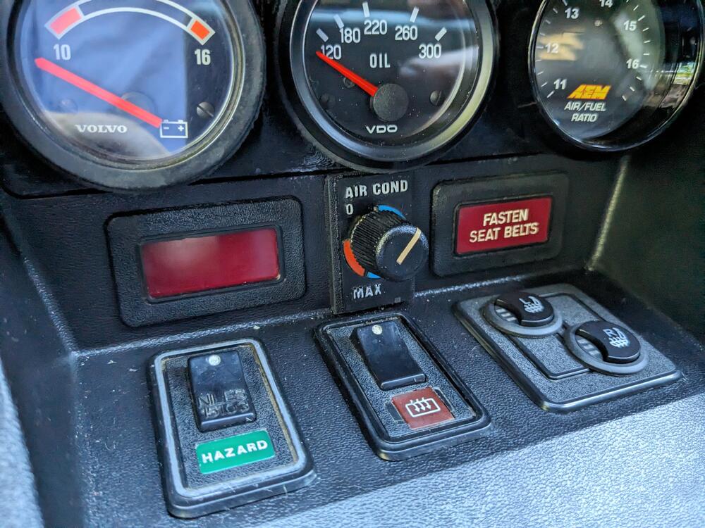
Done - had to shorten the 'nut' to 12mm for it snug in place.
-
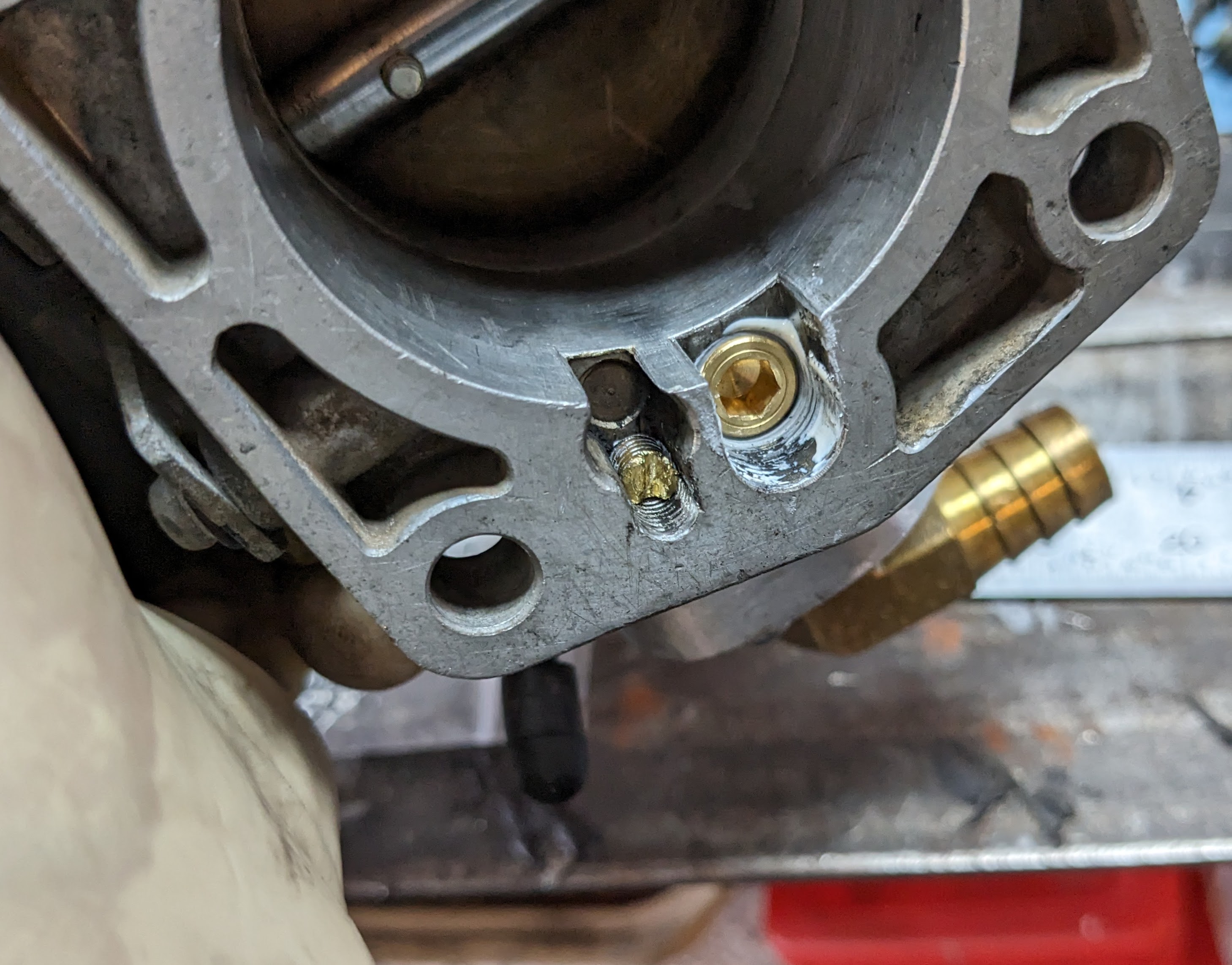
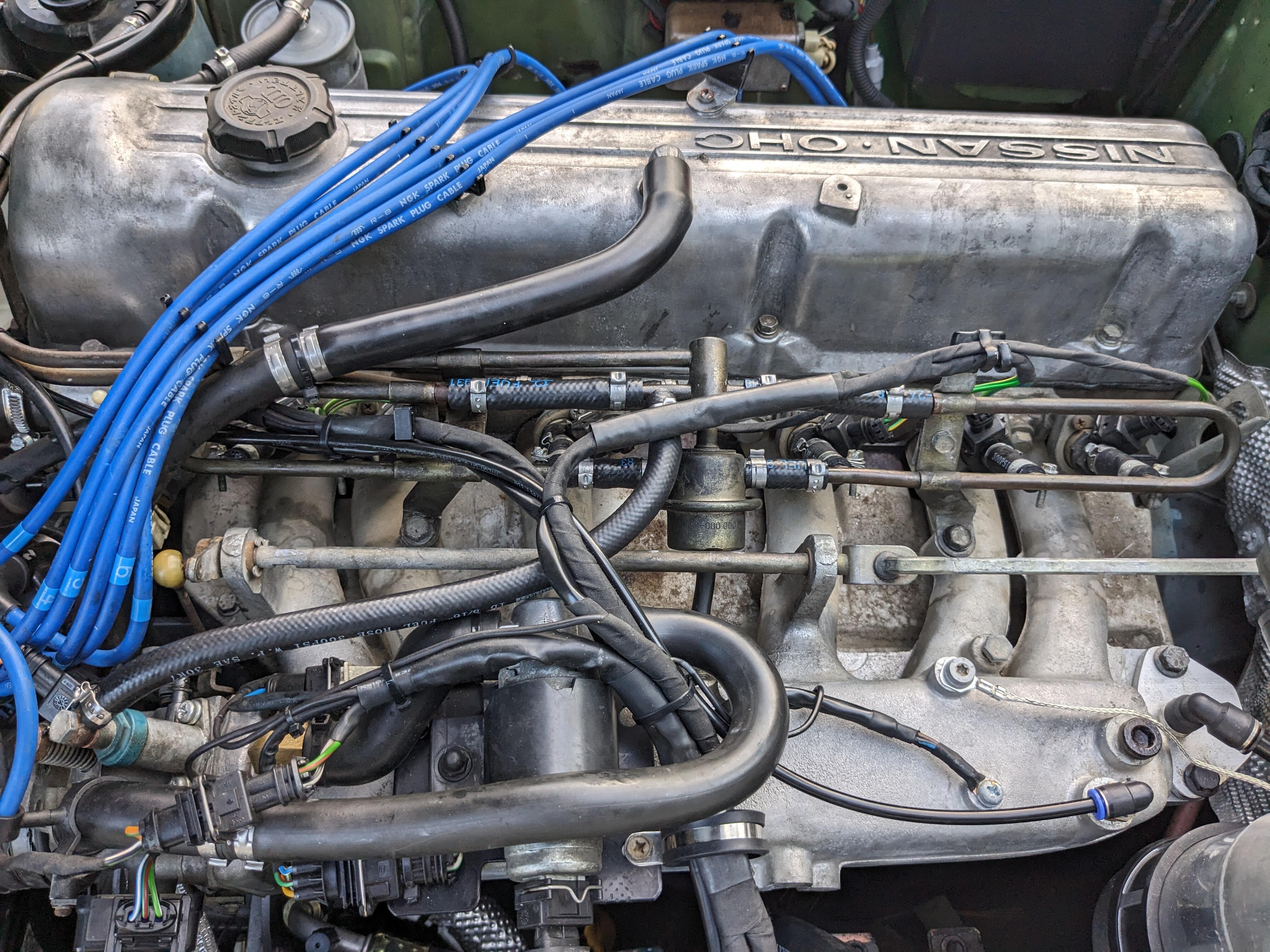
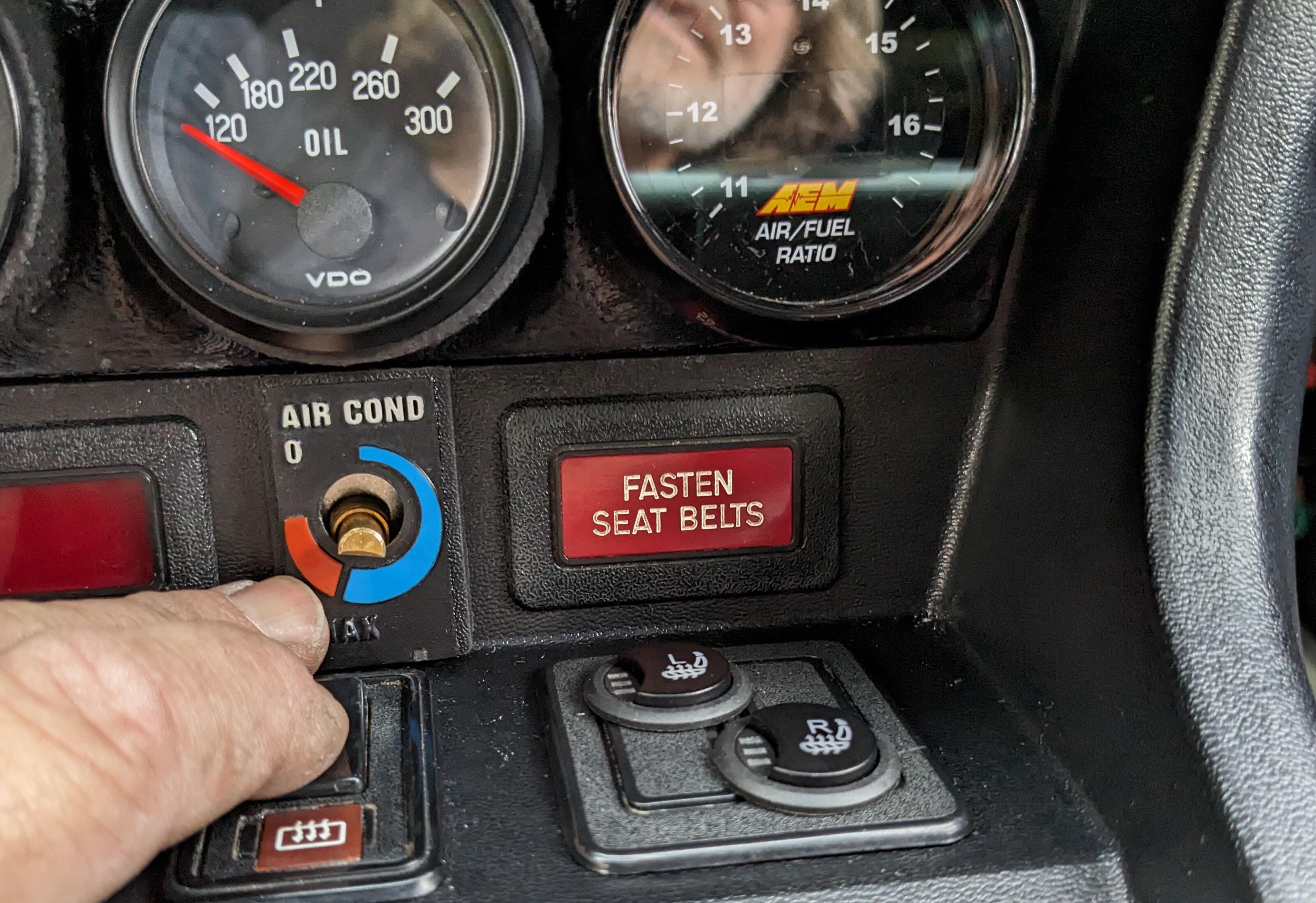
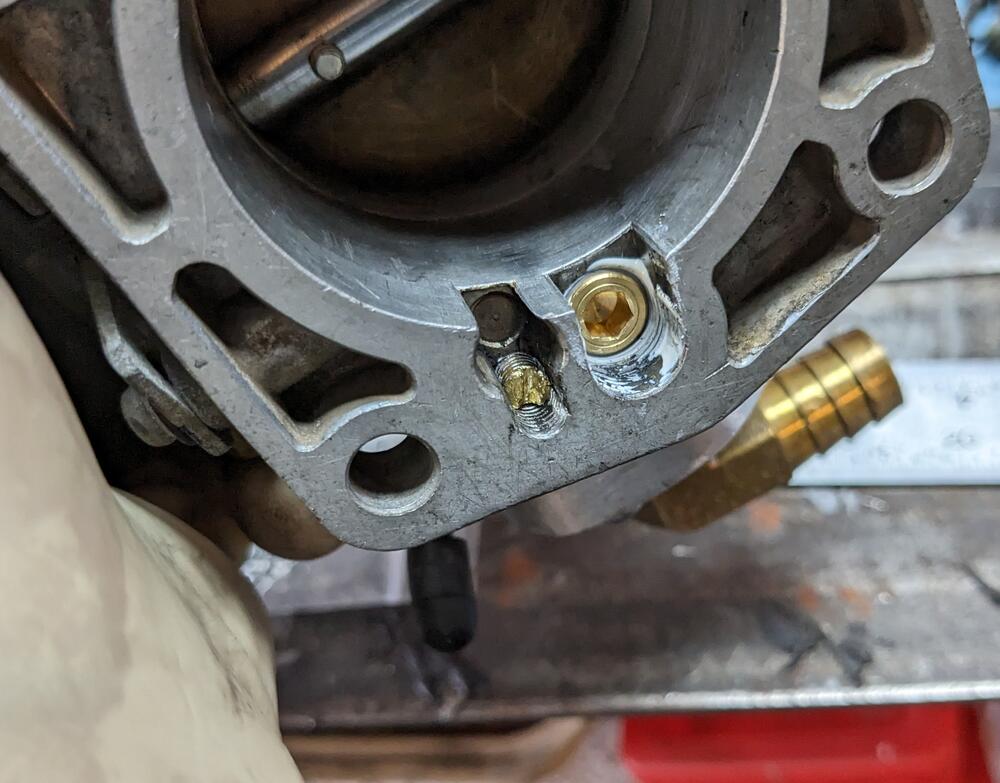
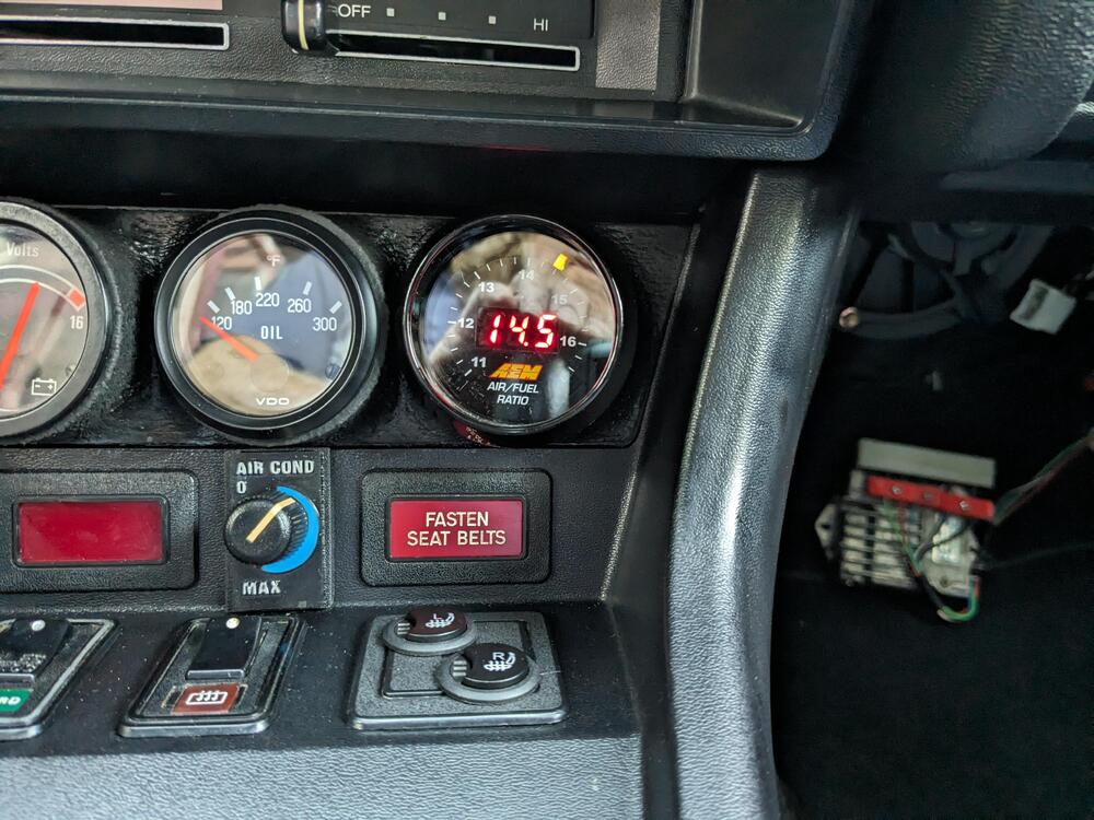
I did both openings 1/8" NPT & M5x1 Fixed the running issues! https://youtu.be/pvHhBw-u9Ro First I checked the ECT (cold, 70ºF) - 2160 ohms at the sensor at the ECU : 2180 ohms Normal OP temp 263 ohms. Values within normal range according to Datsun chart (thanks, ZedHead) I could swap it out for a Volvo one - & make it (marginally) fatter when cold.... Might need to do that depending on how the cold starts are now. Anyway, after that I went back to thinking about what could cause the hunting. I realized that when I did the TPS trigger signal, I didn't confirm that the relay I added had diode protection to prevent interference with the stock circuitry. I simply added a diode inline from the TPS to the relay to test the operation. With that in place, the hunting at 2.5K went away. So that aspect was resolved (YAY!) (Thanks also to @Captain Obvious for questioning the off idle interaction . The system still runs lean though. I don't know if all the cleaning out of coking in the TB & clearing other passages has made it leaner. I certainly didn't feel the lean running condition before I started all the mods. I looked at the AFM adjustment, and that made no meaningful difference. Manifold vacuum at idle is good. Regulated Fuel pressure is good While I cogitated on how to address this, I added the AC switch plate and added carpet mat stays So, I decided that instead of futzing with the AFM to try & tweak the AFR's 2 whole points richer, I decided to just raise the regulated pressure to 3bar - using a Volvo regulator of course As you can see form the video above, that brought the AFR's right where they need to be. new regulated fuel pressure under vacuum. Rises to 3bar with vacuum removed. Having confirmed the pressure is consistent & vacuum works I installed a nylon feed line & quick connect in the intake. Old FPR location is bridged with new hose above it. Bay Now I know the system is fully operational, I will revise the return setup, it is overly long - didn't want to cut down the hose that had to connect to the rail return until I knew it would work. With the fueling resolved, I'll switch the HEI module back & see if I can get that aspect resolved

-
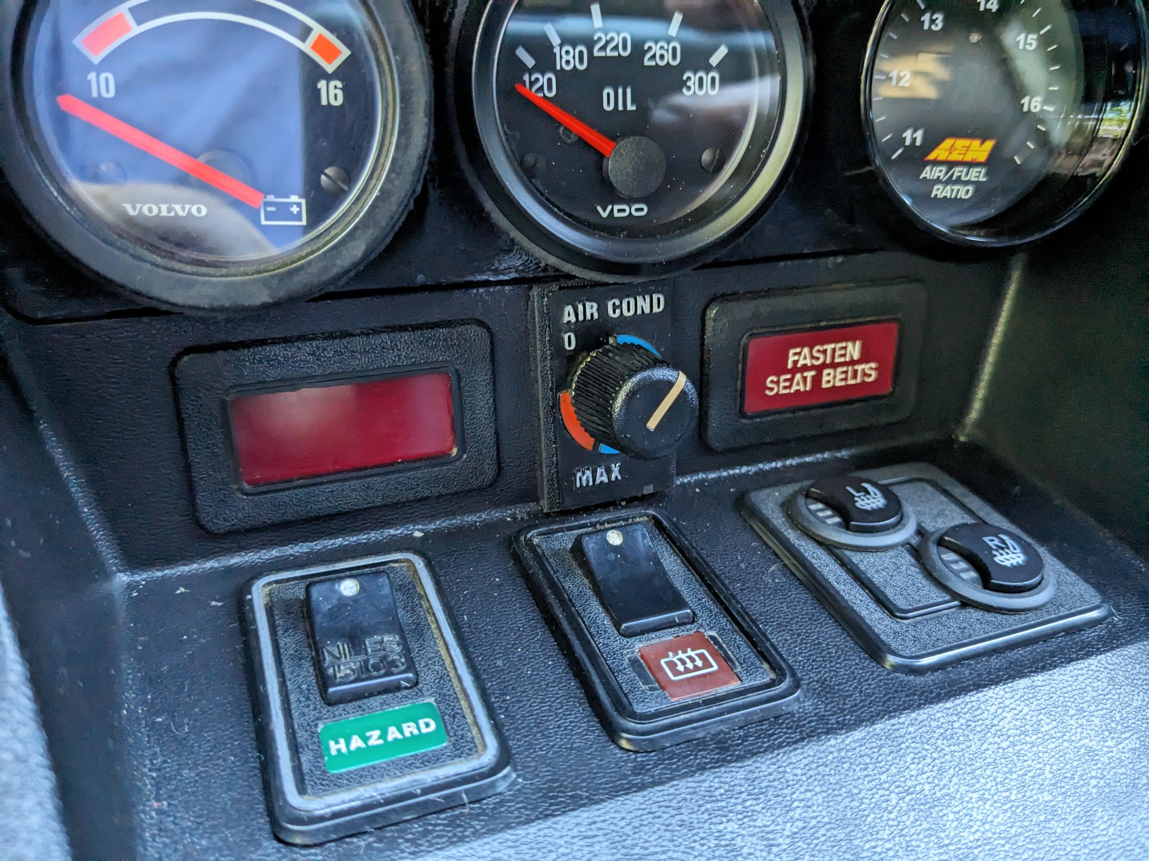
I did deal with the AC switch plate. I realized a rivnut would make the perfect shoulder nut Determined 14mm is the depth I need to seat the T/stat. Cut down a couple rivnuts until I got one that was right. Filed down the OD a touch re-threaded to 10x1, drilled out the cover plate to fit, notched the cap so I can tighten it down. should fit like this
-
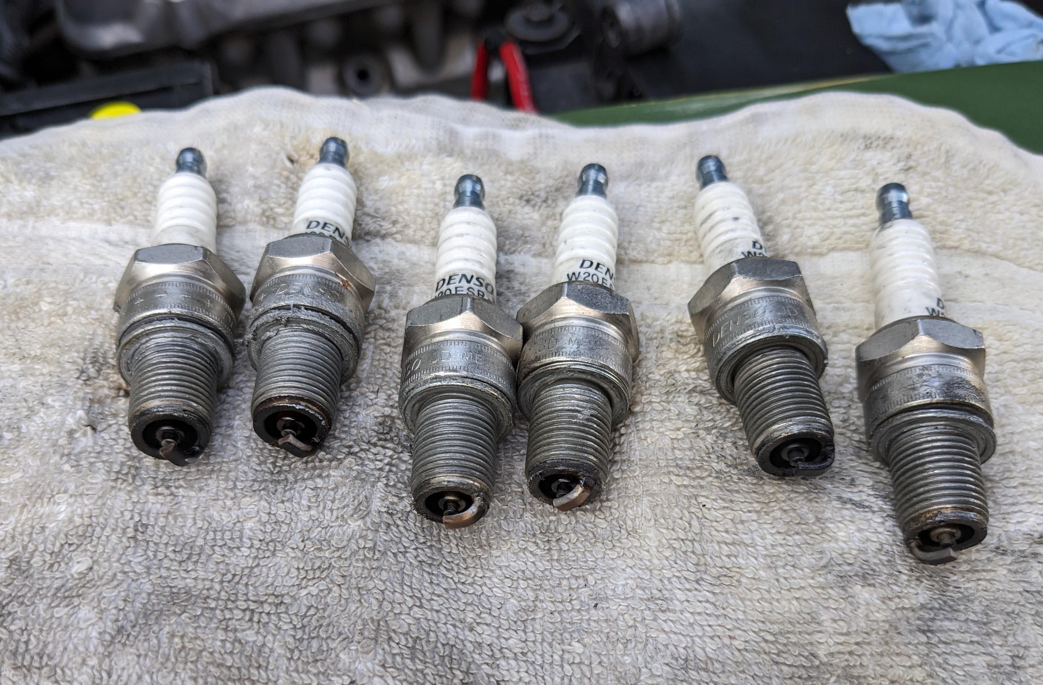
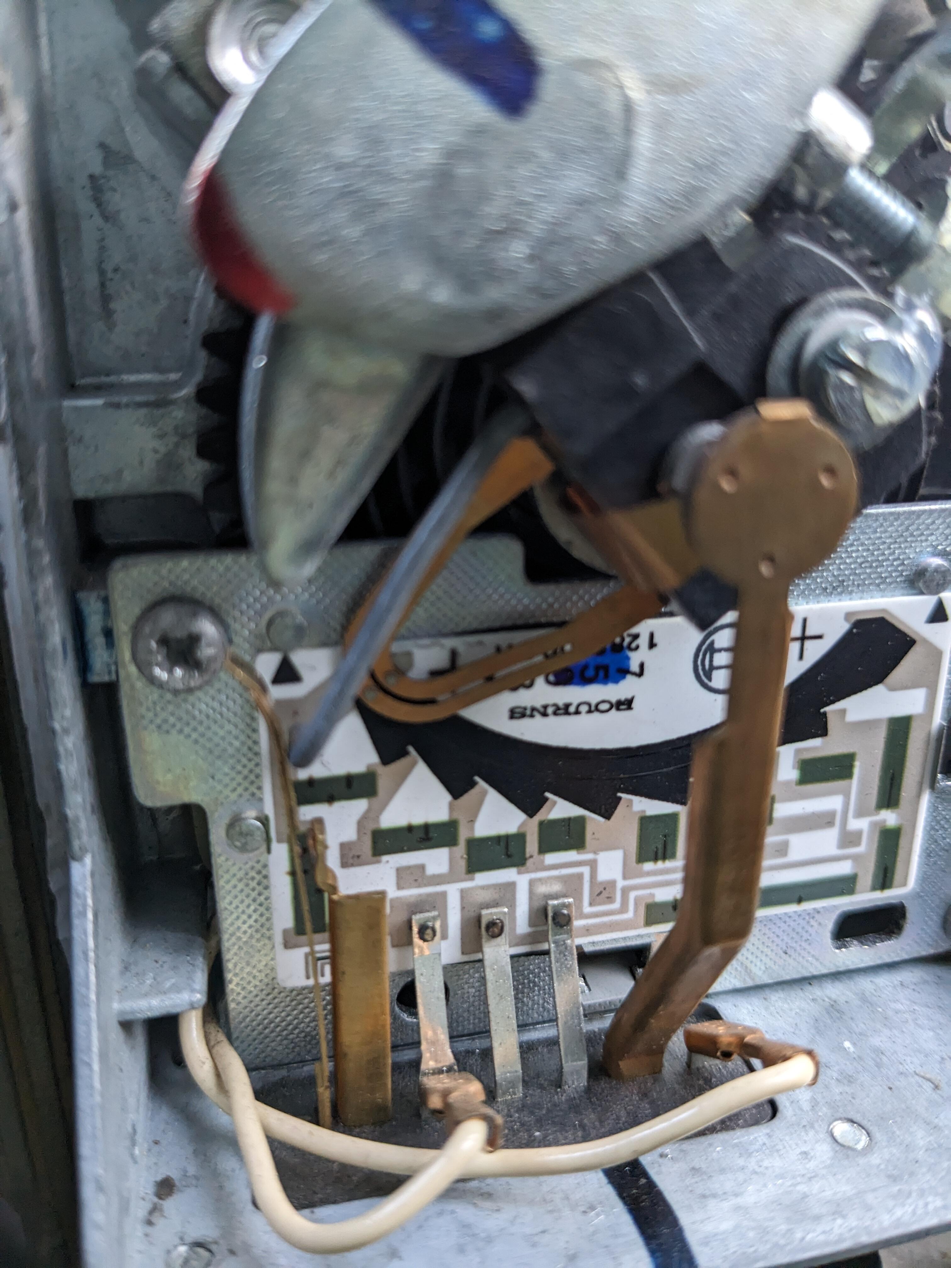
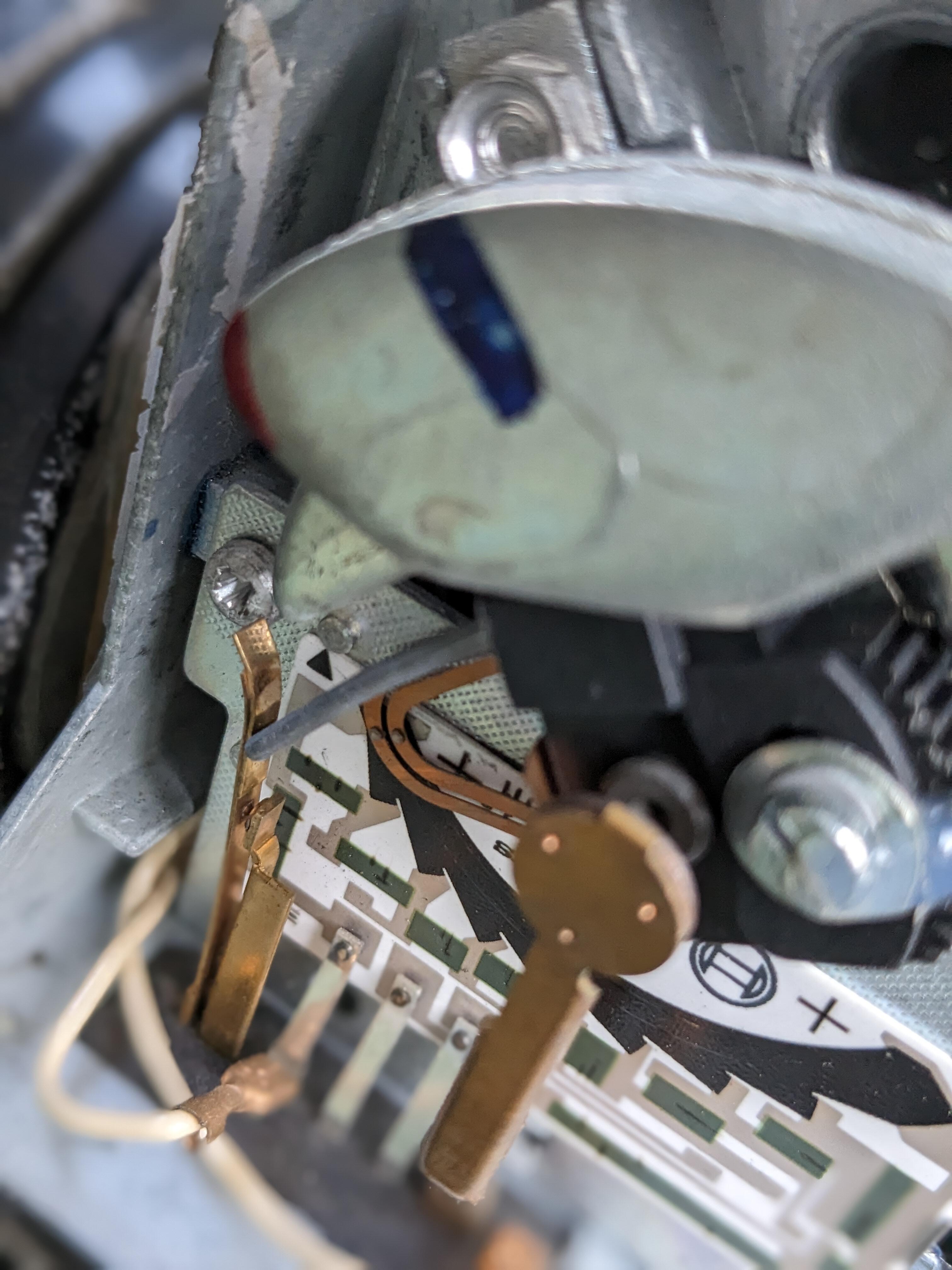
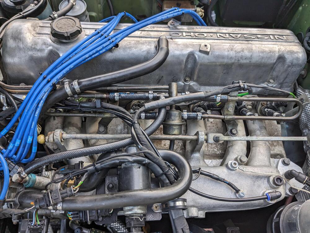
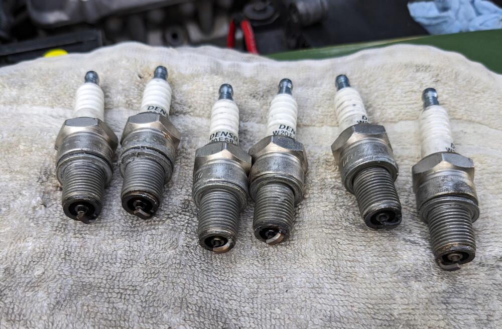
Thanks Z - good idea. I'll do that tomorrow. EDIT - I need to recheck the TPS setting as well - I had that off when I blocked off the BCDD. Need to verify idle/off idle switch point I did remove the rails & hoses, blew out the lines. No sign of debris, but at least I've ruled that out. Also pulled the plugs & checked that. They're not old, and they look pretty even The only other thing I'm wondering about, is the AFM - the cover is not fixed, and I've knocked it off several times. I'm wondering if I somehow messed up the sweep. Can't tell if it's actually making contact with the board. Does seem like a stretch, though. EDIT - looking closely at this pic on the large screen at work, I can see two track marks on the circuit.


-
I believe it, the issue is that the condition was not present prior to all the recent work, hence the need to revisit the fuel & ignition work I did. I have not touched the AFM, except to rewire the connector, but that was back in the spring & I drove the car many times after that w/o issue. I'll consider making adjustments to the AFM clocking, but not until I've ruled out any issues I may have created.
-
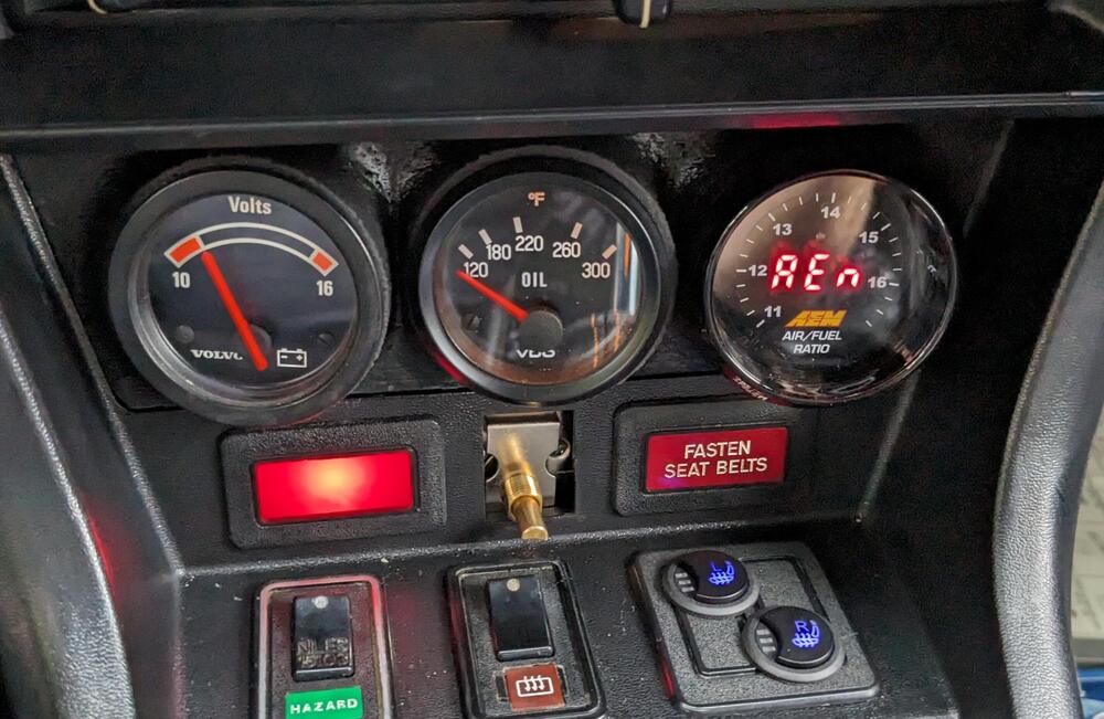
fitted Charge Lamp
-
Thanks CptO I have the front lower two secured, along with the 3 countersunk head M5 screws inside the rear tray. I guess I'll make a cross brace to unify the "wings" I don't want them potentially flapping around.
-
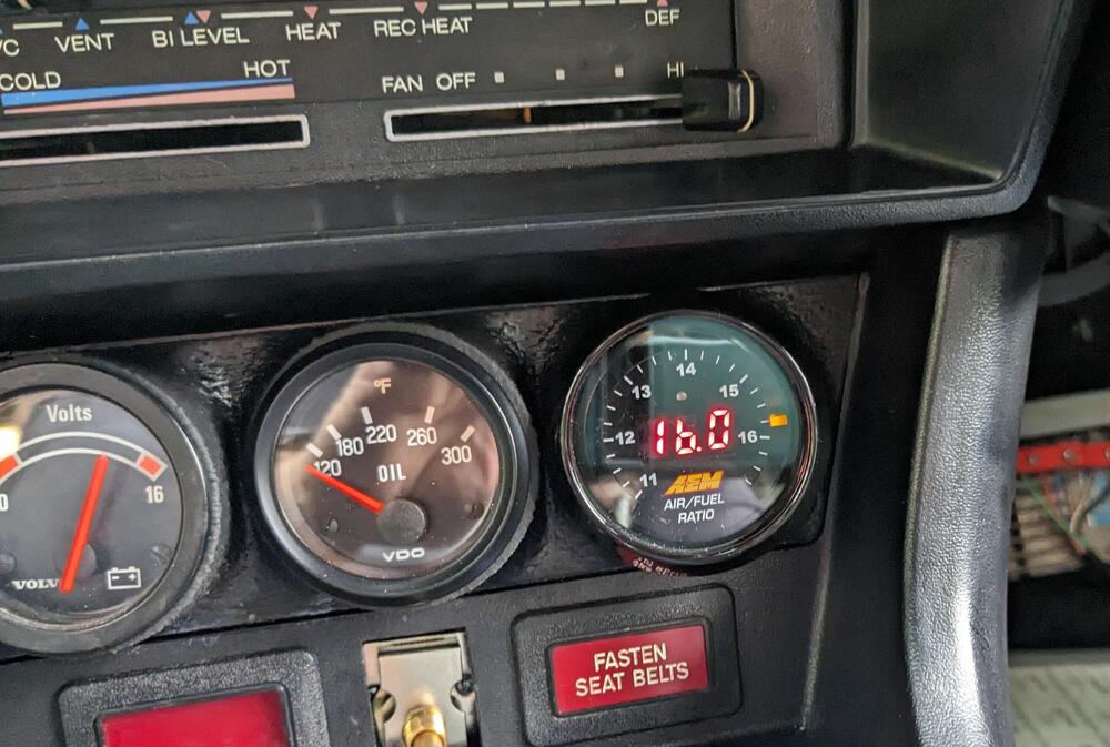
OK - so here's the problem: AFR's are way WAY to lean, even when stone cold, it started around 14 & went leaner from there. Normal op temp idle AFR's were 16.5-16.7 range. I disconnected the CIS system, and predictably it made no difference. Regulated fuel pressure is steady @ 36psi, and gets higher as vacuum decreases (when revving the motor off idle). Unplugging each injector in turn, affects the running. I'm going to pull the rail & check for any restrictions.
-
-
Found I have another (minor) issue - the T/stat can't be bolted to the console - the threaded section is too short for the depth of the console. I made a face plate using a Volvo 240 part. What I'm going to need is a shouldered nut, basically a top hat.
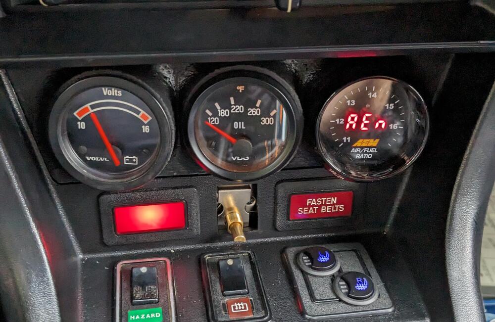

-
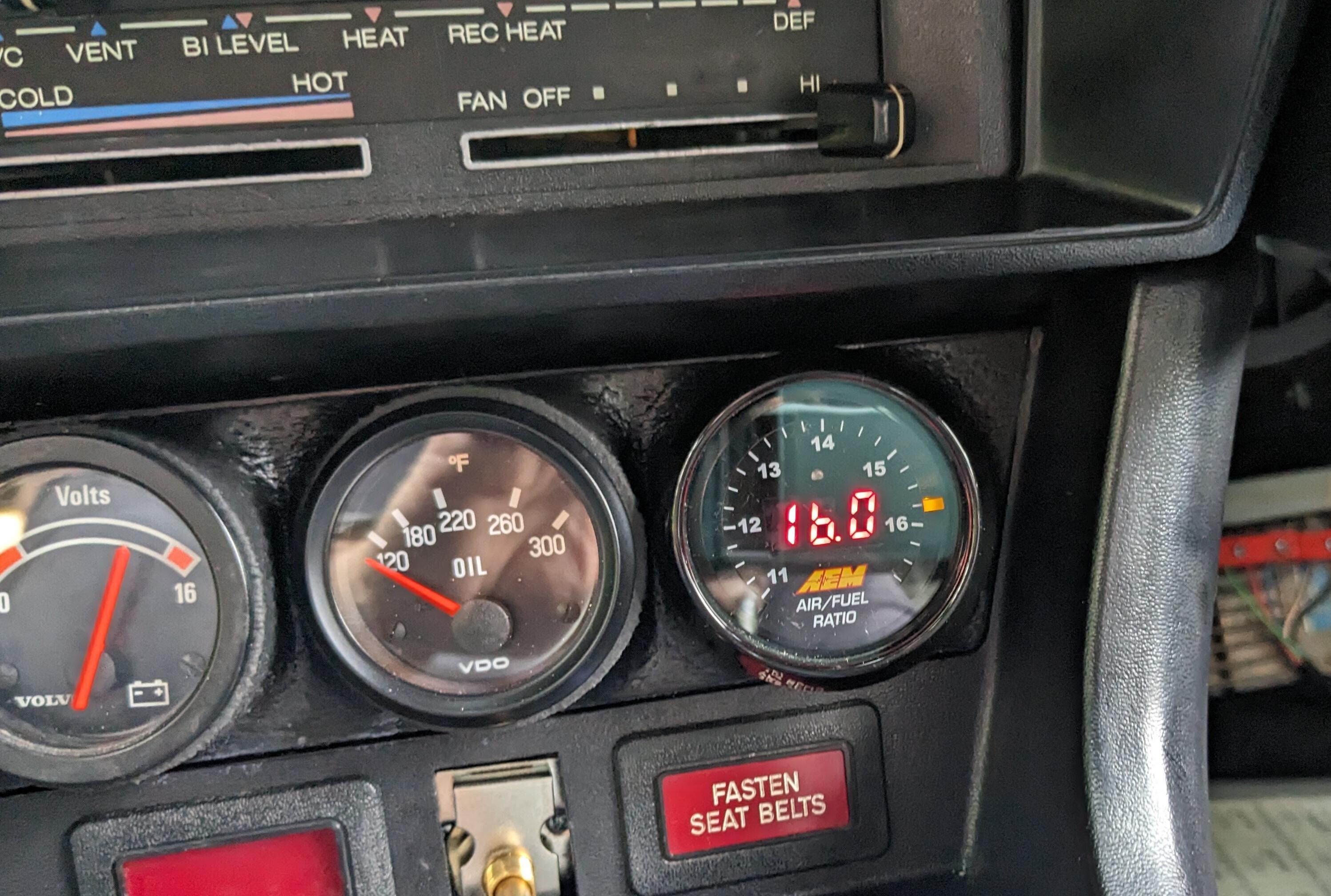
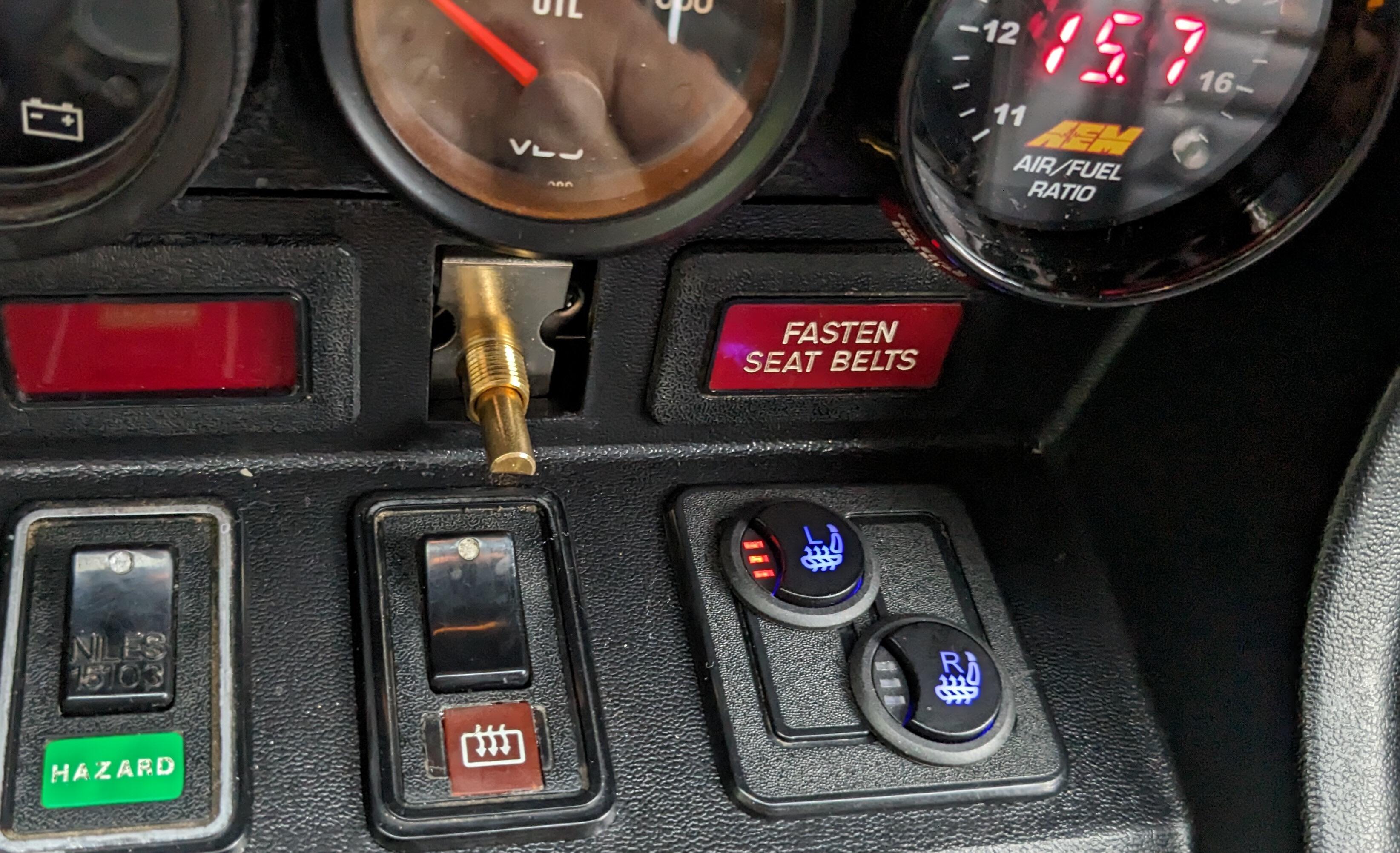
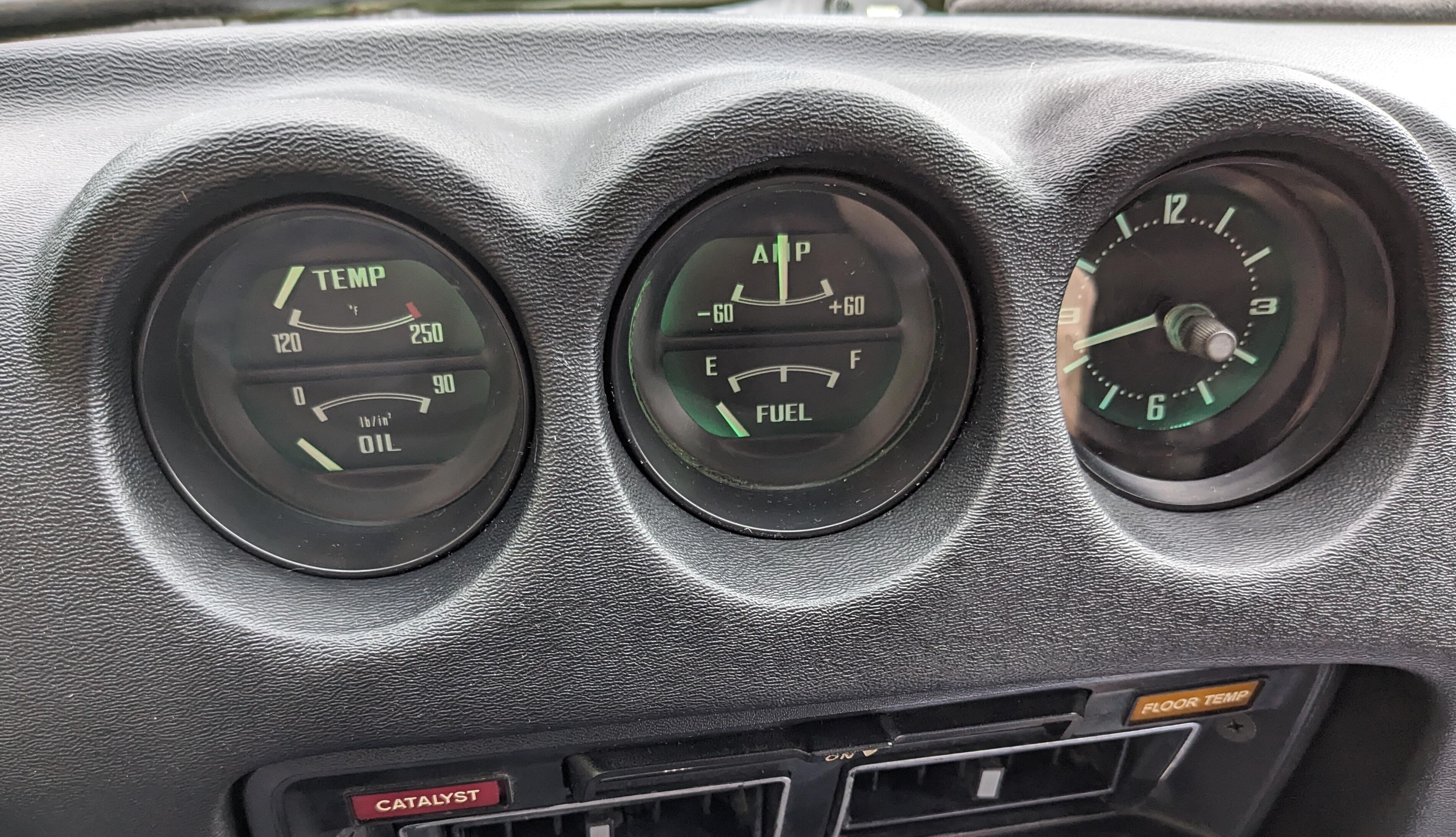
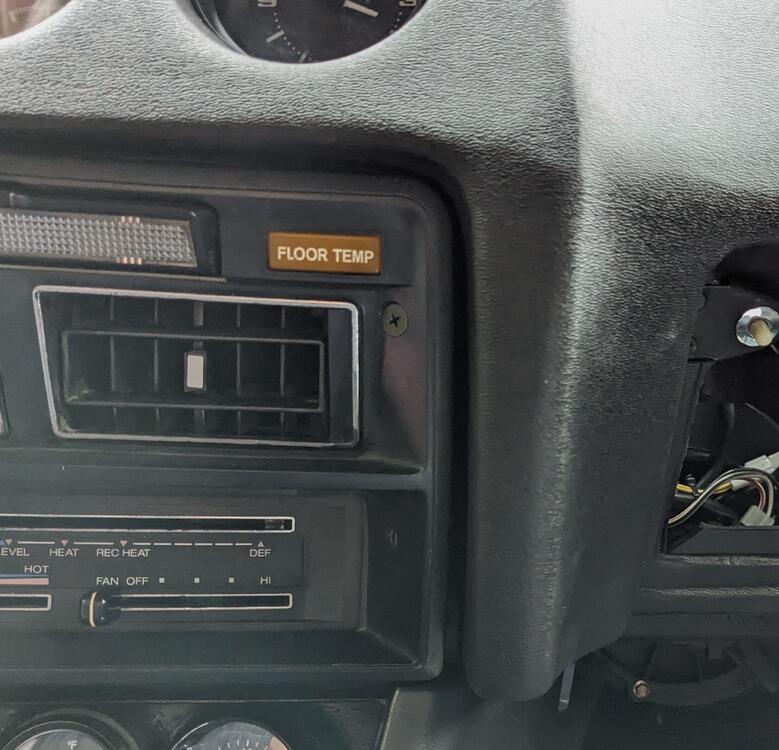
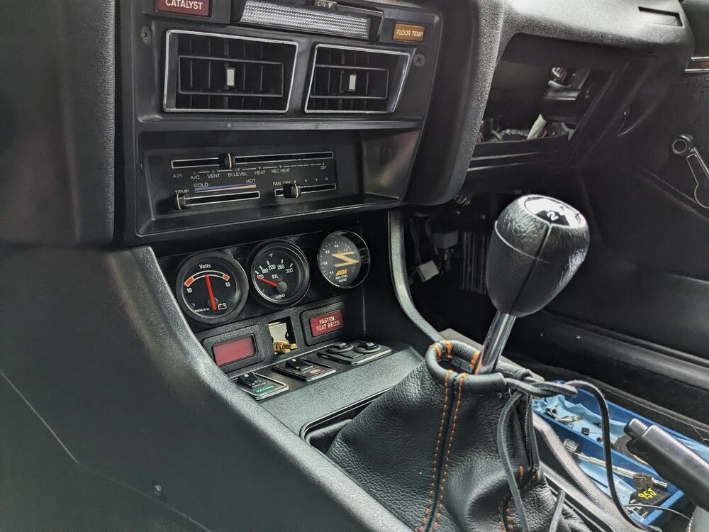
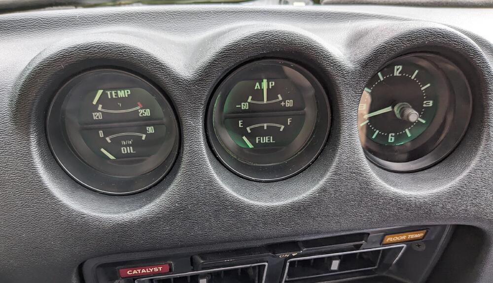
Center opening gap difference Left to Right Didn't notice with the original center console whether the dash aligned with the uprights. or if its staggered like this EDIT - forgot to add pics with the LED bulbs illuminated AS SteveJ mentioned somewhere the Tach lighting has reversed polarity sockets, so I use conventional bulbs there. Not quite as bright.



-
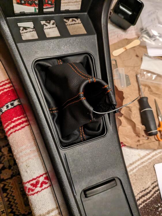
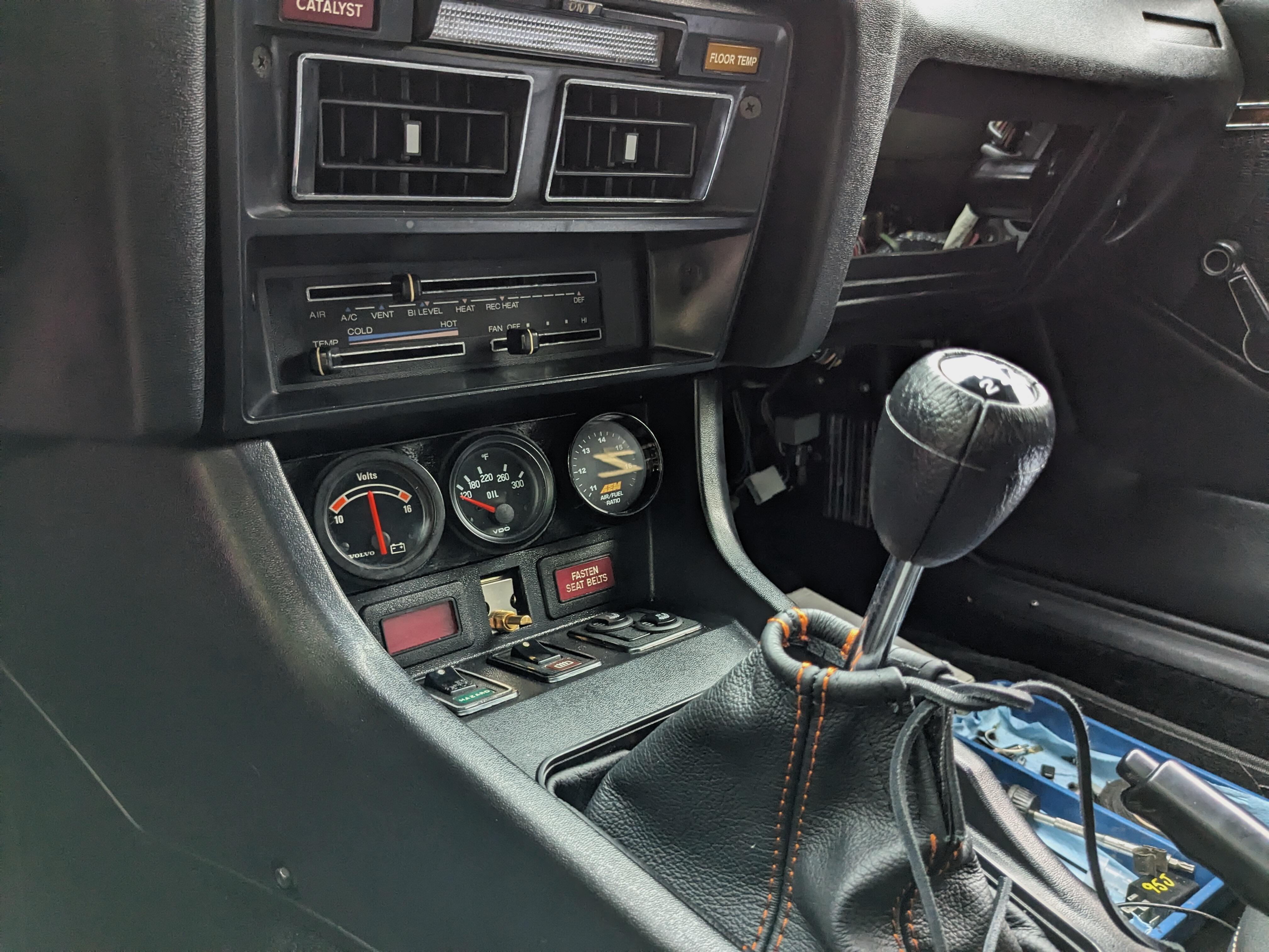
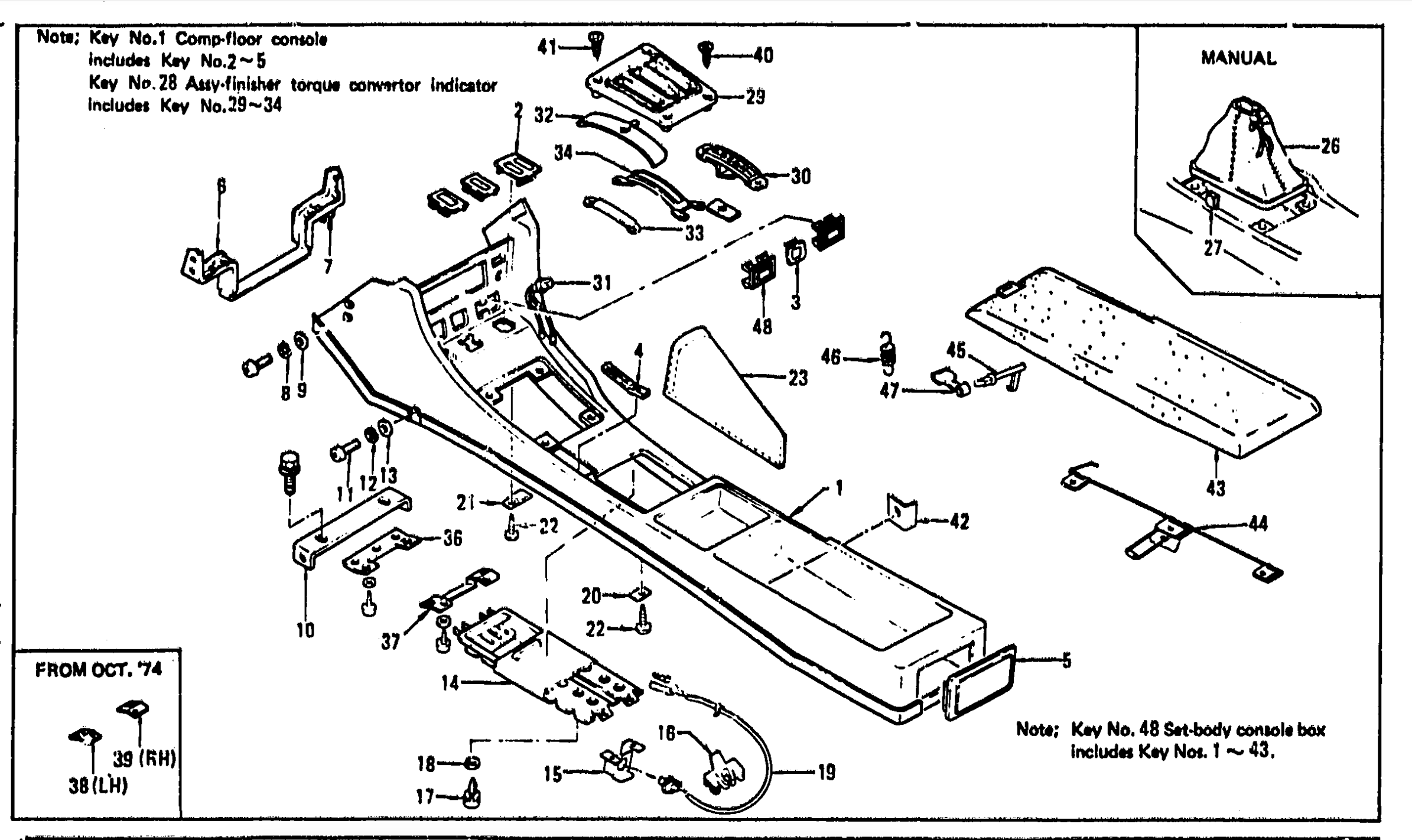
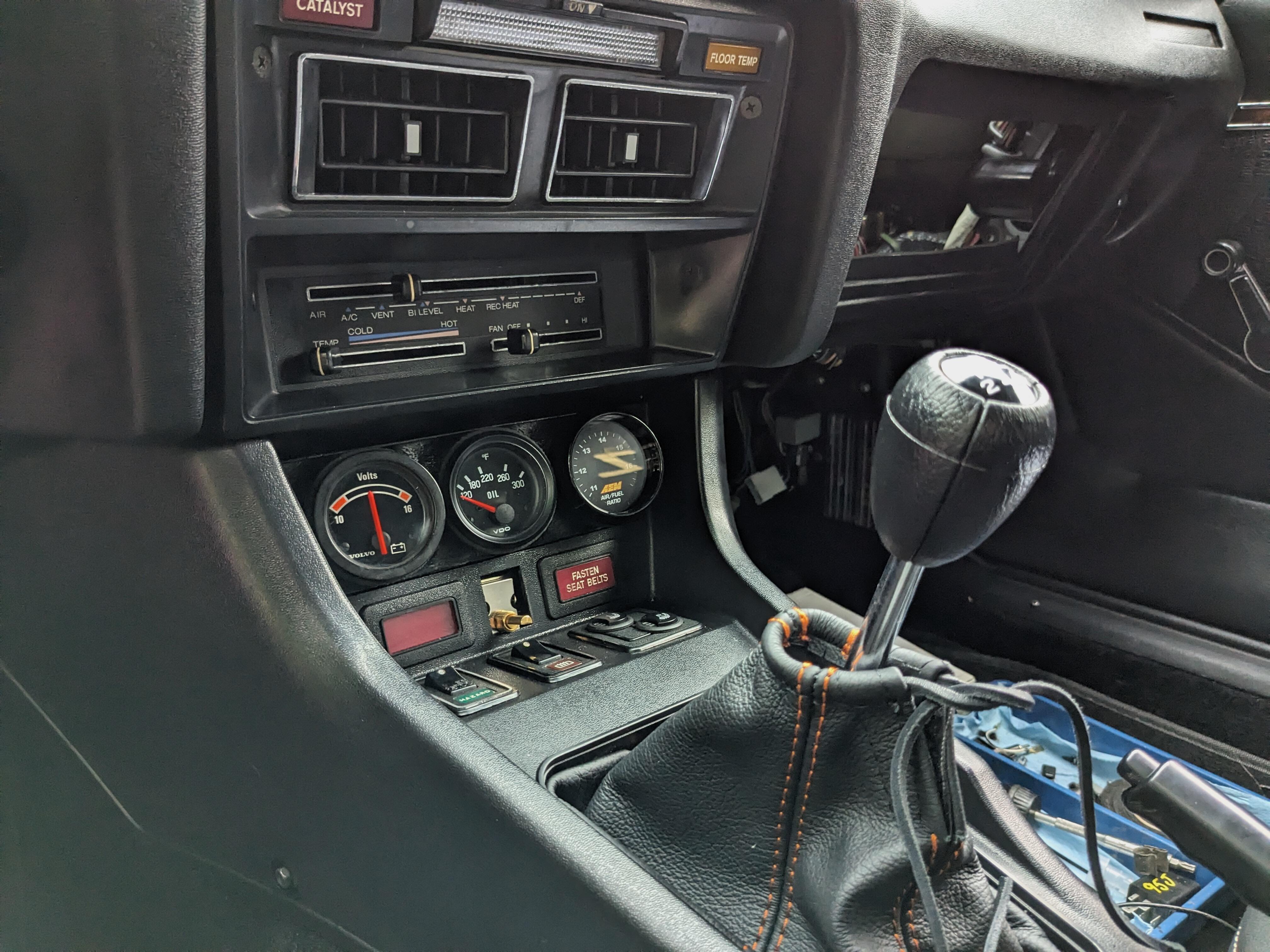
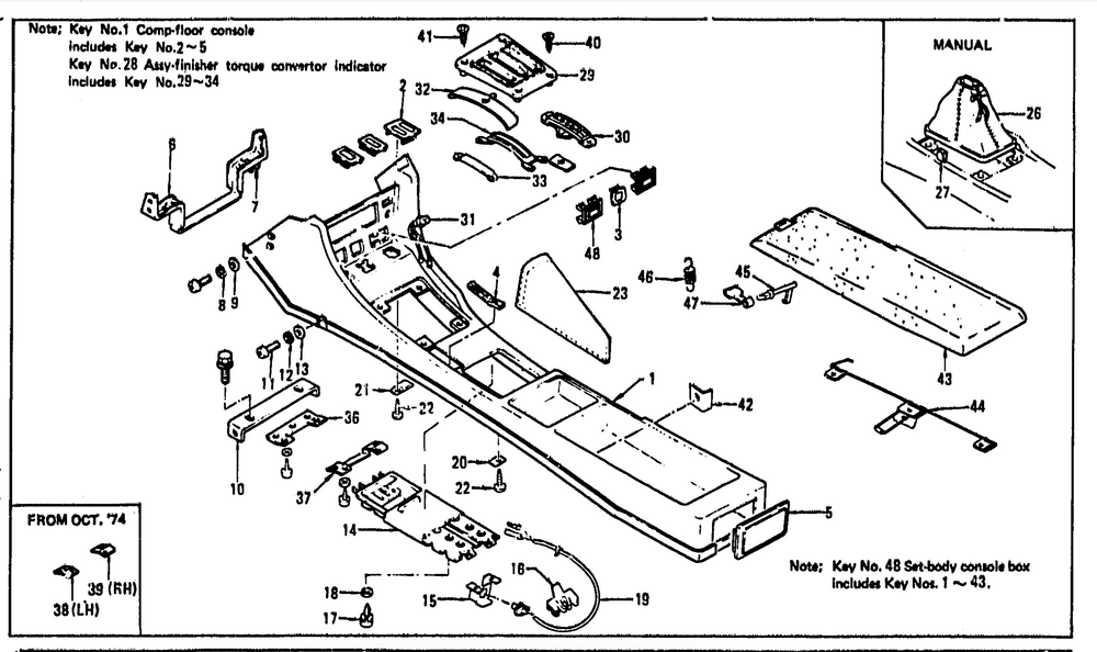
So, I installed the console today - and I don't have anything for the forward upper portion to attach to. I had a bracket that I thought was it - but it was just the tie plate that is secured with 2 M5 screws at the base of the center opening, that the HVAC control sits on. I can't figure out from the part catalog what would even constitute the support, unless it's the 'Radio Bracket" 96915 - N4200, #6 in the diagram Not really happy with the shifter boot fit - the opening is way too large for the stock shaft. Too much work to cut & resew.
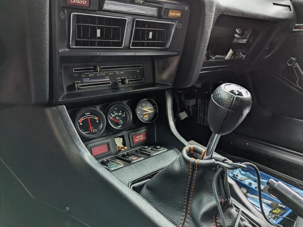
-
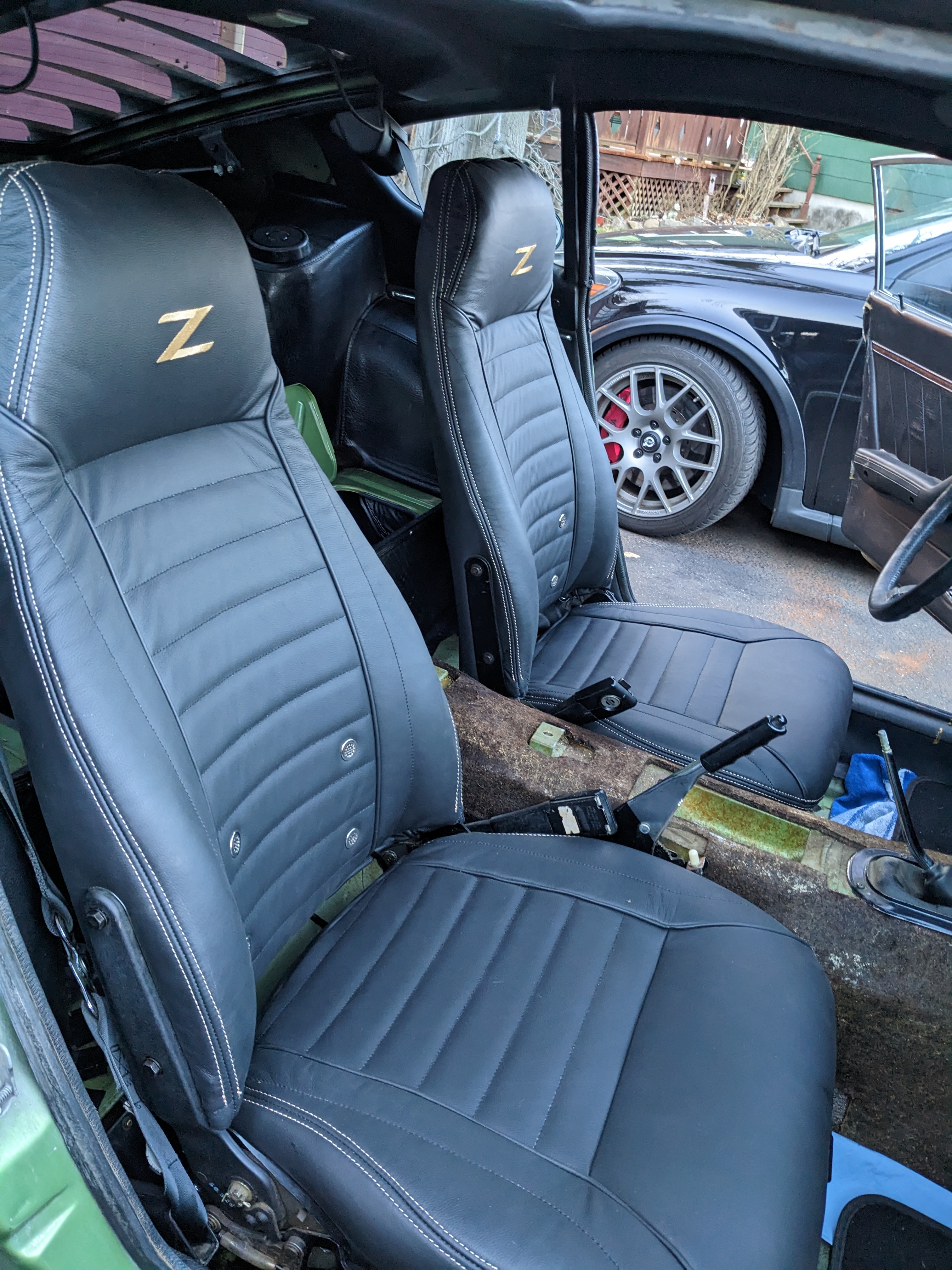
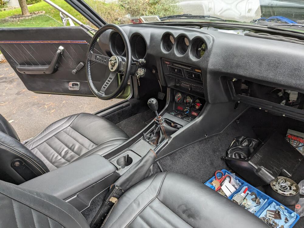
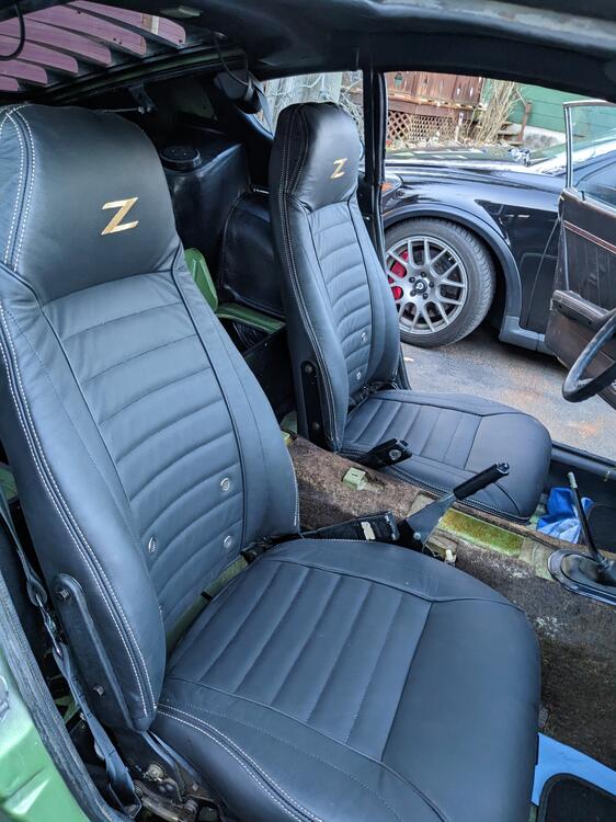
It's Leaf Green with regular black interior - I didn't get custom stitching when got the seat upholstery
-
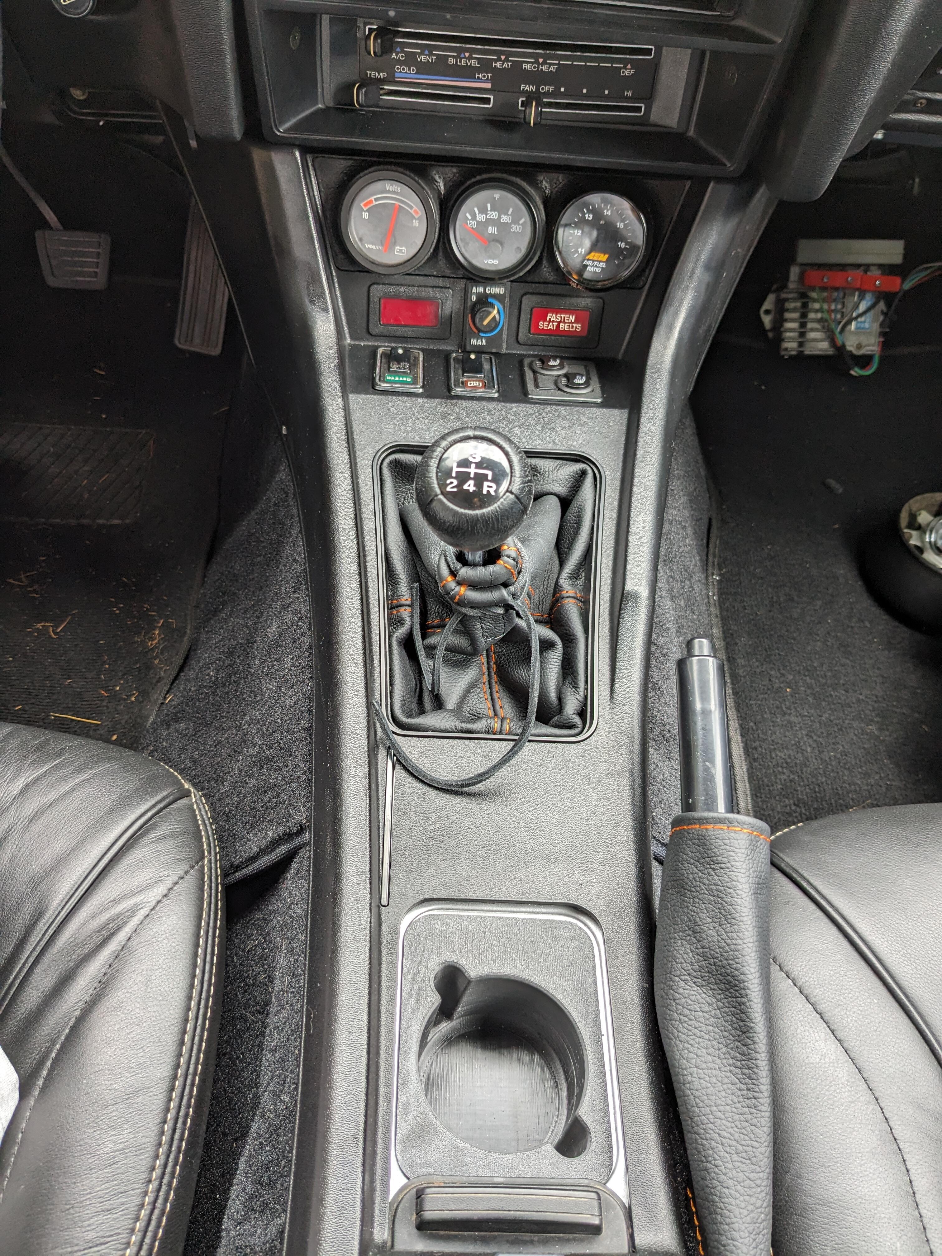
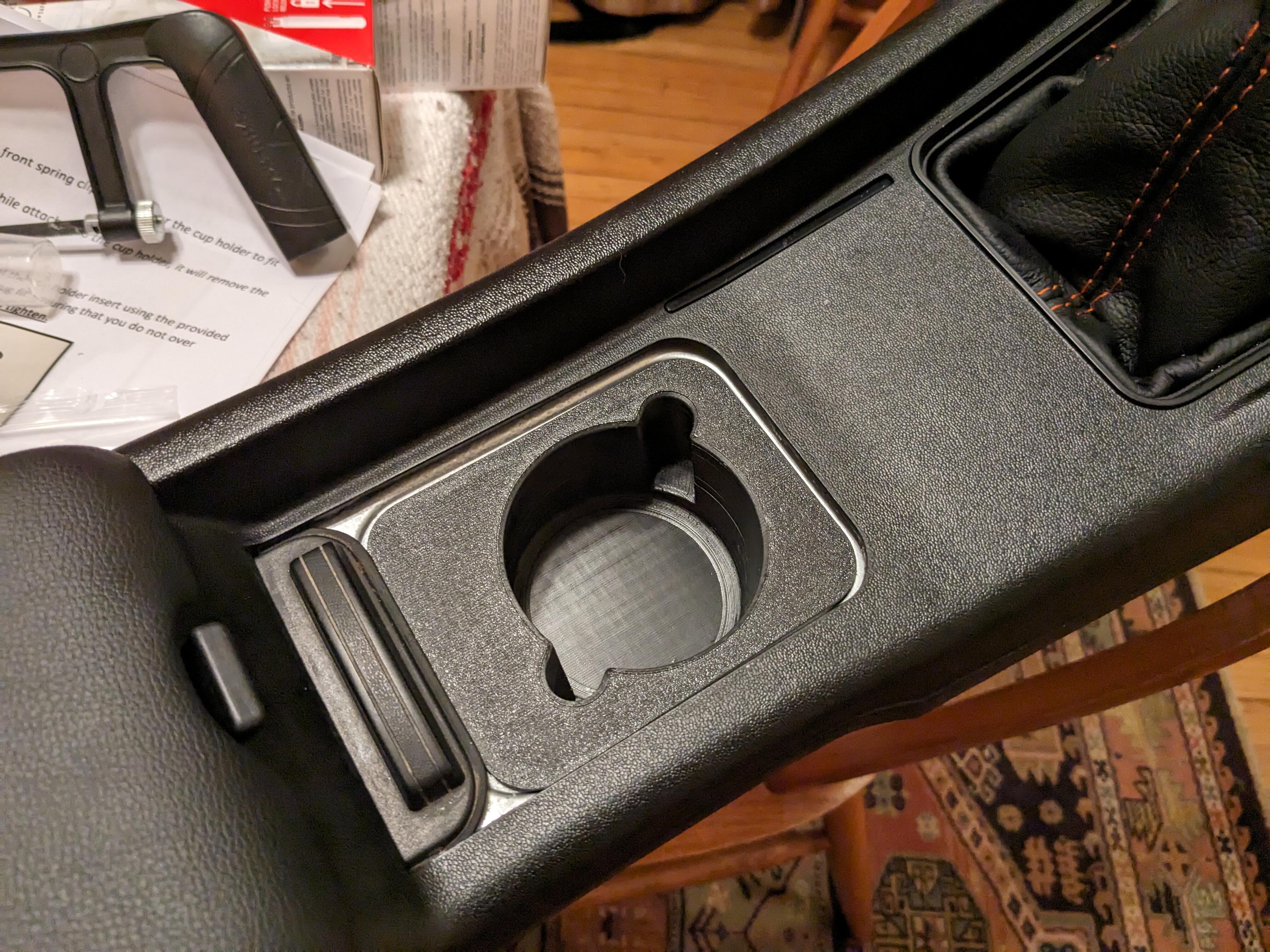
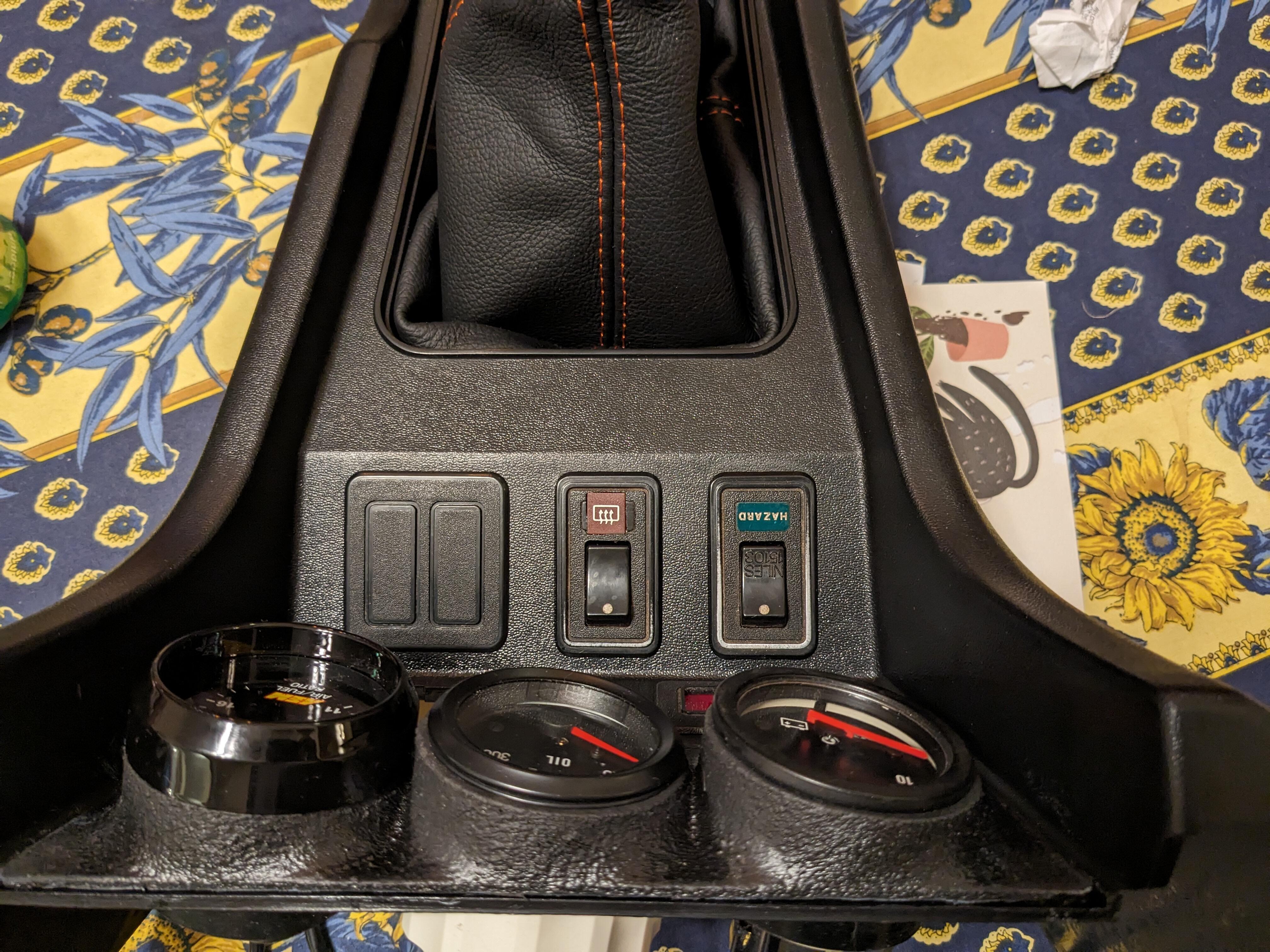
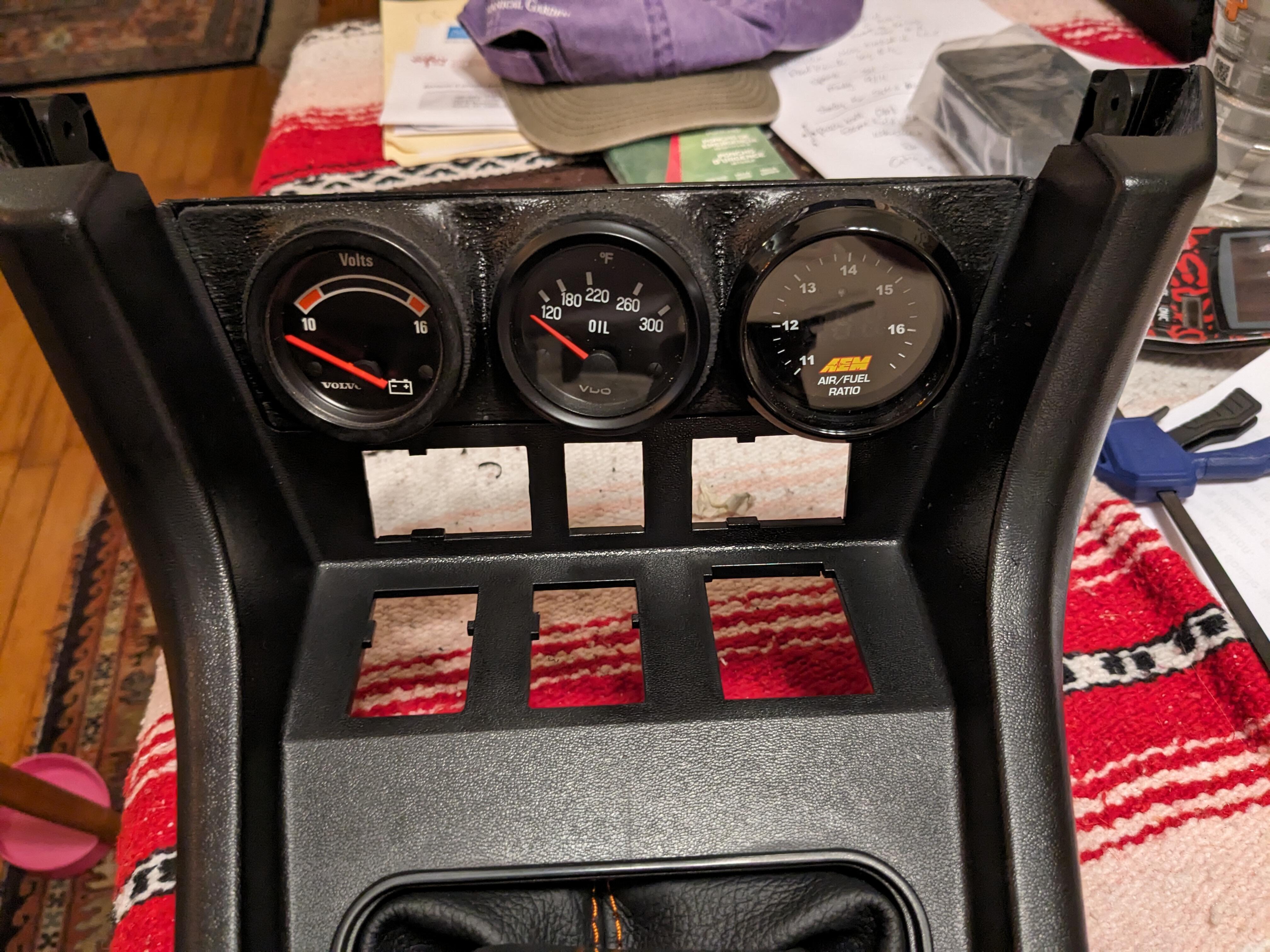
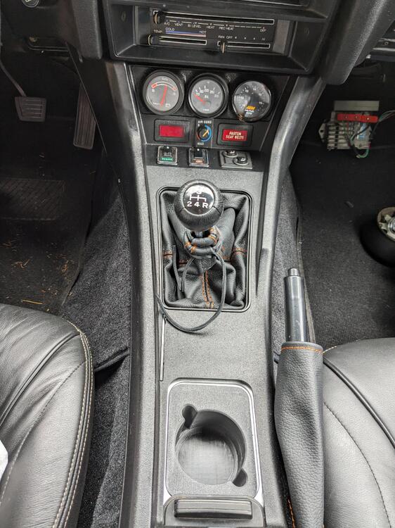
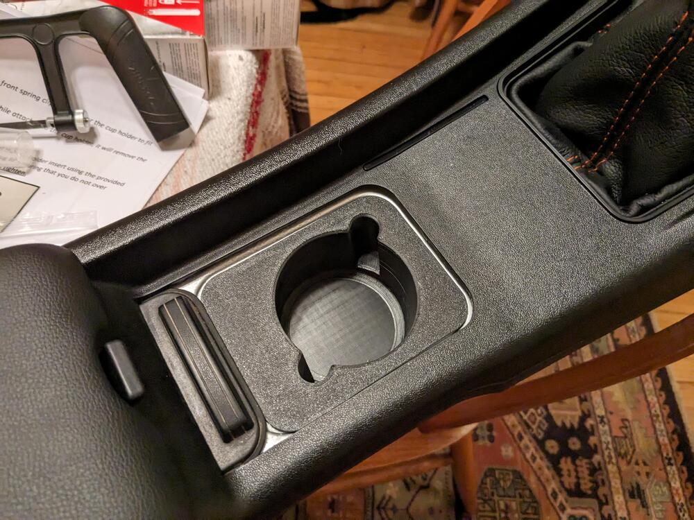
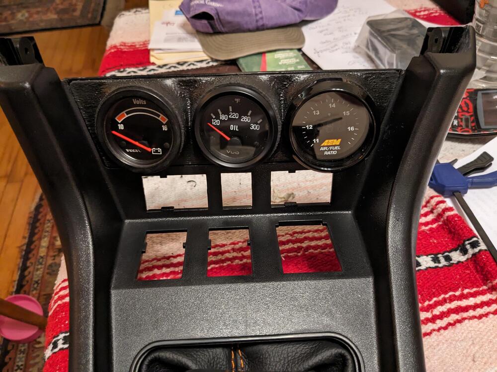
Also added a MilkFab 3 gauge pod and a cupholder to mine

-
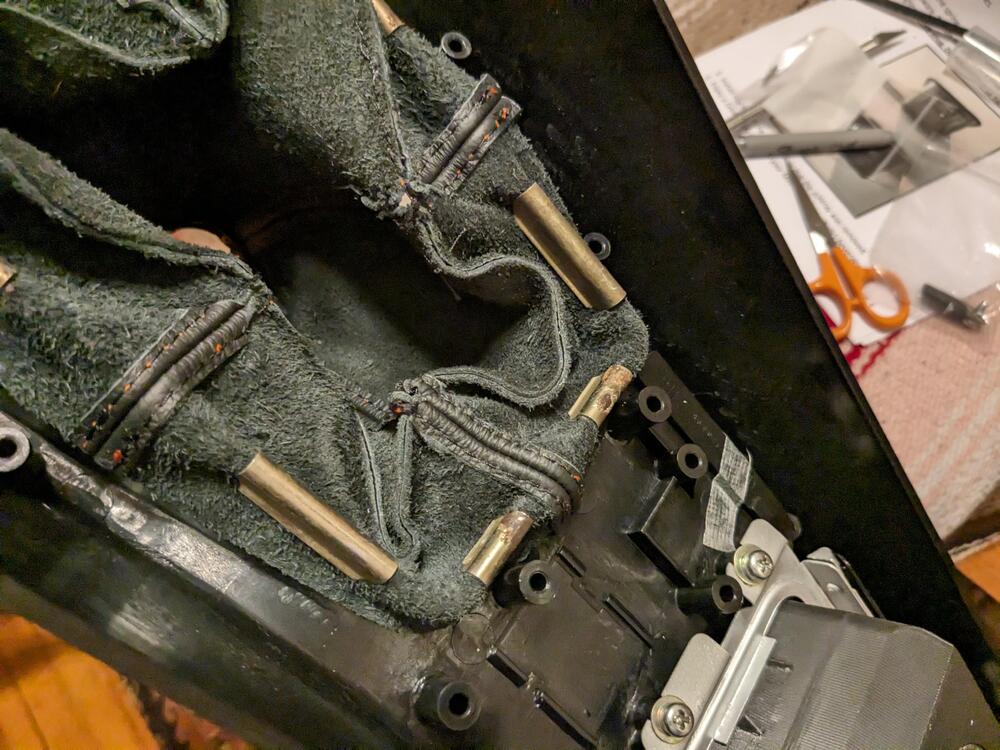
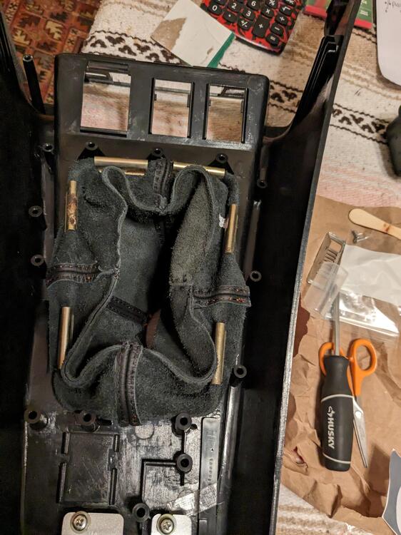
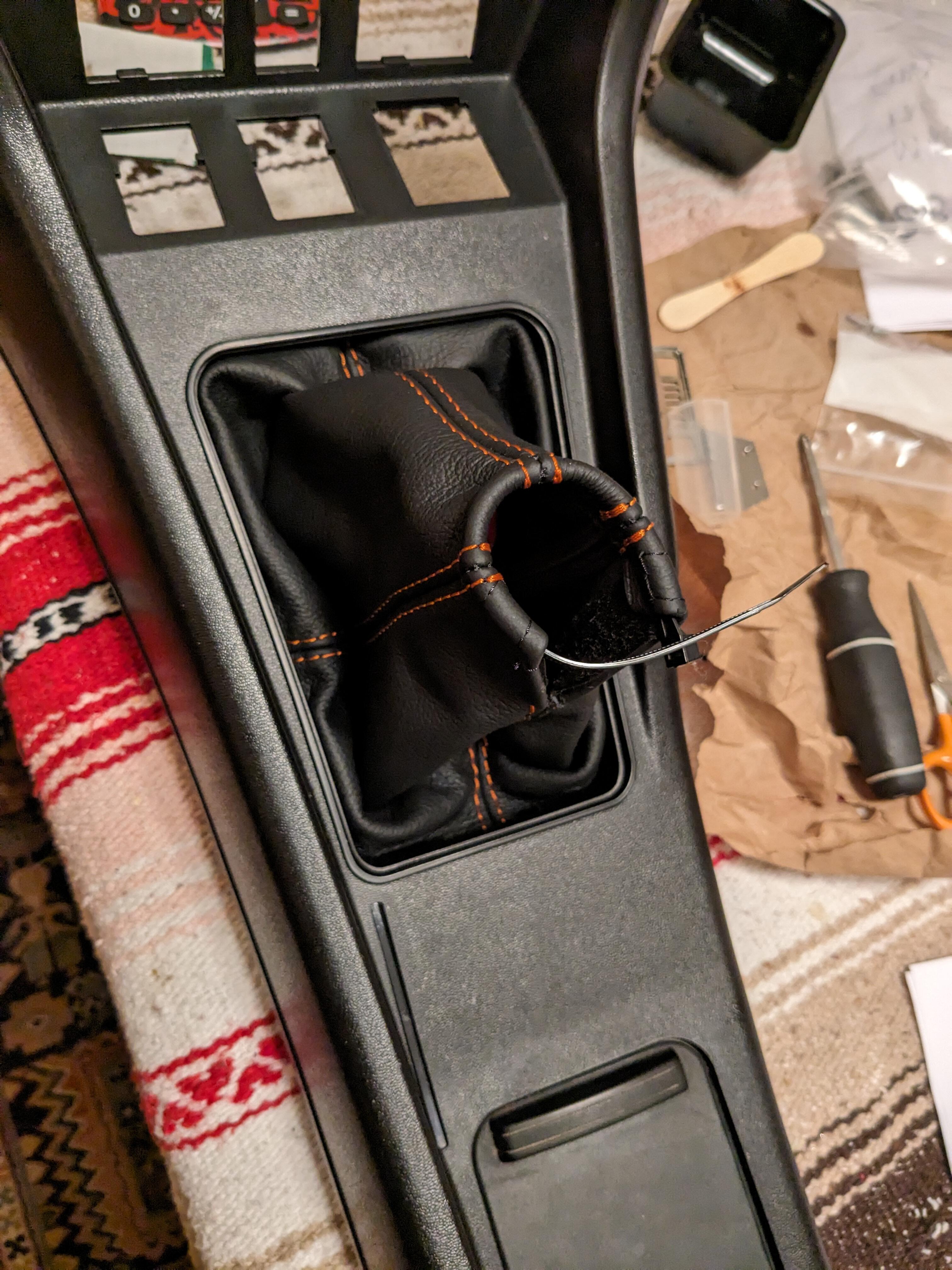
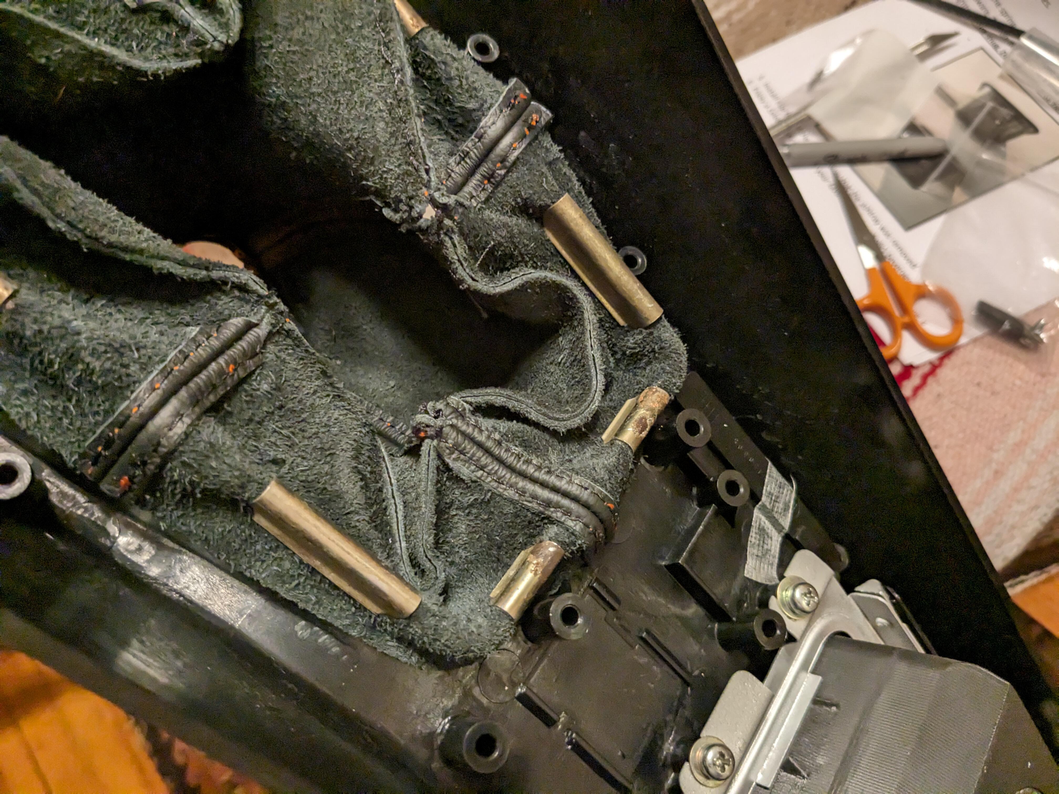
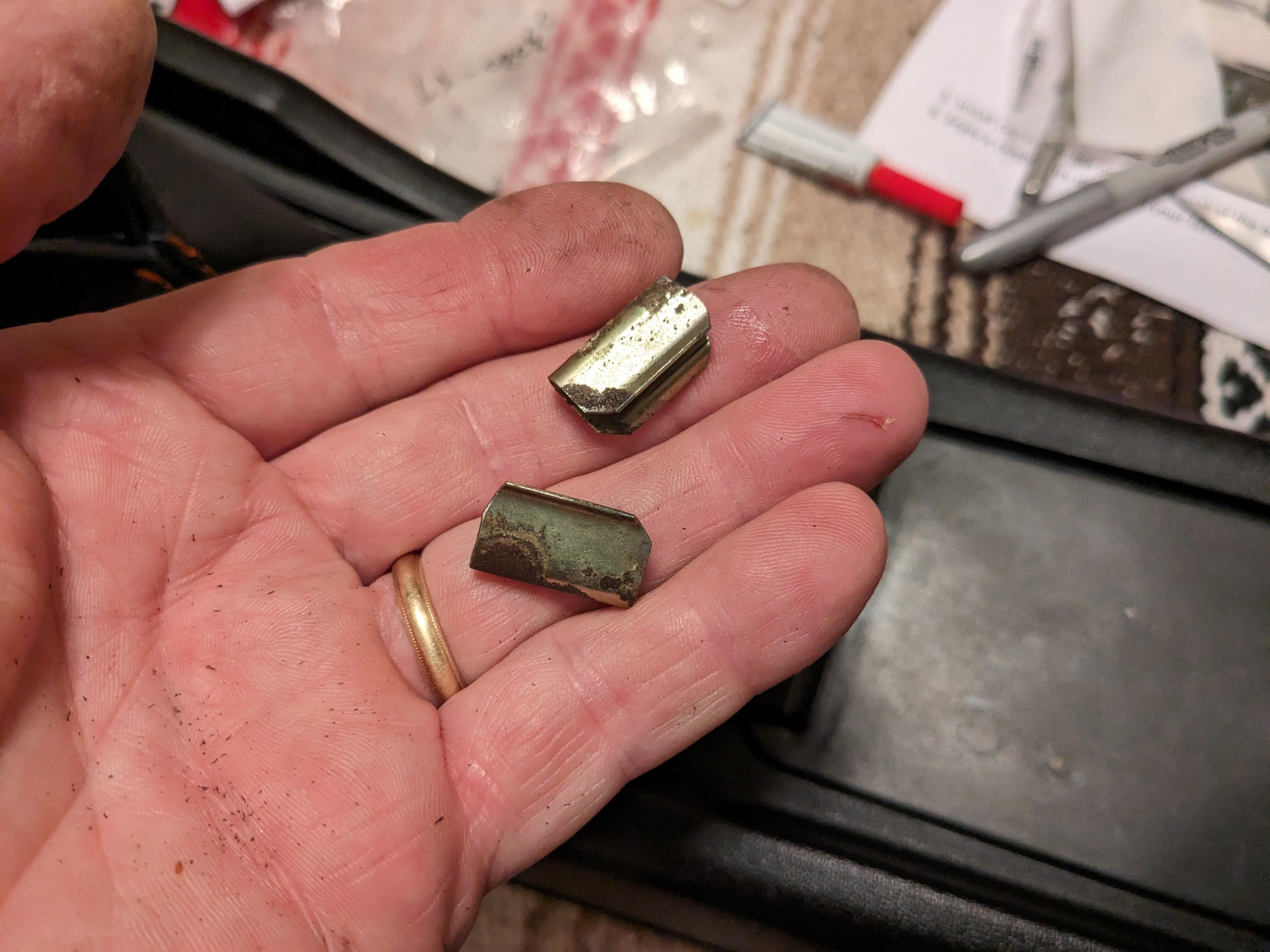
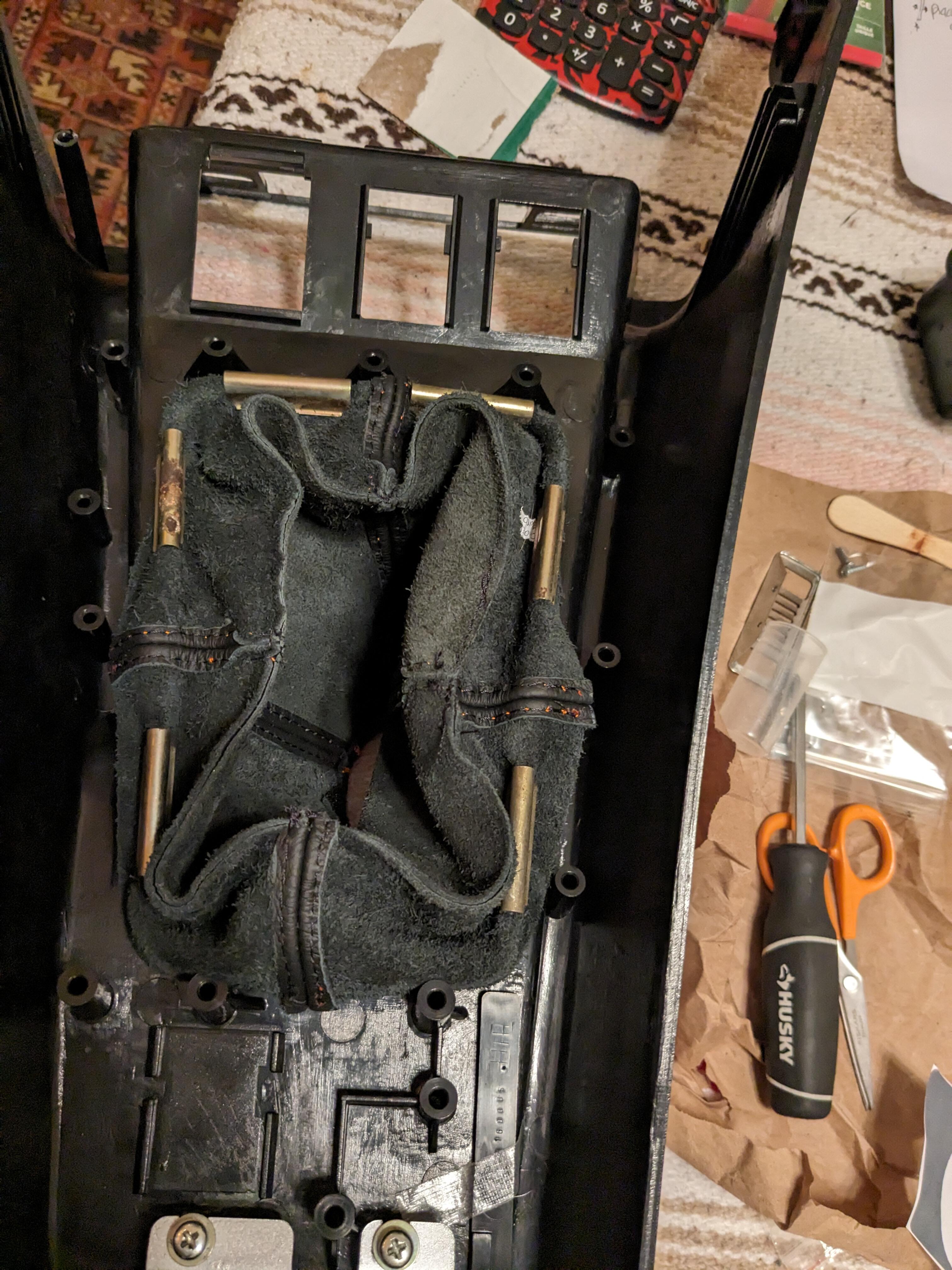
It's a shame that so many ppl don't think to add pics that would clarify so much. I installed a leather boot in mine, getting ready to put the console back had to cut a clip for the rear, the full width don't fit the aftermarket leather boot