HusseinHolland
Community Member
-
Joined
-
Last visited
Everything posted by HusseinHolland
-
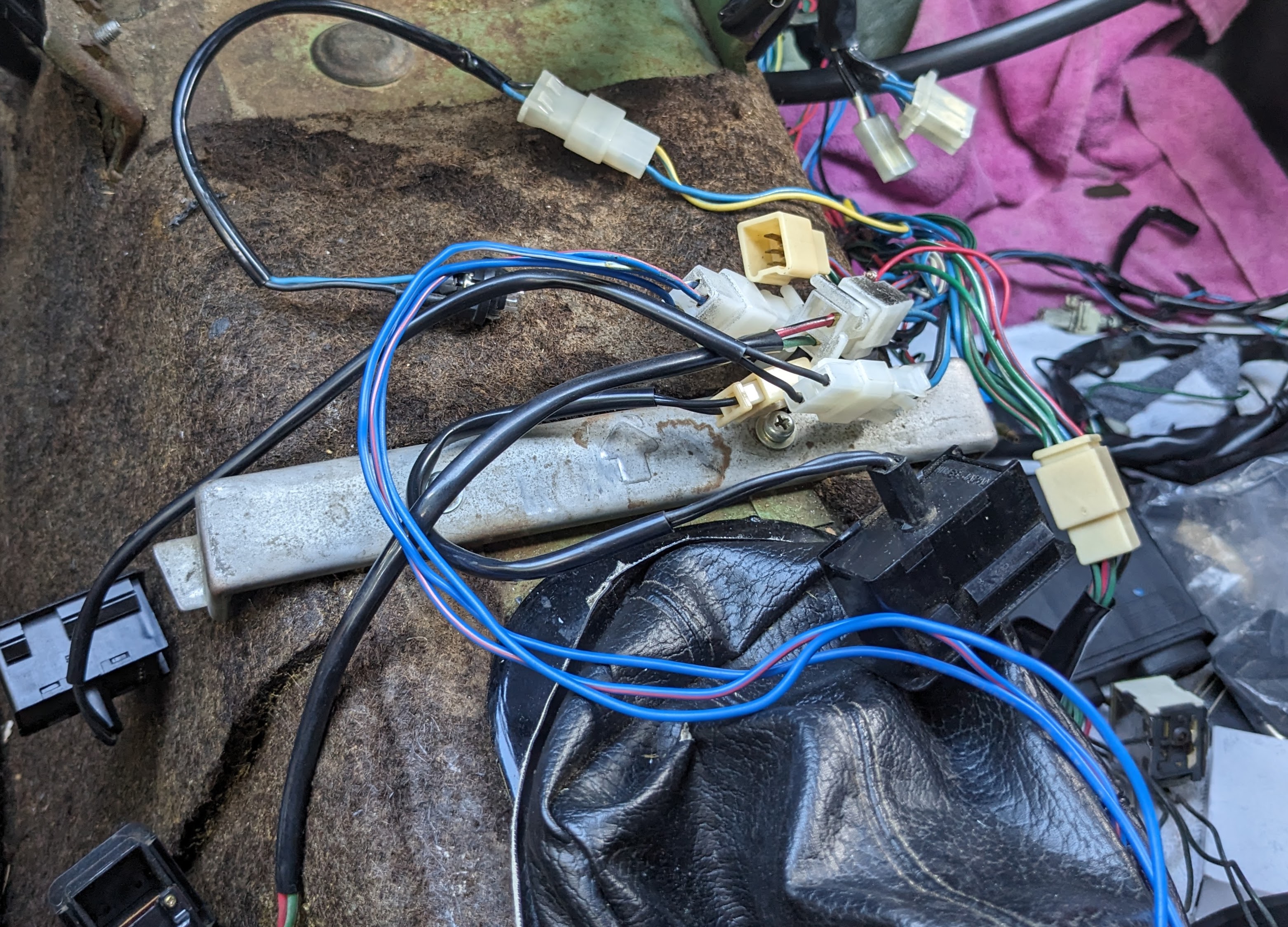
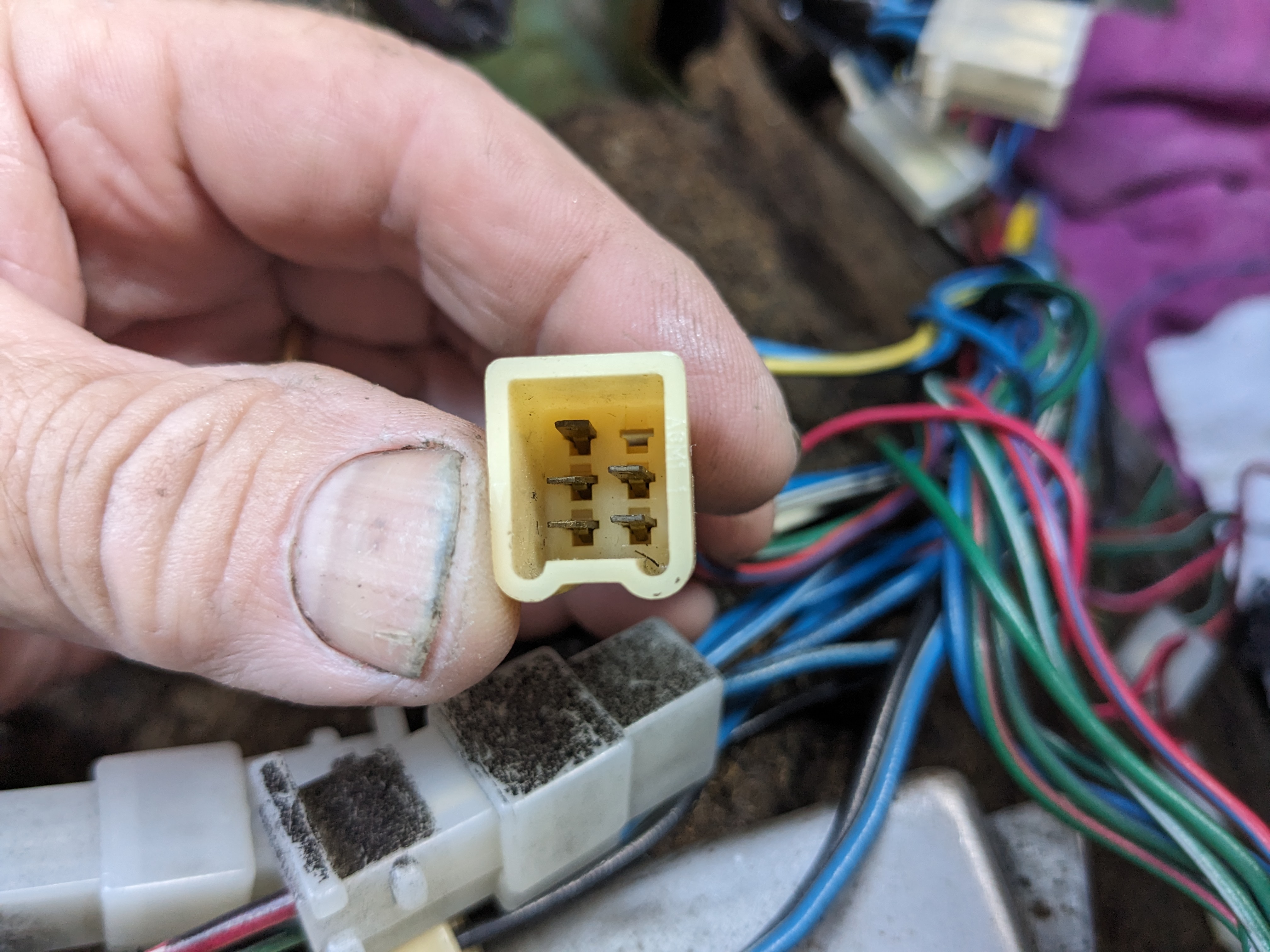
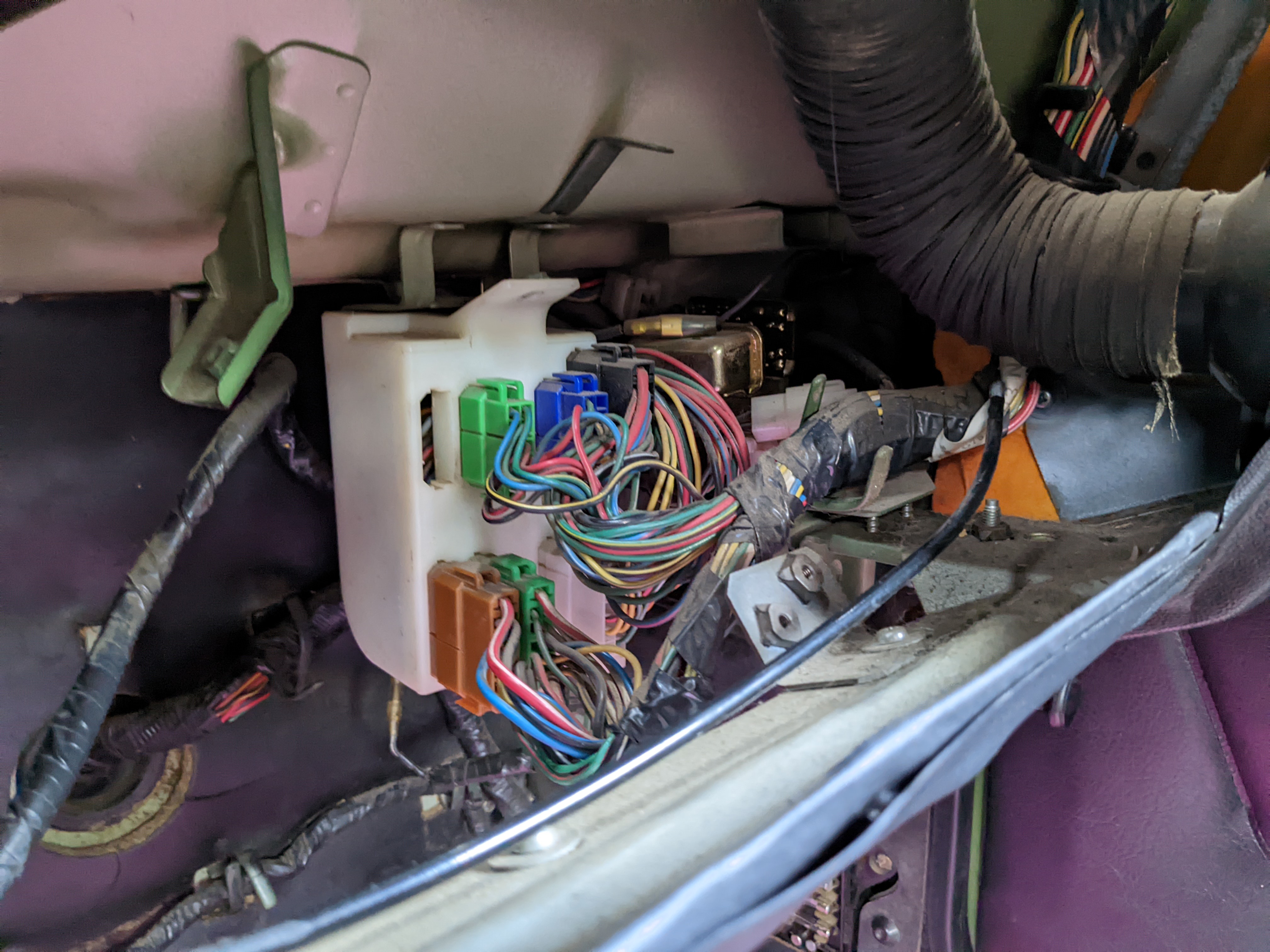
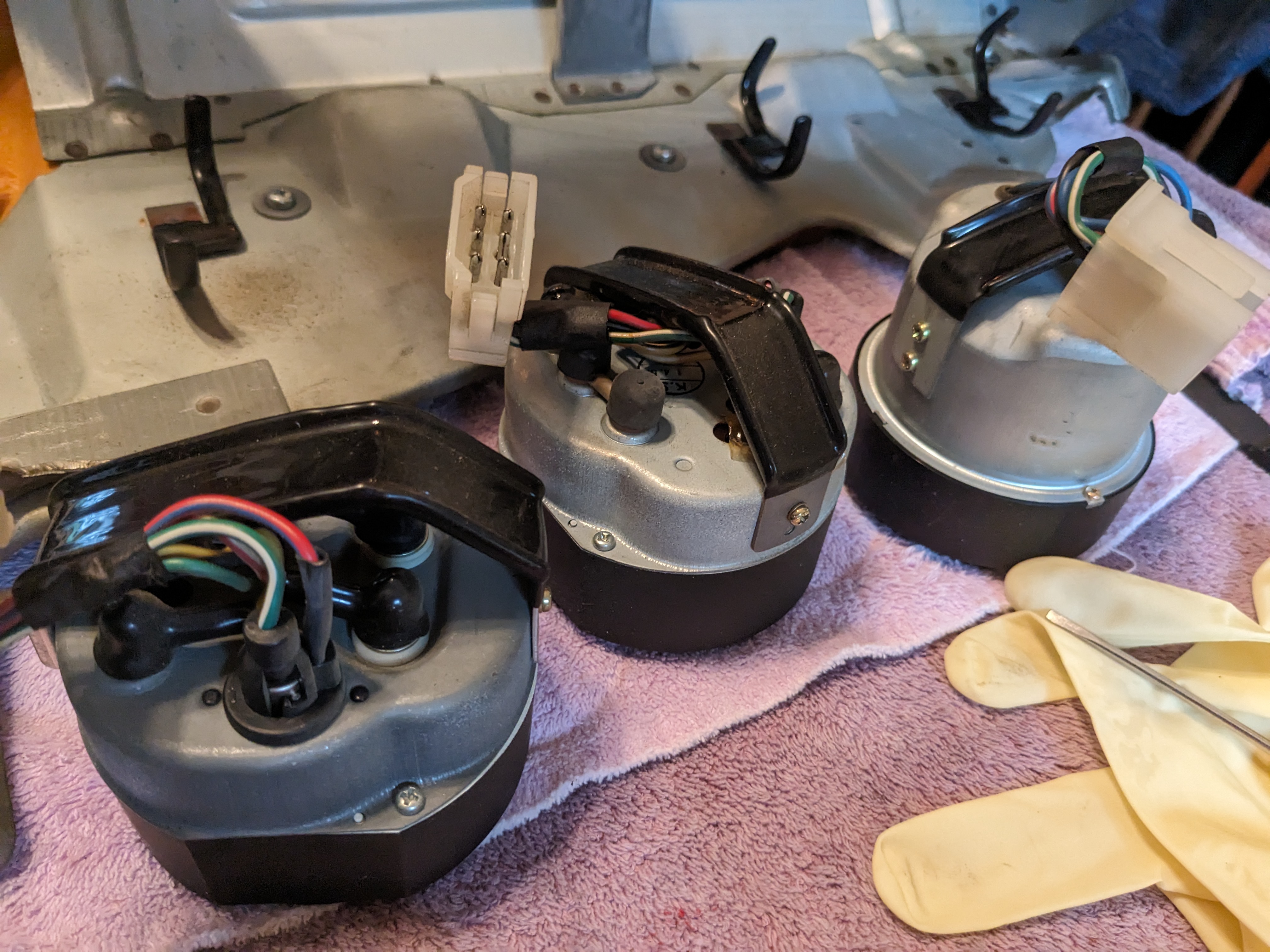
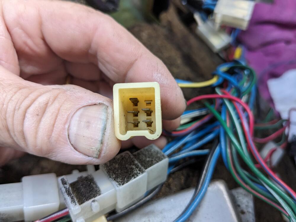
Going to assume the harness with cut blue is the radio harness. Everything else is accounted for, except for the 6 pin plug with small spades (edit - 3 wire blue variations is power antenna harness) I don't seem to have anything that connects here, one wire was cut & a fused line was added. Don't know what for. I'm going to assume again it was radio related, as no other accessories have been added to the car by the PO

-
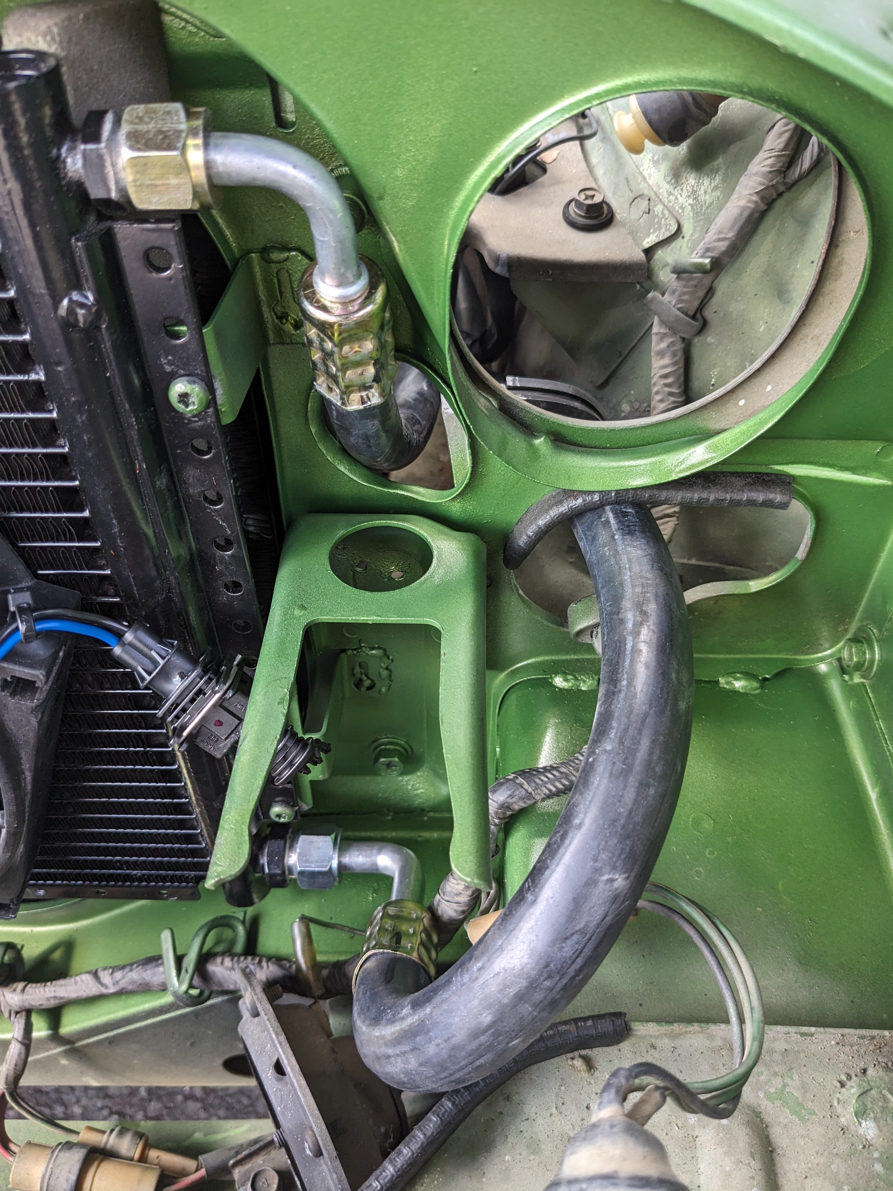
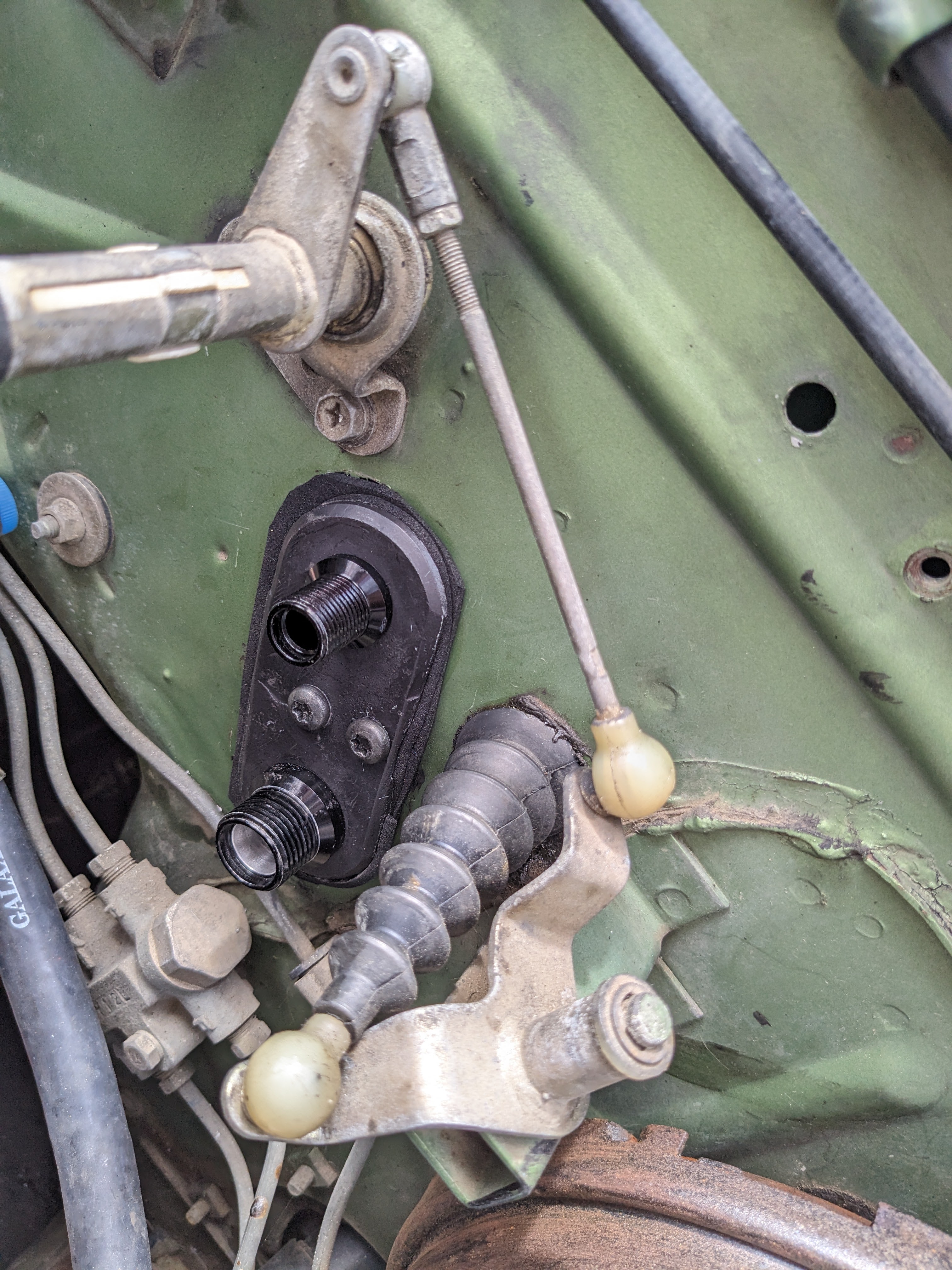
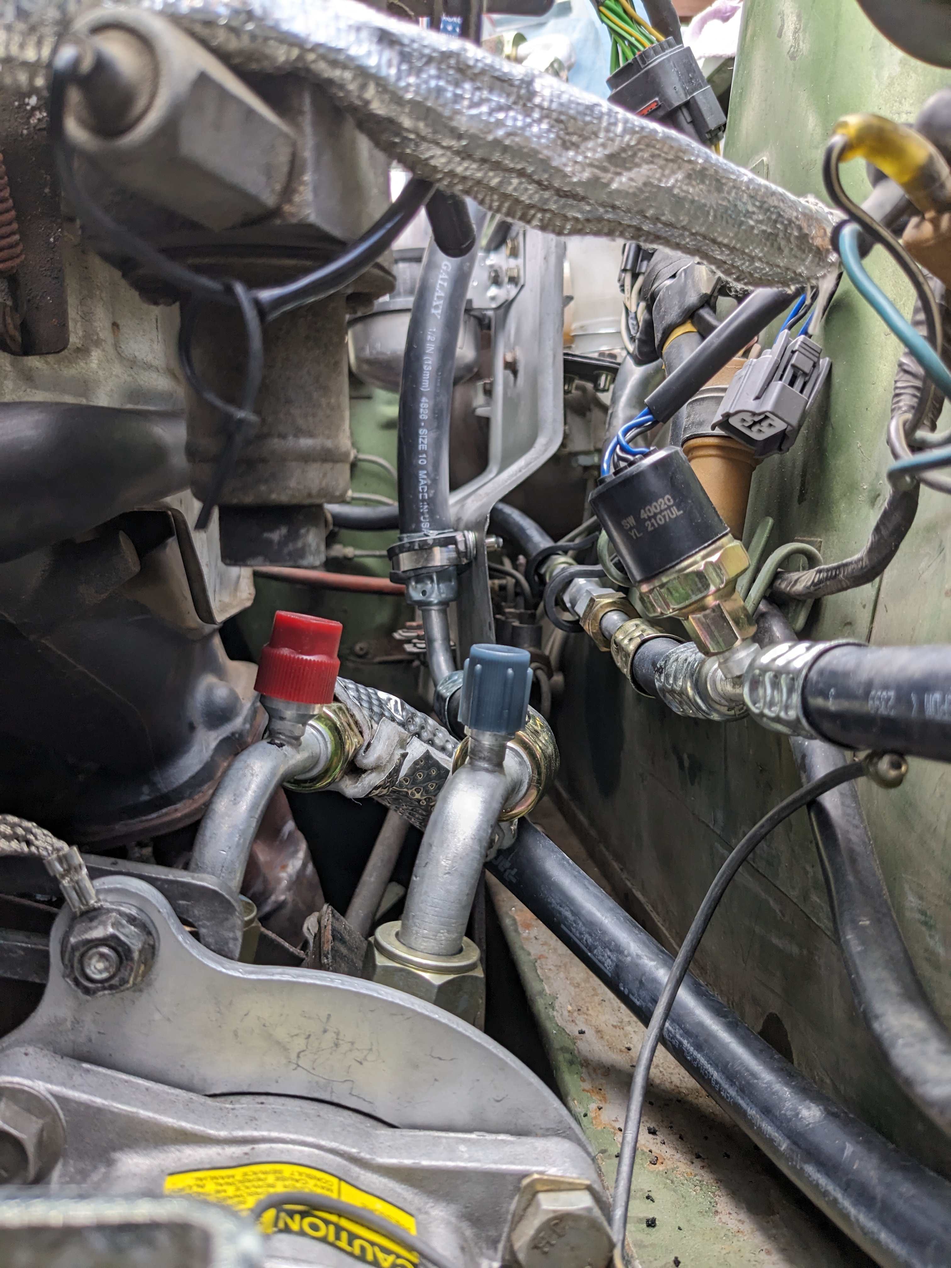
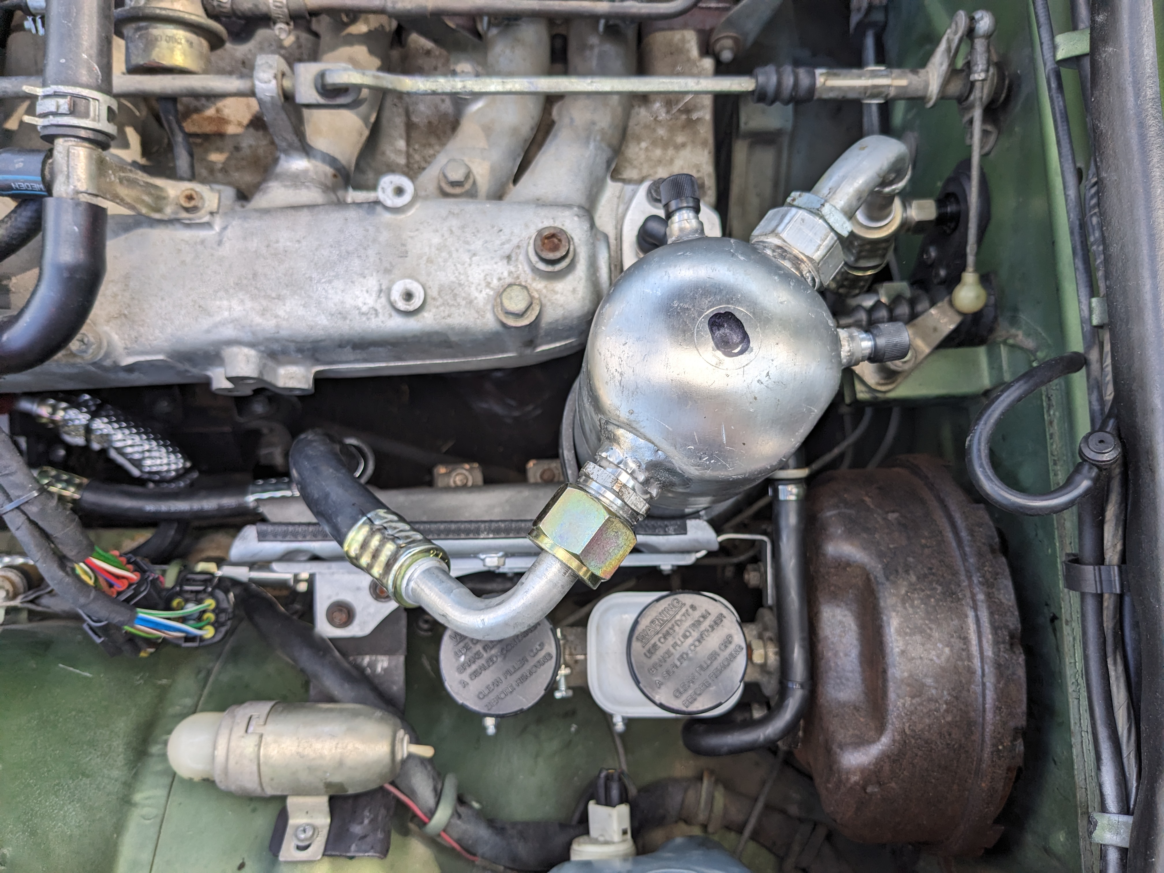
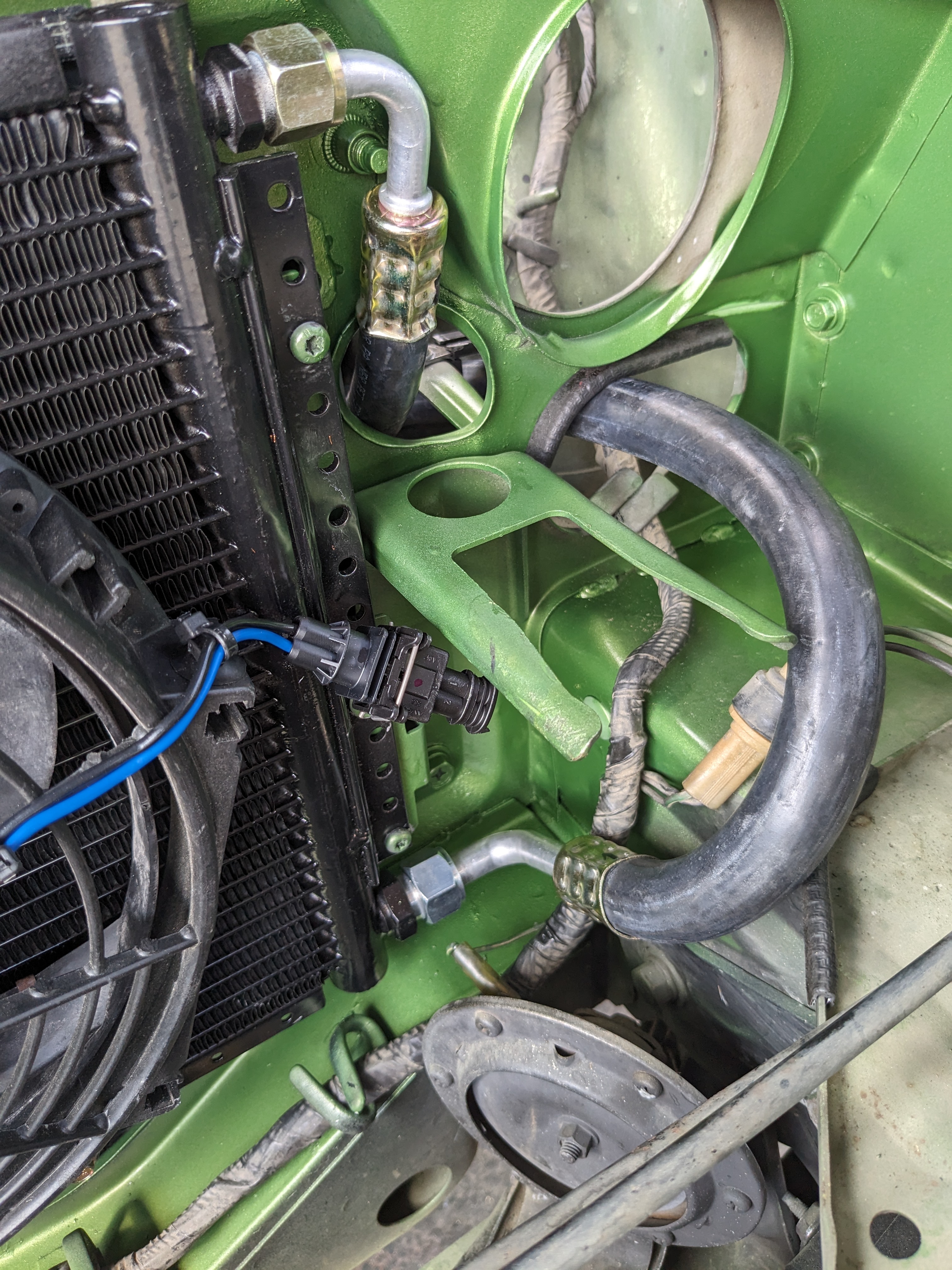
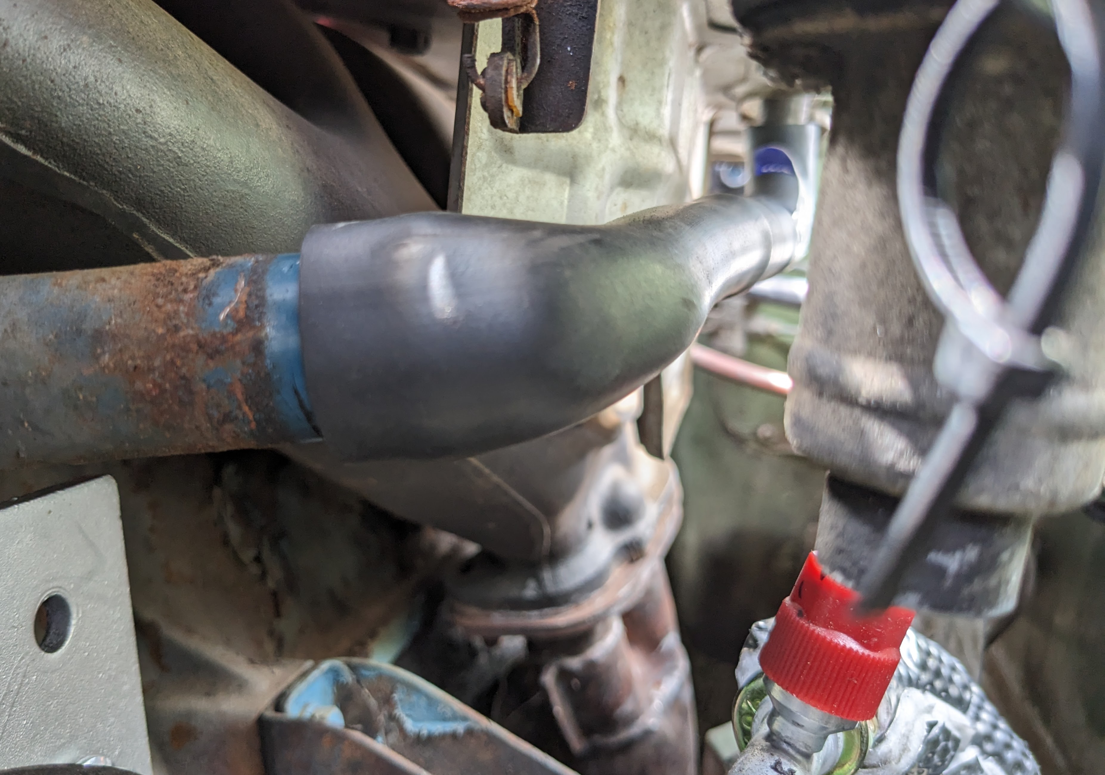
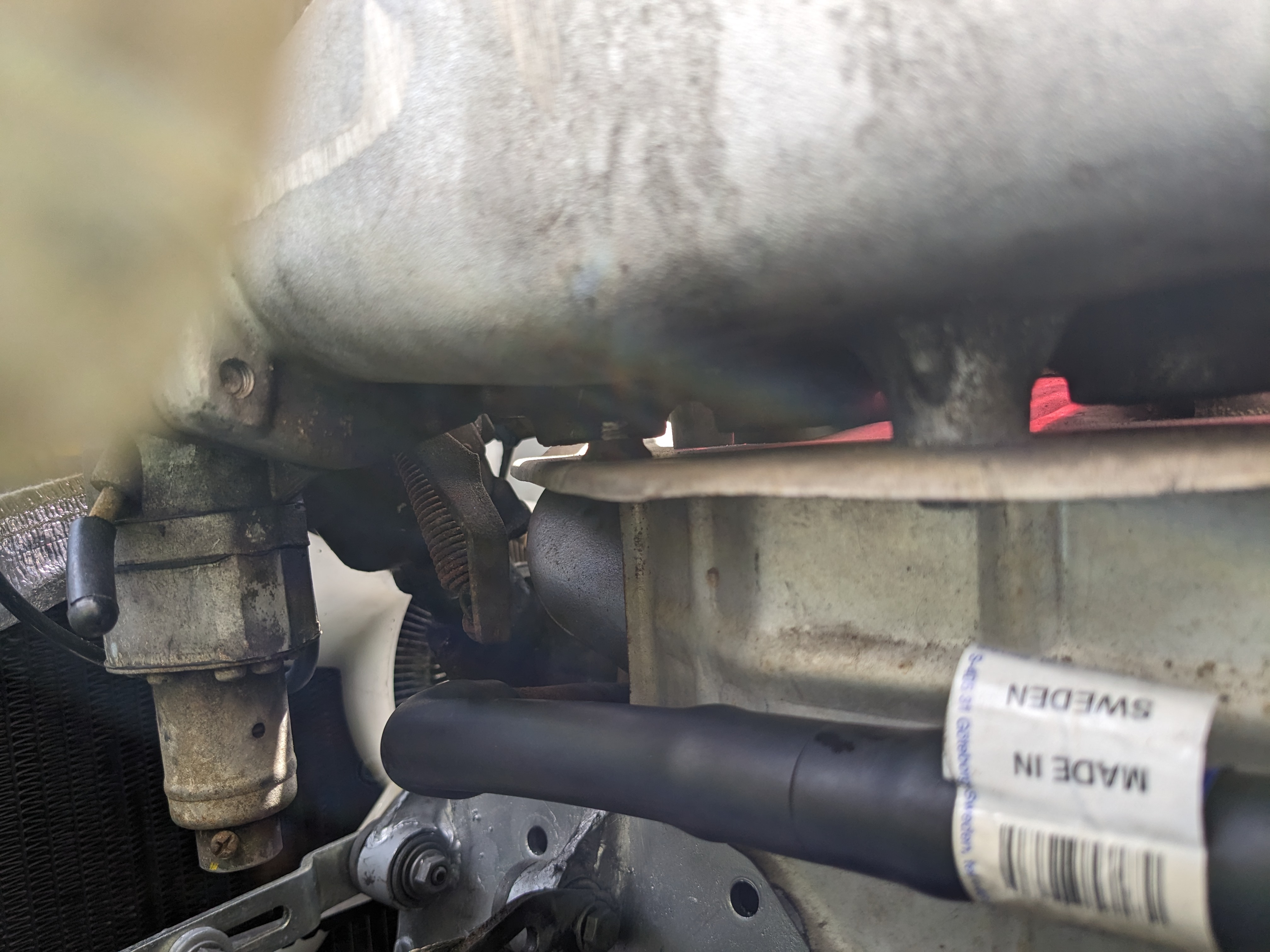
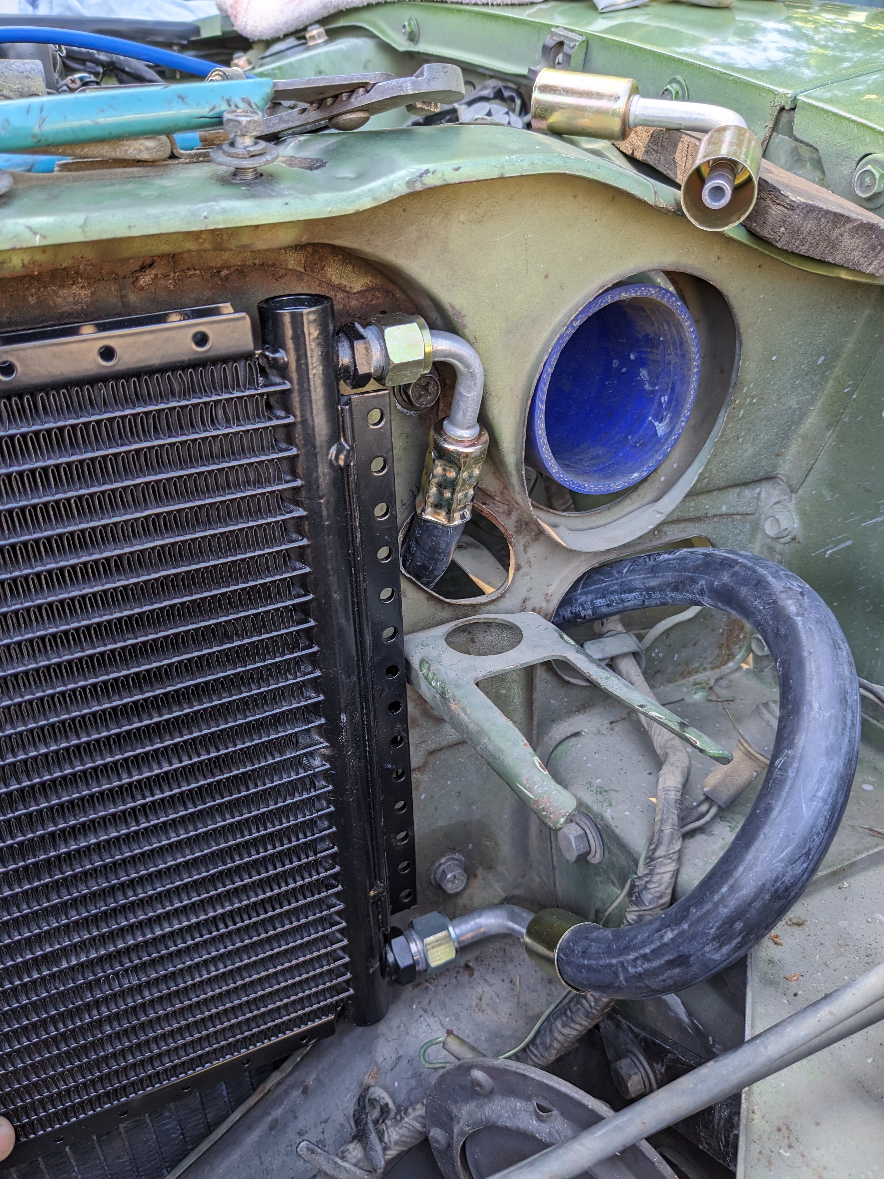
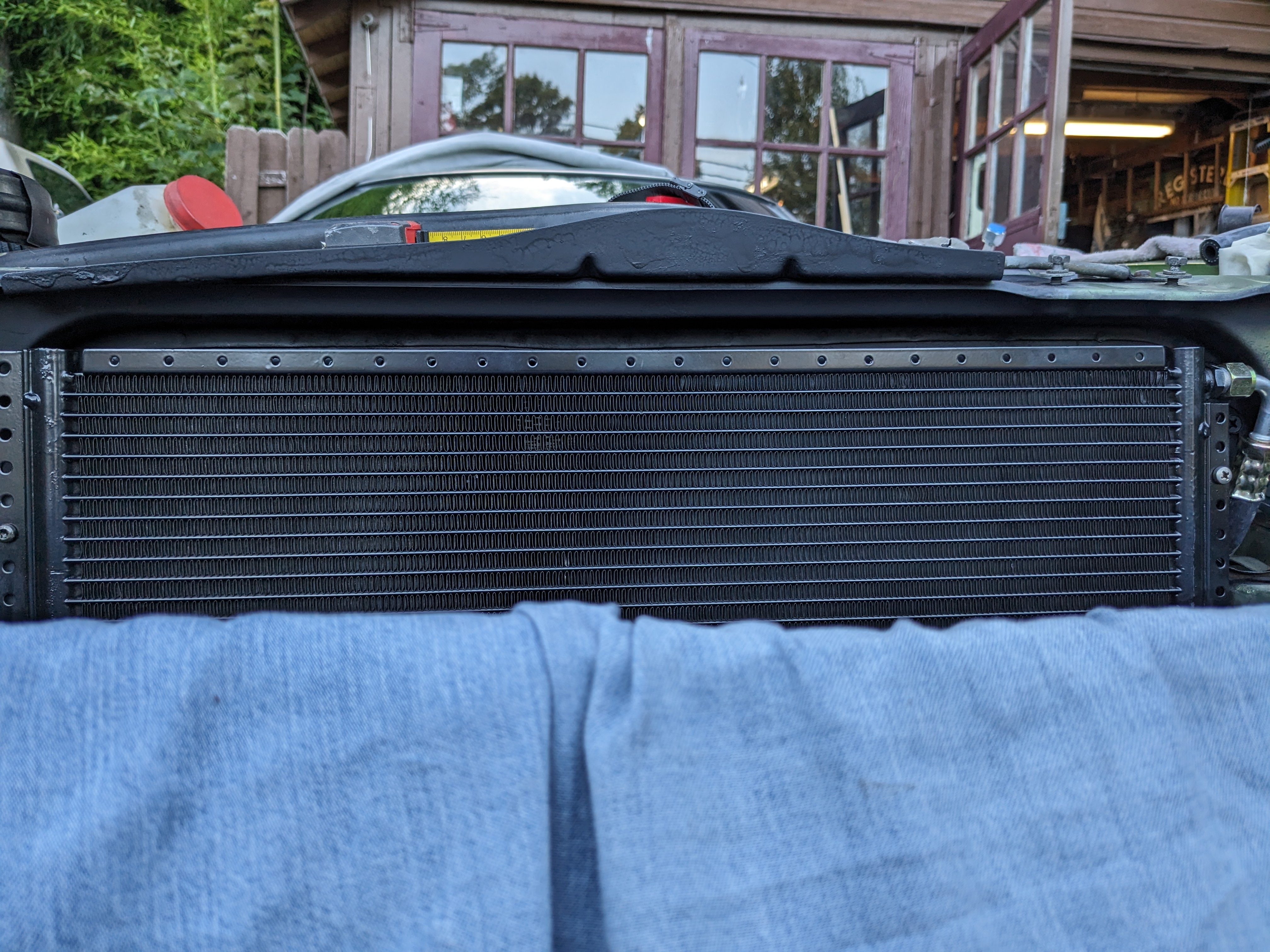
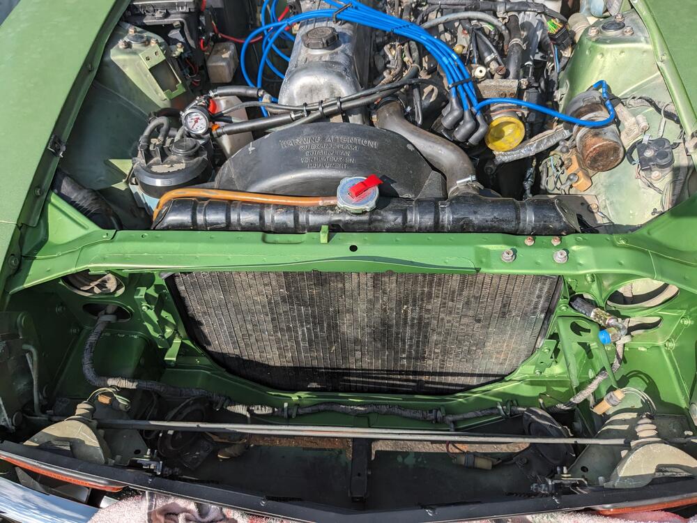
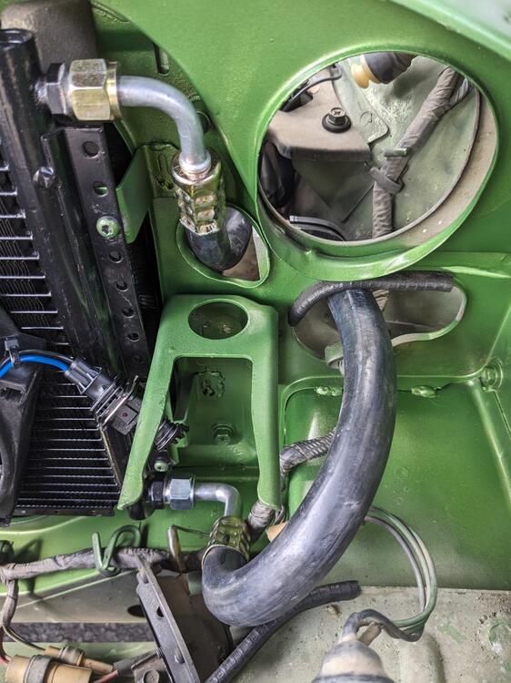
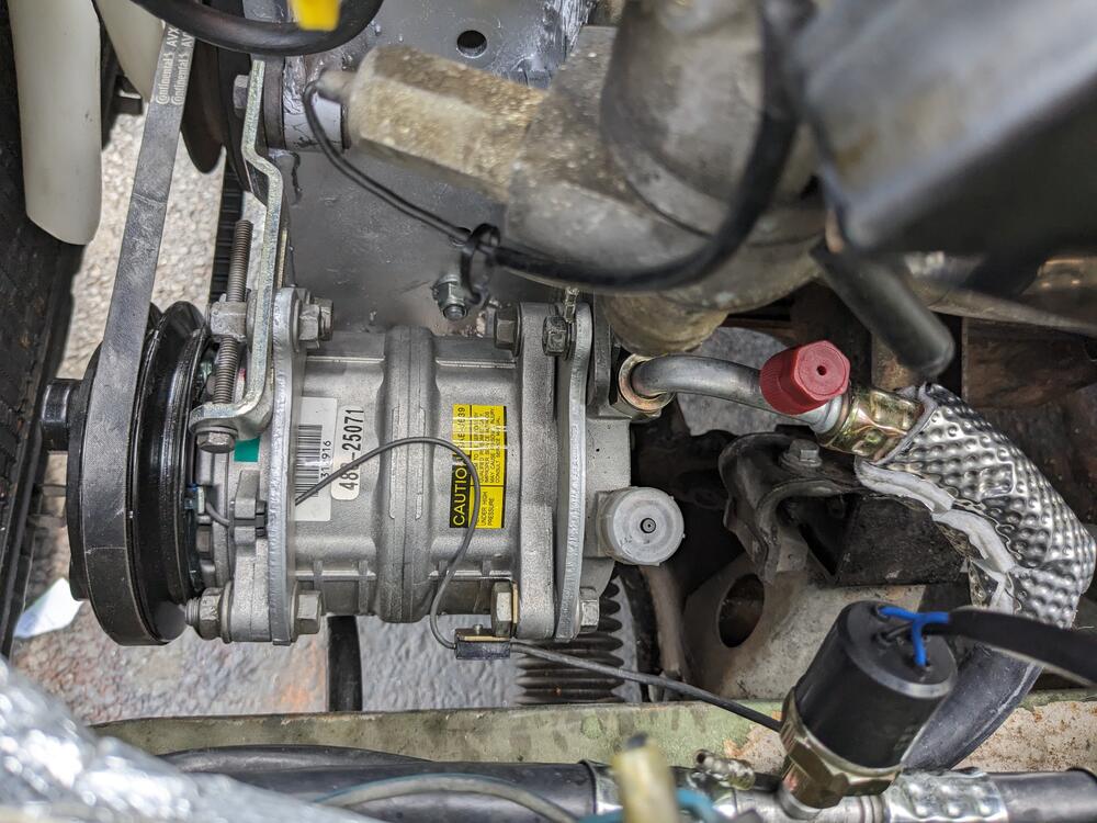
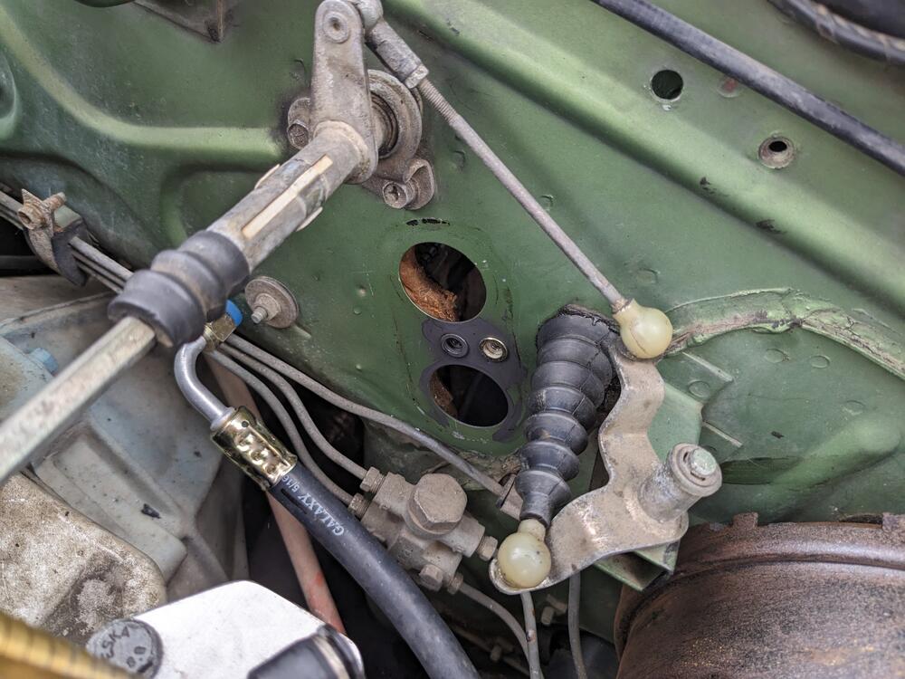
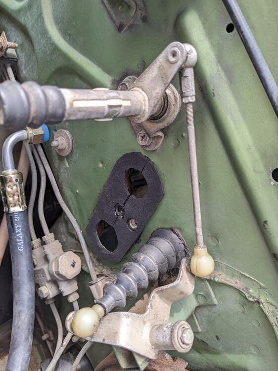
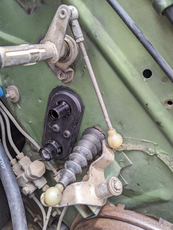
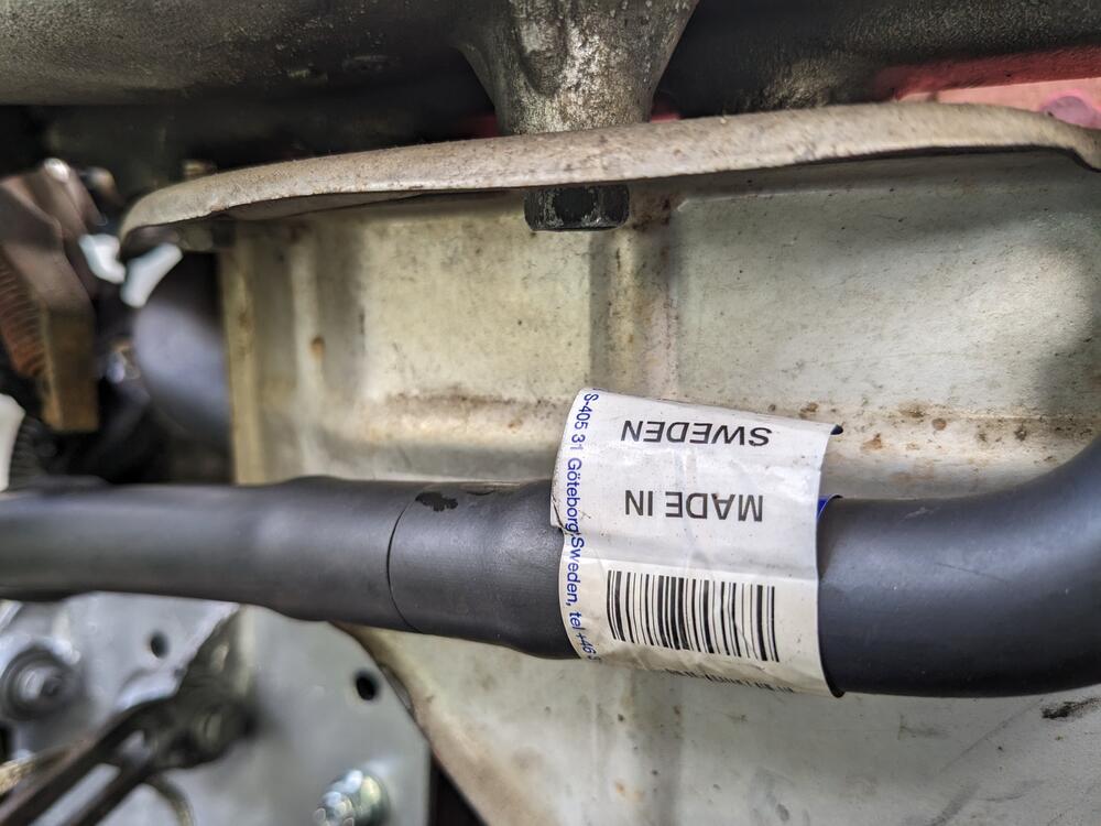
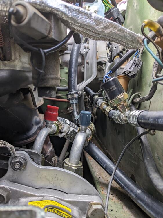
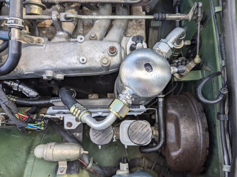
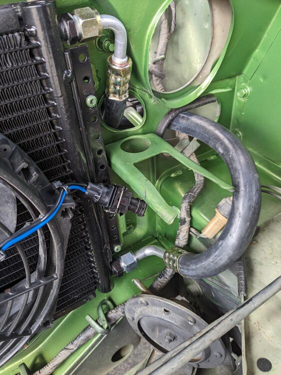
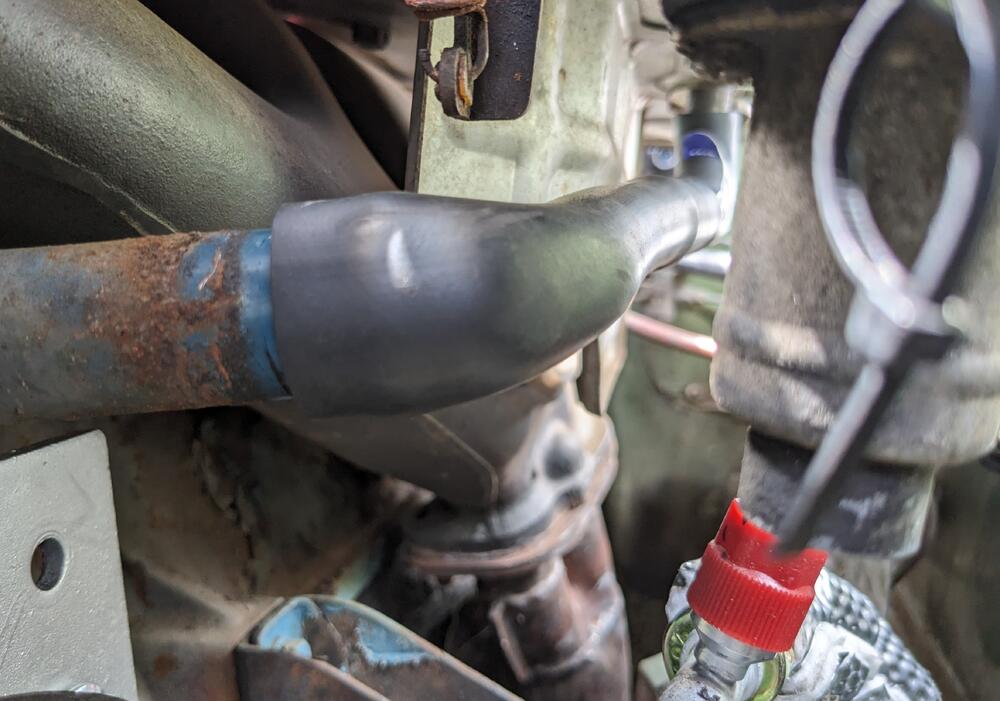
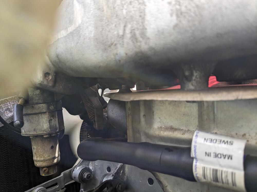
Still plugging away at the AC components. Condenser in, High side attached, made the #8 compressor line next I made sure the AC service equipment could attach to the line fitting, there is plenty of clearance off the heat shields Before I did the low side to the compressor, I took care of the old PCVC hose. Volvo PCV hose for a 740 has the correct end ID's - just not the correct offset of the 90º ends, so I cut it in half & re-oriented it. Clamped after confirming fit was good (not shown) then I made the low side hose from accumulator to compressor, has a 90º splice fitting to keep routing clean added another M5 rivnut to the heart shield to add a support clamp for the new line Had to add a second retain screw for the bulkhead fitting, so it would stay put when tightening the AC hose fittigns Just have to finish cleaning the heater box, then I can install the evaporator & draw down the system to vaccum test. Still have to wire the system & condenser fan circuit
-
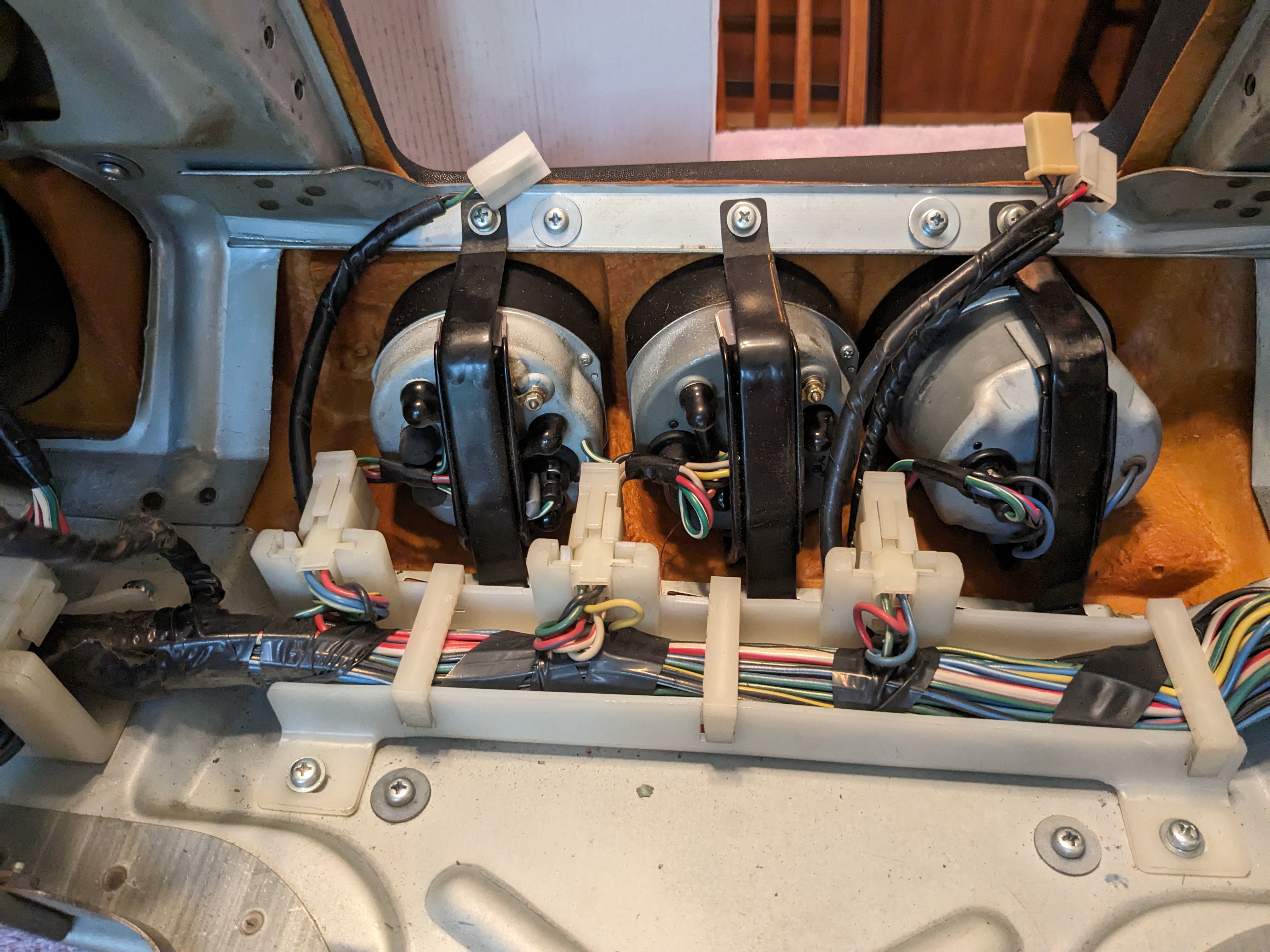
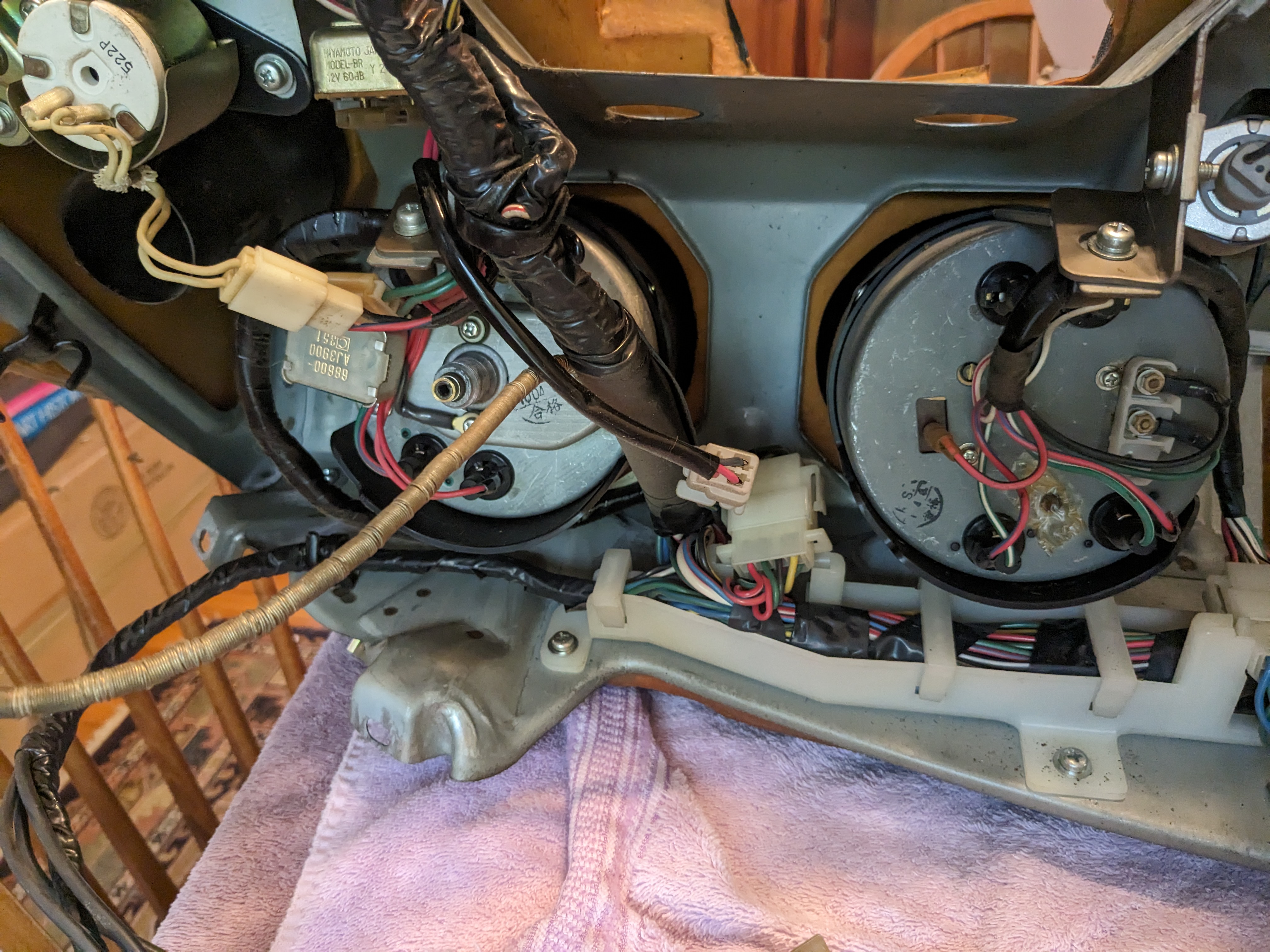
Reviewing your idea - I'm not sure adding a (relatively) bulky bridge harness behind the 3 pods make sense. The dash harness is so neat & tidy from the factory, I'm loath to mess with it's layout 🙂 Those wires feed in via one of the C connectors, so it would seem to make more sense to tap or bridge into the harness before it enters the dash. The gauges I'm adding are in the console, not in the dash. I'll look for where the switched blue wire is located in the C connectors, the Voltmeter does not use a constant feed like the Ammeter. Nah, I want to fix the stock clock if possible, I prefer the old analog display clocks.
-
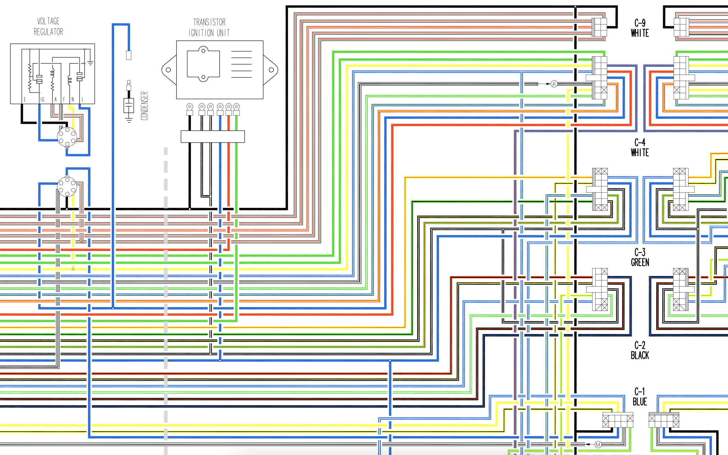
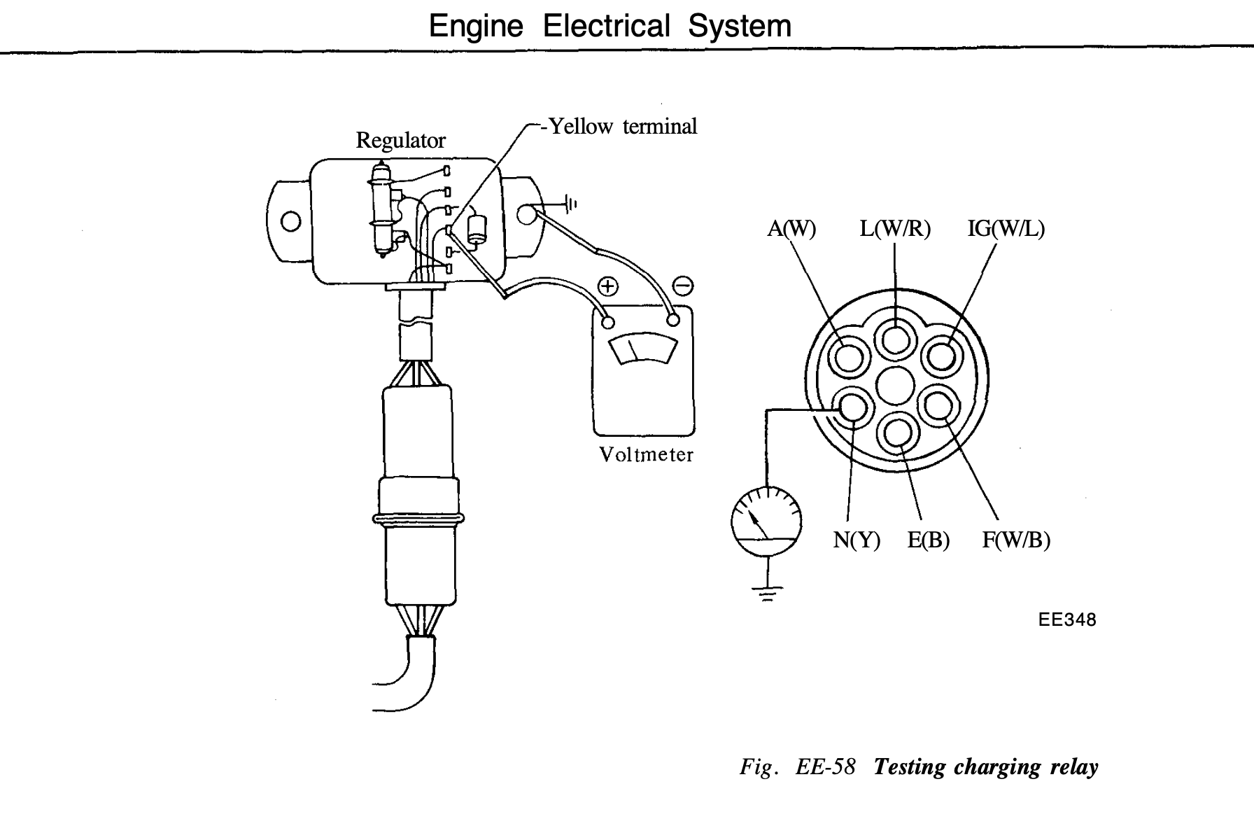
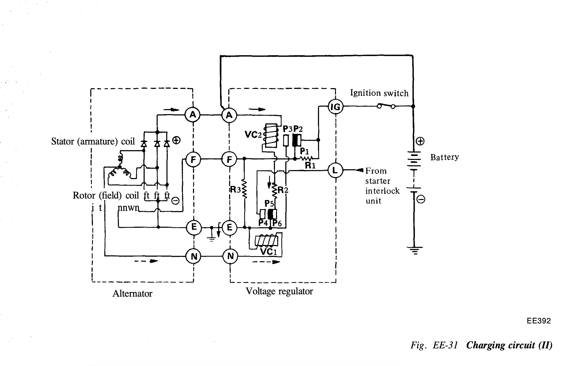
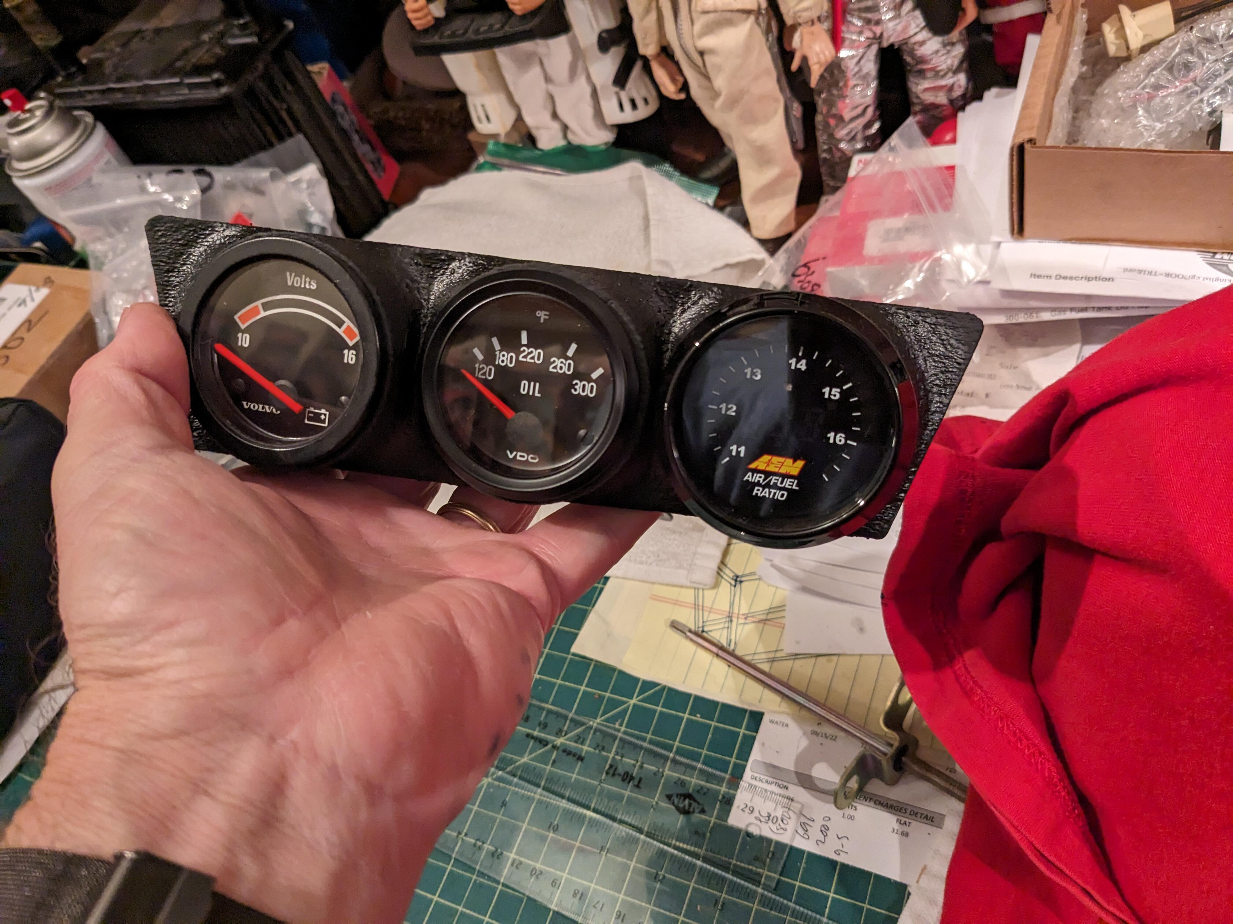
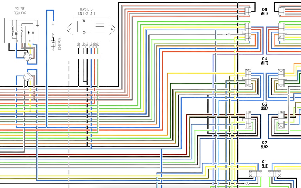
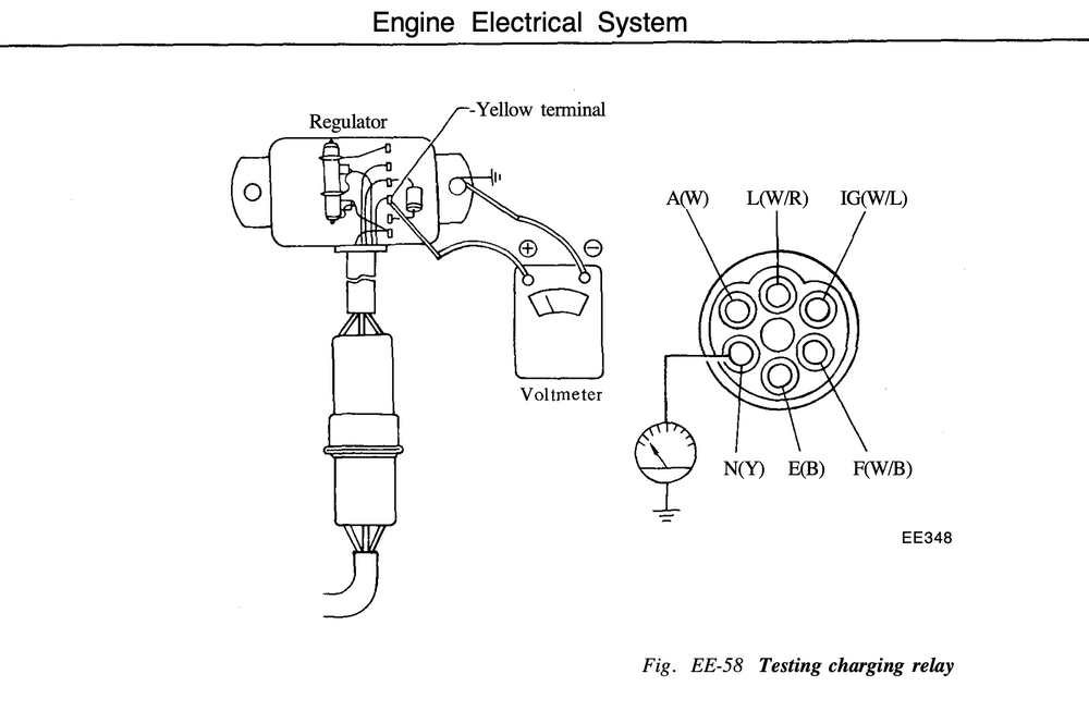
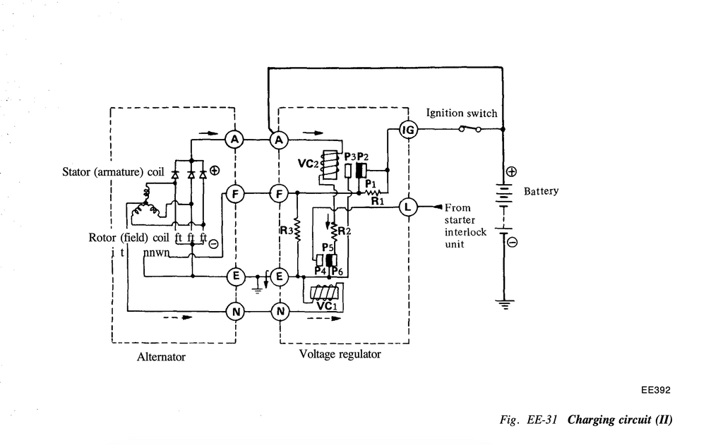
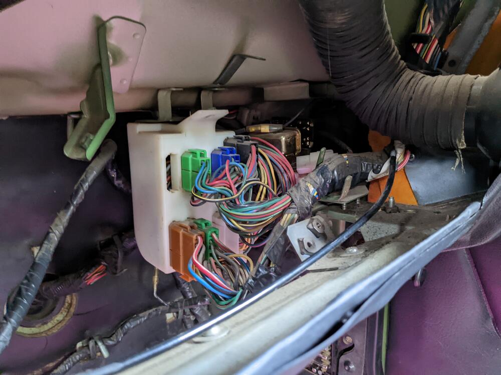
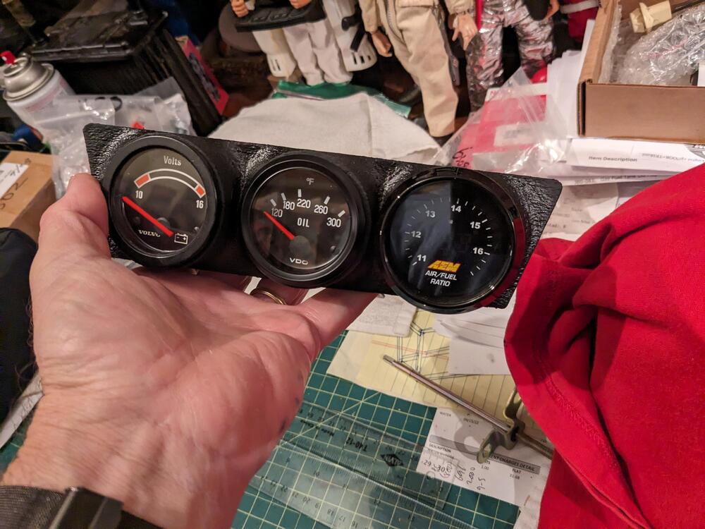
Going to piggy-back off this old thread rather than make a new one - the goal for me is to add a Voltmeter, (three gauge pod, replacing radio - I need to add a WBO2 in prep for the V6 conversion) not replace the stock ammeter though. Trying to figure out which wire in the dash harness would make sense to tap into, to get an accurate charging voltage value. Something from the Voltage regulator would seem to make sense, however I have a hard time cross-referencing these old line diagrams against the schematics. Any pointers? I'm assuming the C-x connectors are the ones at the fuse/relay panel
-
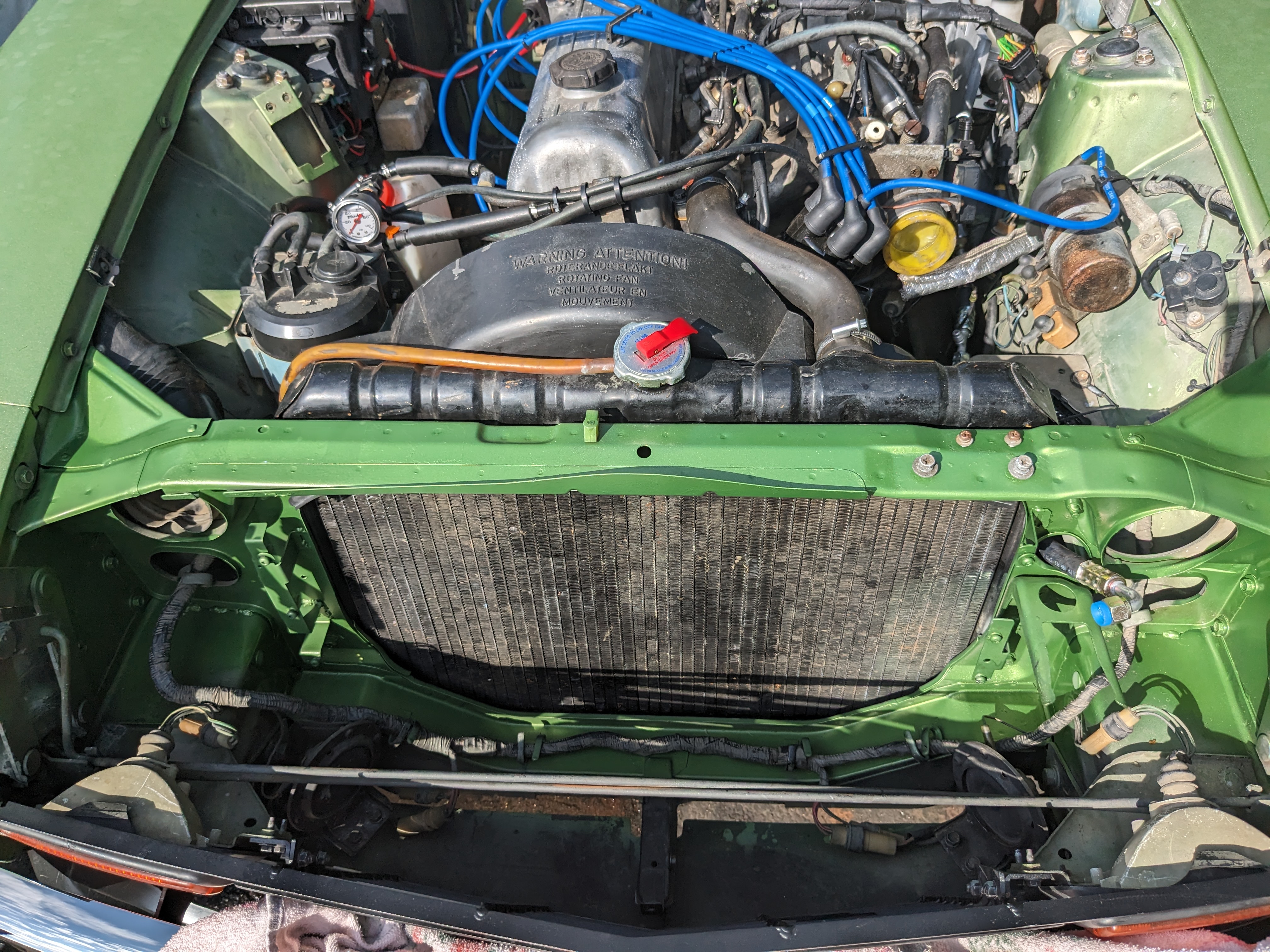
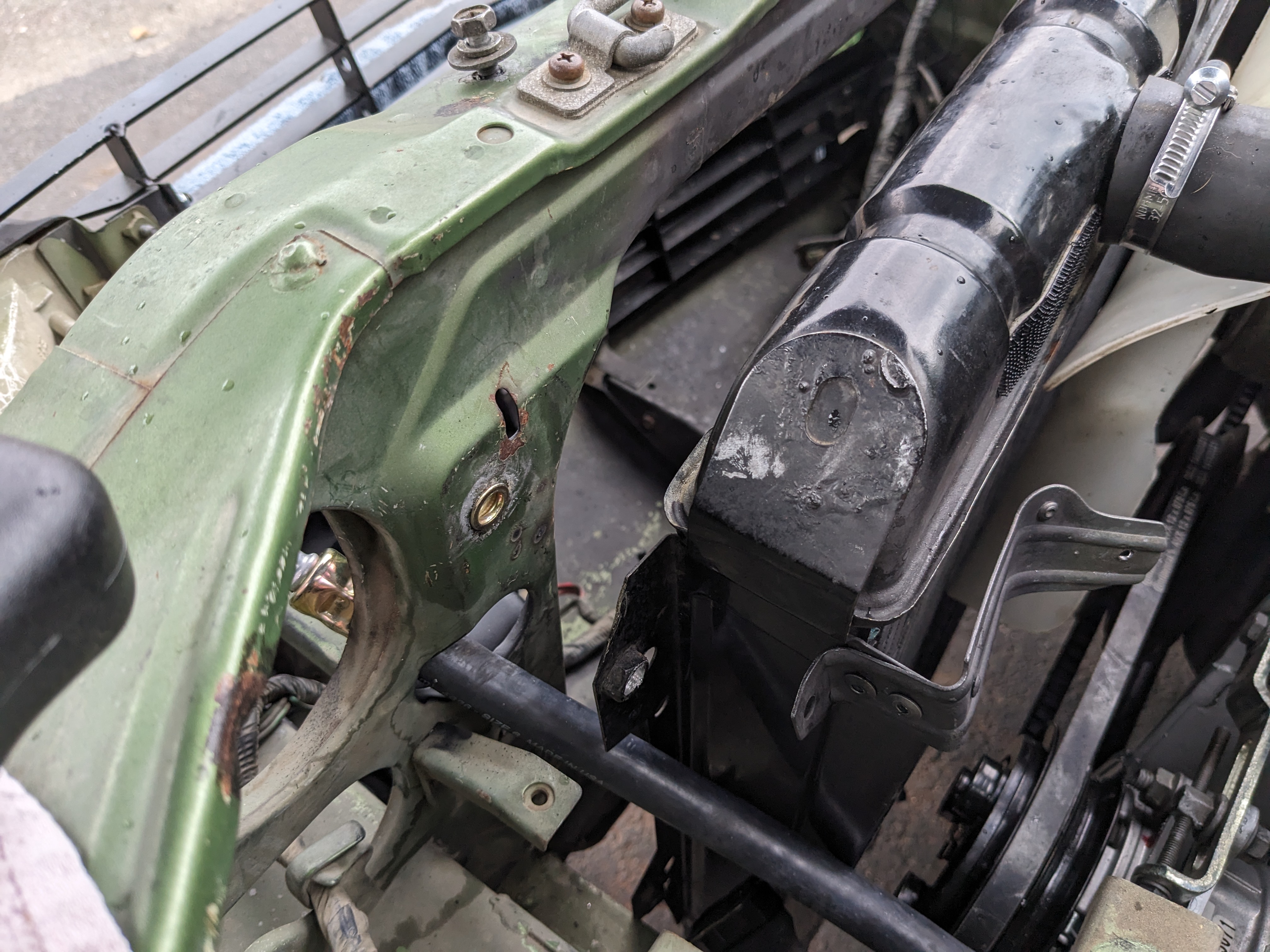
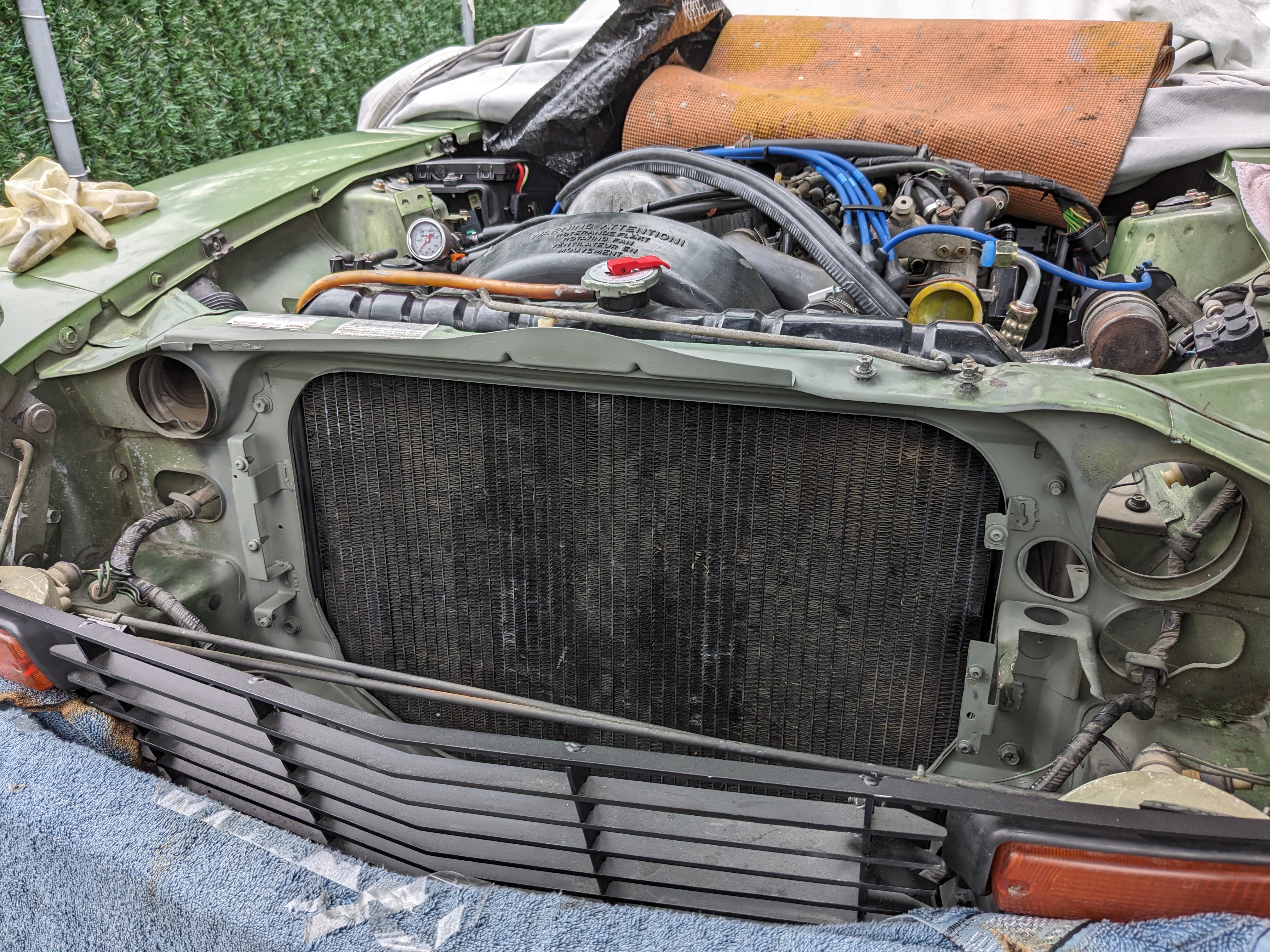
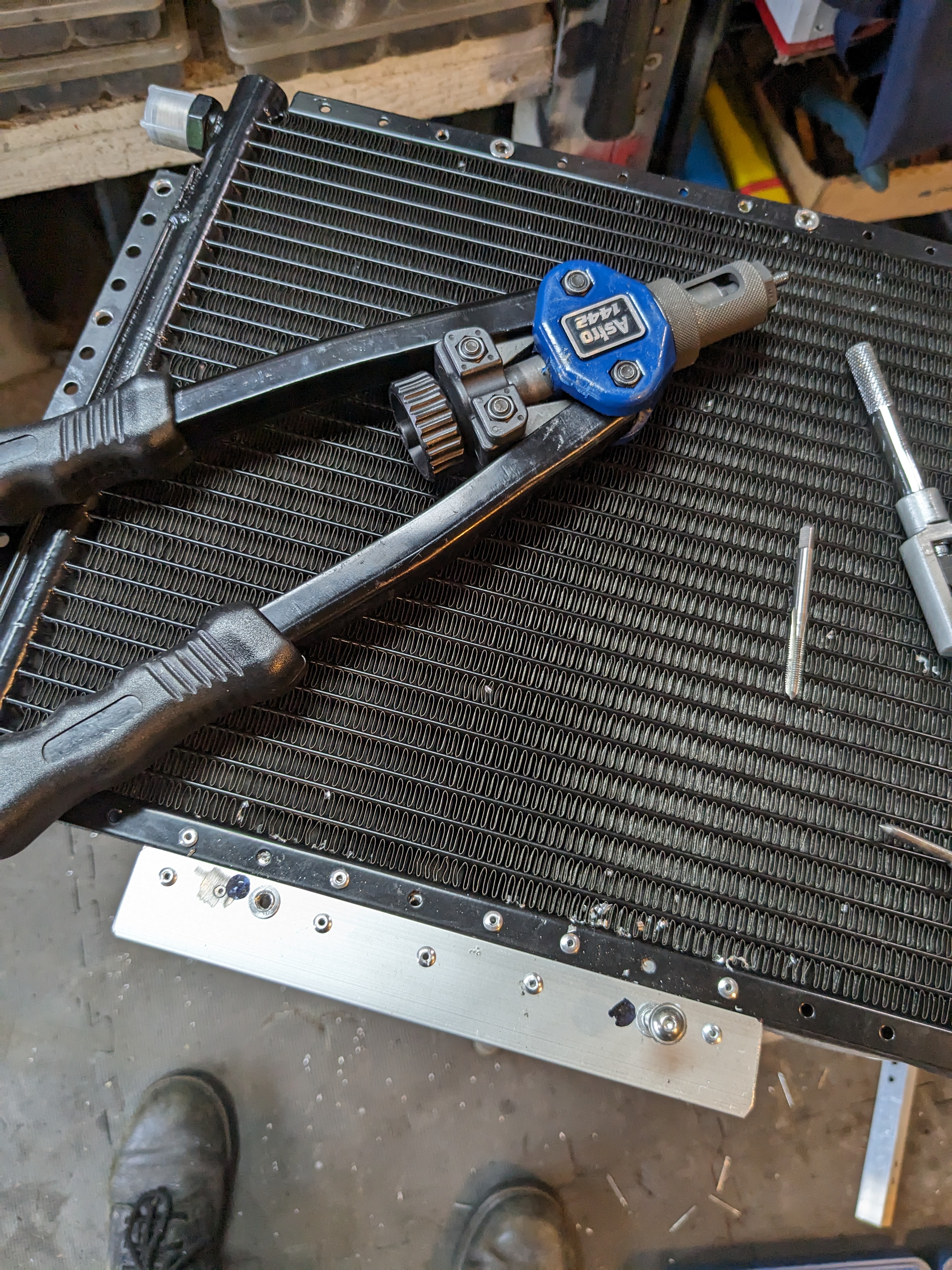
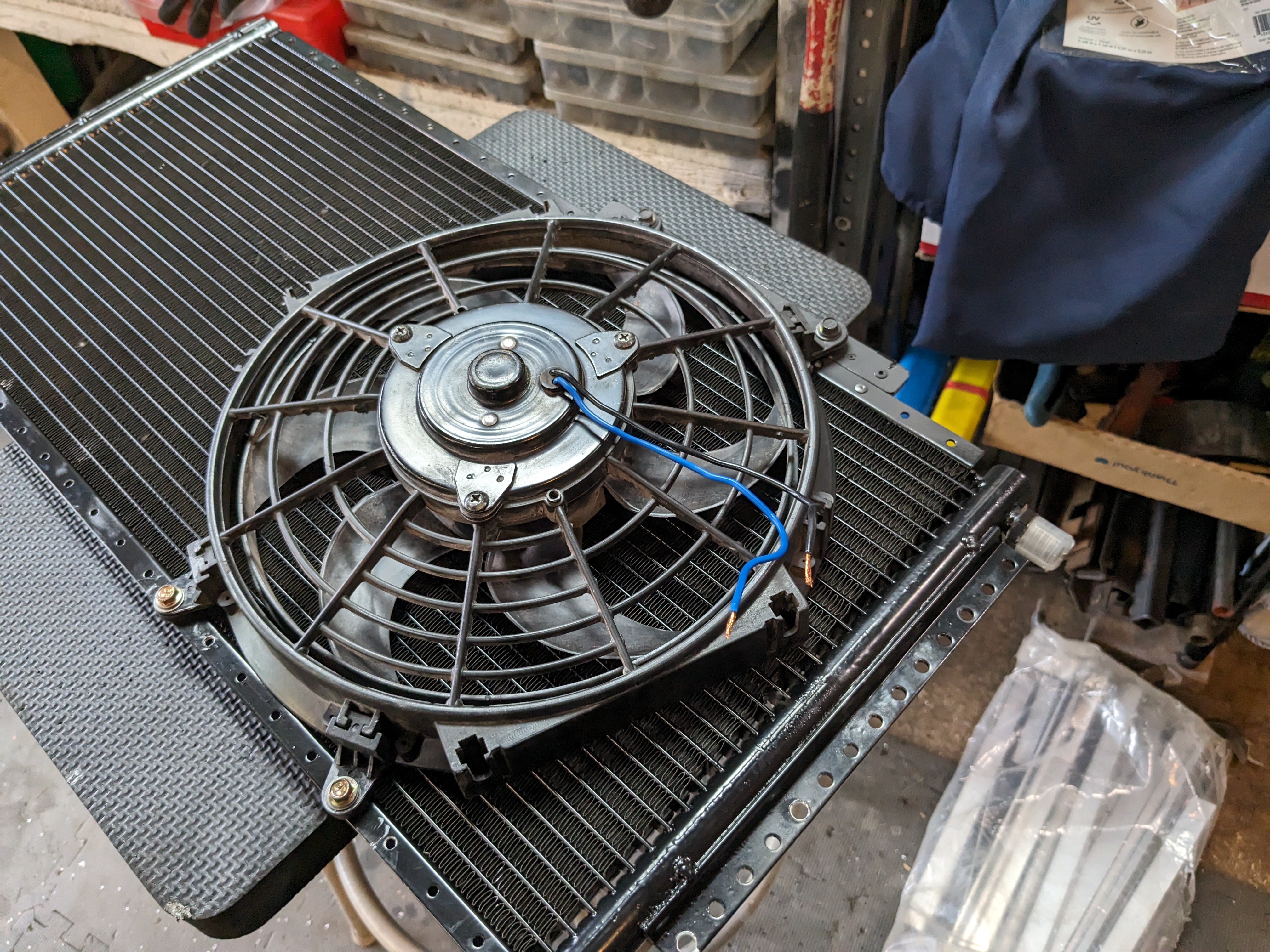
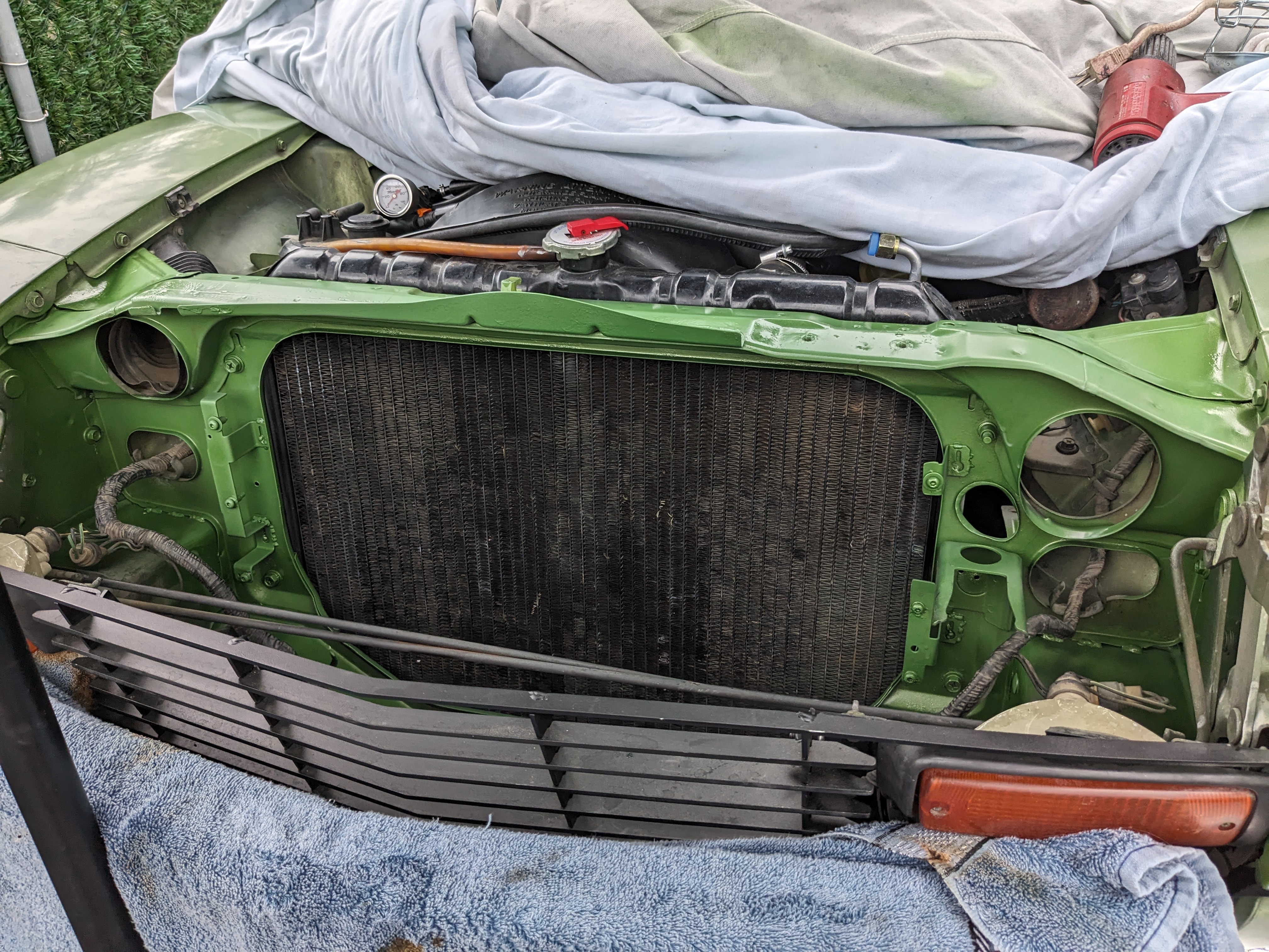
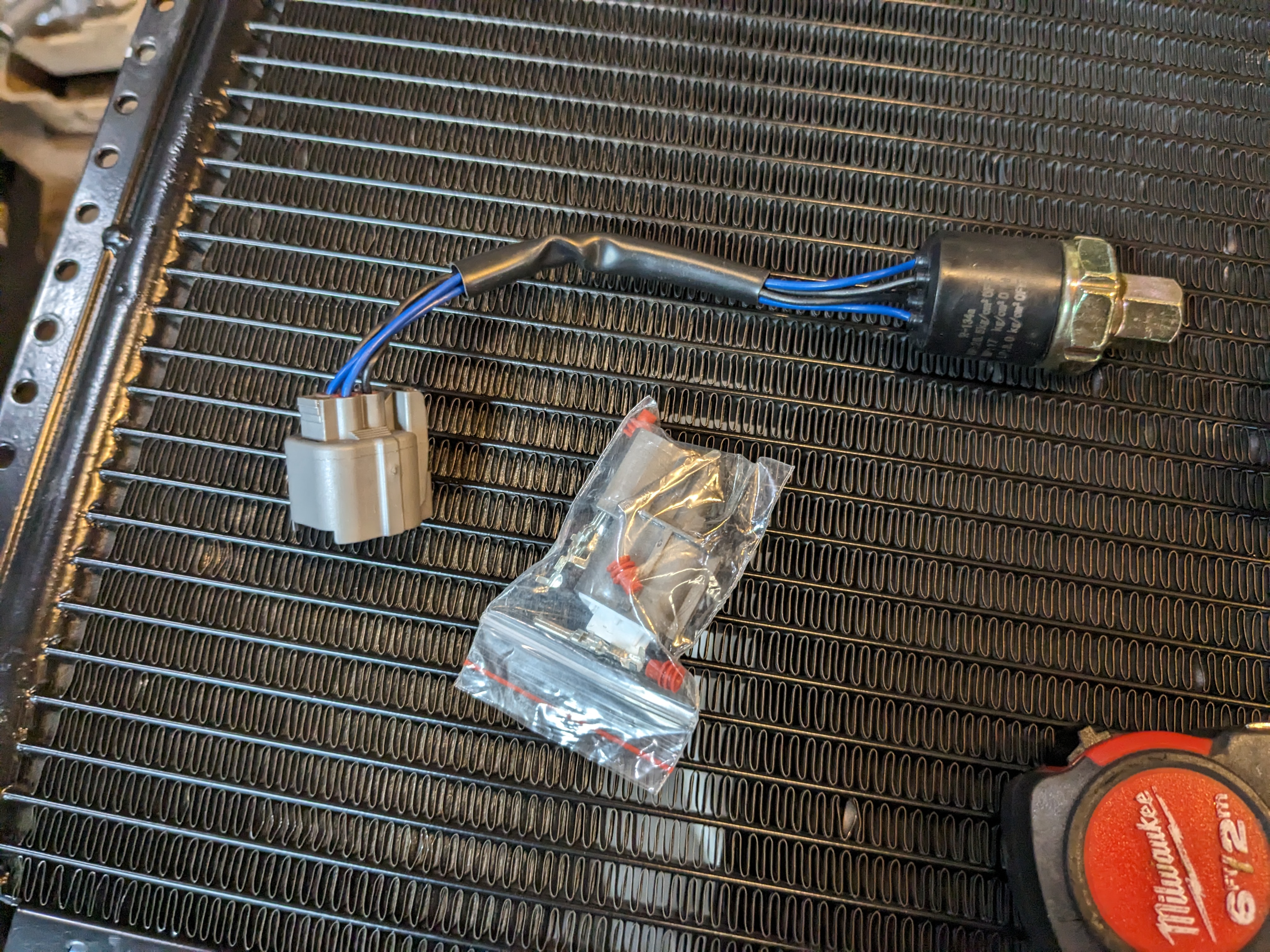
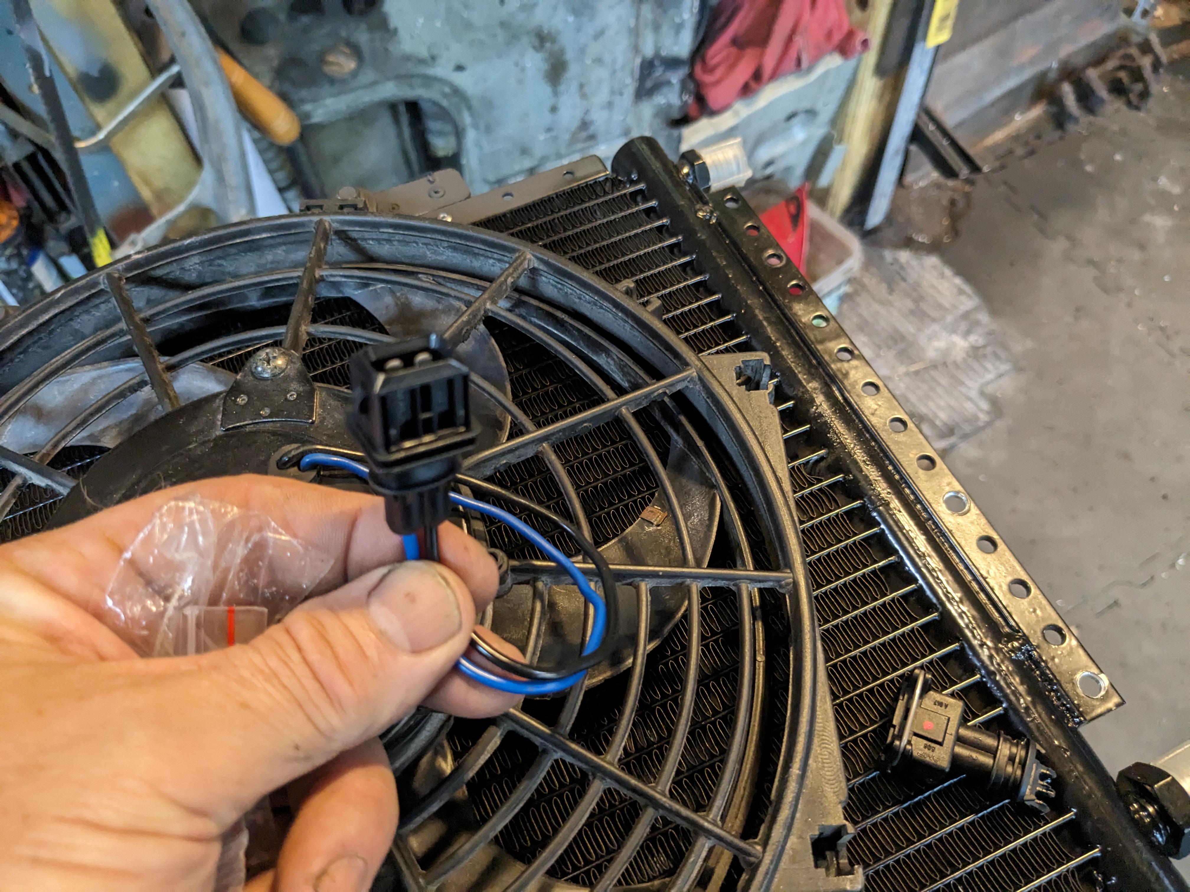
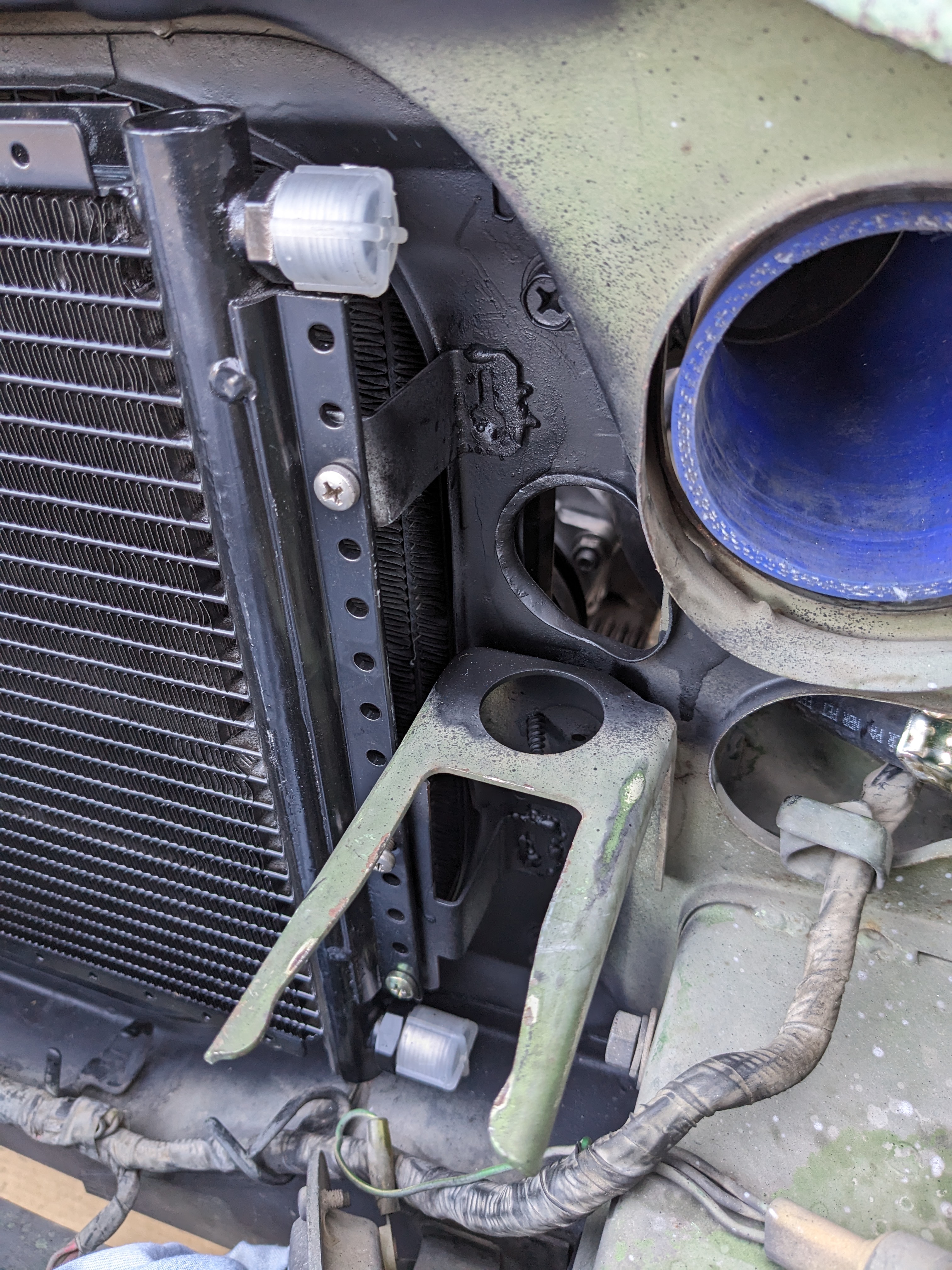
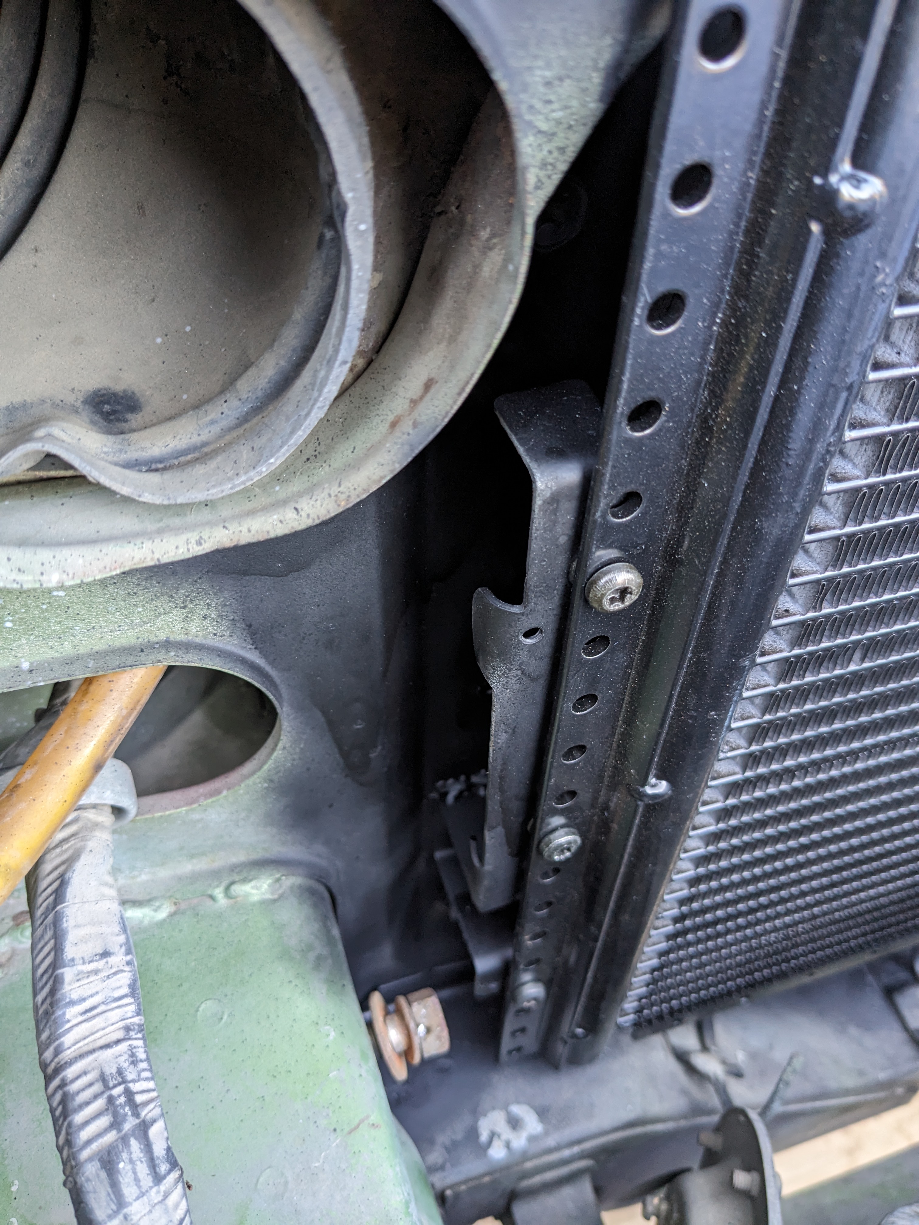
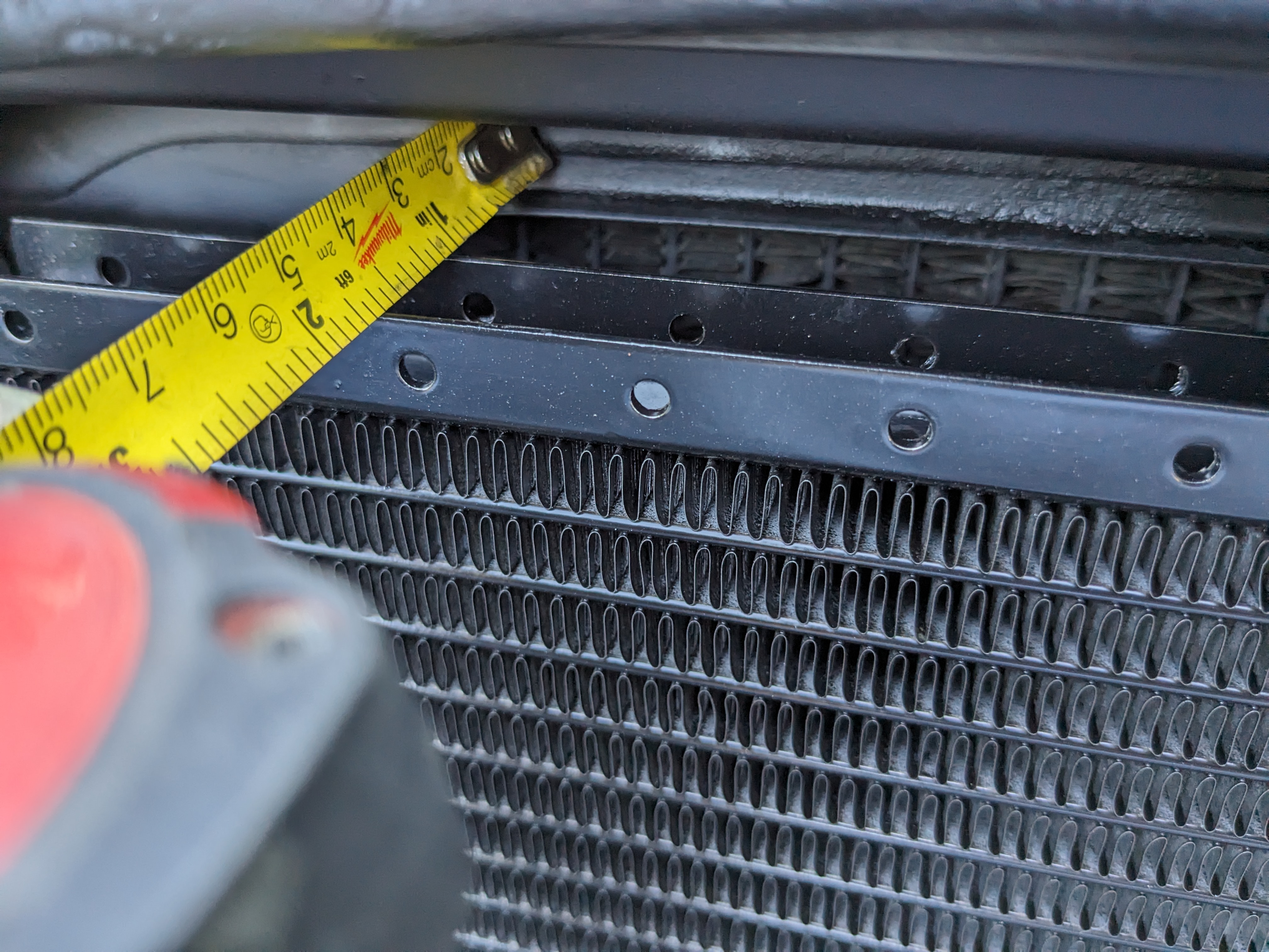
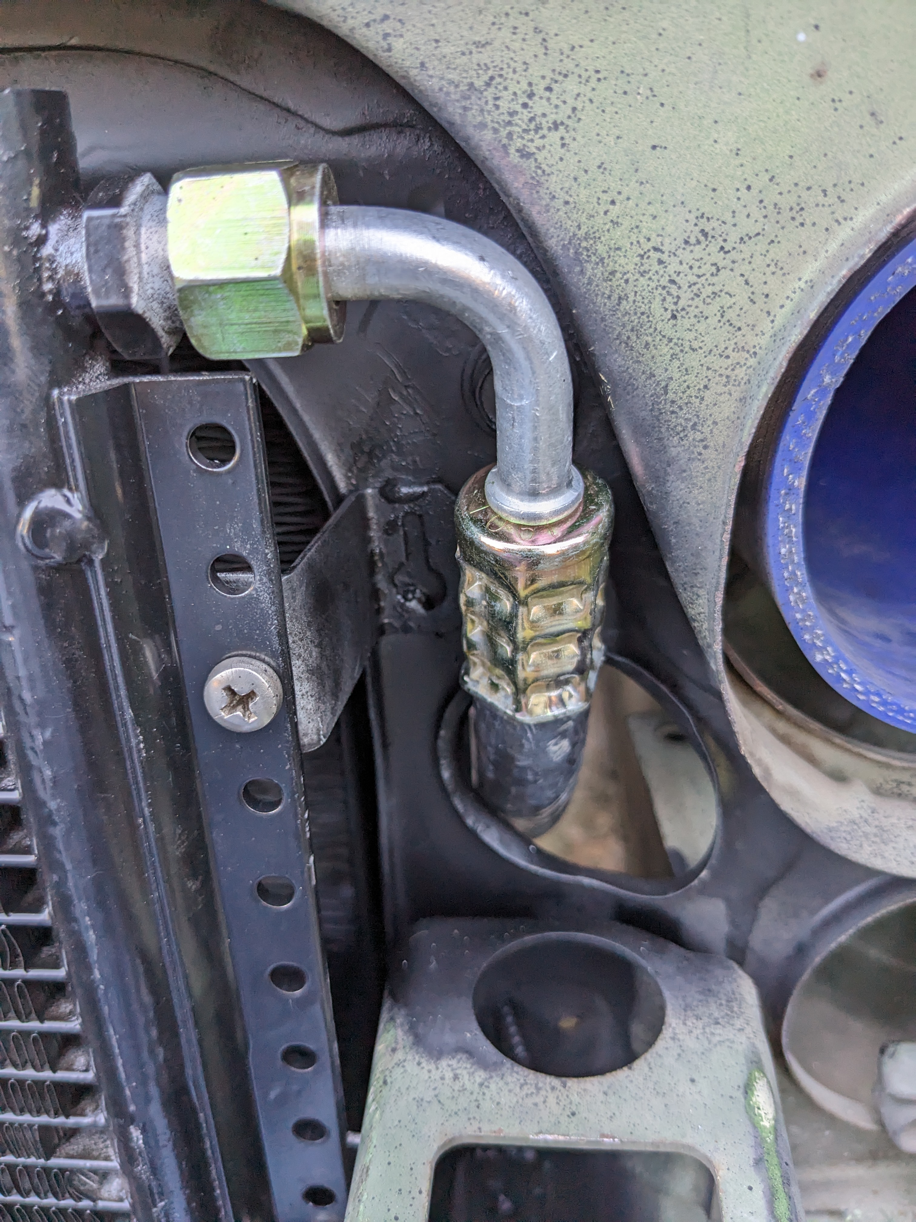
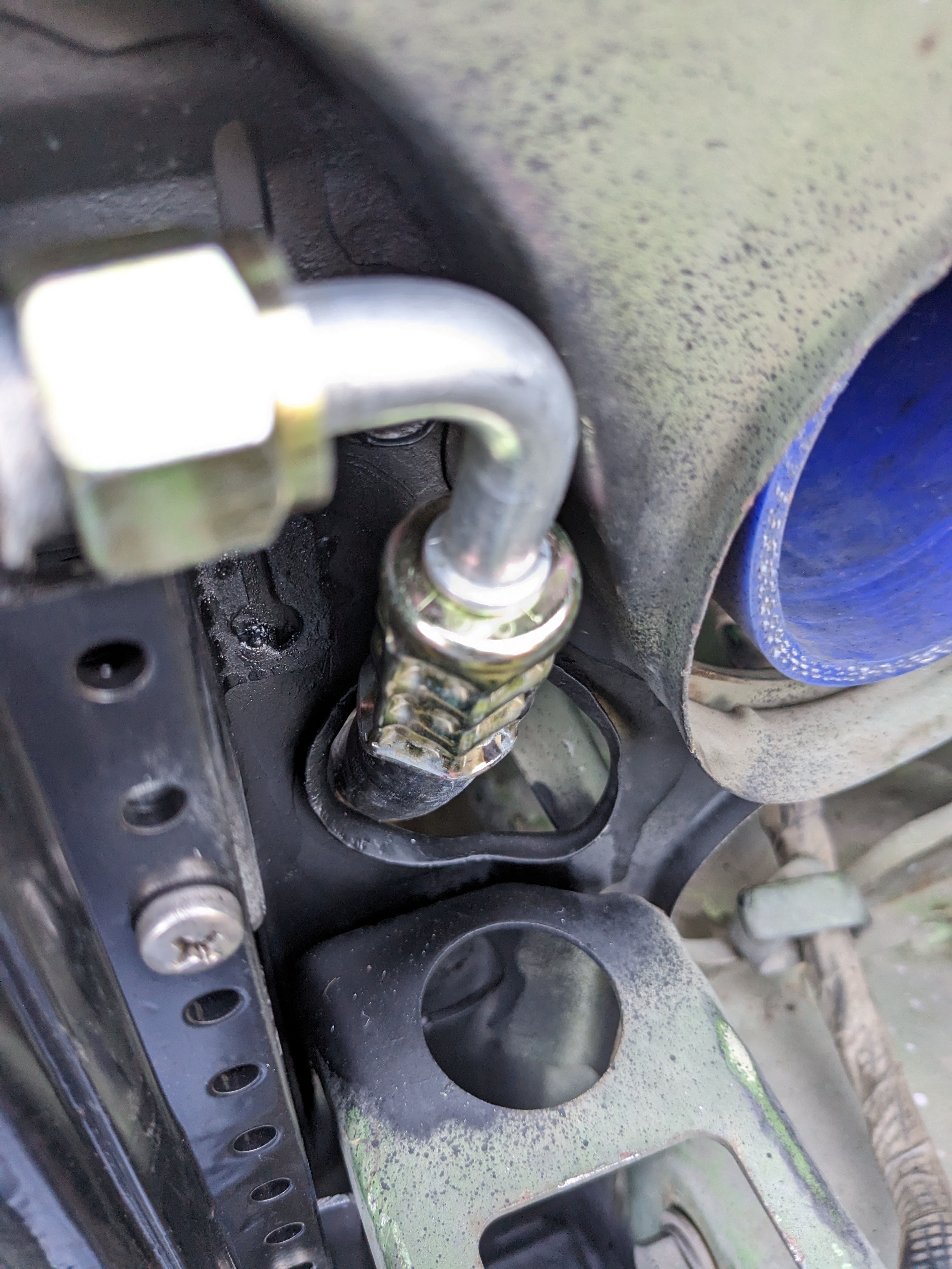
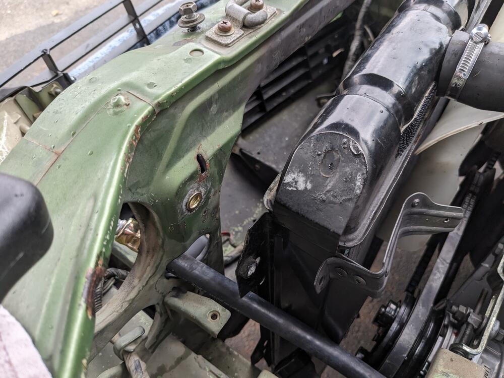
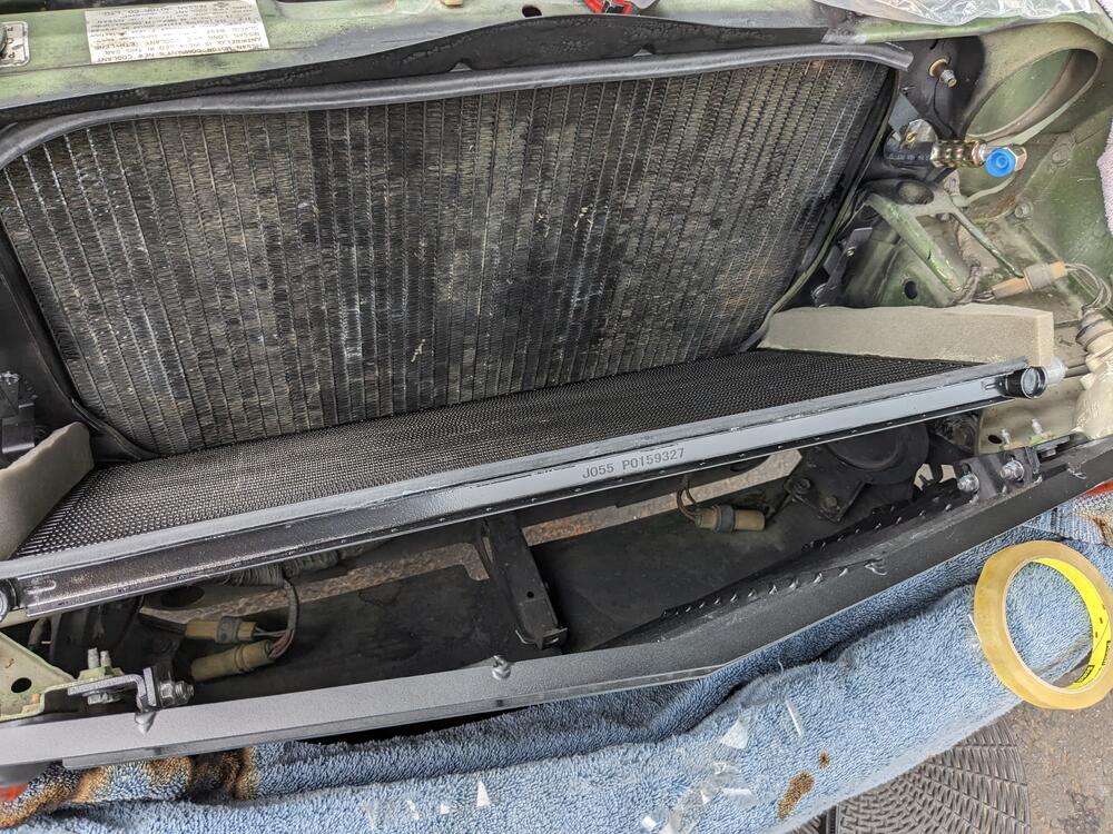
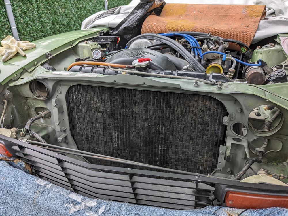
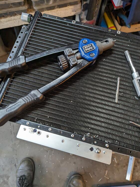
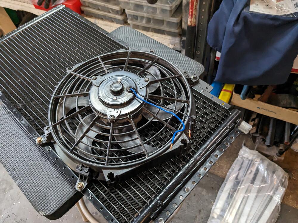
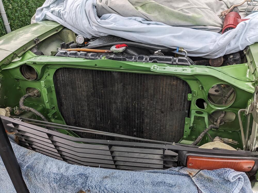
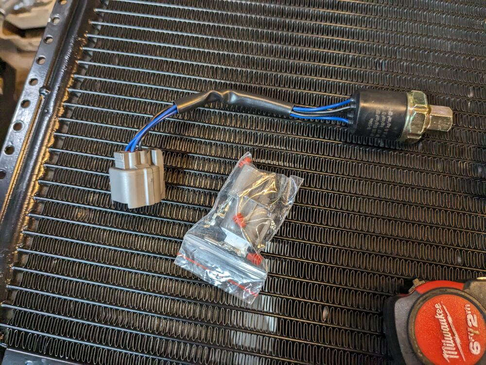
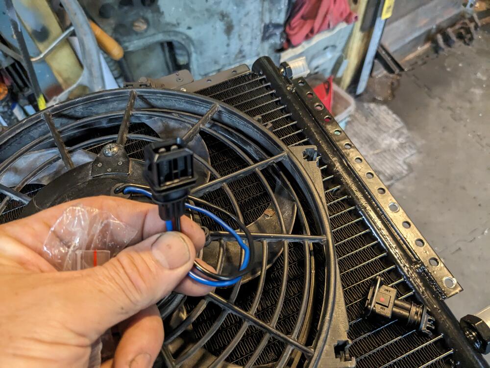
Much rain today, so only small amounts accomplished First, I had to deal with the upper left rad mount. With the AC high side line placed directly in front of the bolt, there would be no access for rad removal without discharging the AC. Not a good plan, pretty much guaranteeing Murphy's Law will strike. So, I drilled out the rad fixed nut, and added an M8 rivnut to the bulkhead, so that one bolt is accessed from the bay. Did mean I had to remove a bunch of stuff to get the rivnut tool in there. Figured out the condenser to rad sealing. Foam on the verticals, rubber seal along the horizontal lip. Had enough of a window to prep, prime & then later paint the nose panel, before I get everything back together. After that I worked on mounting the AC fan to the condenser. I previously used 2 of these on my X1/9, they don't flow the claimed CFM, however it's enough for this purpose, and this will also go away with the V6 conversion anyhow. Added M5 rivnuts to secure the fan. Had to add an additional plate to make it work. added waterproof AMP/TE connector, 2.3mm terminals also wired the Trinary switch, used a Sumitomo 4 pole connector here
-
I'll take a deeper look through your thread, looks like you are going whole hog on that!
-
Hello Matthew - Loved the bracketed you worked up for your HVAC install, very clean work! Couldn't see any pics with wiring, but that's OK. In my case it's not one wire as with the original setup, as there is also a Trinary switch added that is used for high press cutoff. I didn't mention it, however I'm also adding a Volvo (Bosch) Constant idle speed system they used back in the 80's with K-Jet V6 applications, prior to using Bosch LH2.xx systems. That requires approx 11 wires to pass from the cabin to the intake.
-
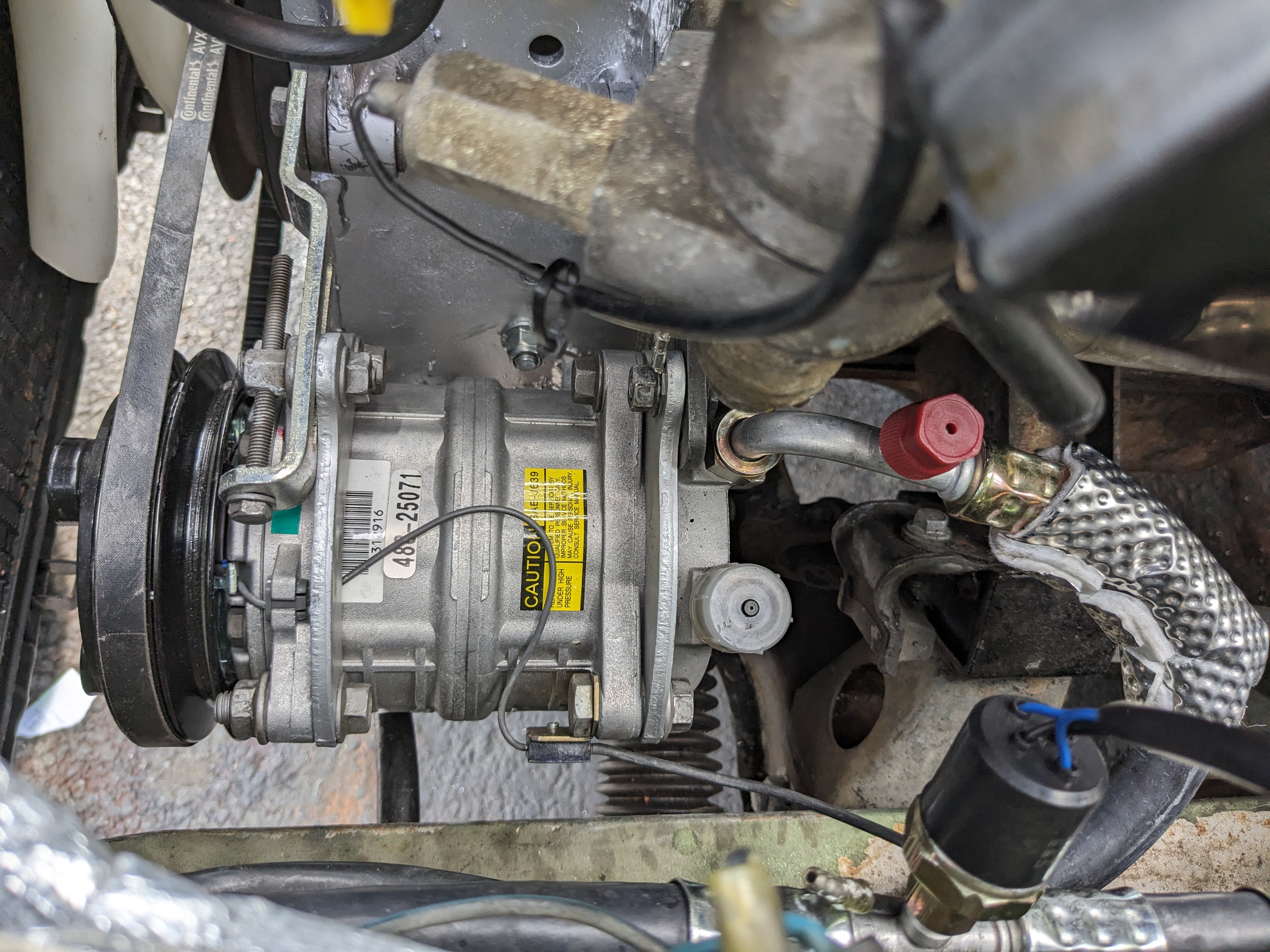
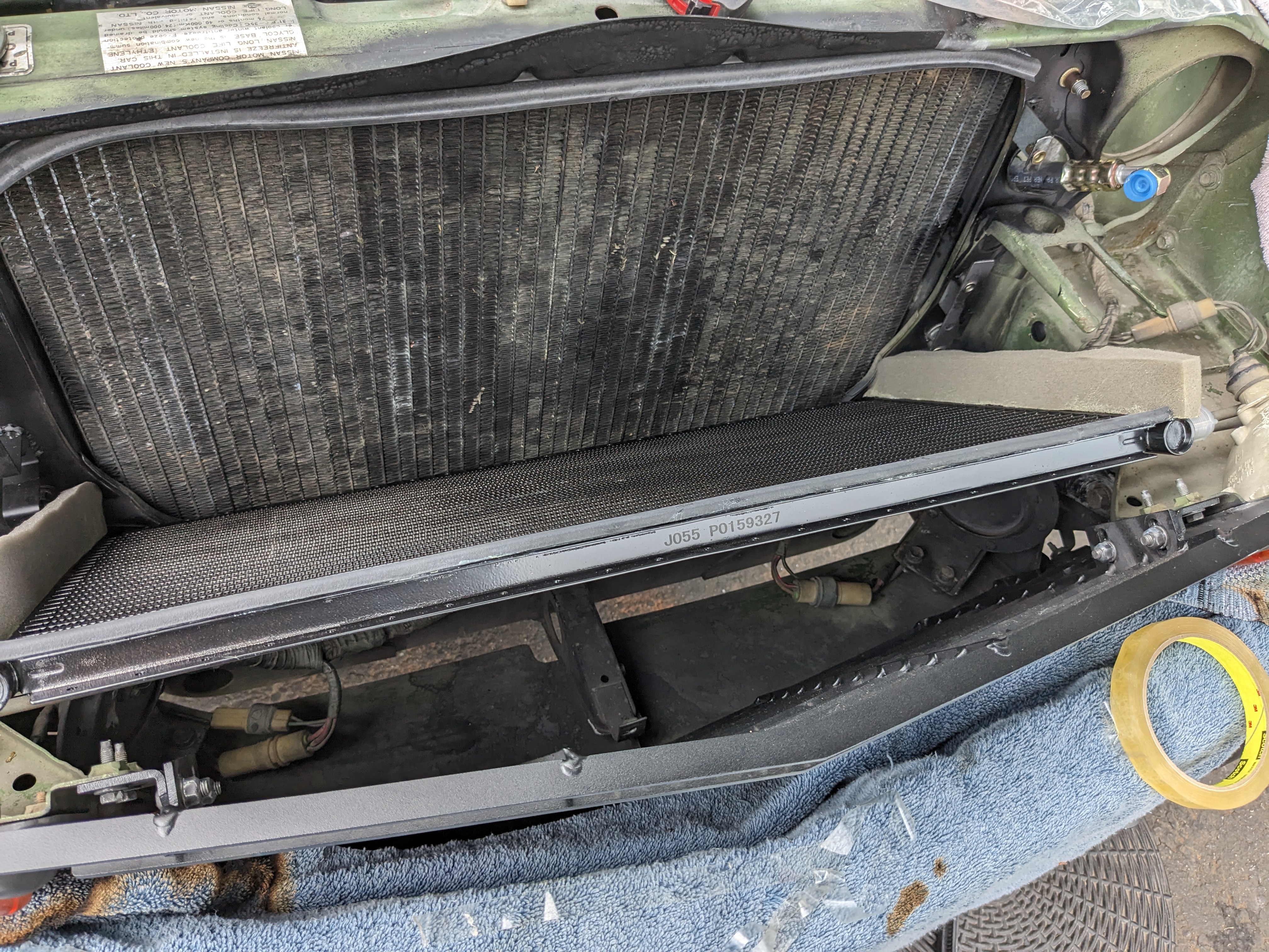
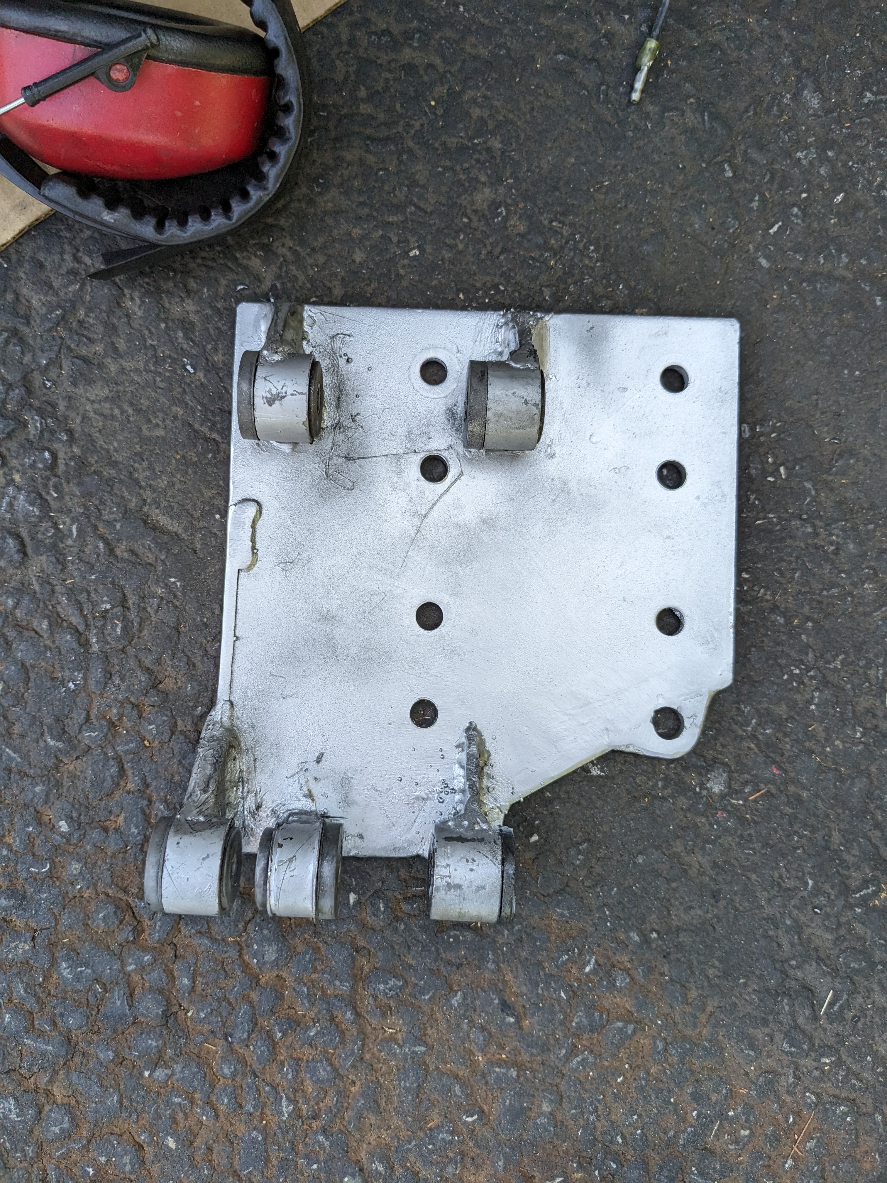
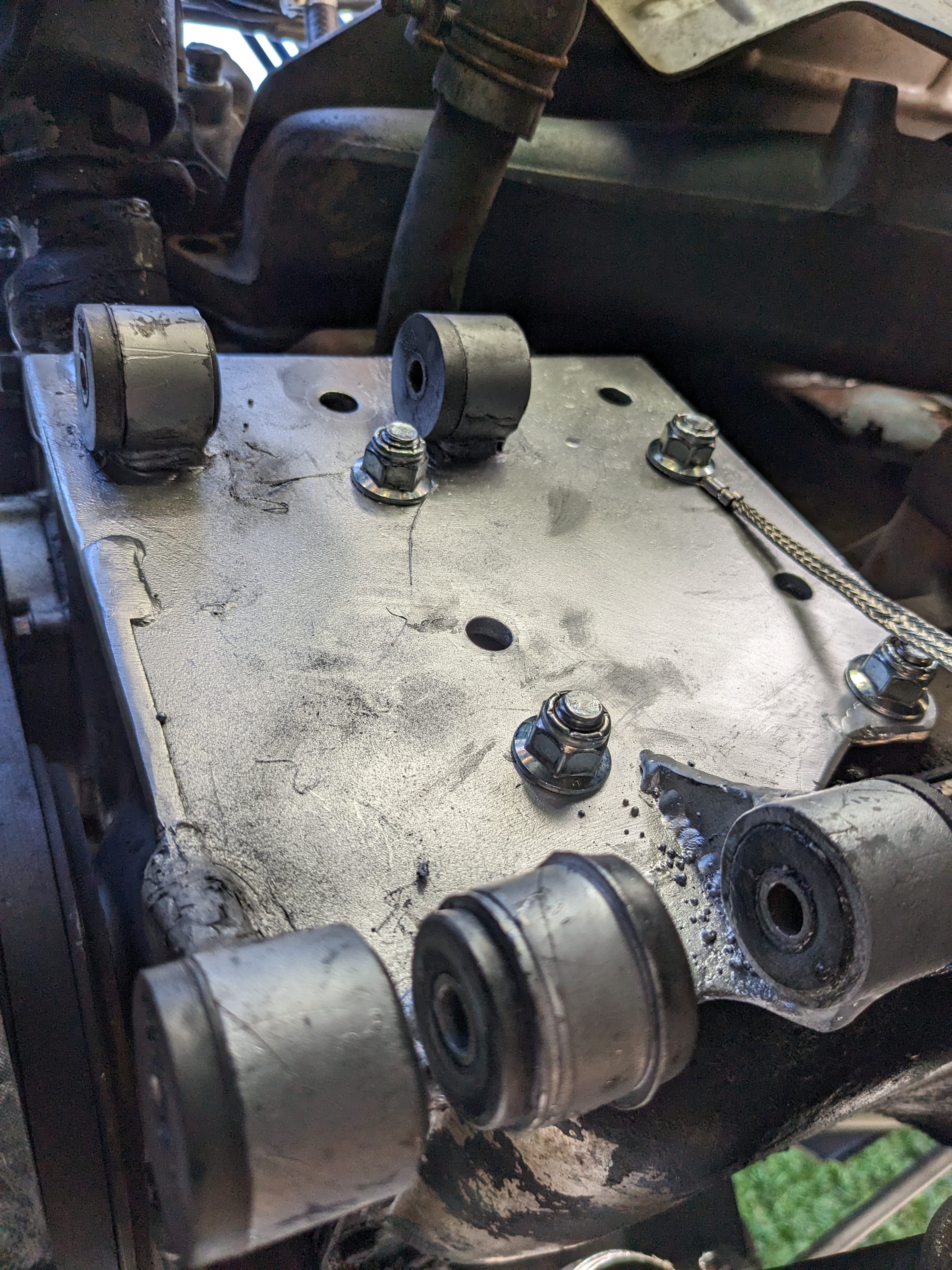
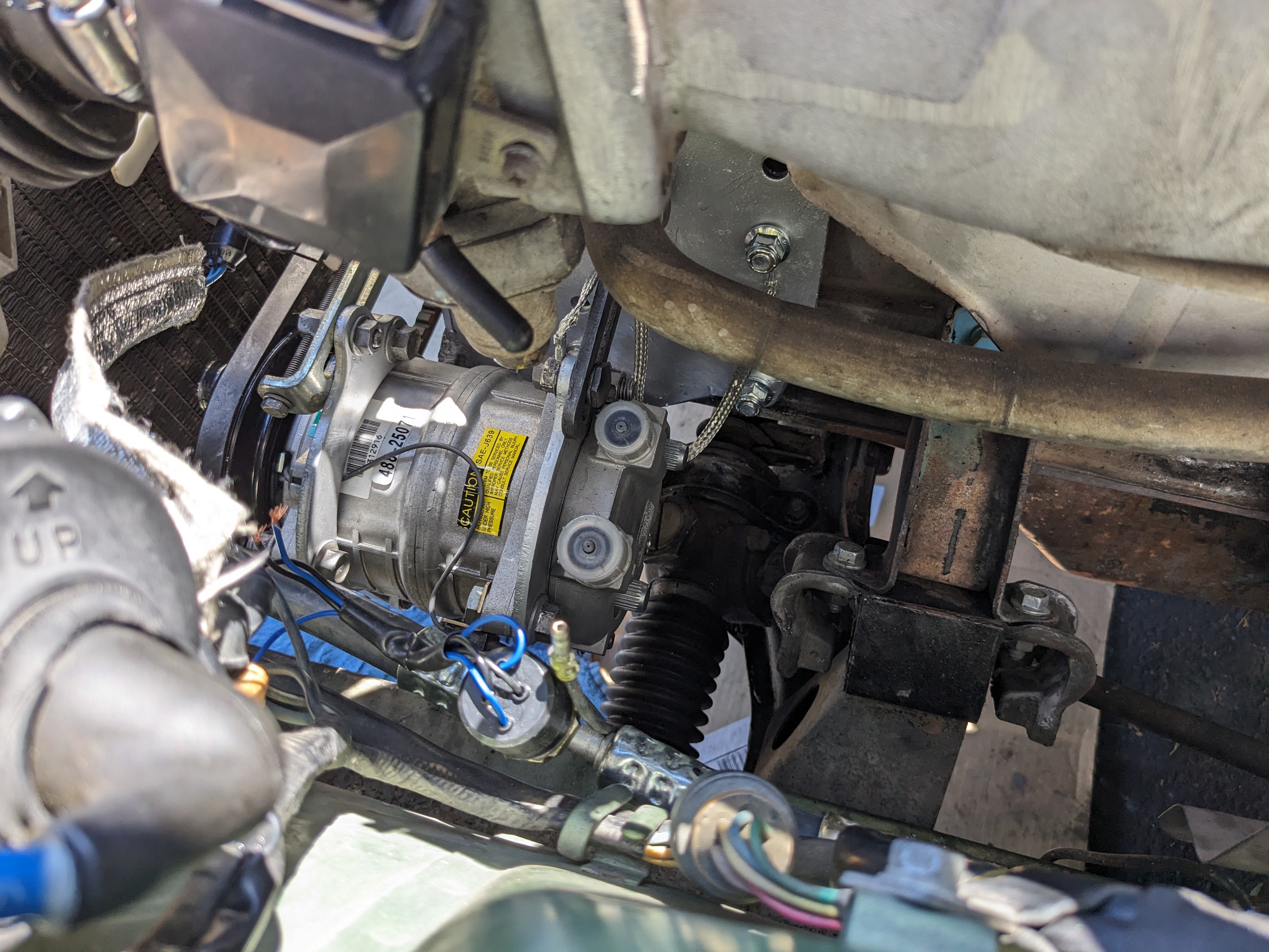
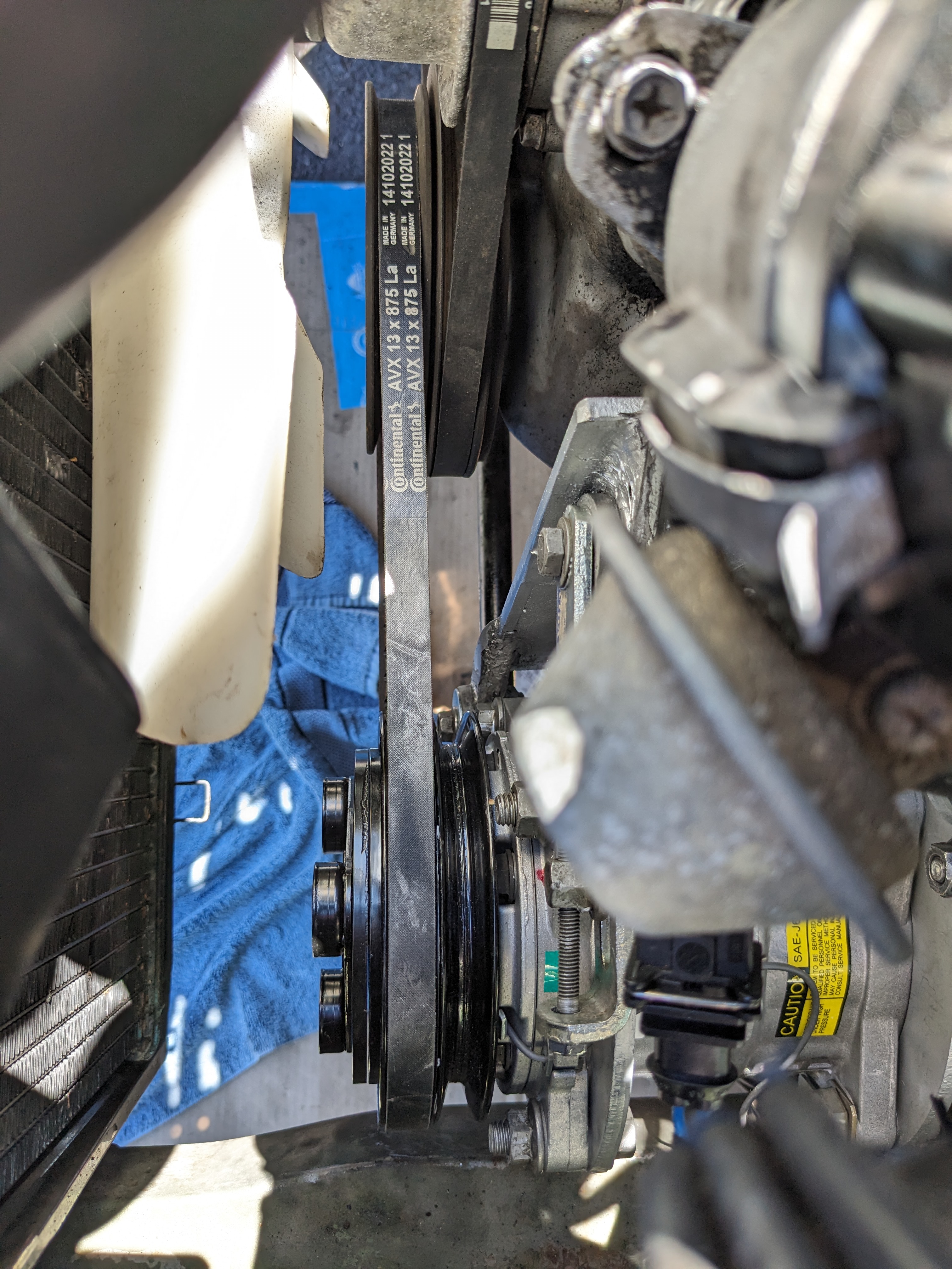
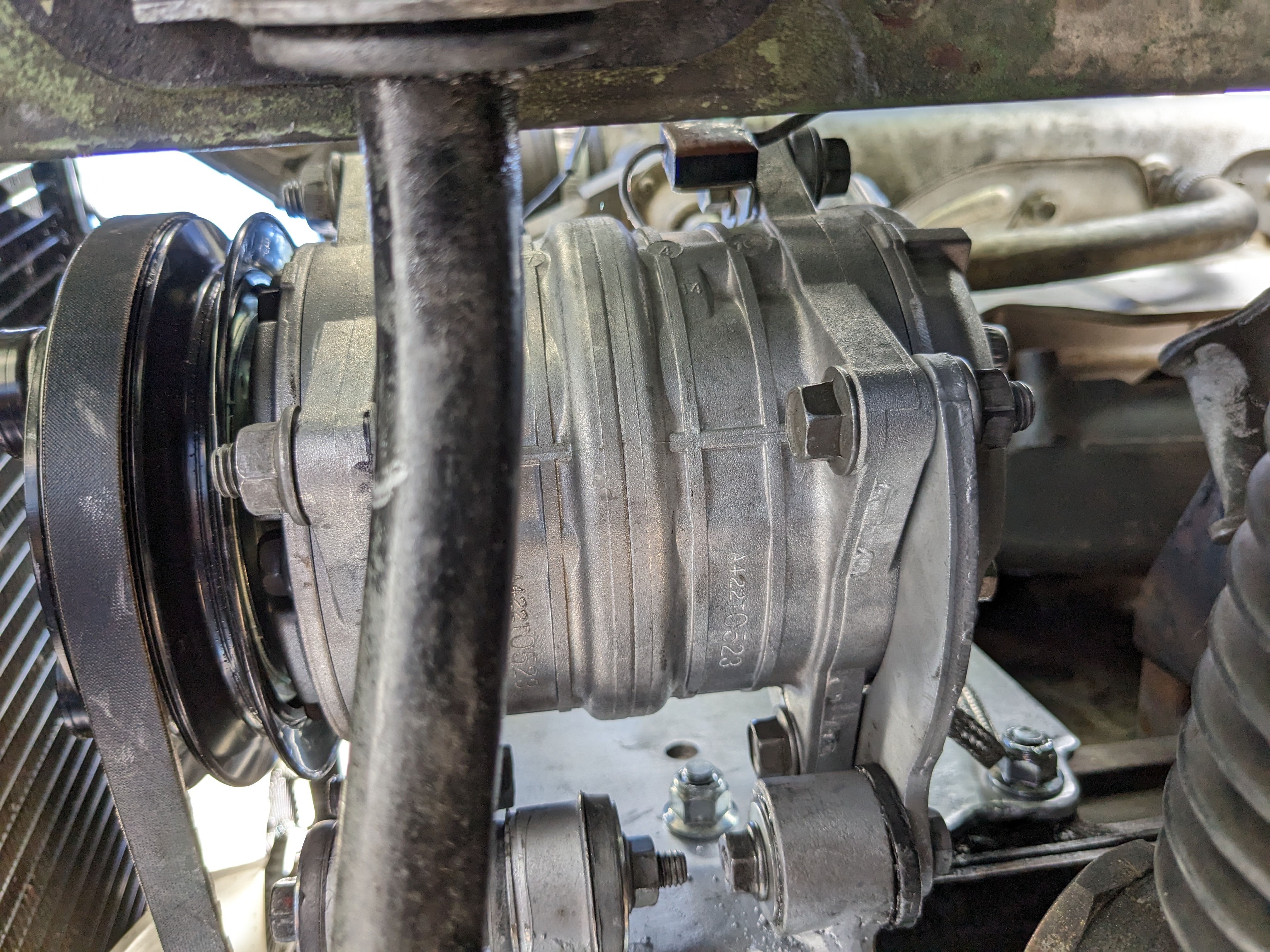
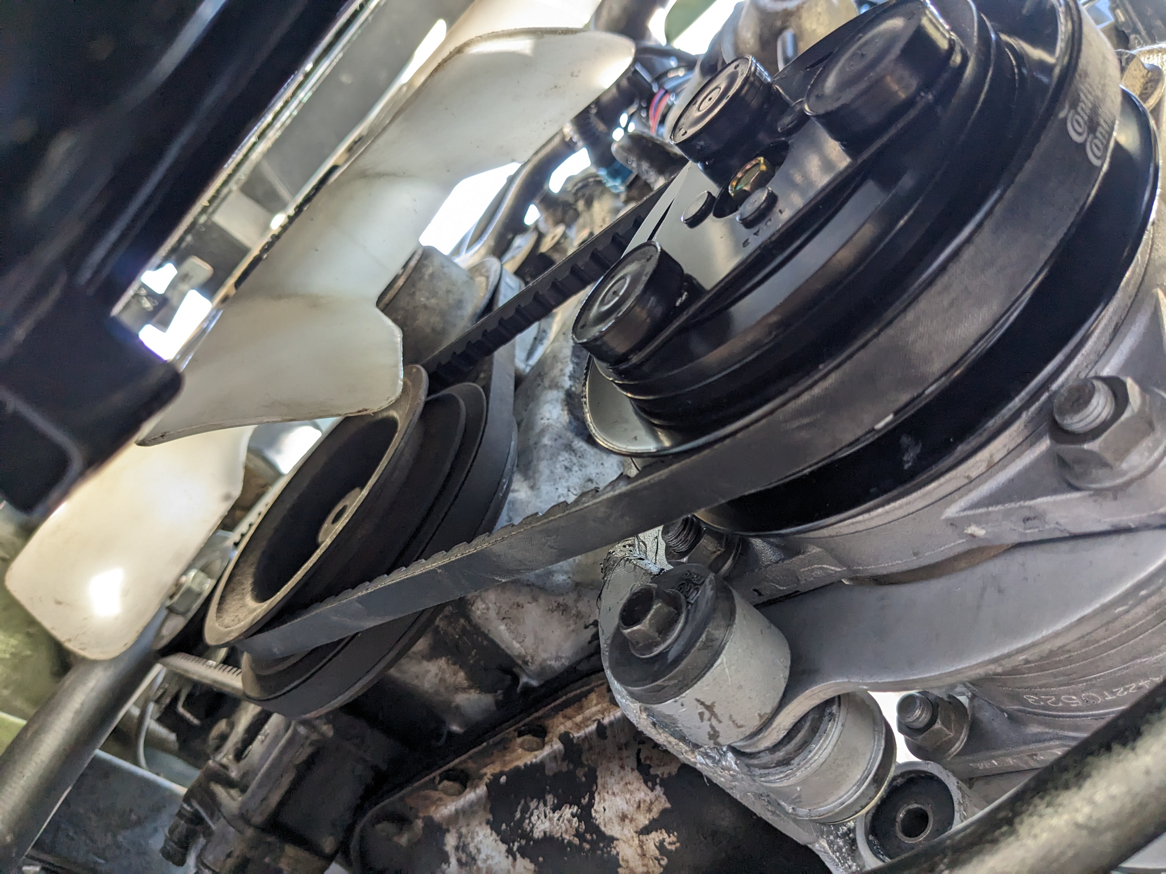
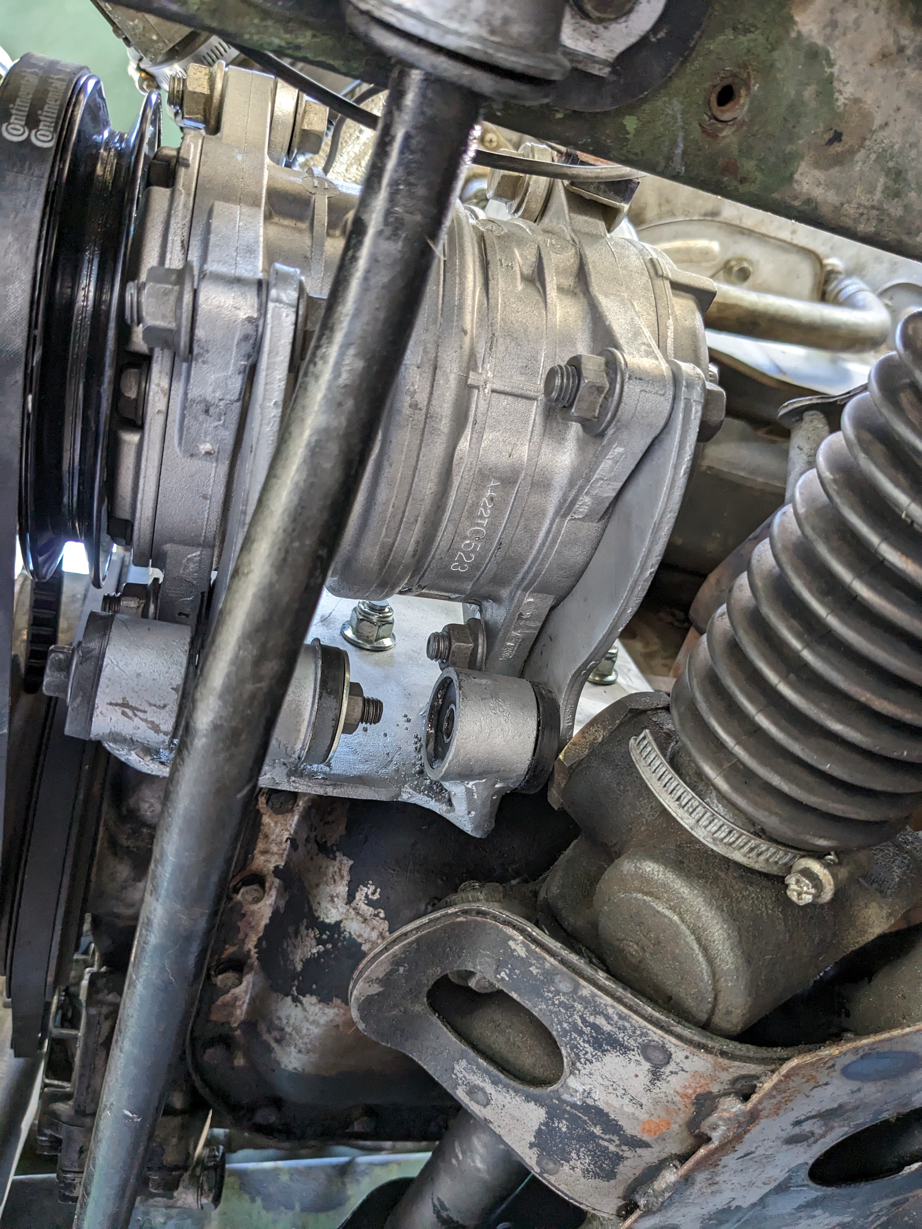
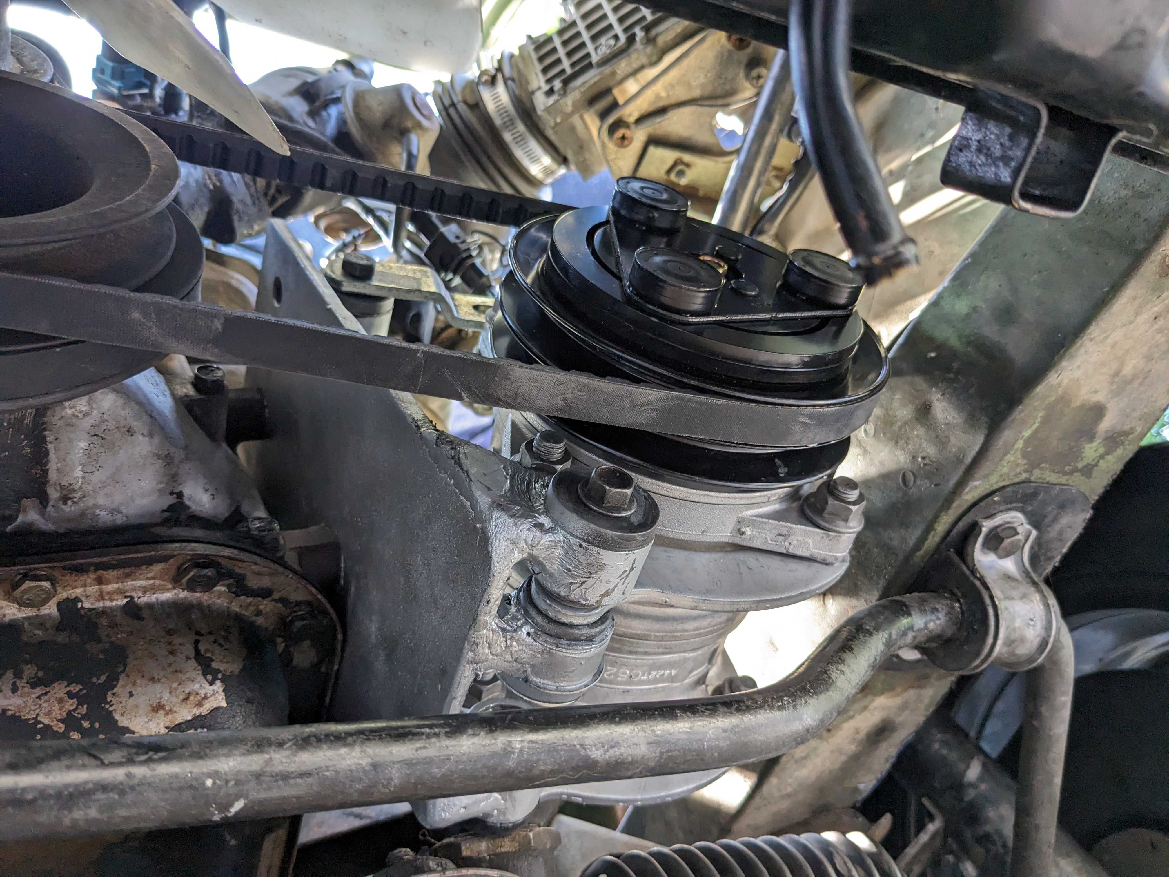
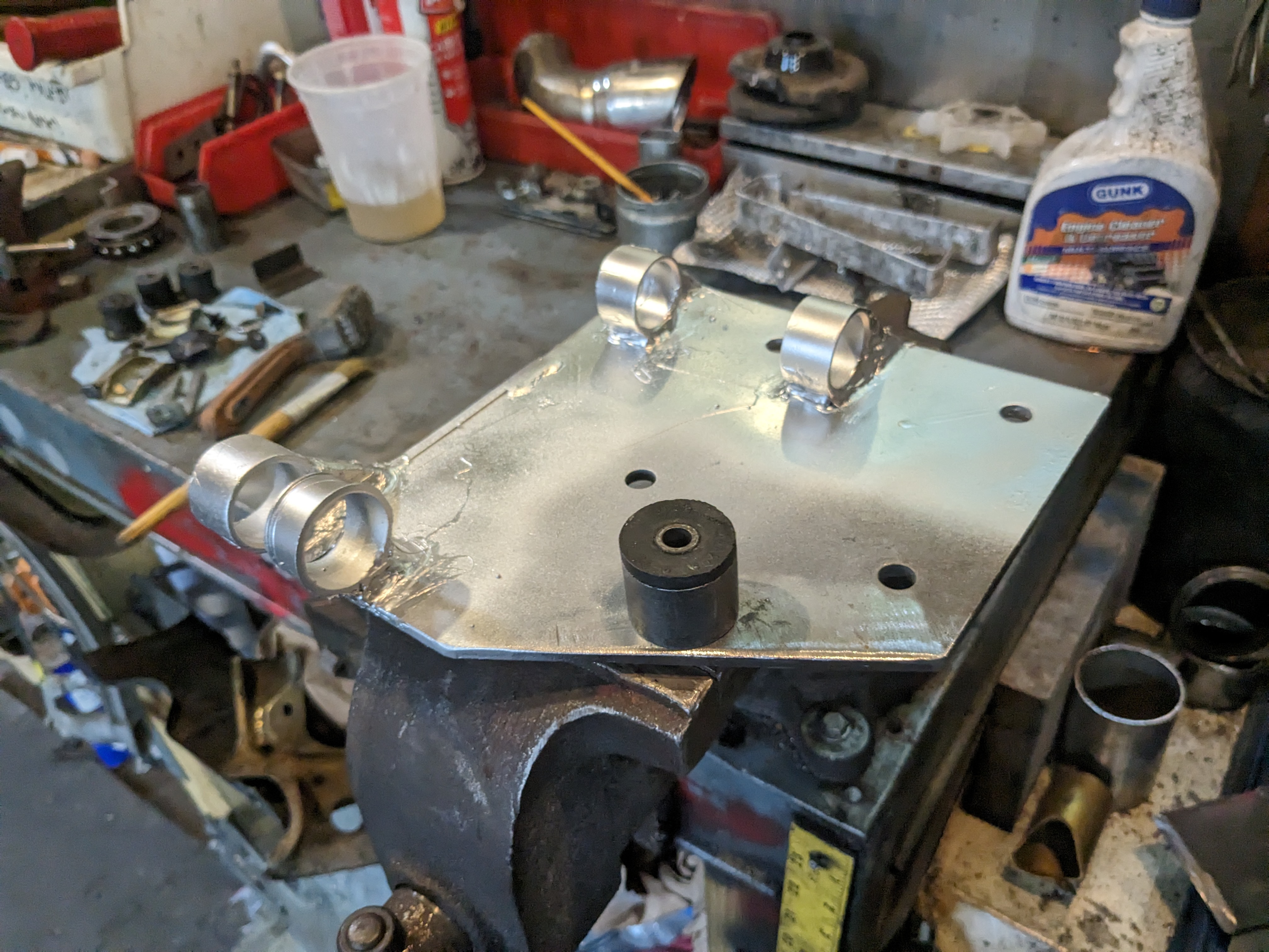
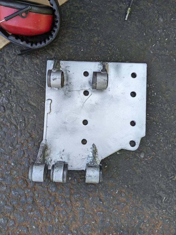
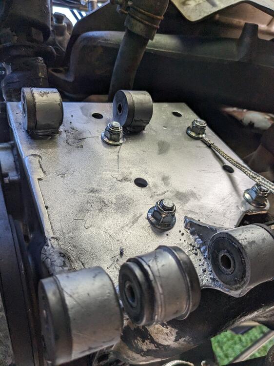
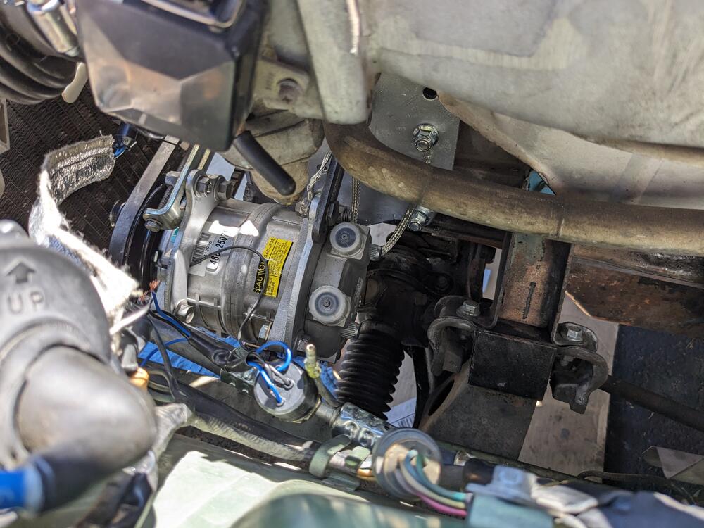
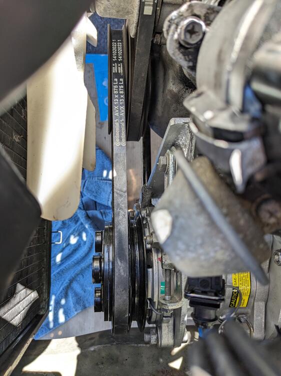
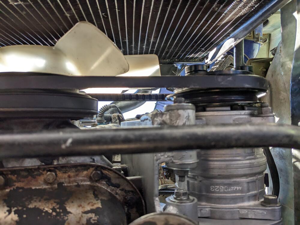
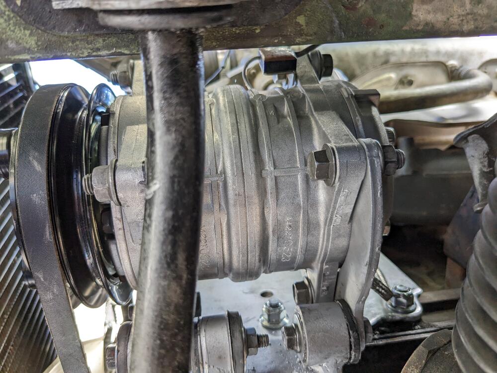
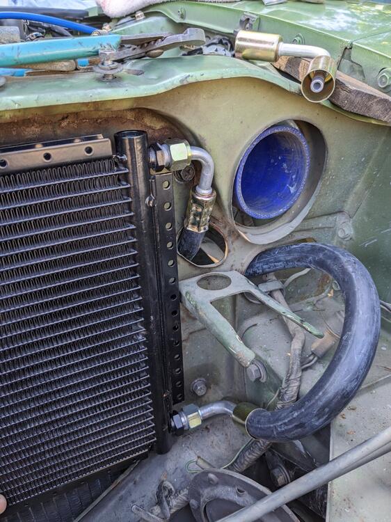
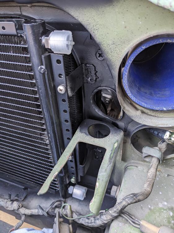
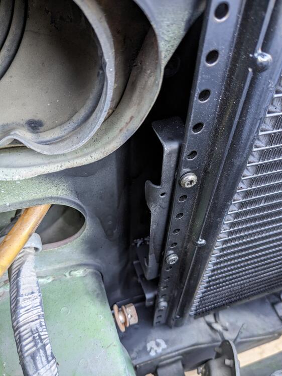
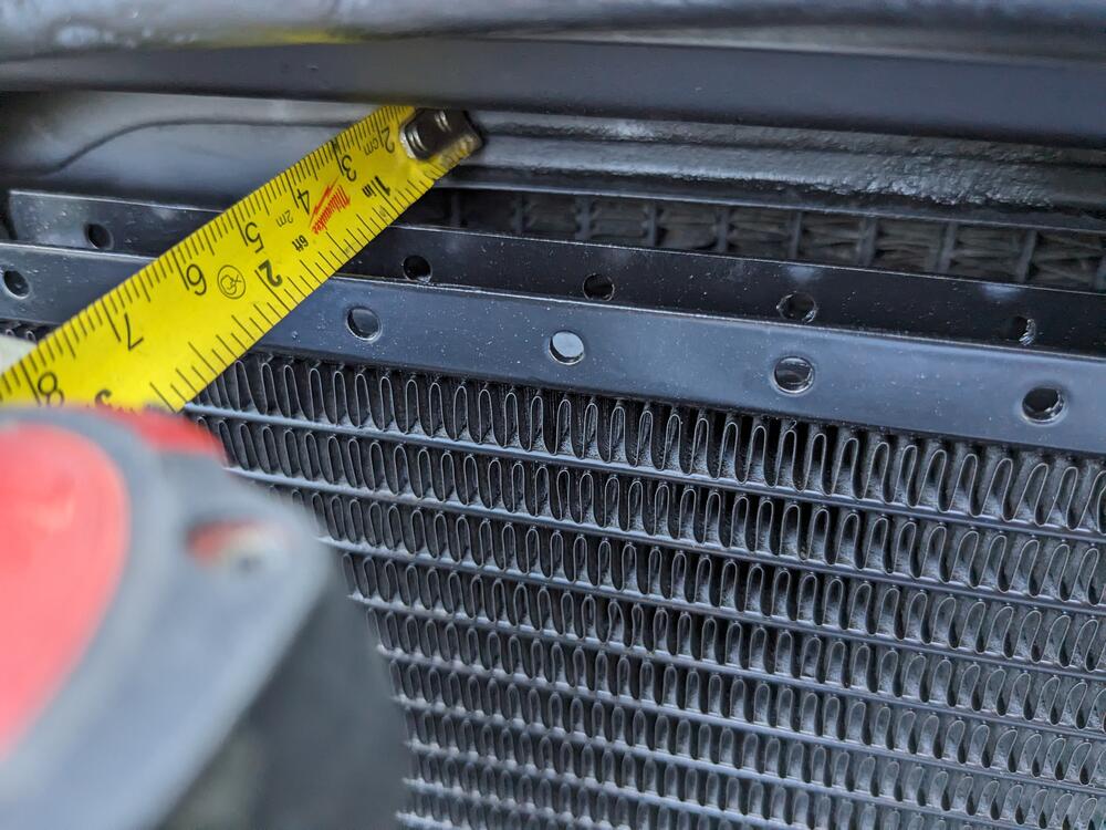
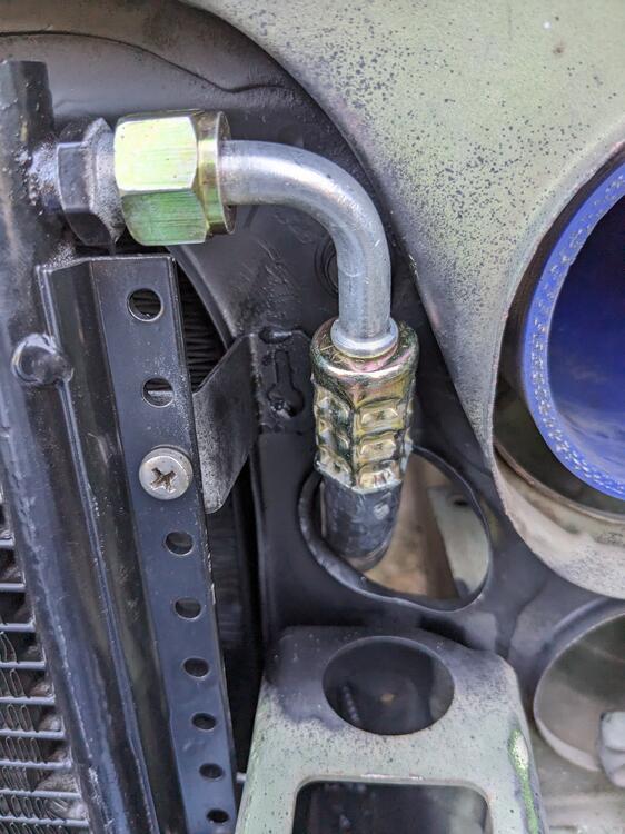
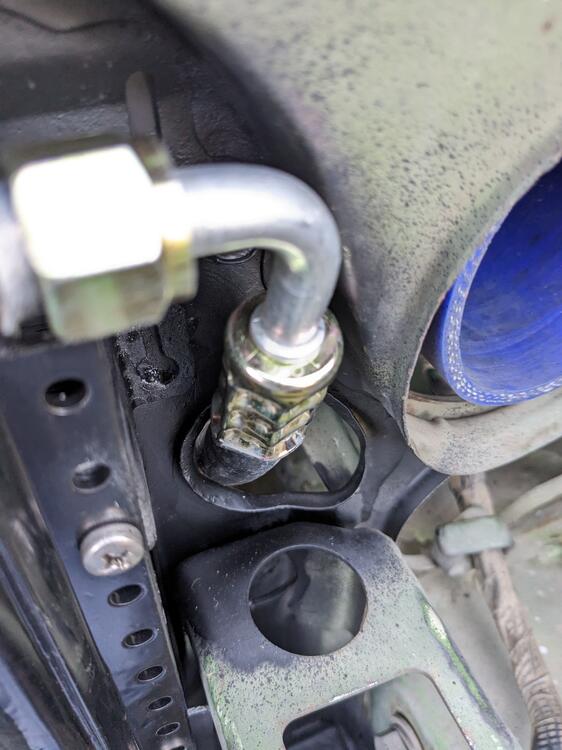
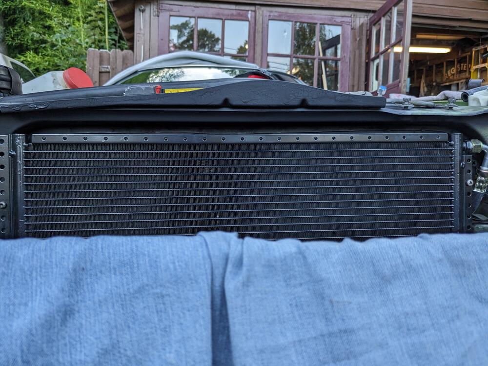
reworked the mount plate, set all holes 1.5" below original; had to add an ear for the rear lower mount point. back in place, with earth strap for compressor compressor in place. Belt could be 25mm shorter, but still have enough range as it is belt alignment and clearance all around looks good With that aspect done, I worked on the condenser mounting & high pressure hose fitting. Low press hose will be shorter made standoffs (set 1.5" off the bulkhead) to secure the condenser, one with 3 M4 screws on the right, 2 separate ones one the left; upper with one screw, lower with two. about an inch along the top. I will make seals to fill the space along the top, and down the sides of the condenser. rolled the lip in the bulkhead to make sure the high side line doesn't chafe
-
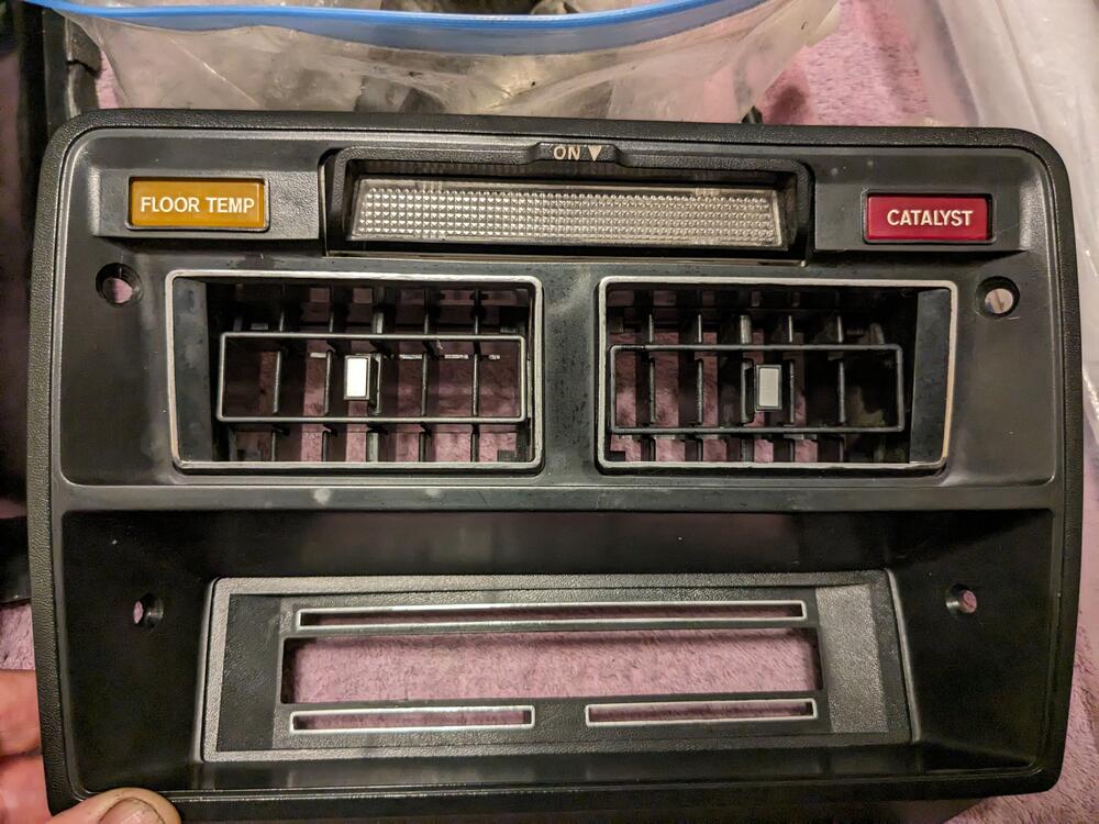
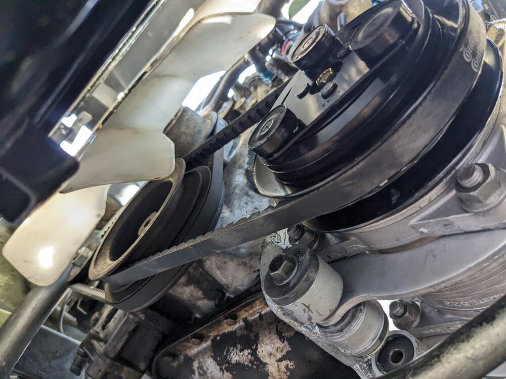
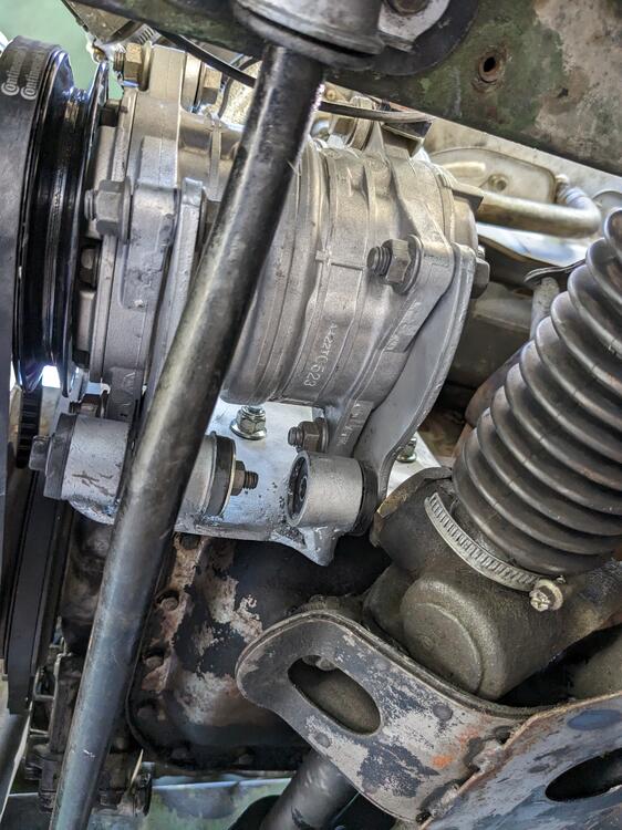
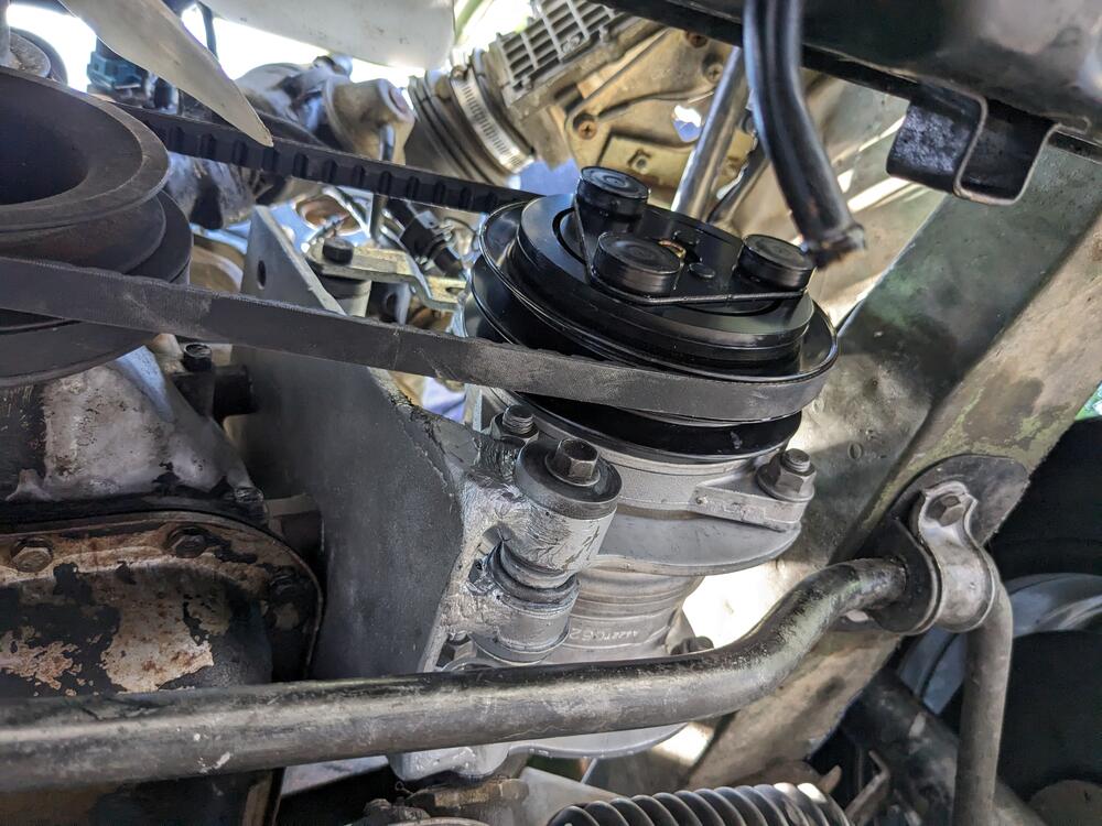
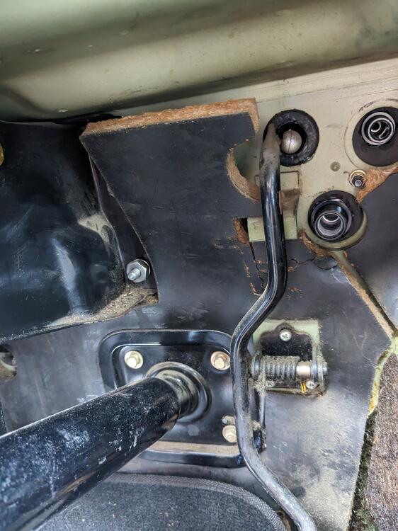
Touched up the silver edging Test fitted the compressor & mount. It will have to be raised age least an inch. Rear lower mount sits on PS rack. Stock Datsun AC belt length will be OK (13x875). Have to figure out the best place to drill through for a harness for the AC stuff
-
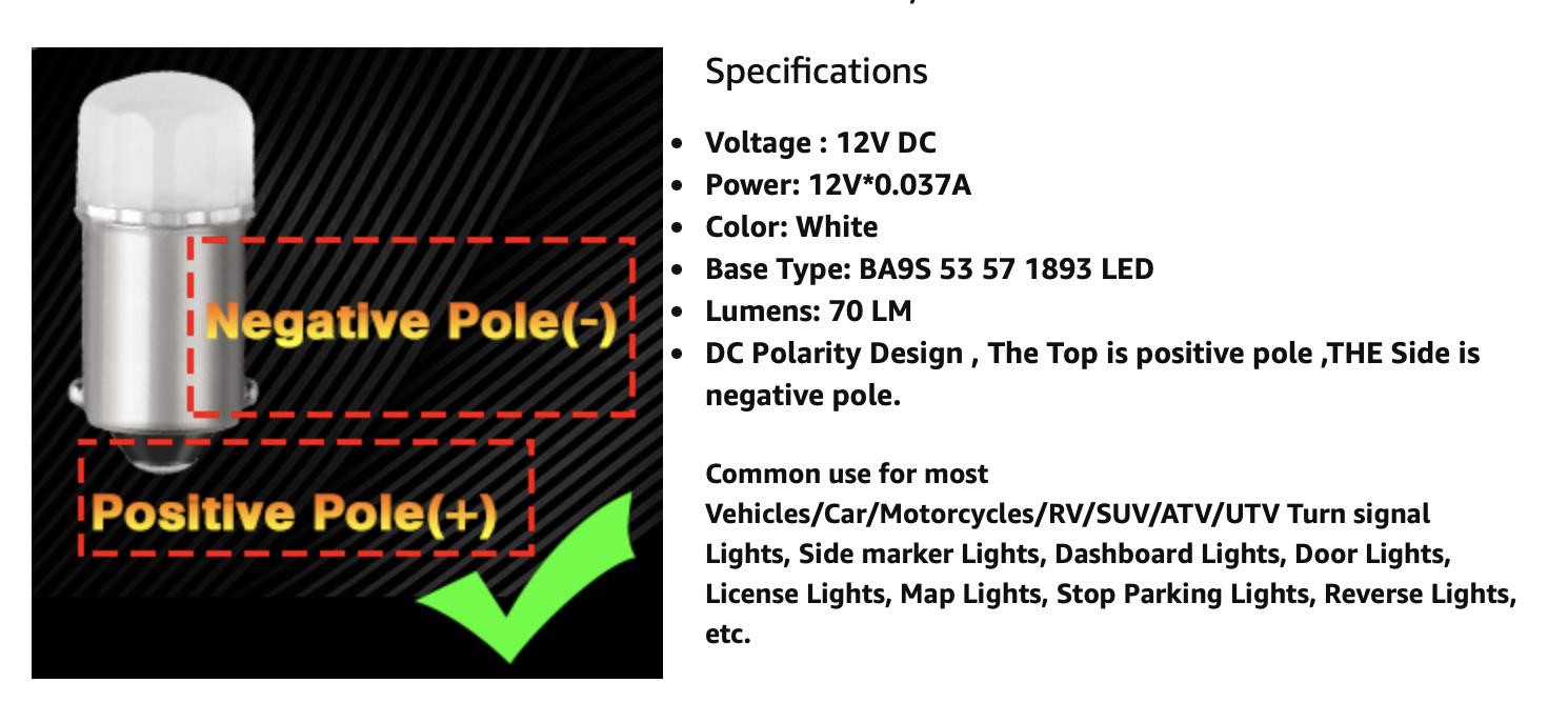
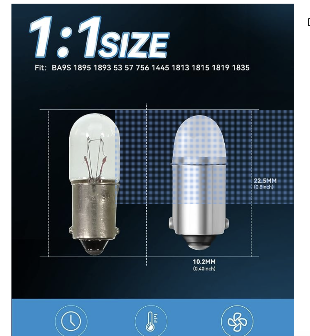
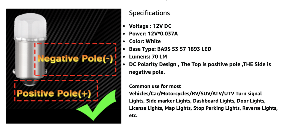
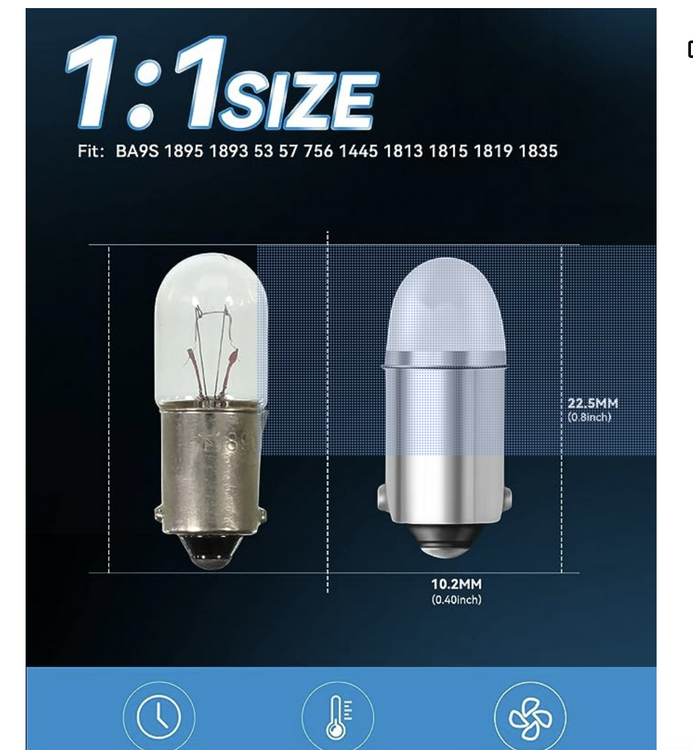
I bought a 10 pack (white) of these today - specifically because they indicate they use the same polarity as a DC bulb, and because you said they work with the dimmer. I personally dislike intensely the extreme brightness of LED bulbs, so being able to dim them without adding an extra circuit that makes them dimmable is essential. The other ones (Kieurot) linked do not appear to be polarized, and appear to be on the long side, based on the pic provided
-
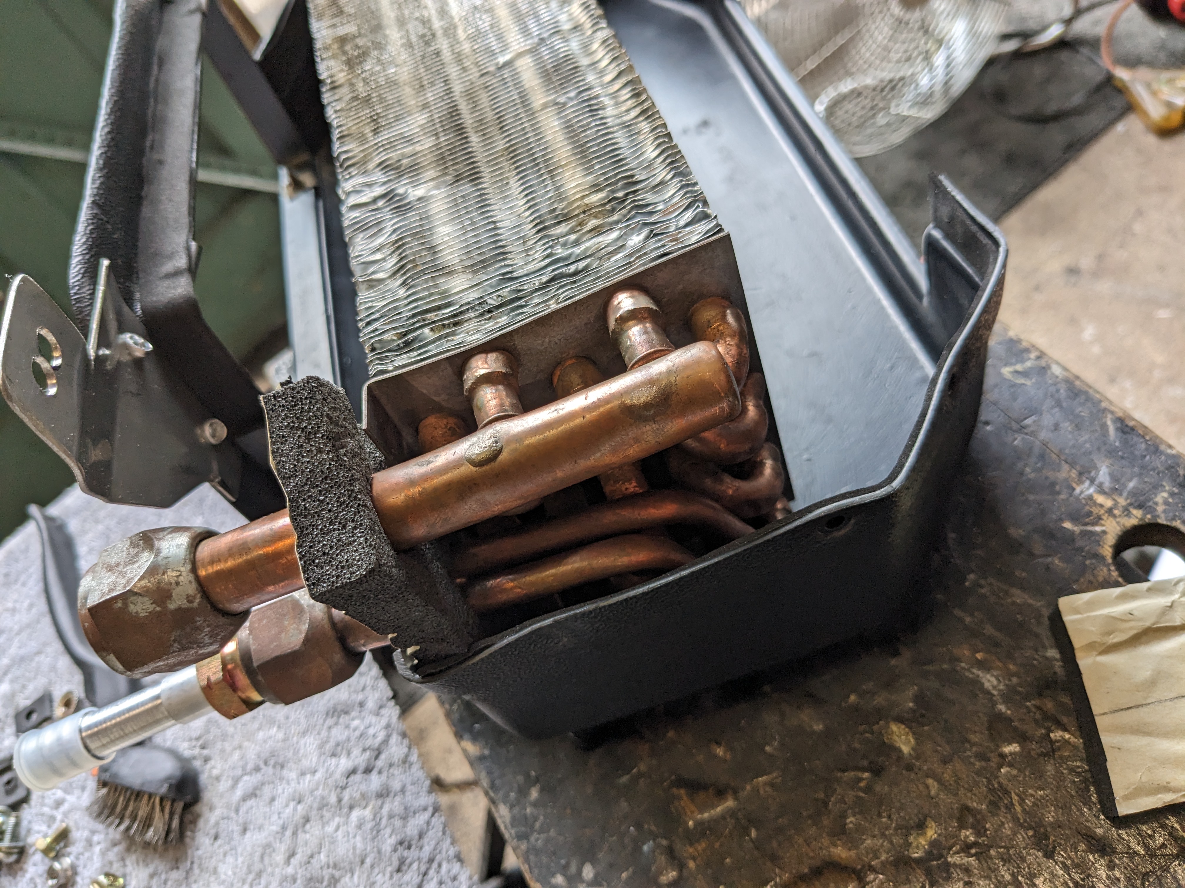
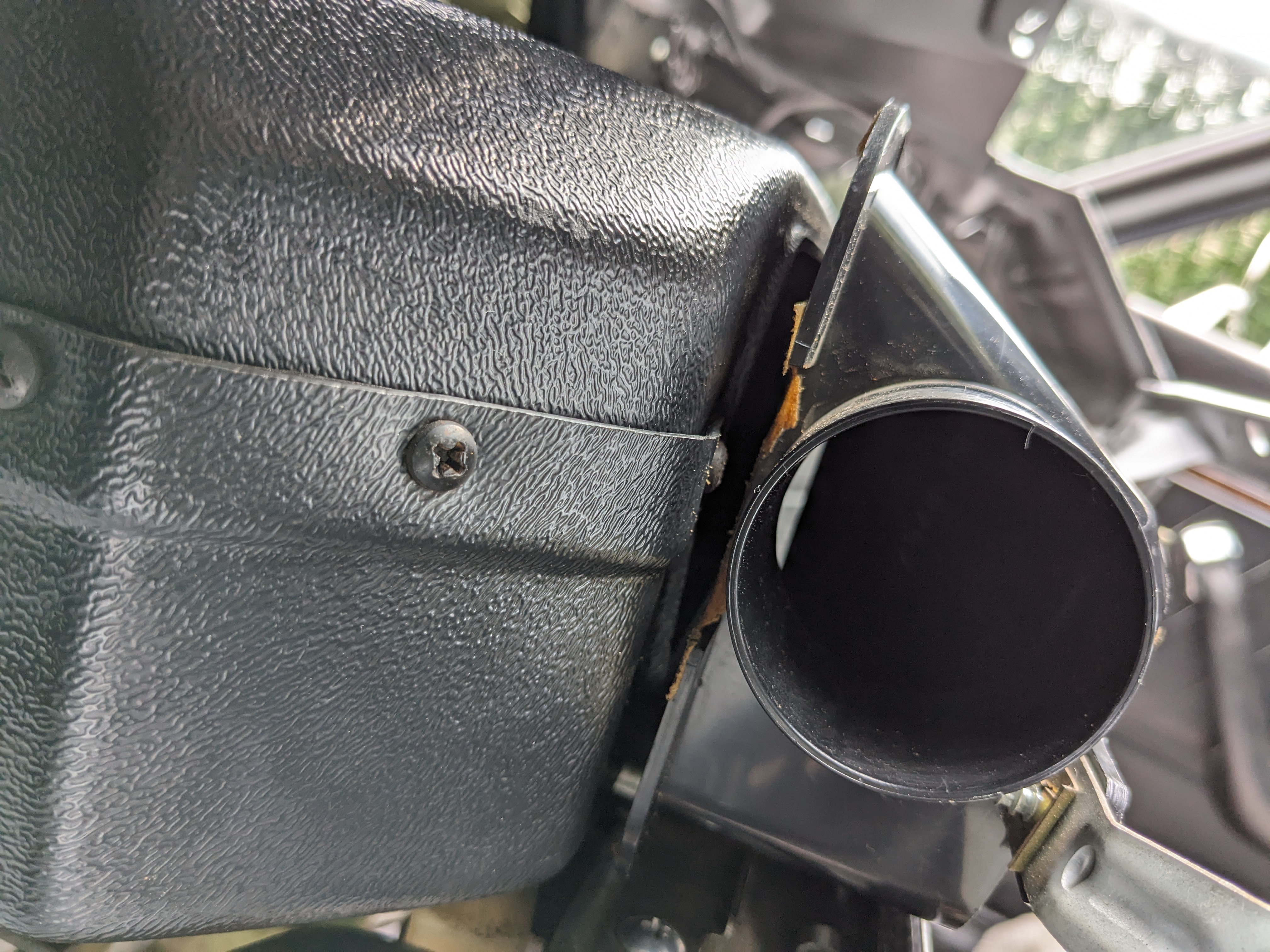
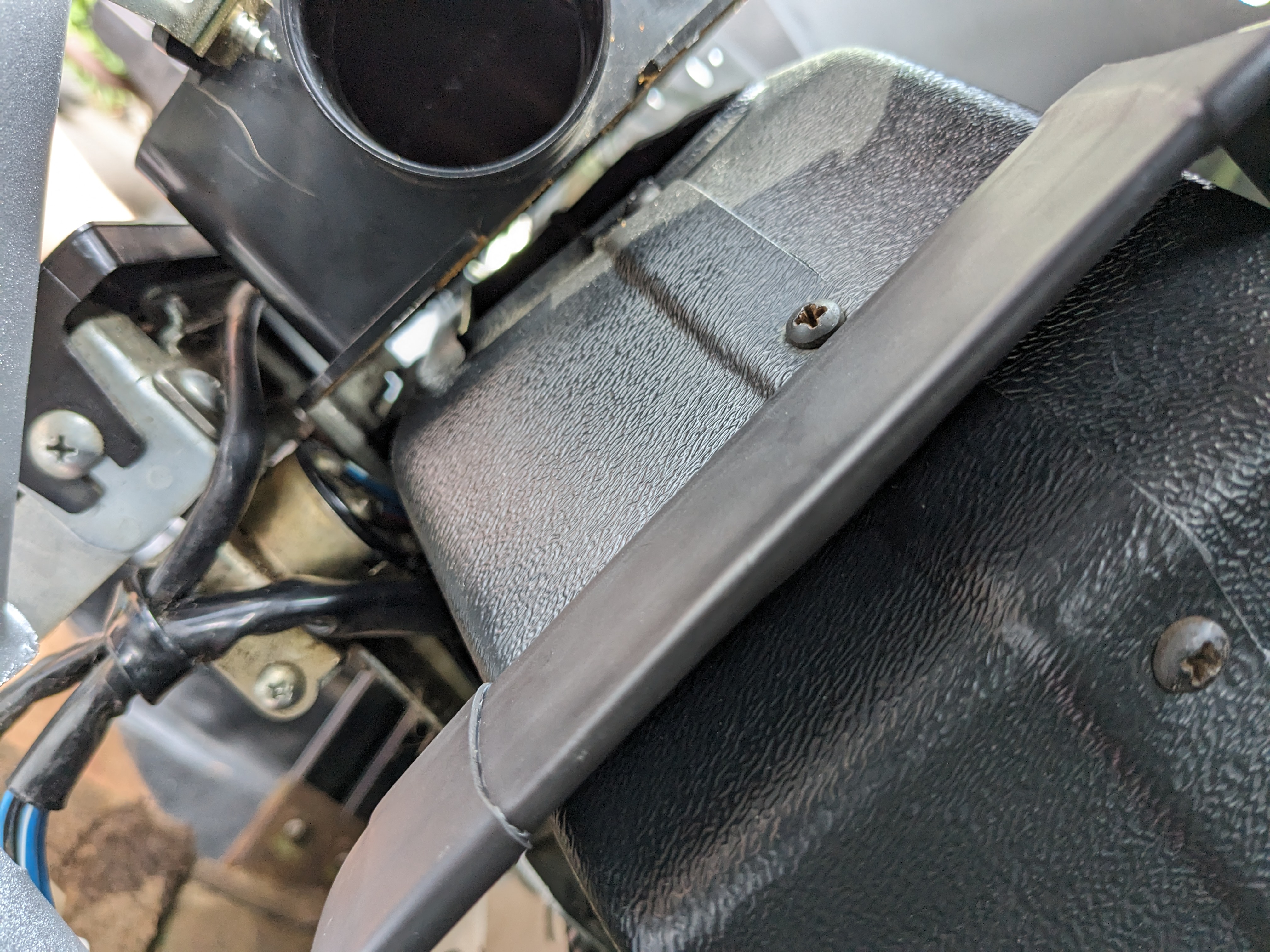
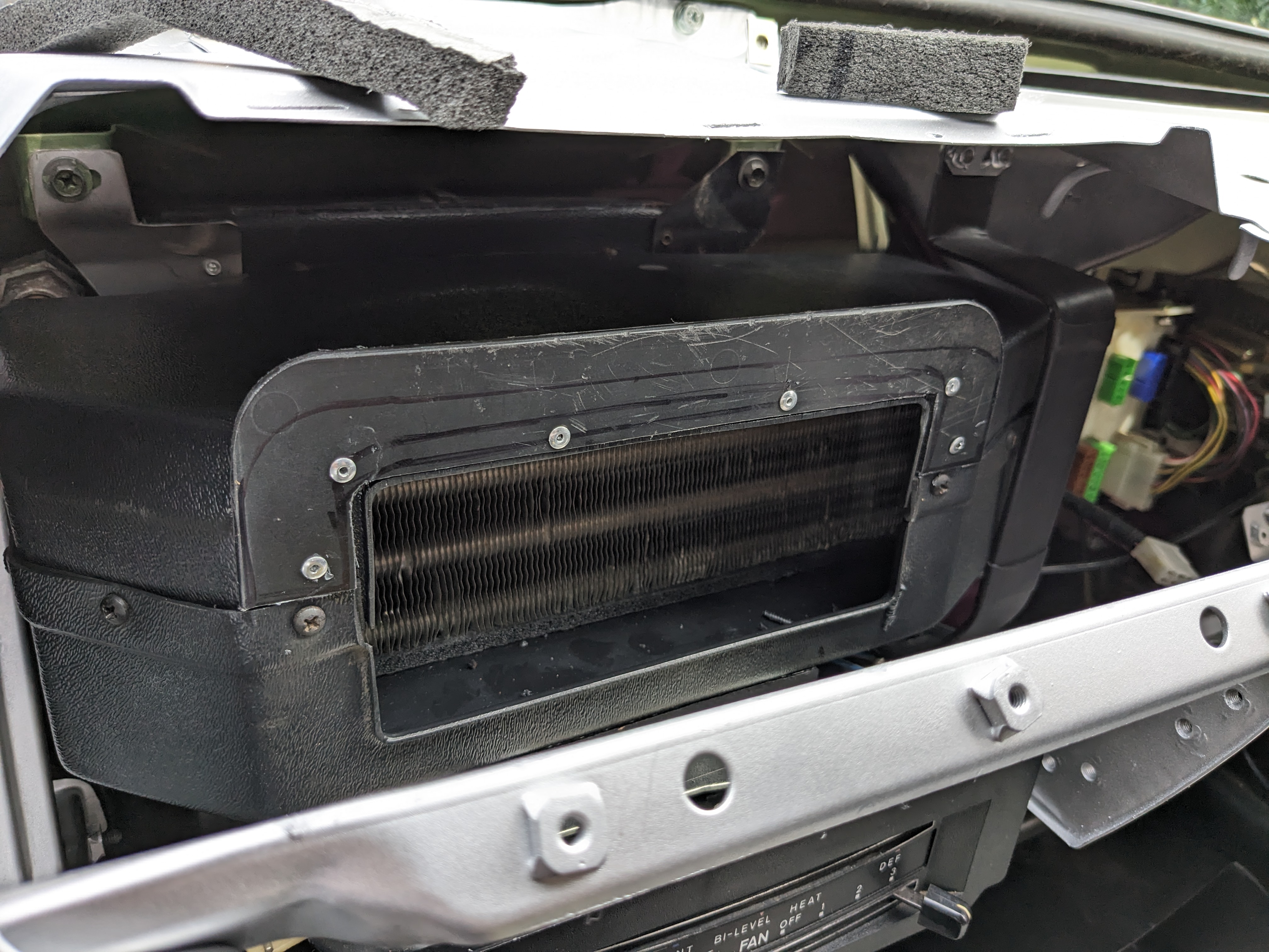
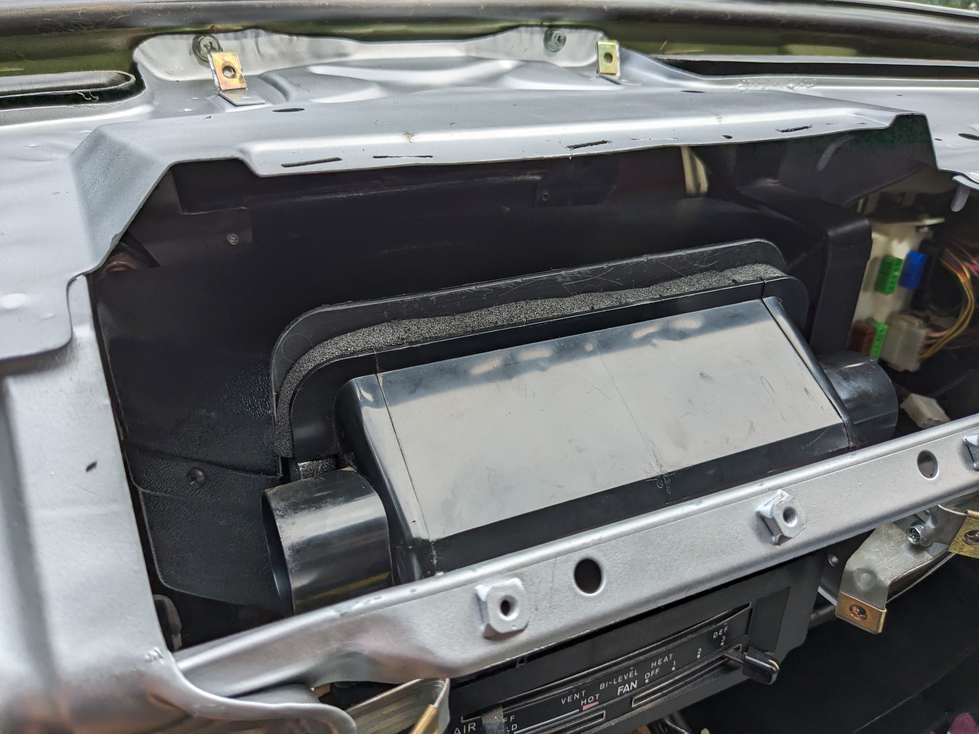
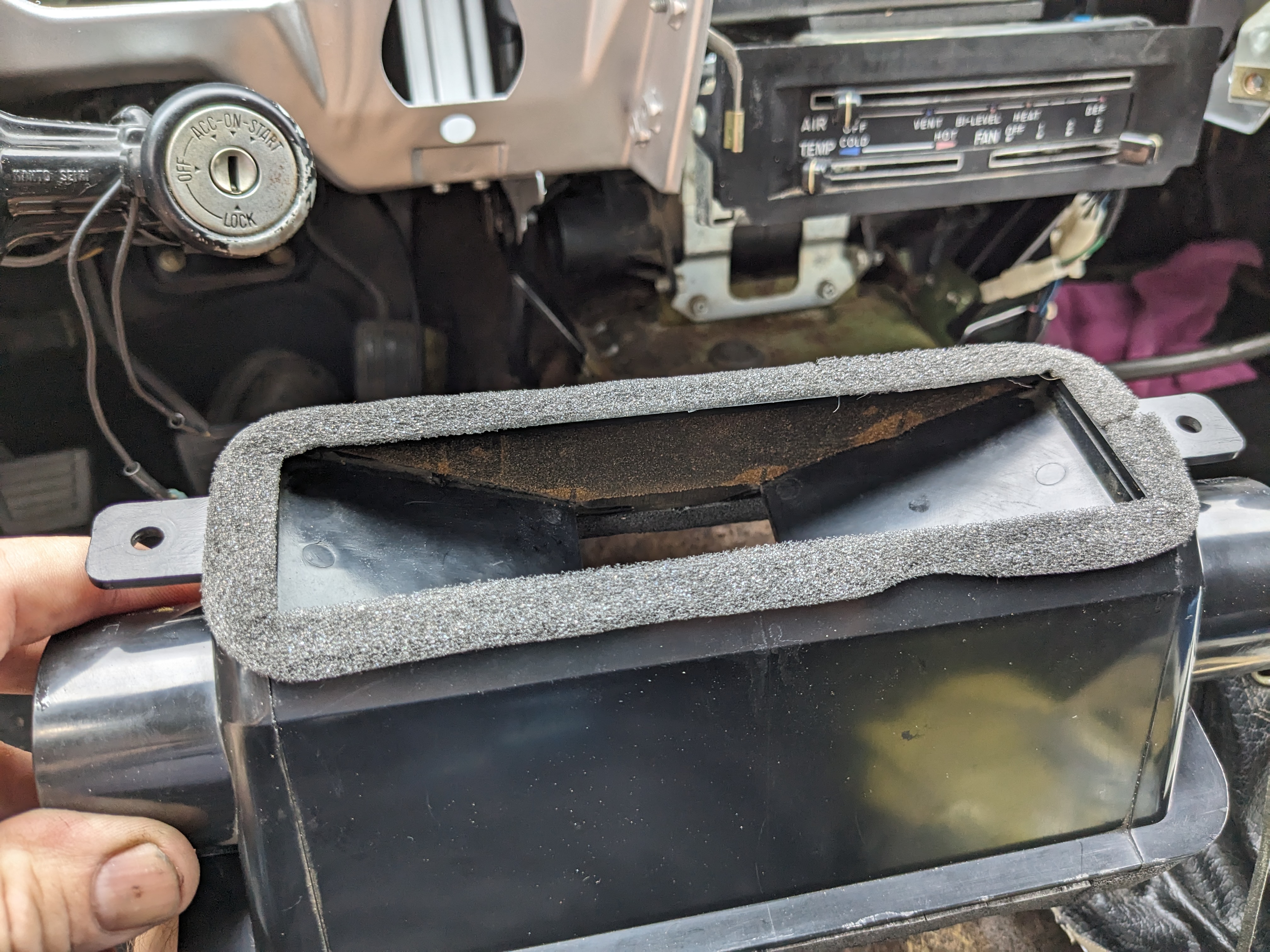
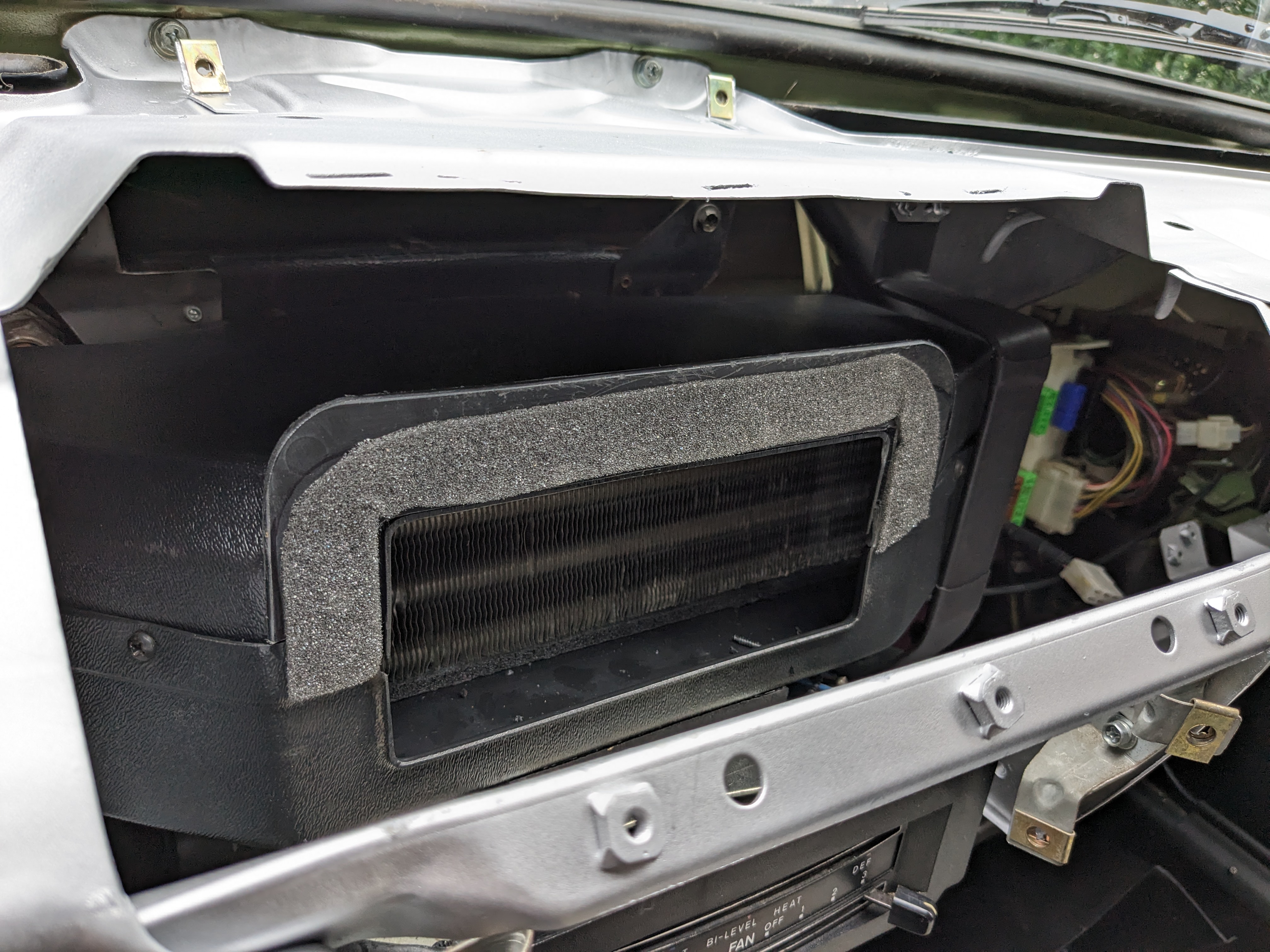
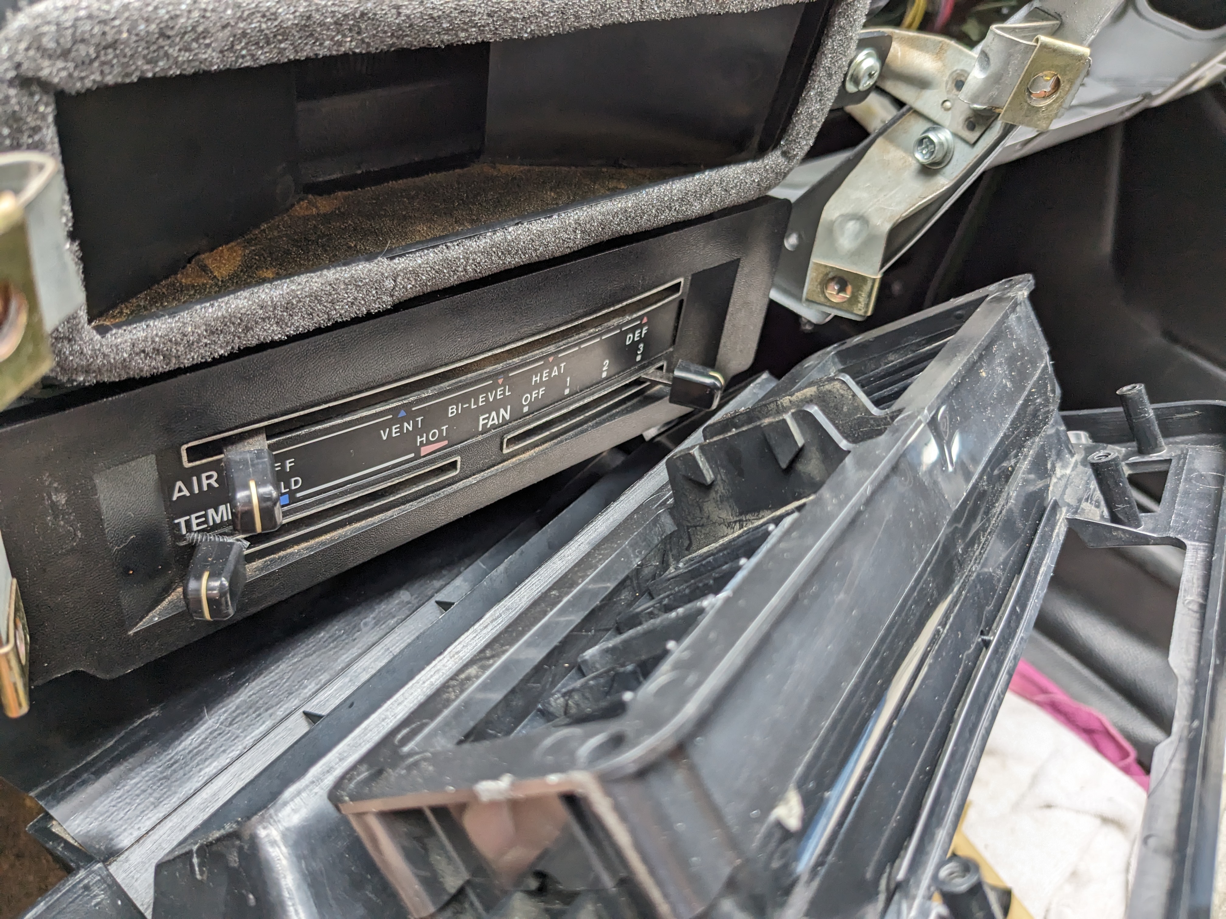
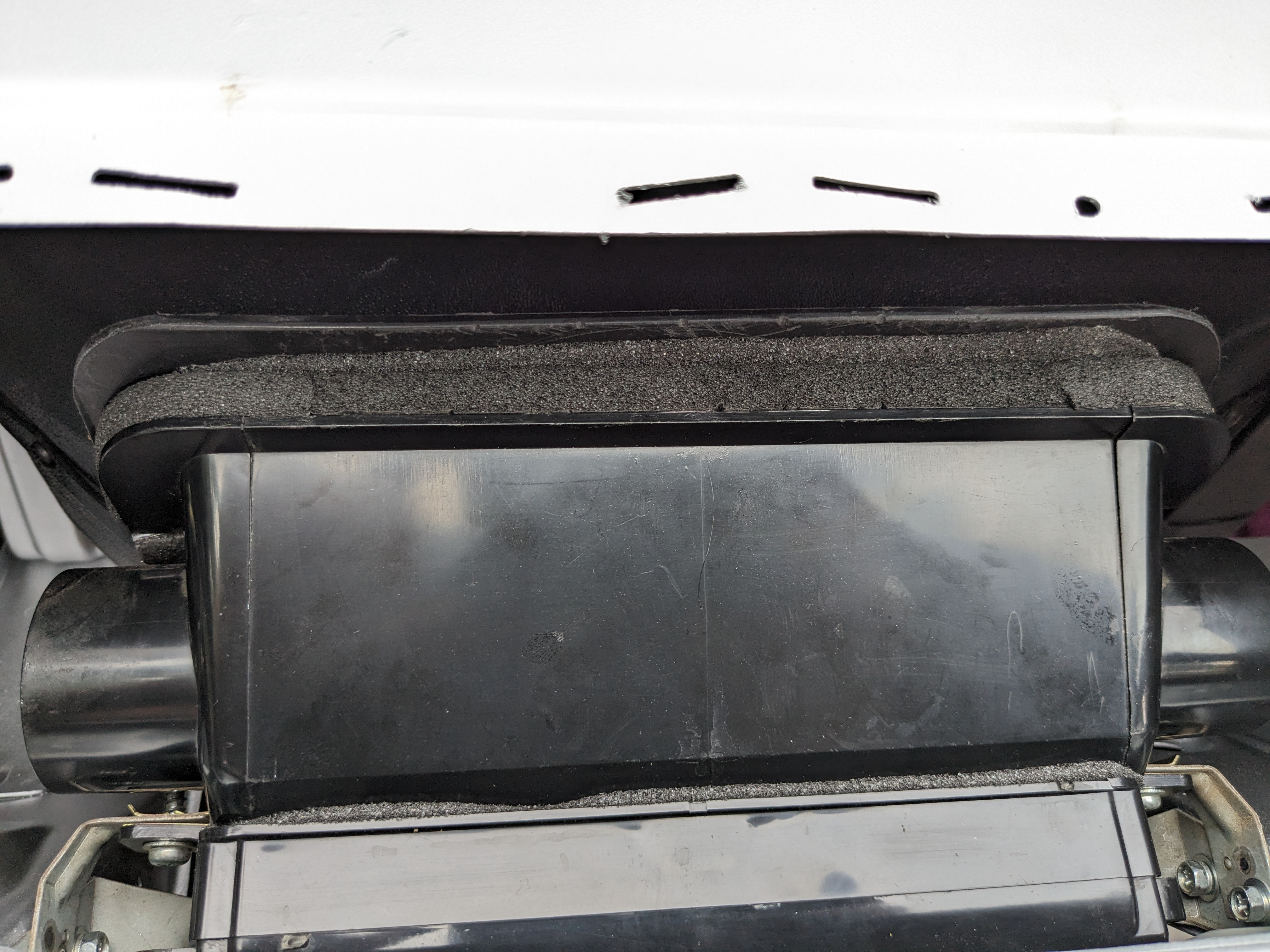
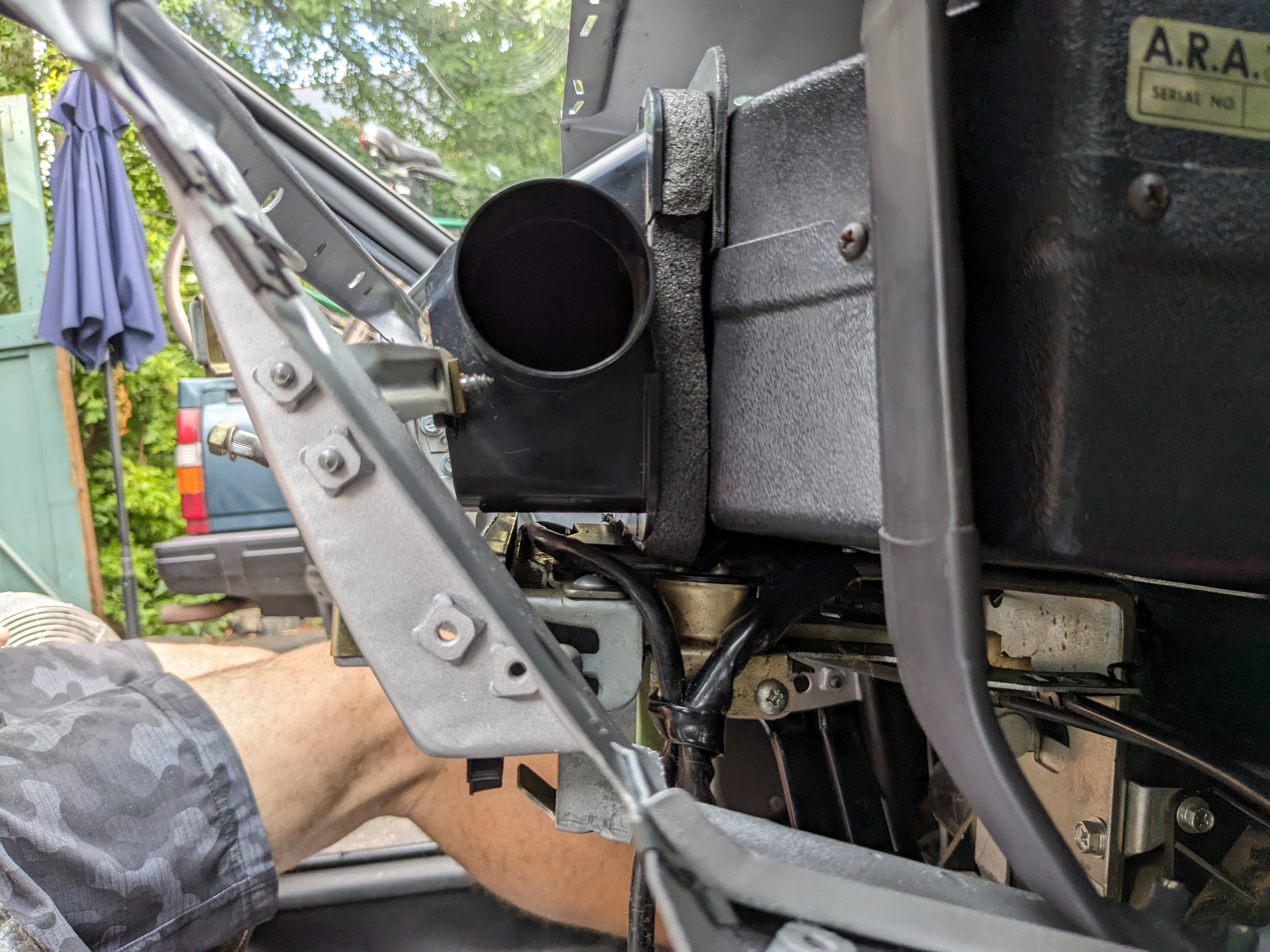
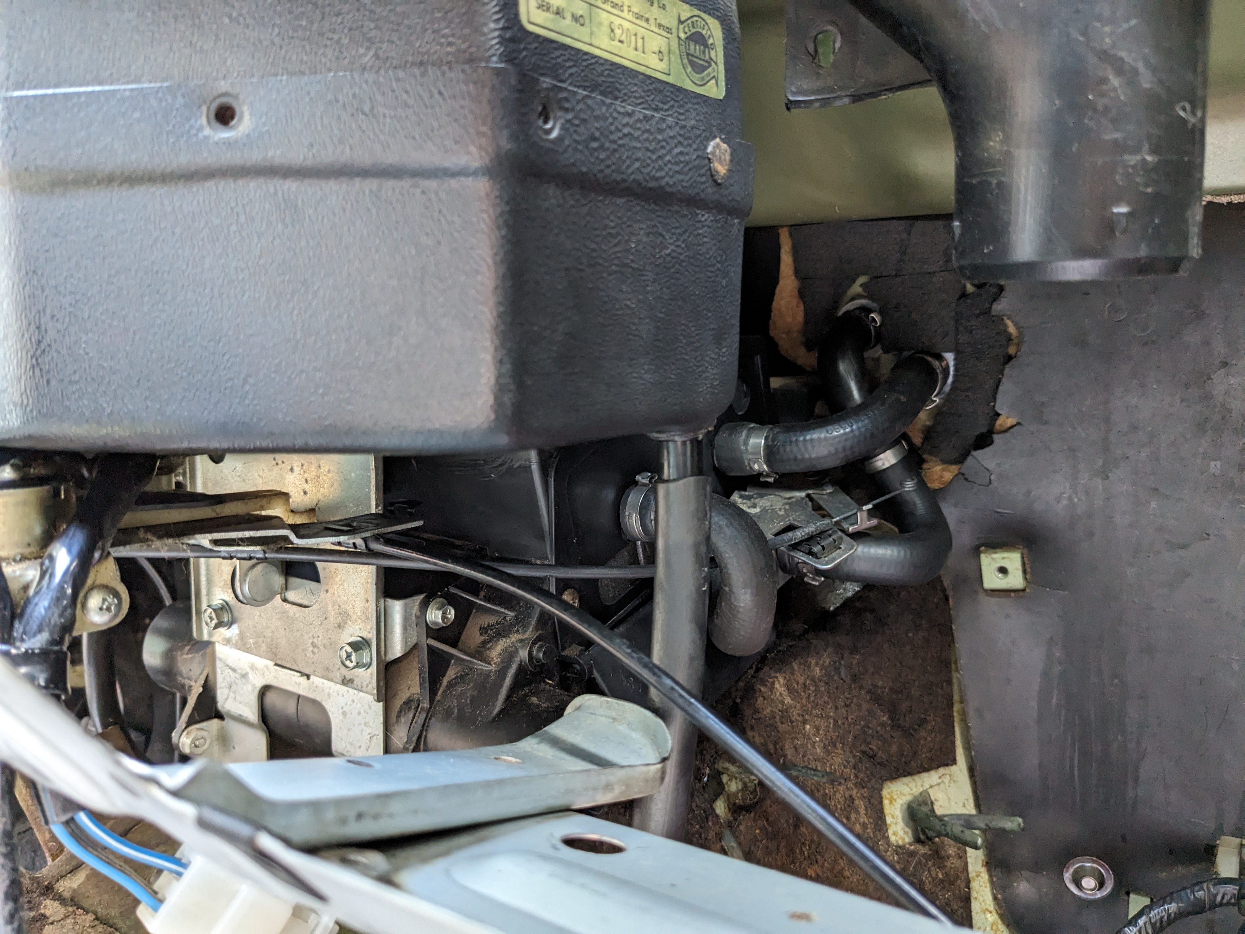
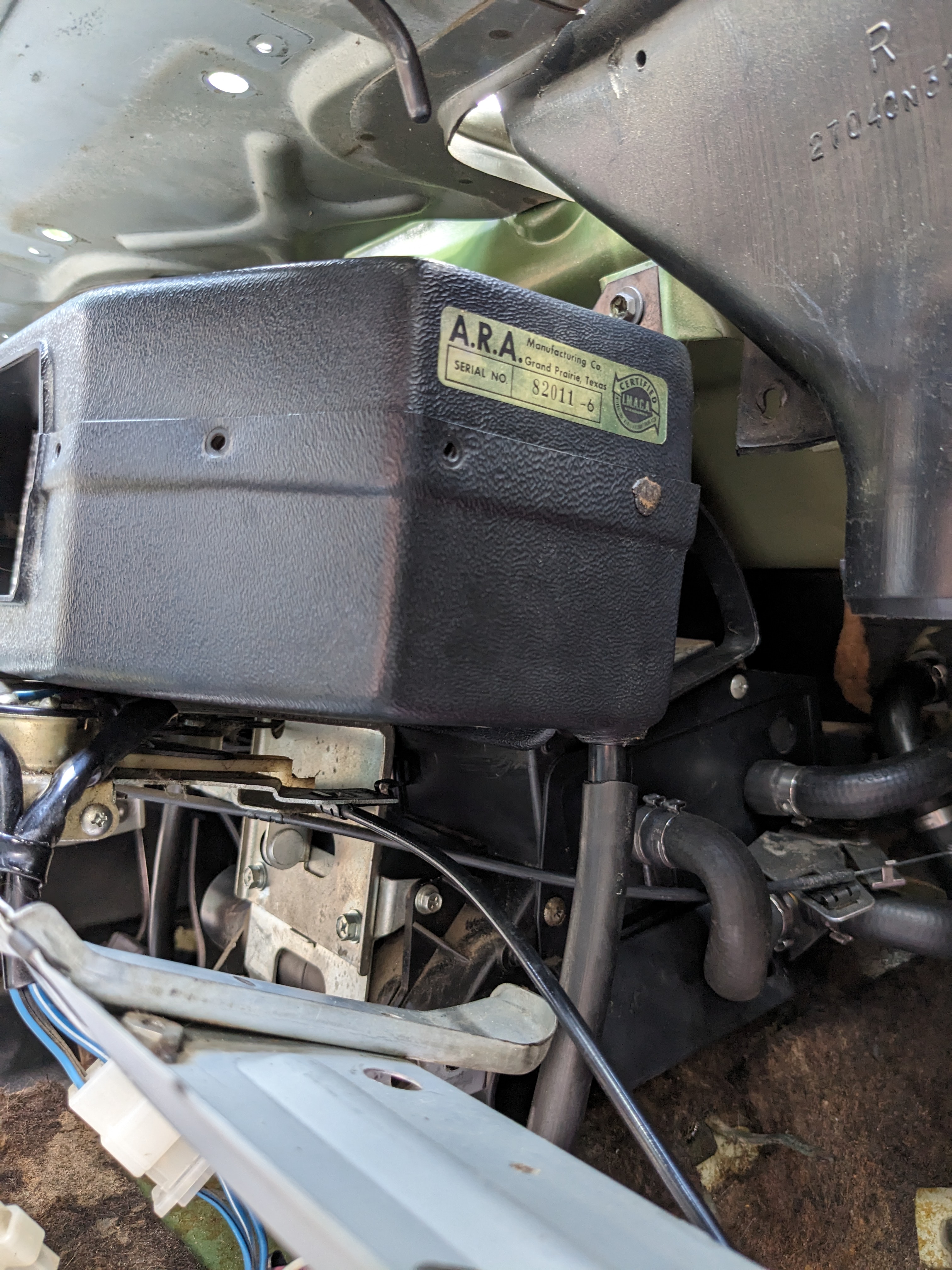
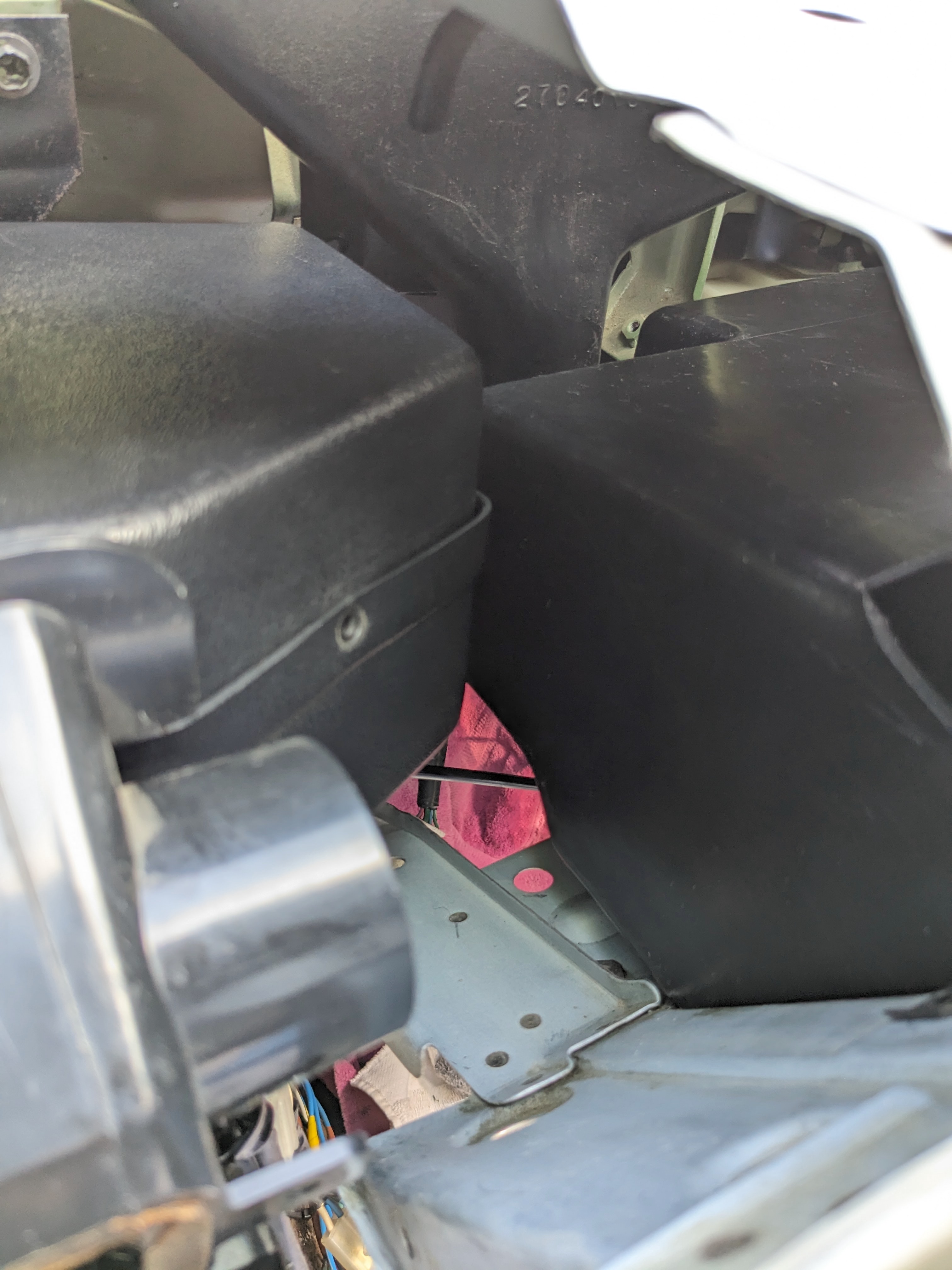
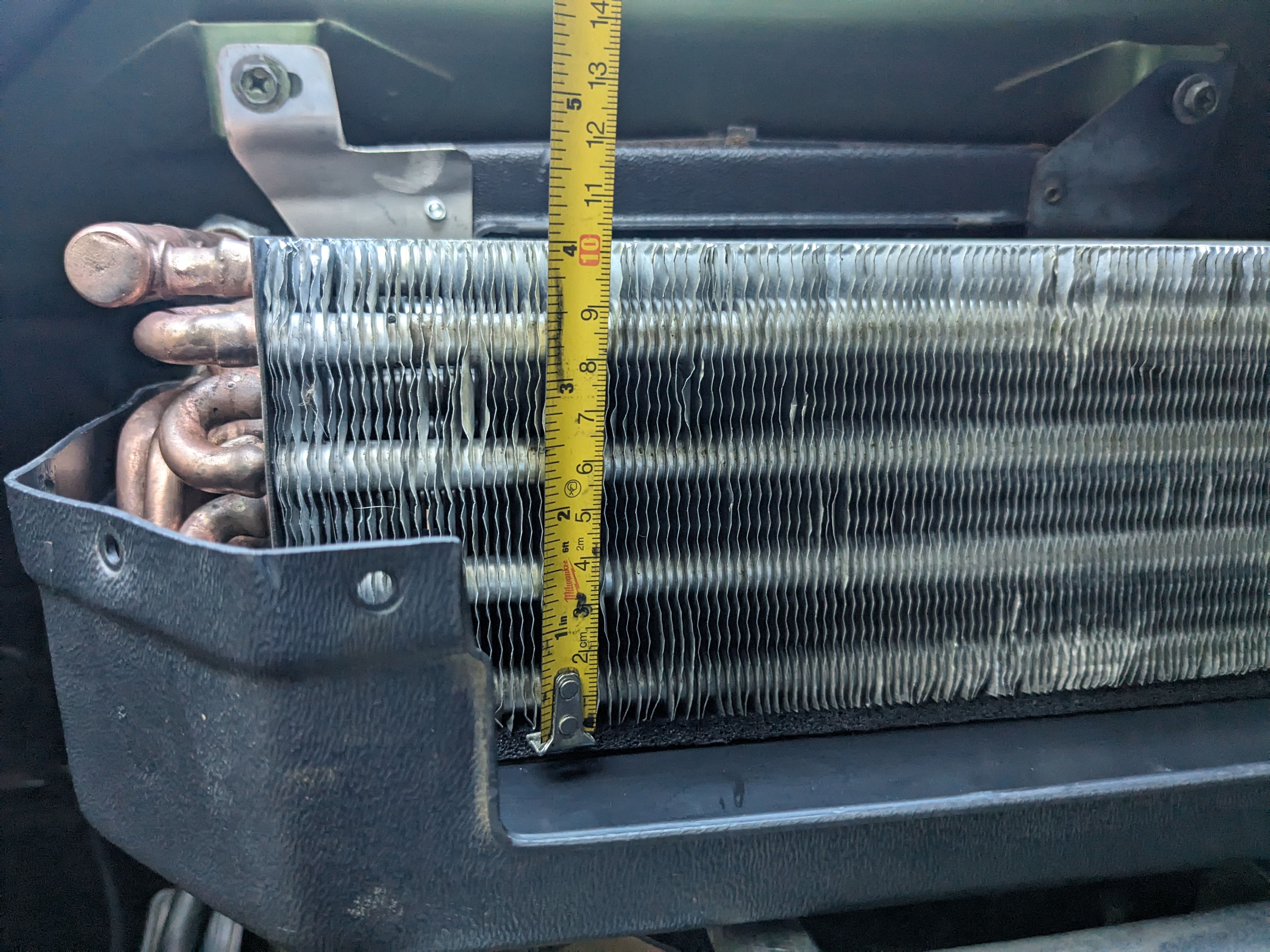
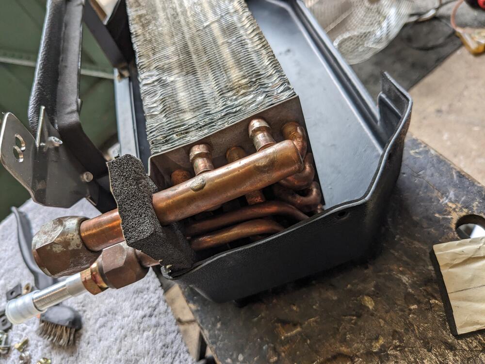
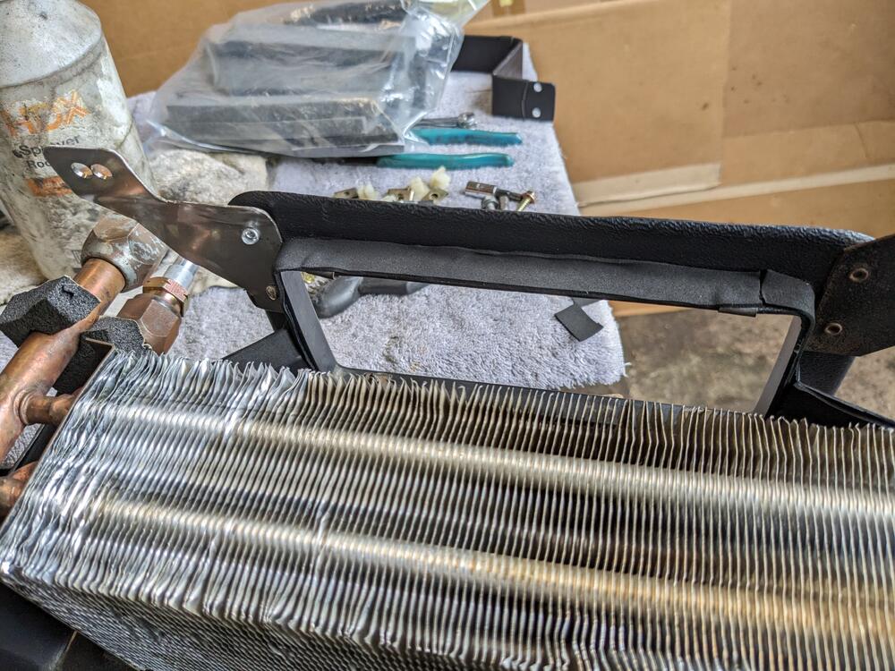
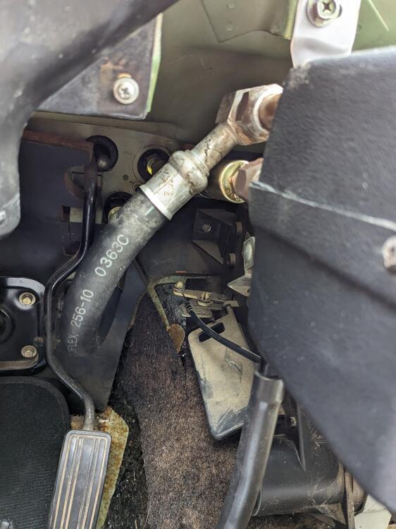
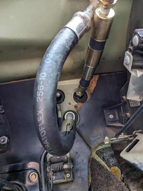
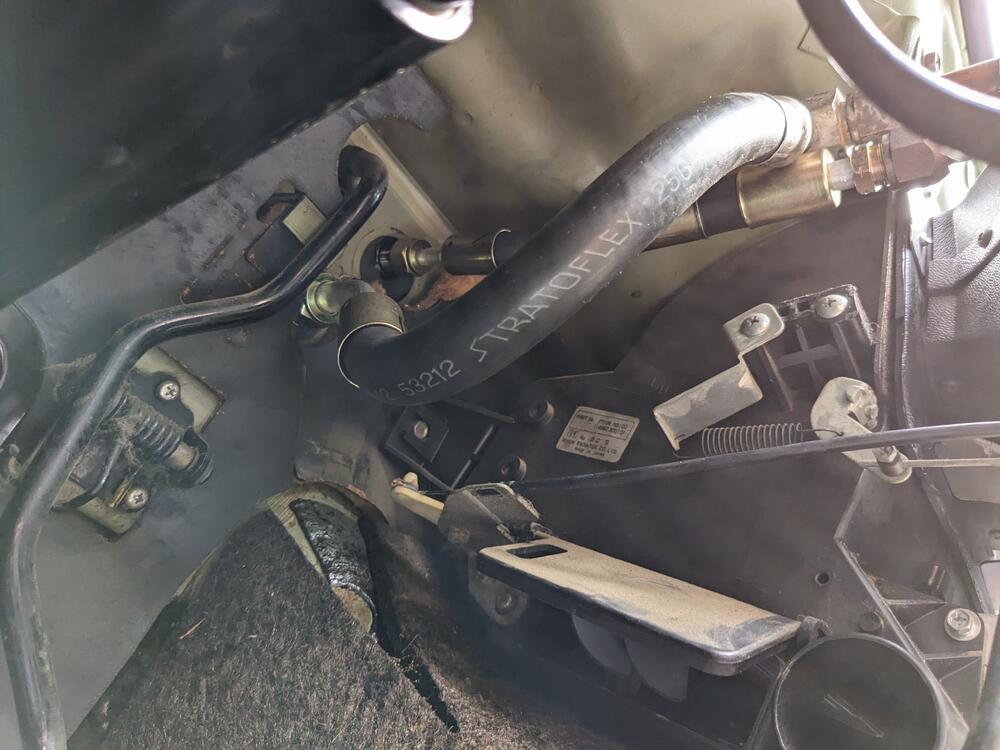
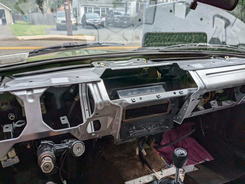
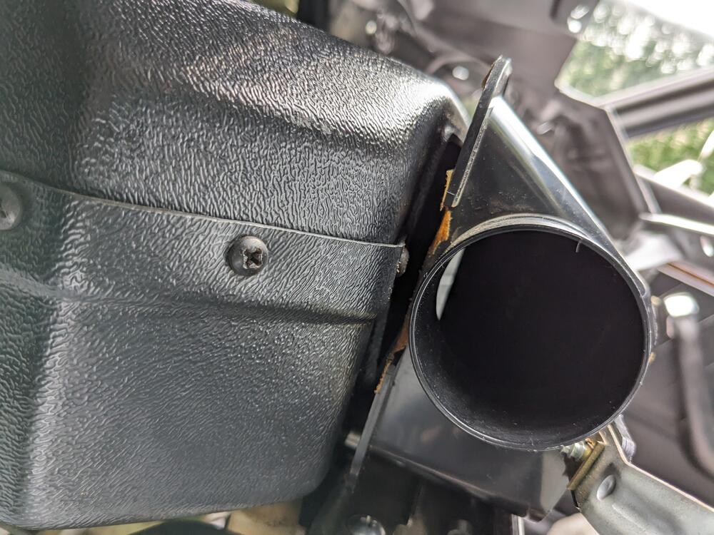
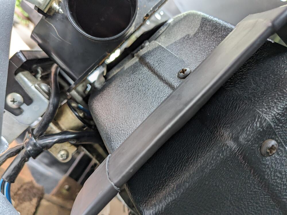
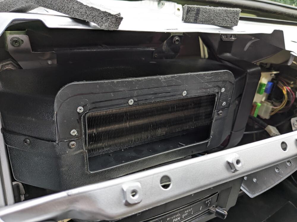
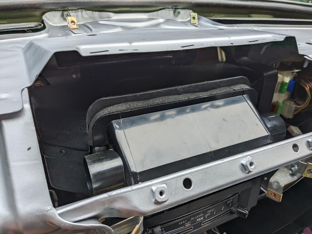
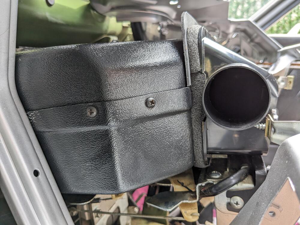
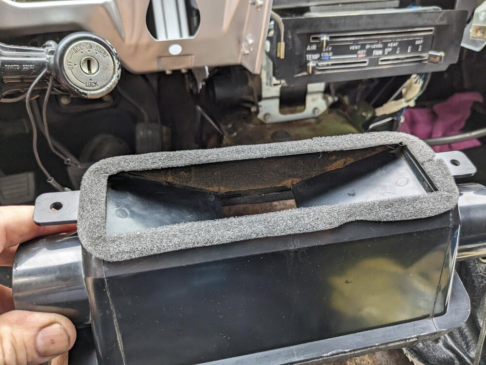
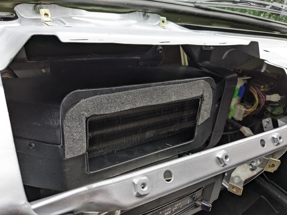
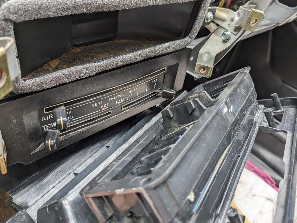
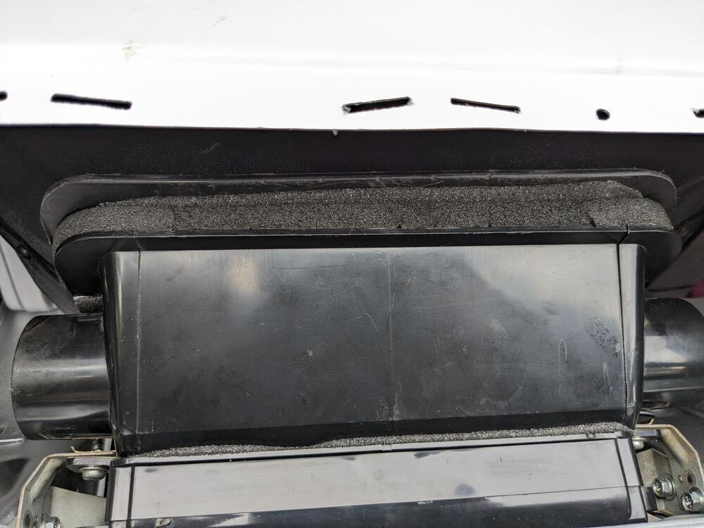
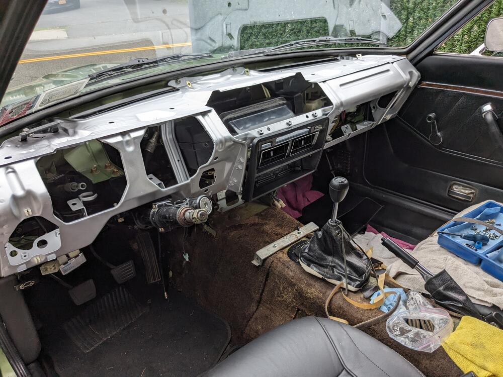
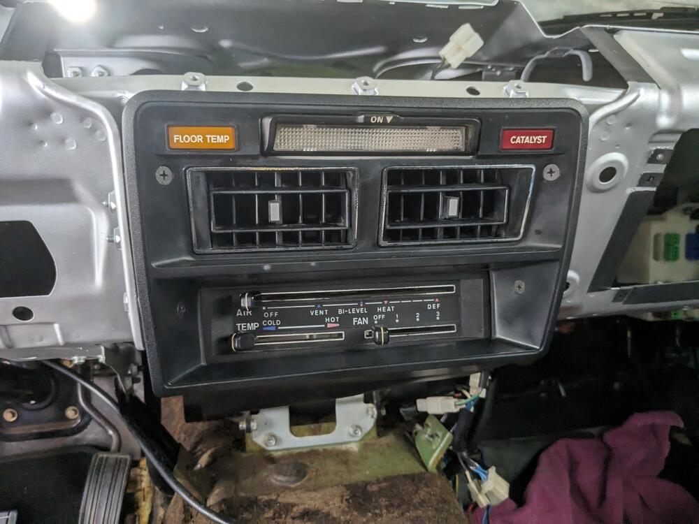
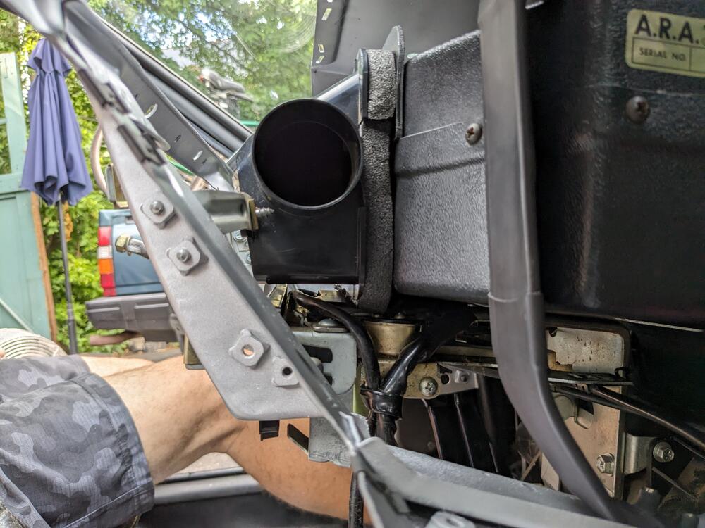
Worked on the AC lines from evaporator to firewall, sealing the box, and sealing the ductwork to the box. Fitted the dash frame to check all fitments have to crimp the fittings sealing foam for lines exiting the box closed cell foam to seal box to frame attachment test fitted evaporator box & dash frame gap around duct housing Even worse on the right added a flange to mate with the Nissan duct, so I could seal the gap. Factory evaporator box must be taller & narrower. extra thin foam on top half, due to angle of evaporator box Added thick foam to the duct, to seal against the flange then added thin foam to seal the facia vent to the duct sealed now
-
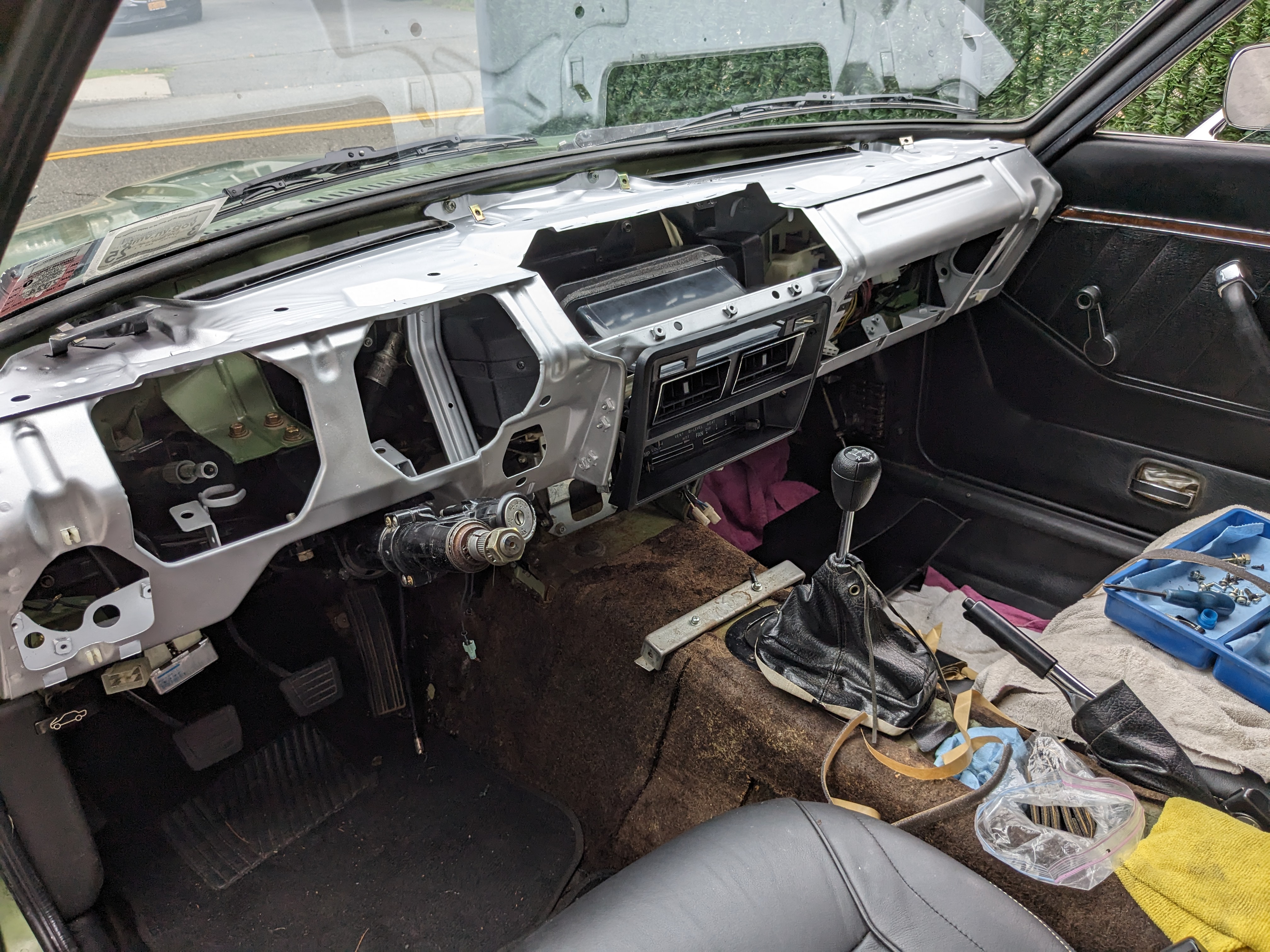
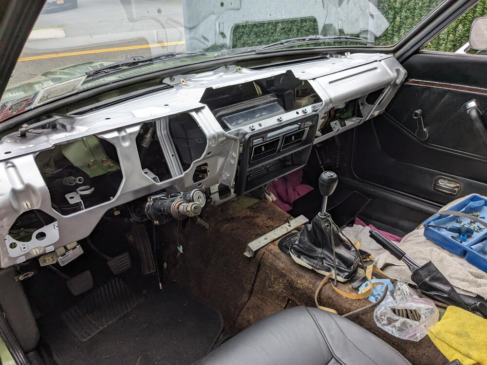
More work on the dash frame - primed & painted after fitting the right side brace. Test fitting with Evaporator box, duct & control facia
-
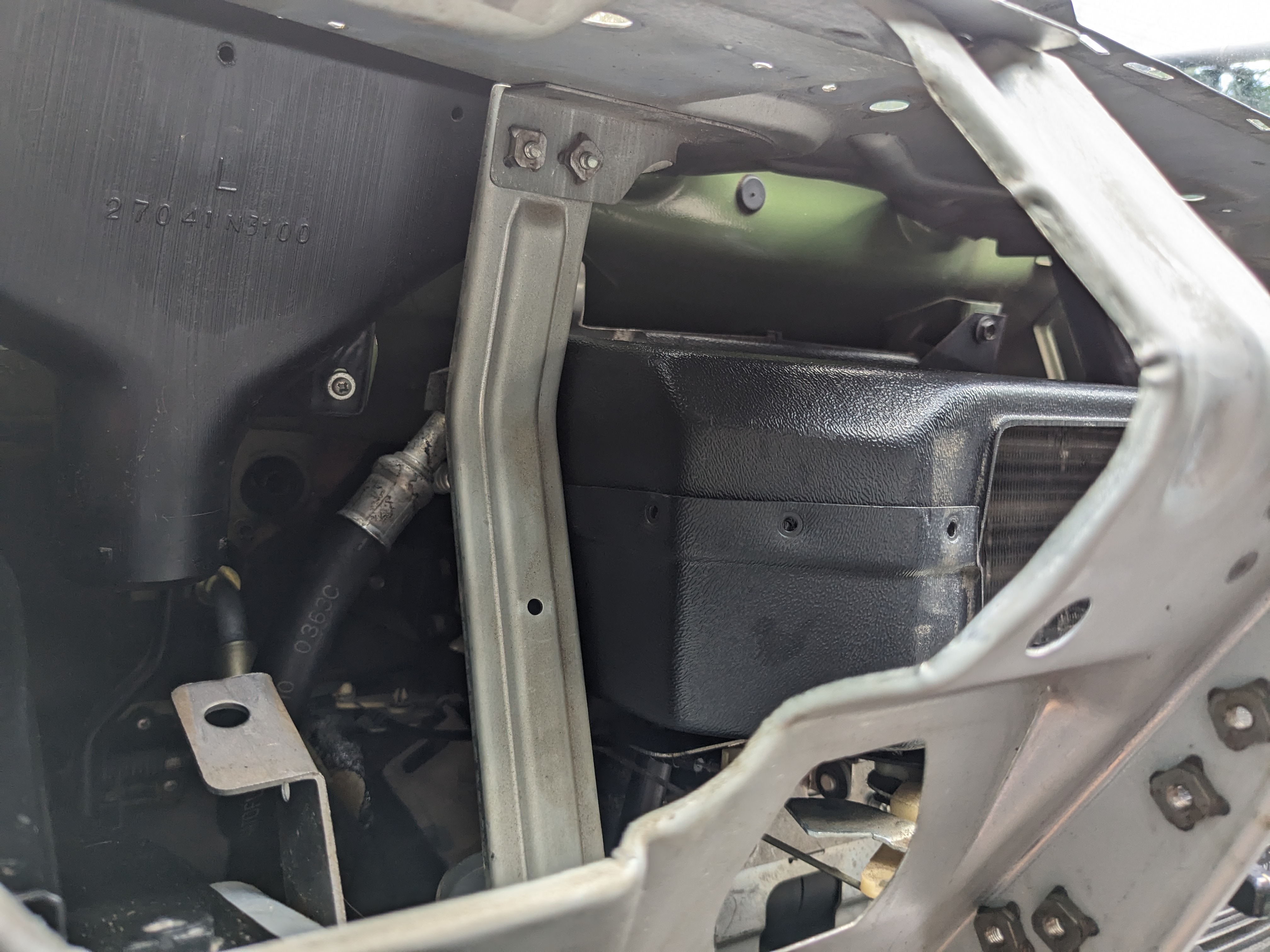
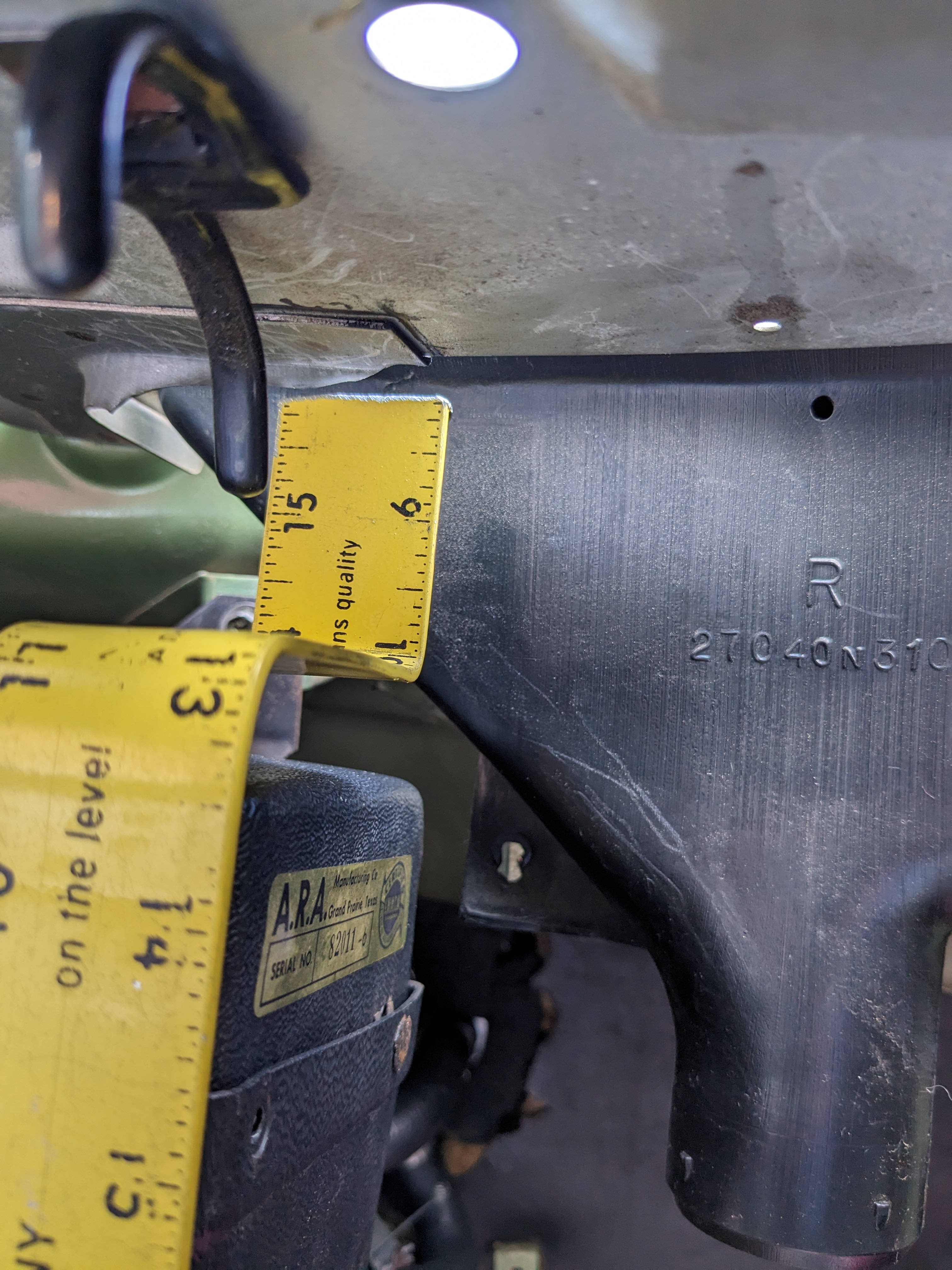
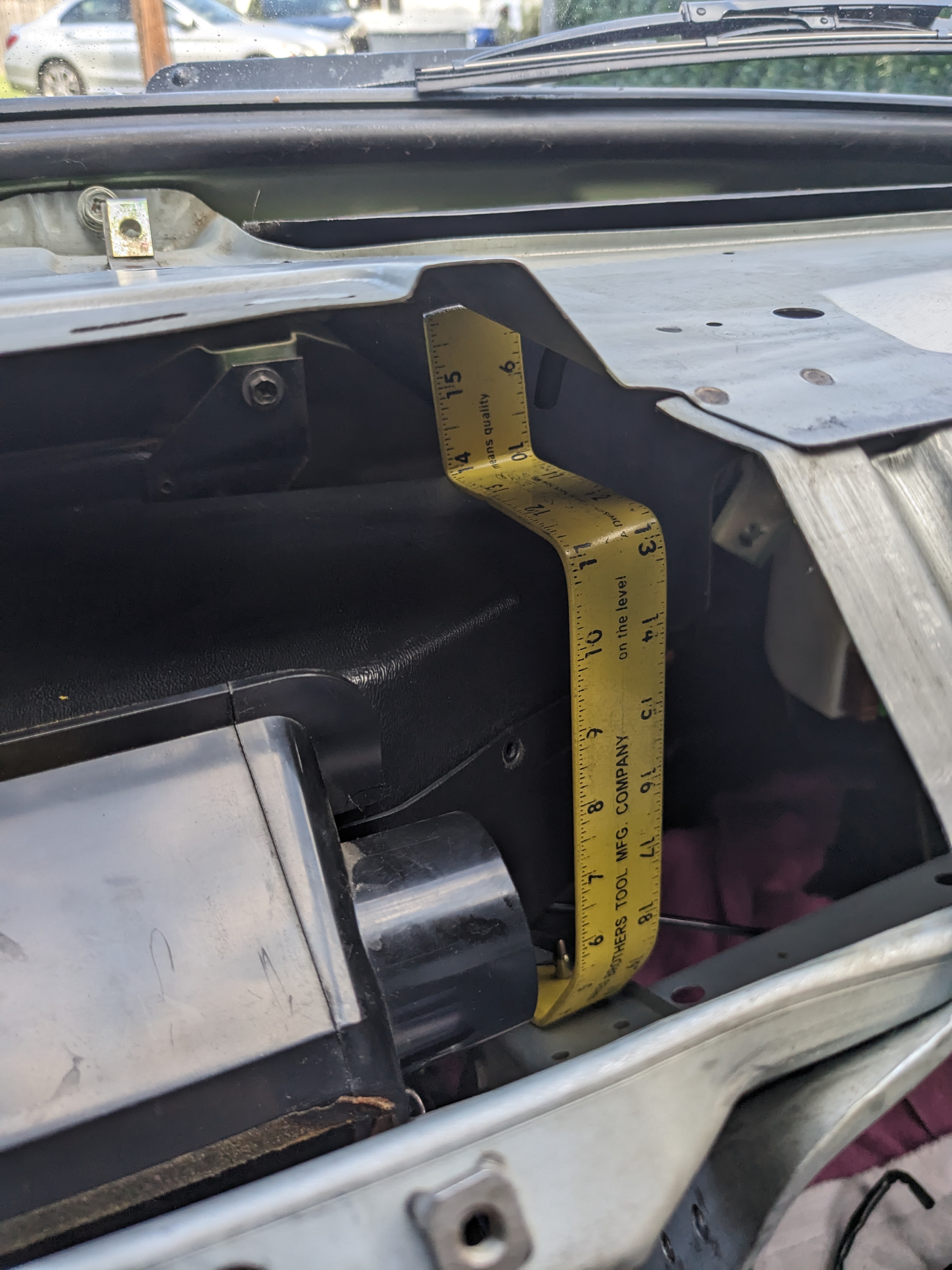
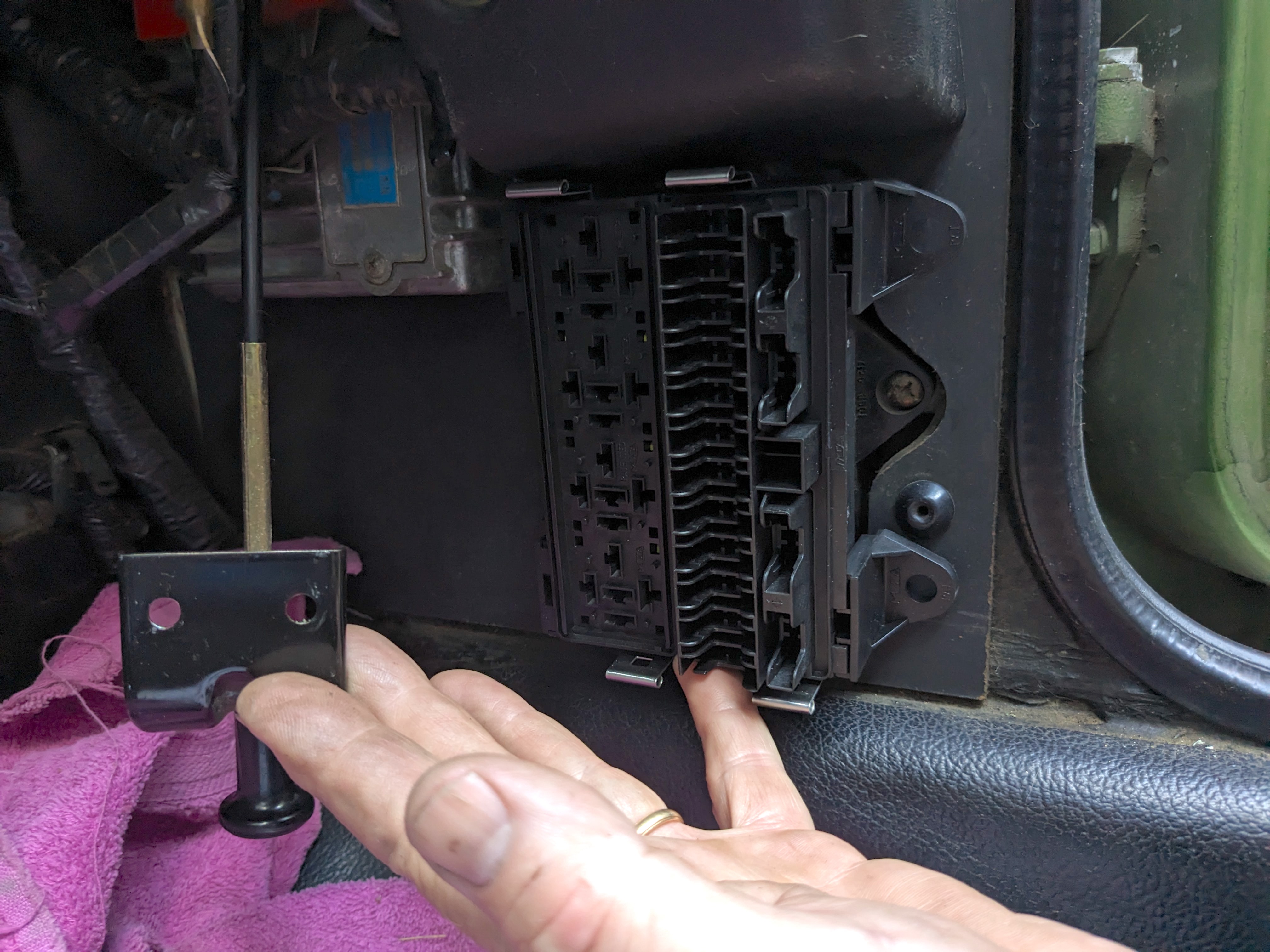
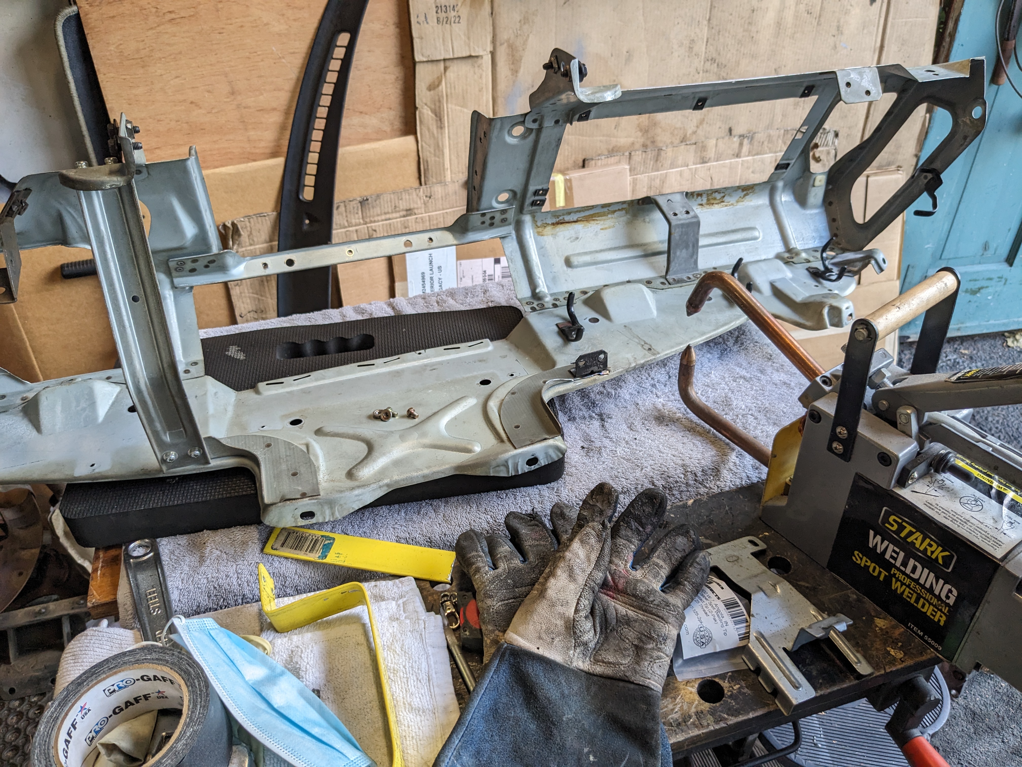
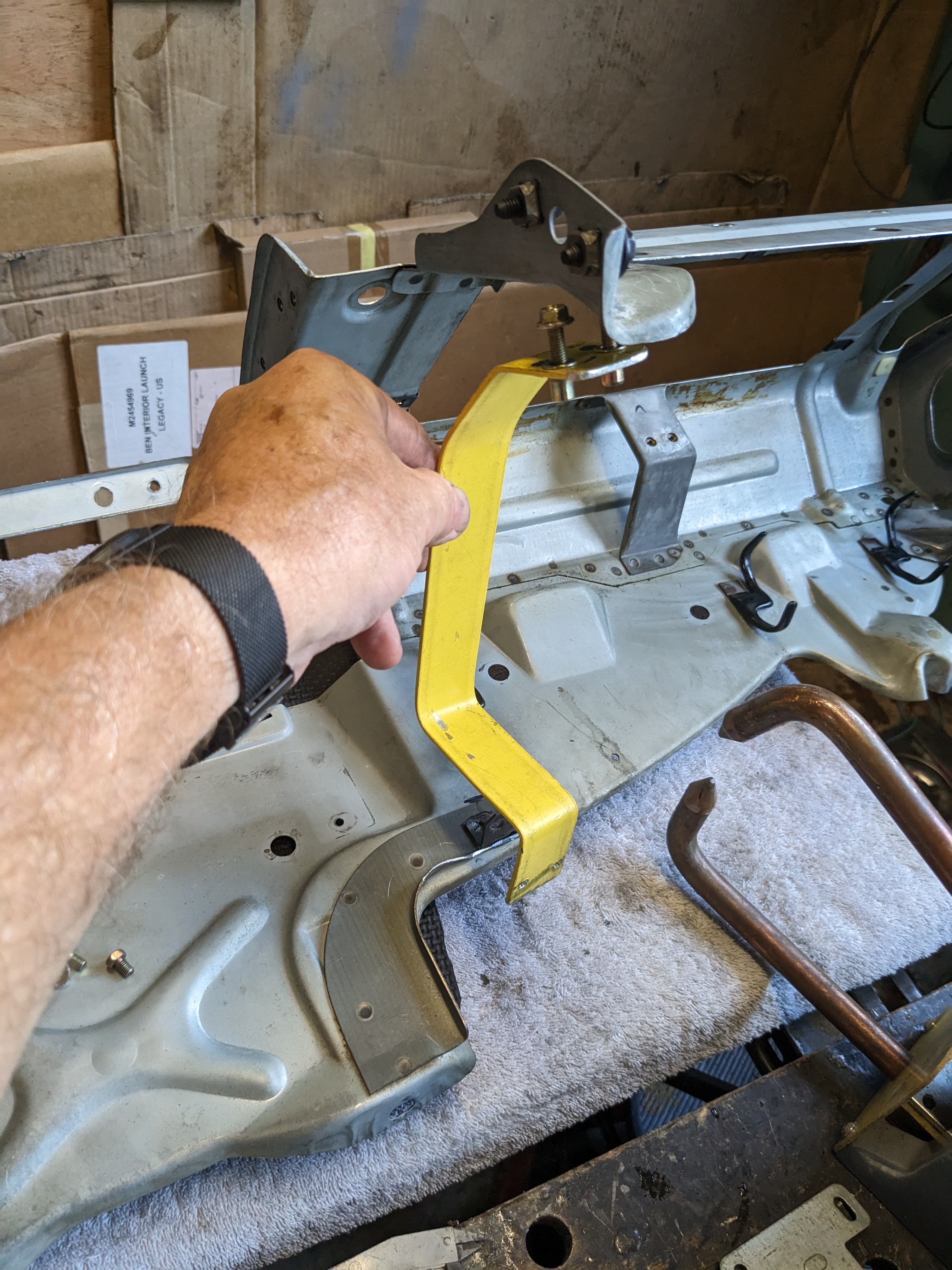
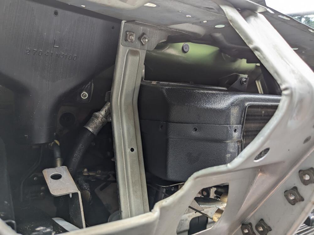
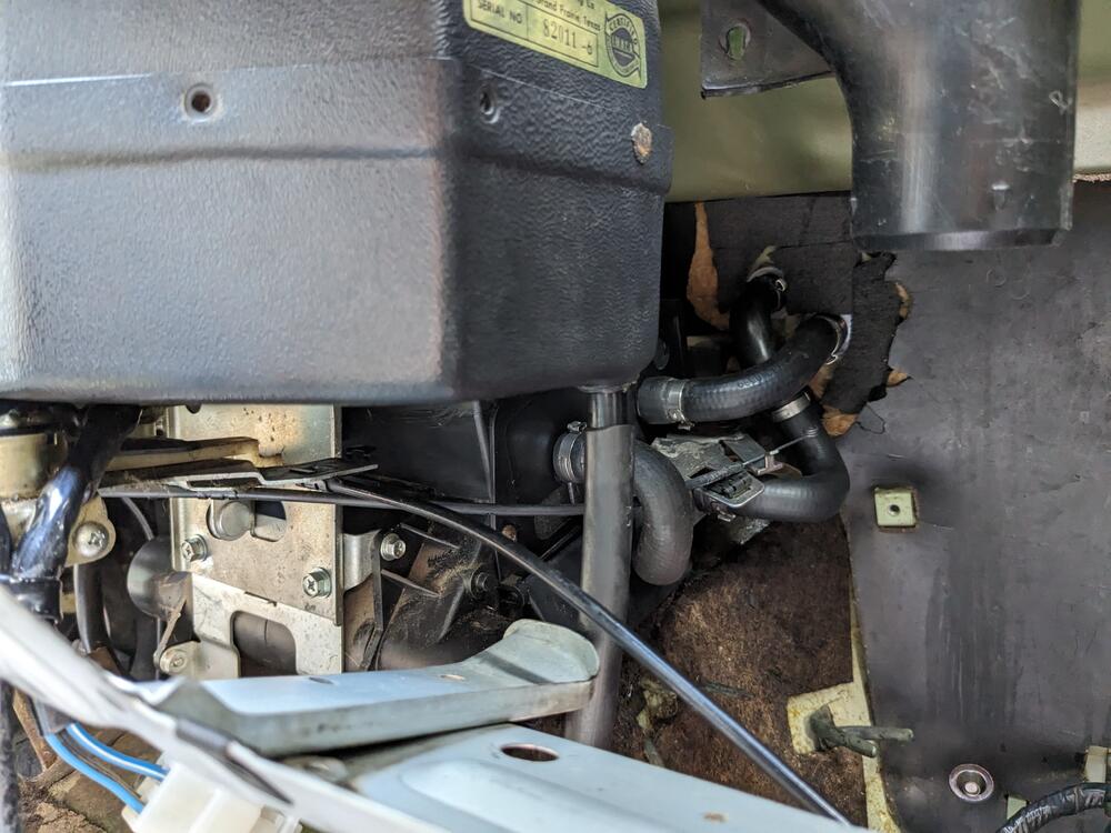
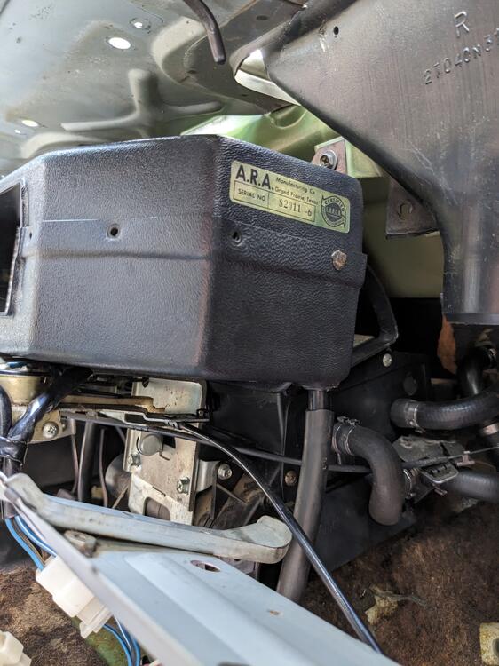
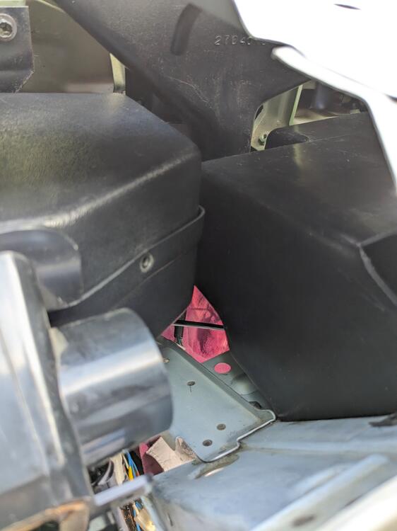
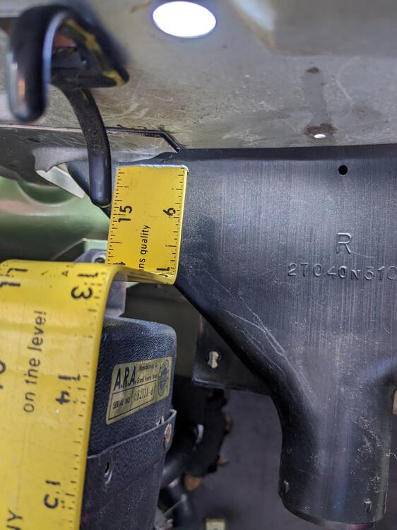
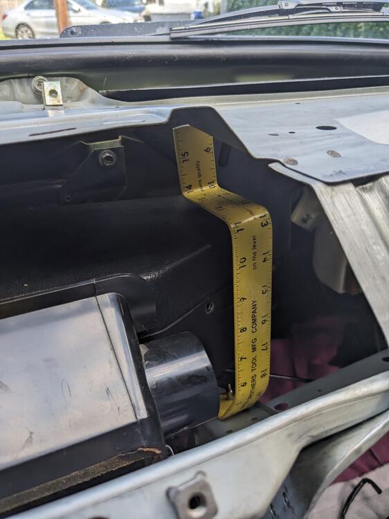
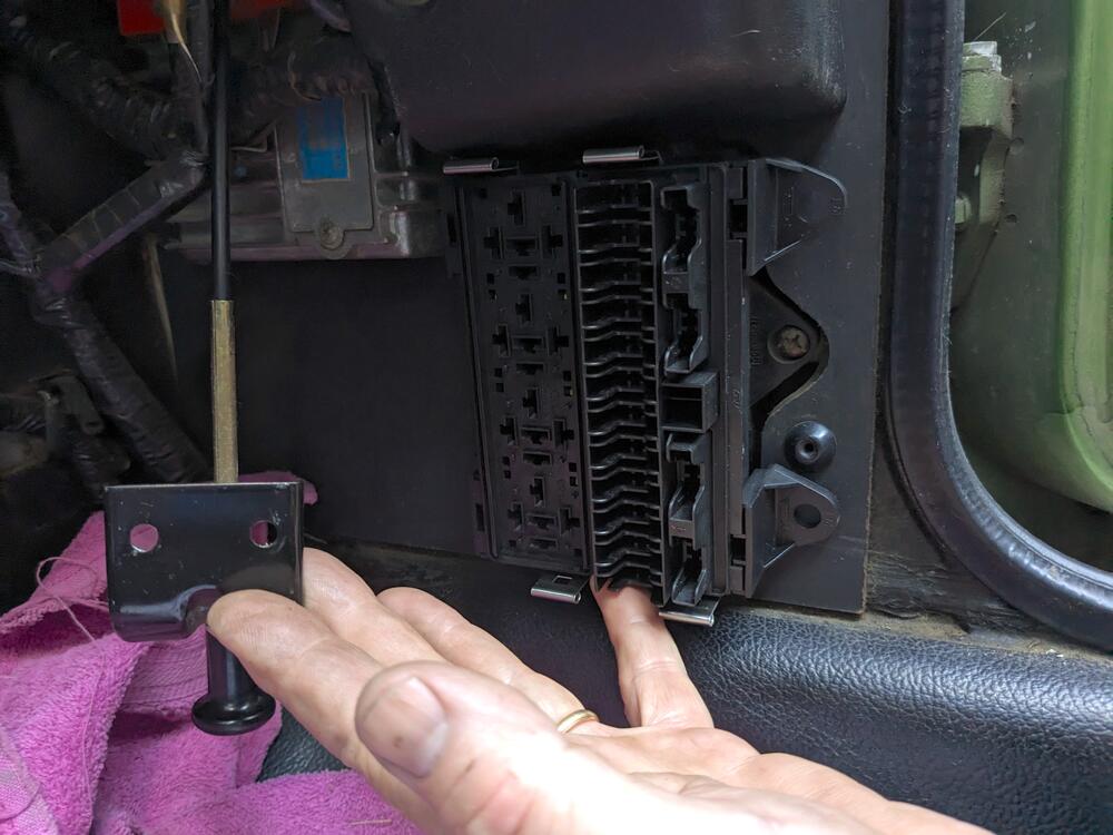
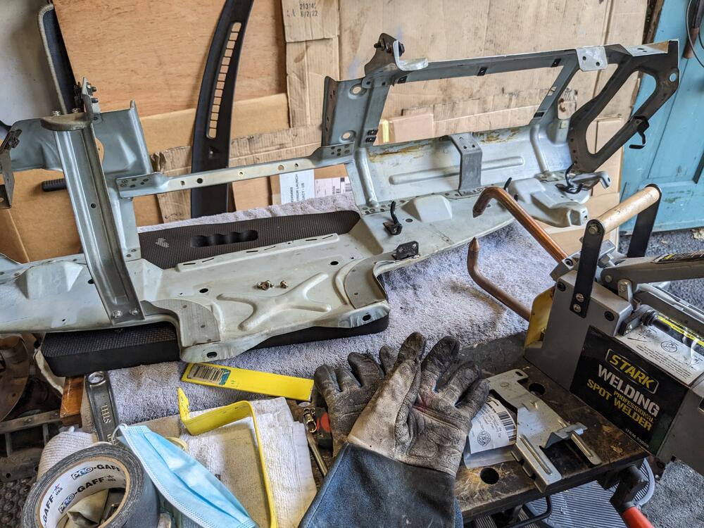
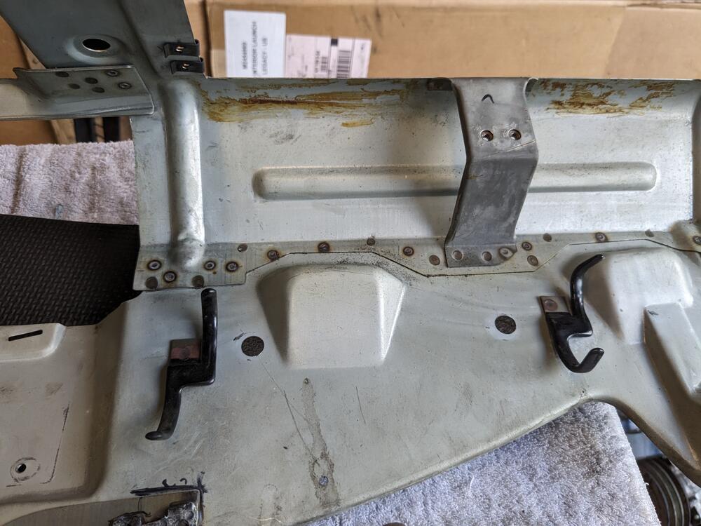
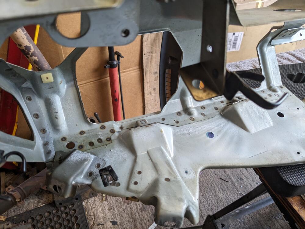
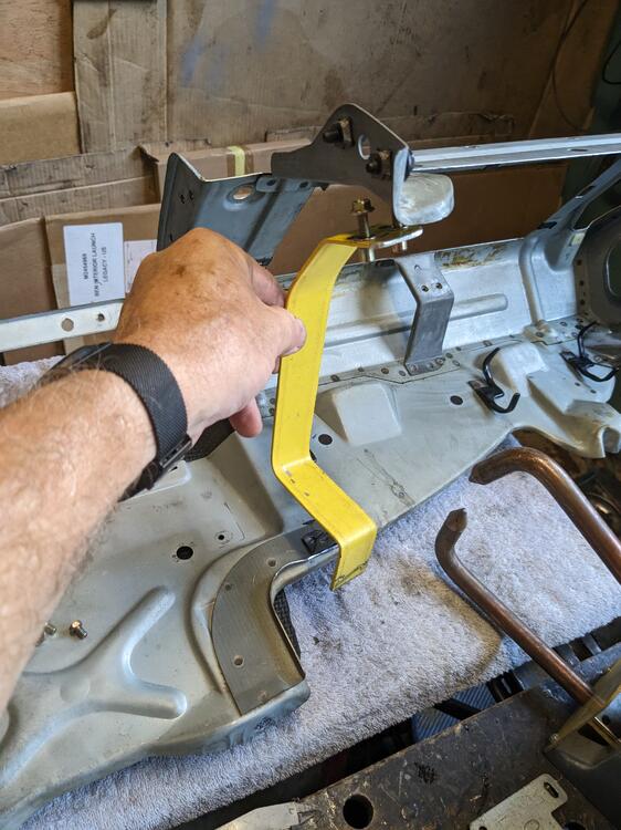
Had a little time to work on the dash today, so I put the frame in the car to figure out the right side support brace Left side brace sits right up against the box Right side - definitely was removed due to Evaporator set the glovebox in place, to check clearance outside the evaporator box - none Used a aluminum ruler to make a brace I'll add an angle bracket back to the dash frame, to attach the brace to frame back out to finish up the angle bracket for the brace & add spot welds to the existing structure Going to replace the fusebox with an MTA 15 ATC fusebox, and a (4) relay panel l
-
That explains why they fit so nicely then - interesting that someone put them on a Volvo 240 😄
-
Finished the compressor mount . Tacked in place
-
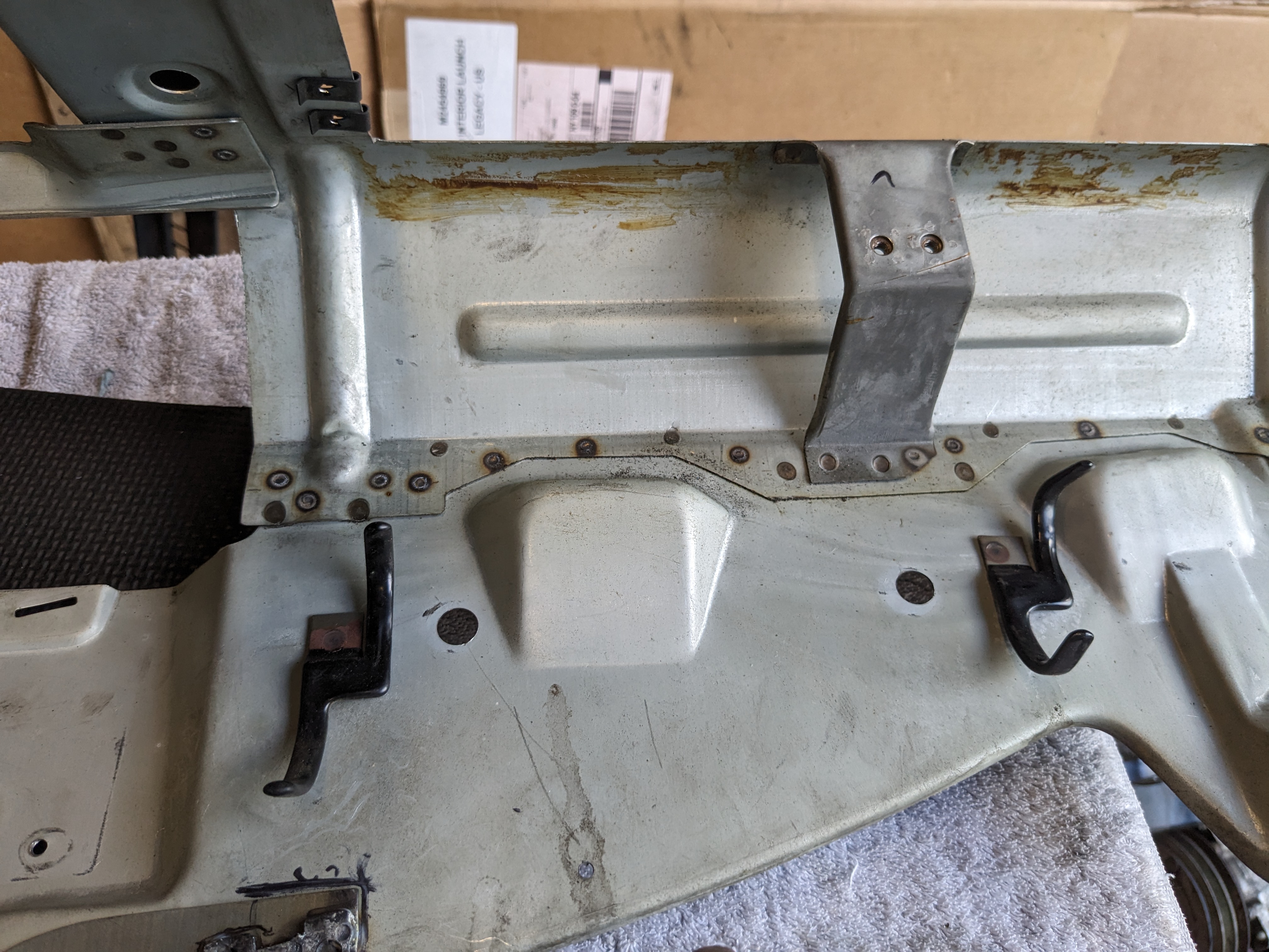
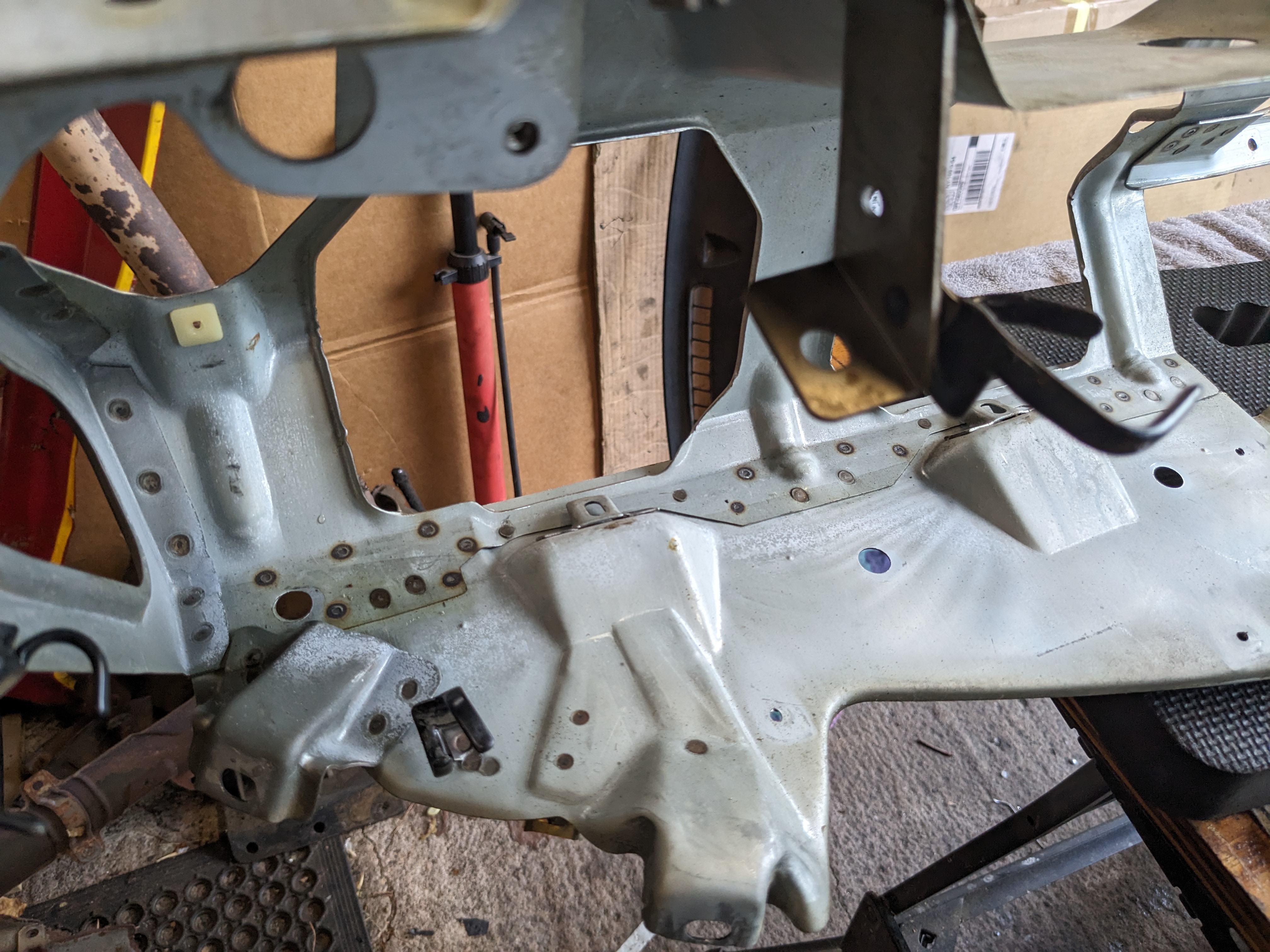
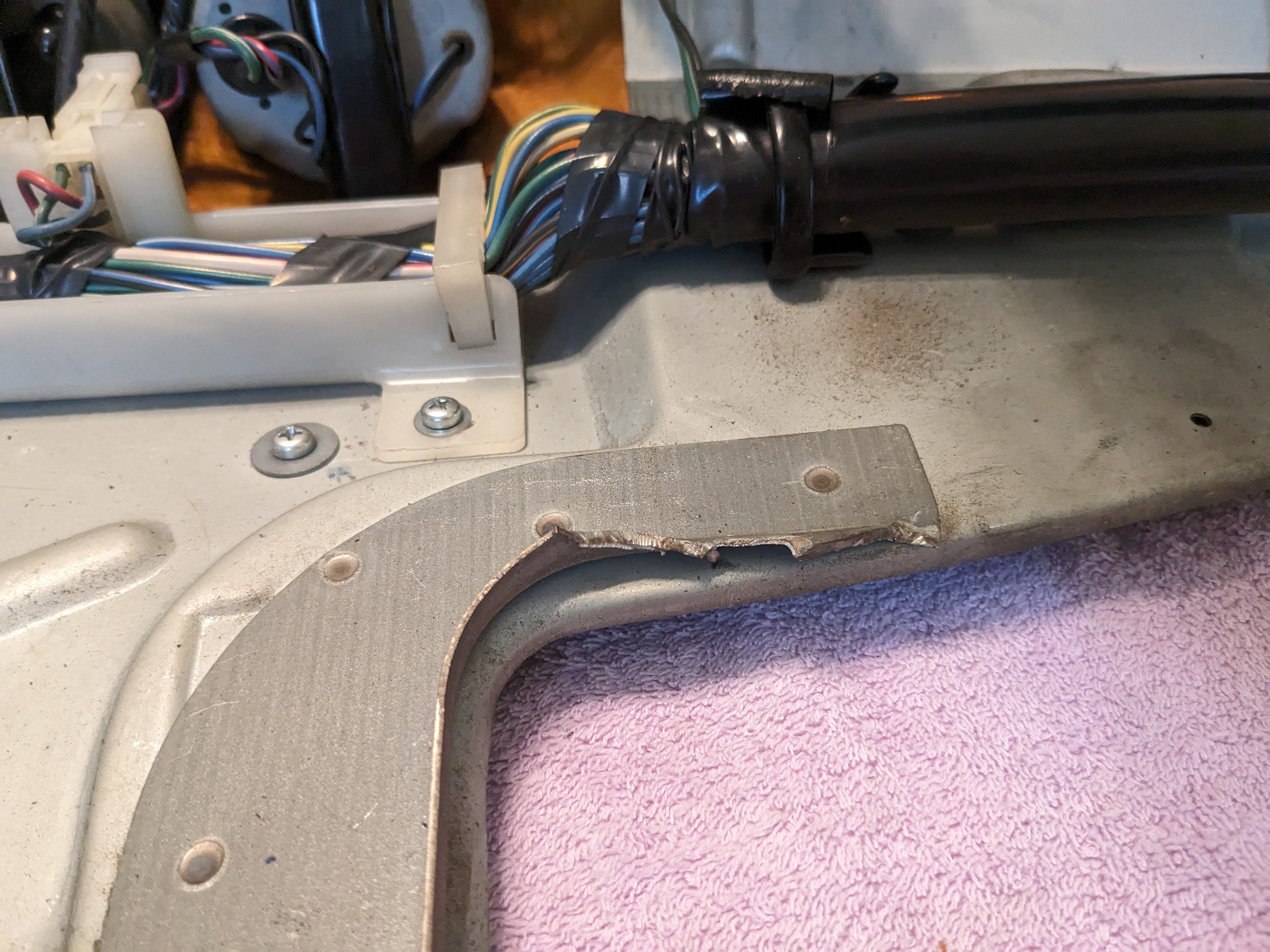
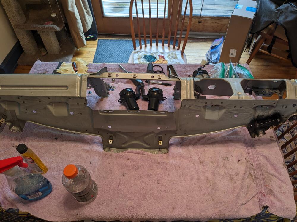
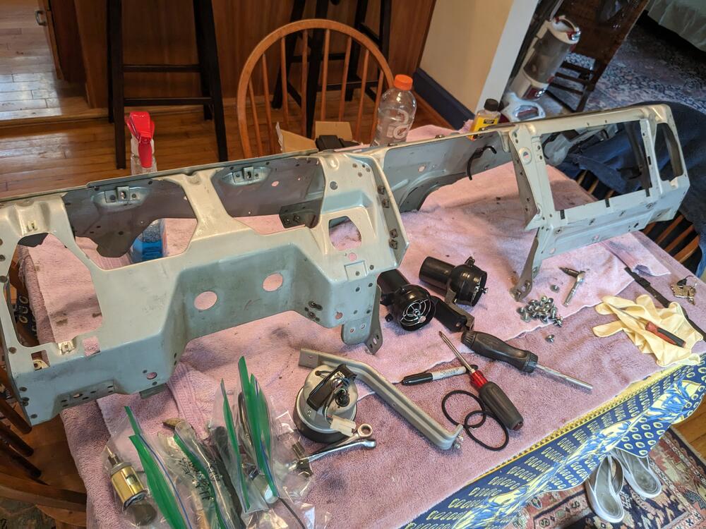
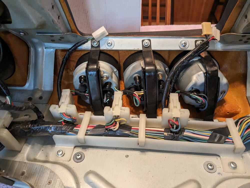
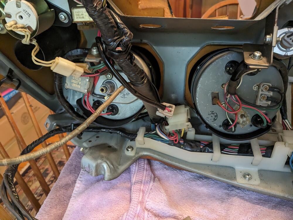
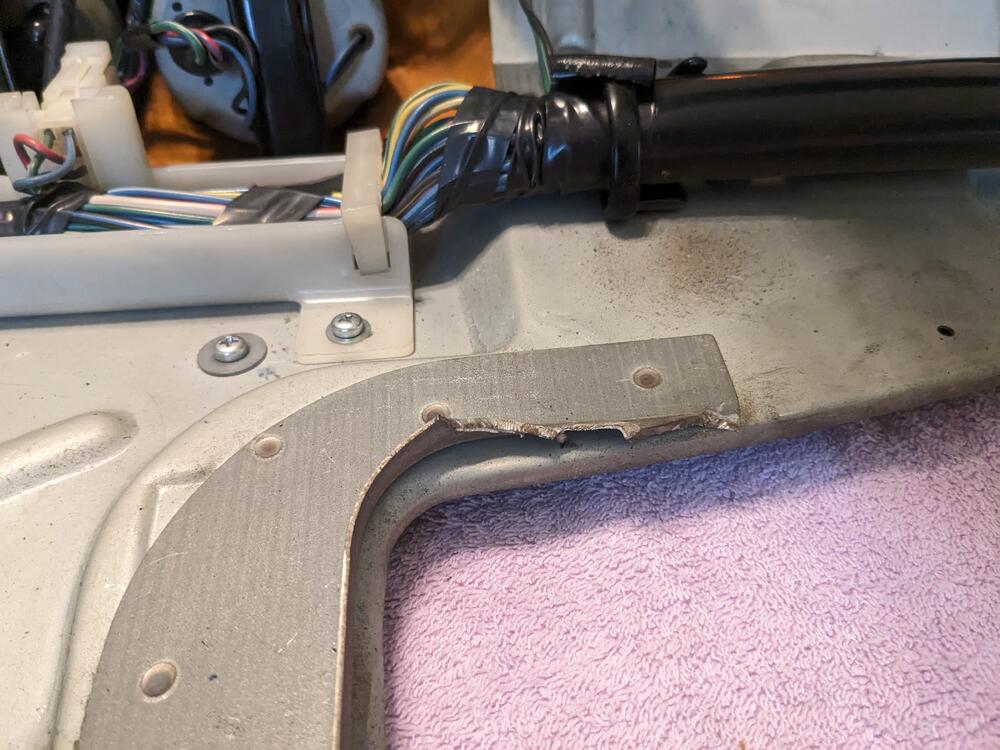
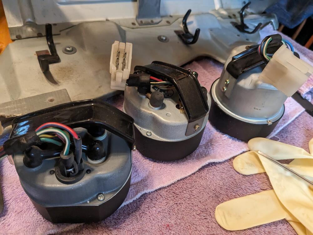
Pulled my dash during the week, today I stripped the frame The right center support was cut off - I assume due tot he aftermarket AC evaporator box. I'm going to have to figure out how to make a new one. I'll install the stripped frame over the HVAC to see how I can add one back. I'll also add some more spot welds in-between the existing welds to reinforce it. I'd like to make sure my new dash says unstressed as possible. The construction & assembly on these Datsuns is very nice. Harnesses properly secured, everything well organised, very tidy indeed!
-
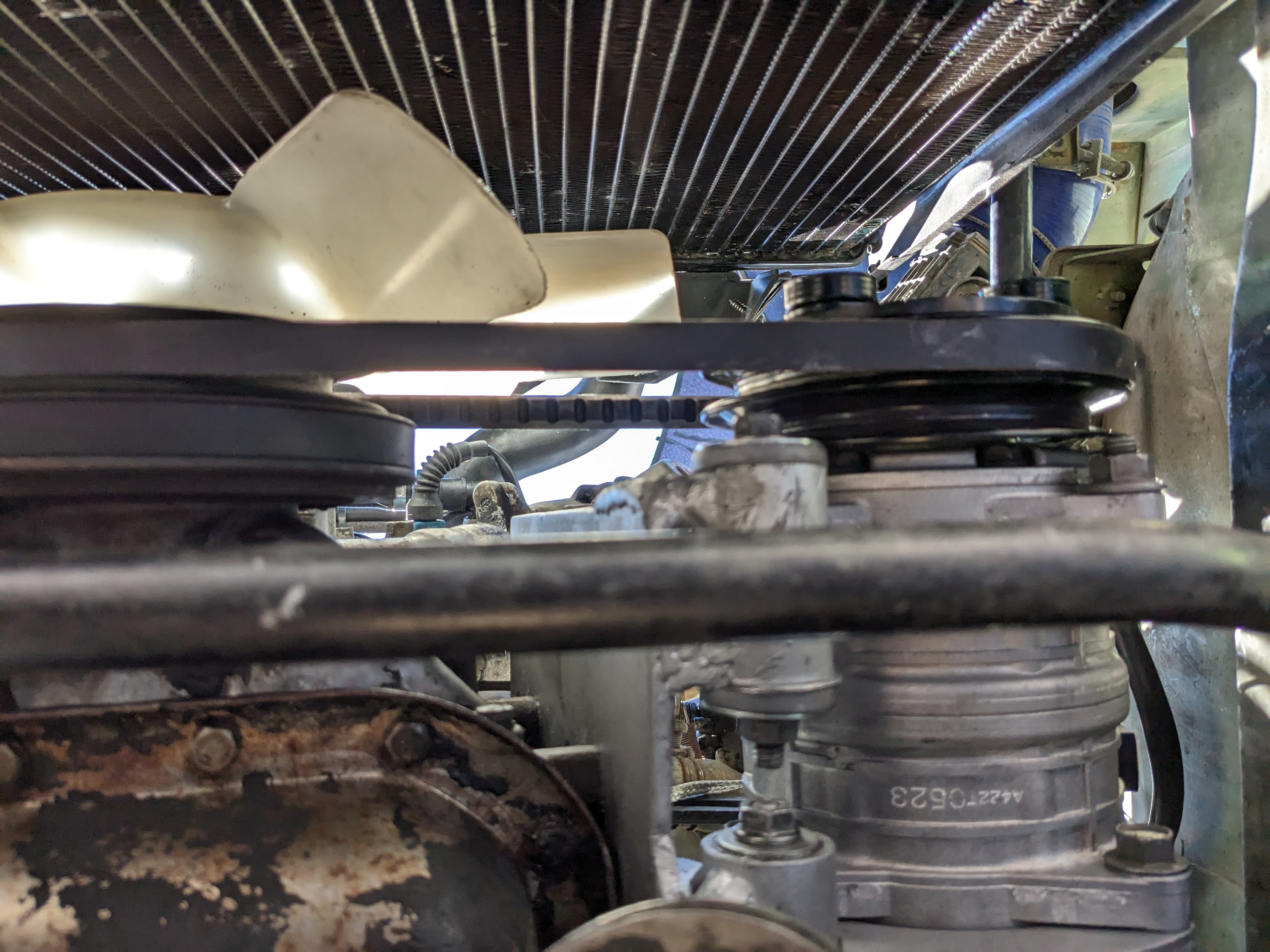
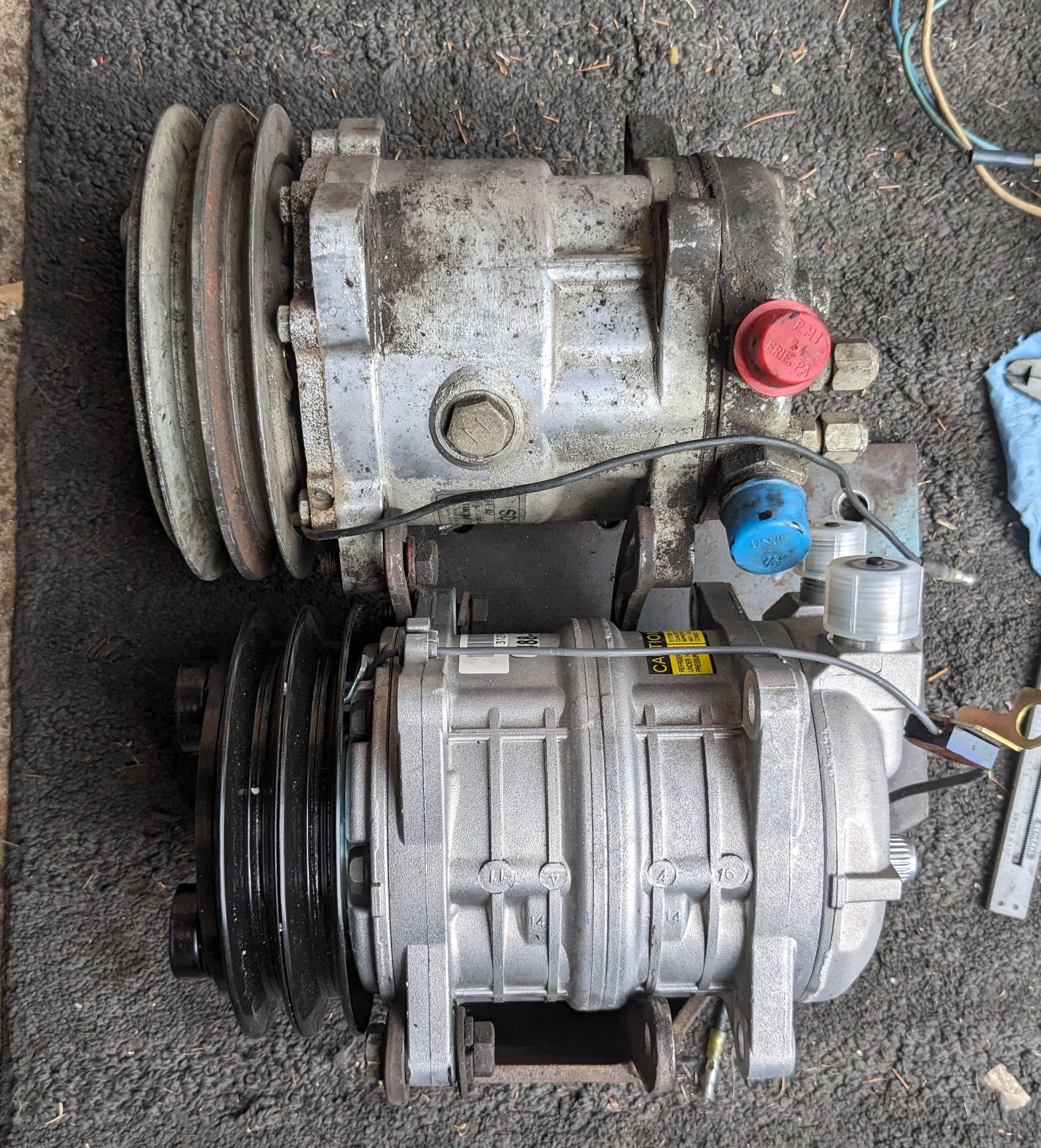
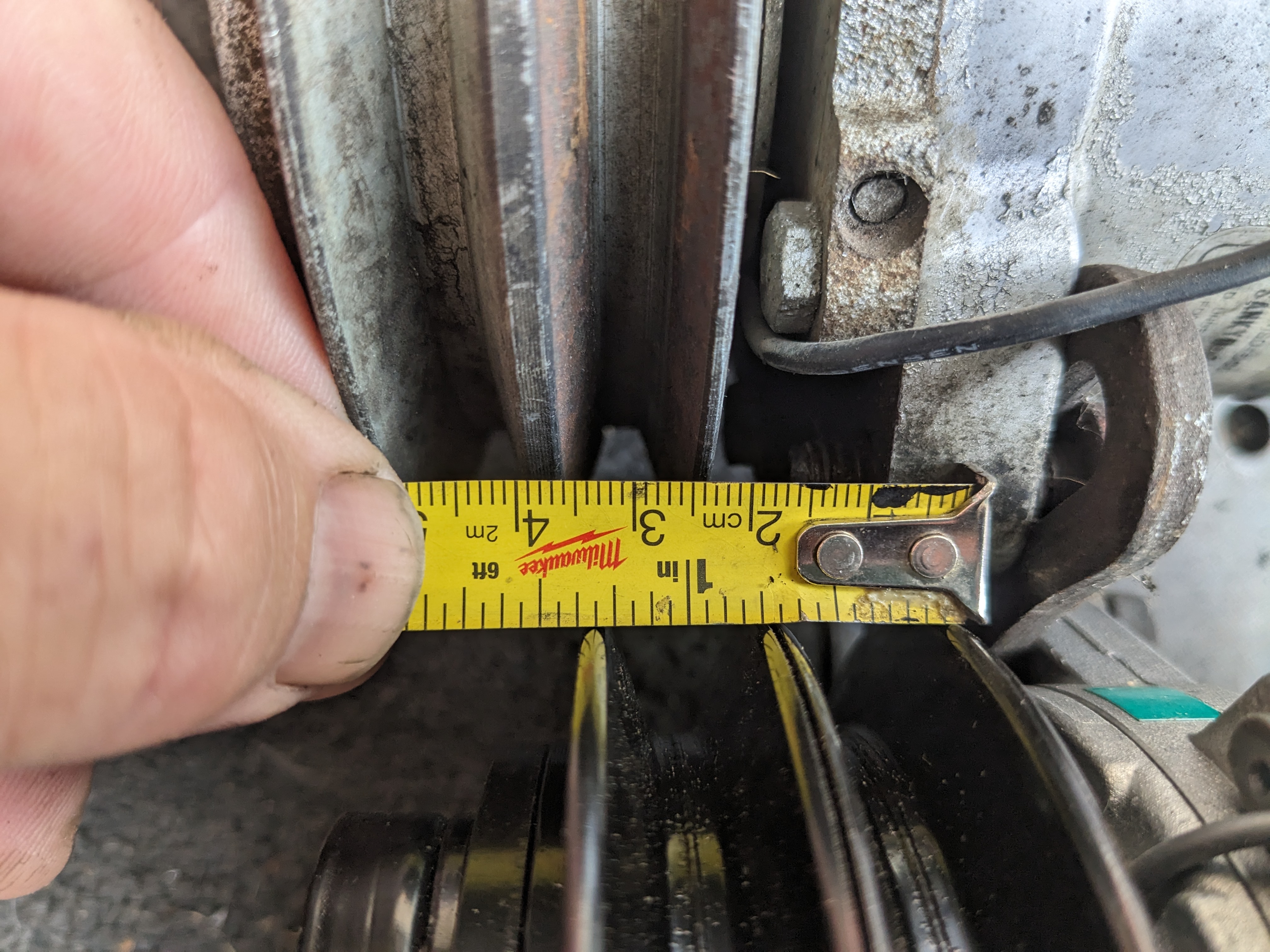
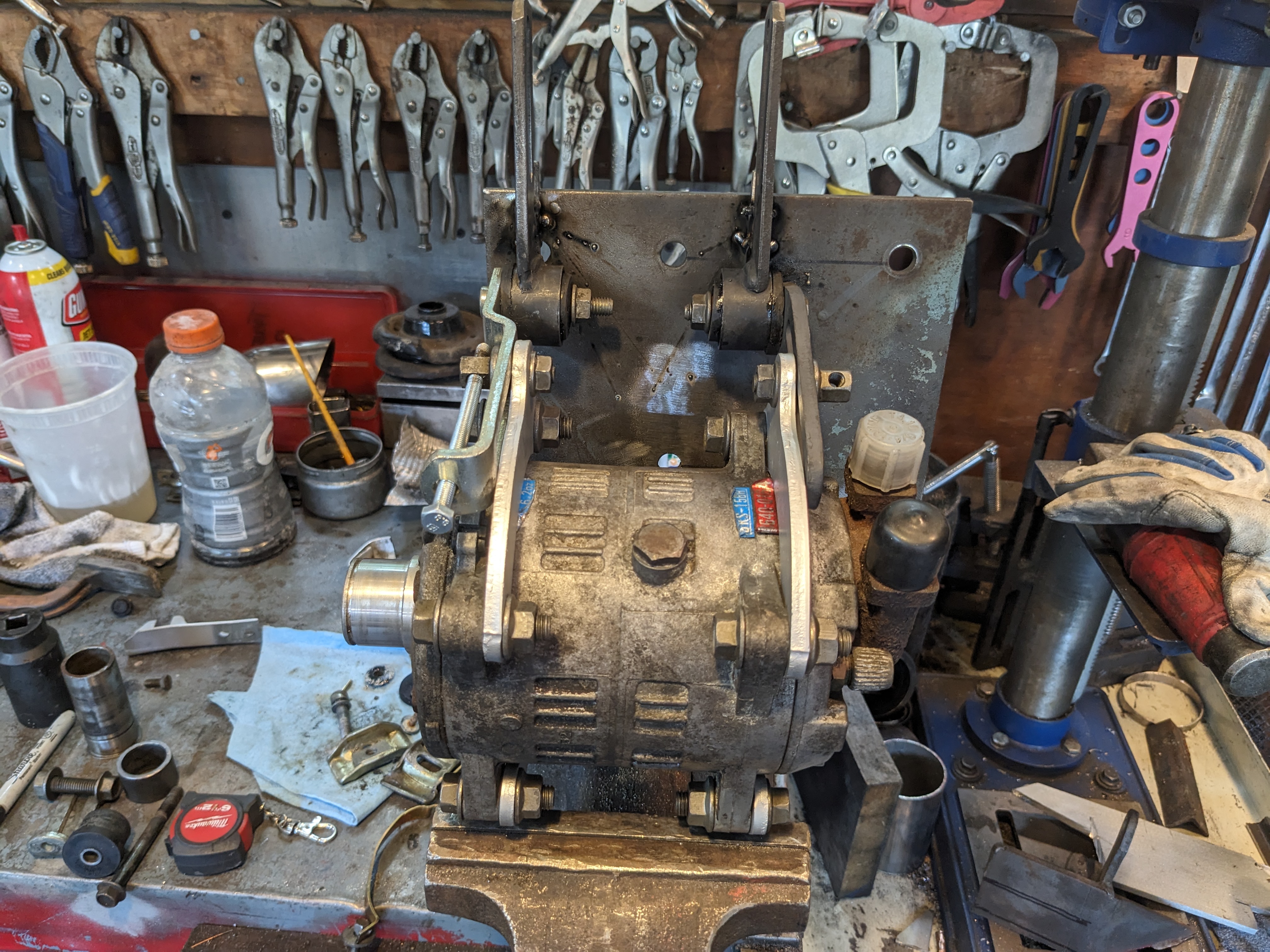
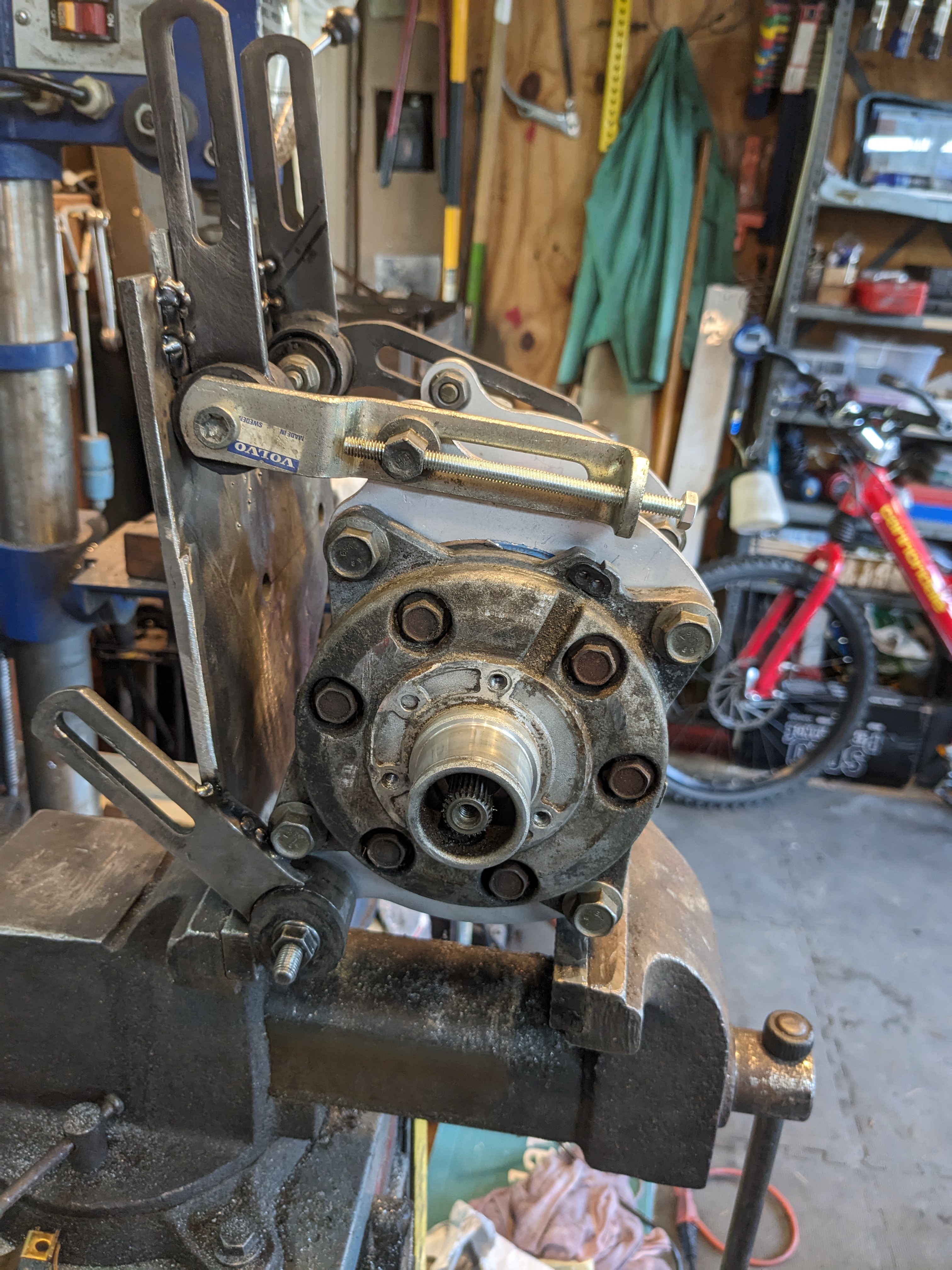
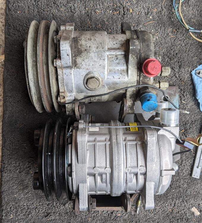
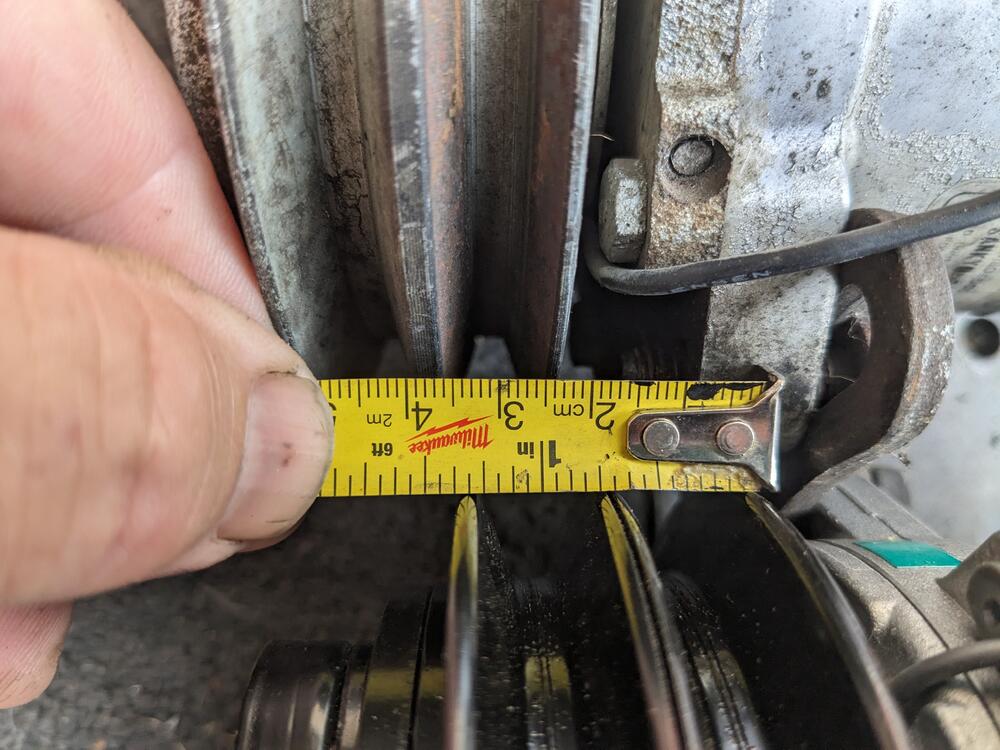
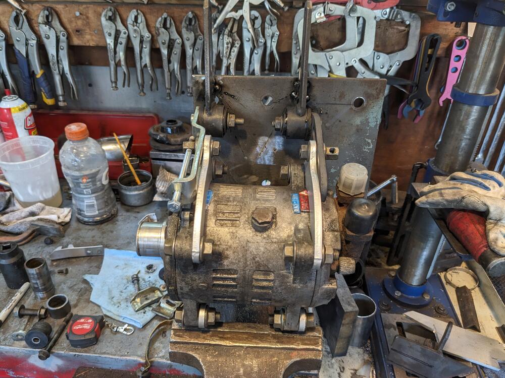
Made the additional support bracket for the heat shield, to account for the additional weight of the accumulator & hoses After that I got started on the AC compressor mounting Datsun compressor on top in stock offset position - I want the new compressor to sit back& use the outer pulley, so I set the new compressor on the inside of the existing bracket to compare offset The belt won't align as is - so I have to move the compressor forward just about a 1/4" inch. That meant I had to cut off the existing bracketry & only made use of the back plate aspect tack welded the Volvo bushing mounts, checking alignment as I went 4 of the five in place - the last I need to have to compressor mounted on new bushings before I weld that one in place
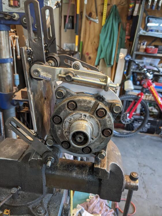
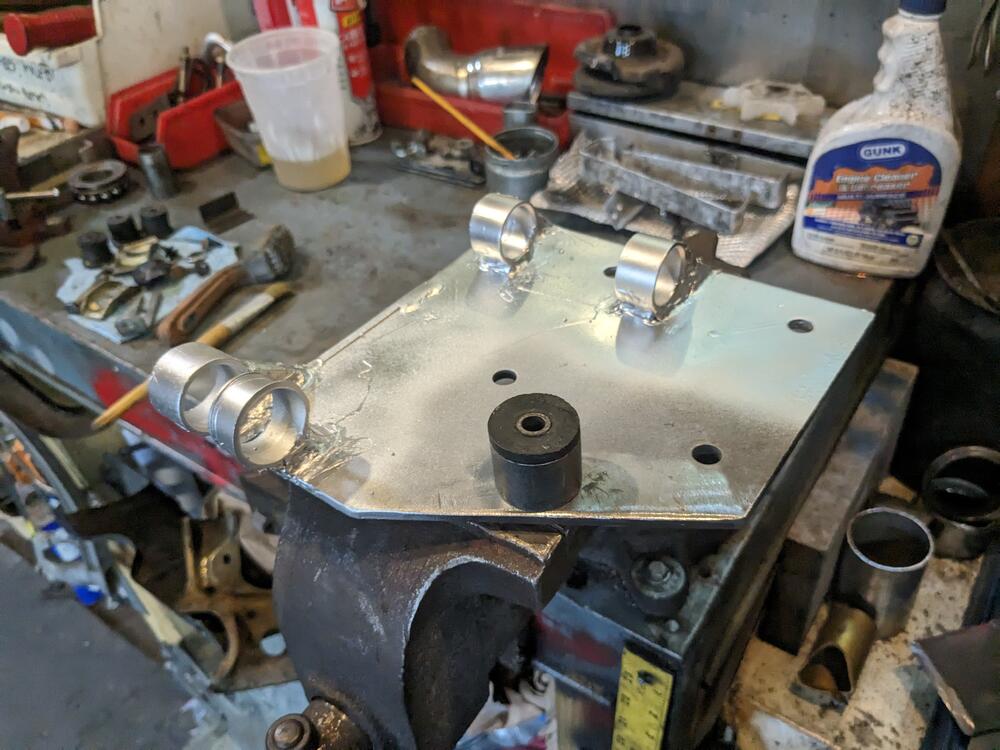
-
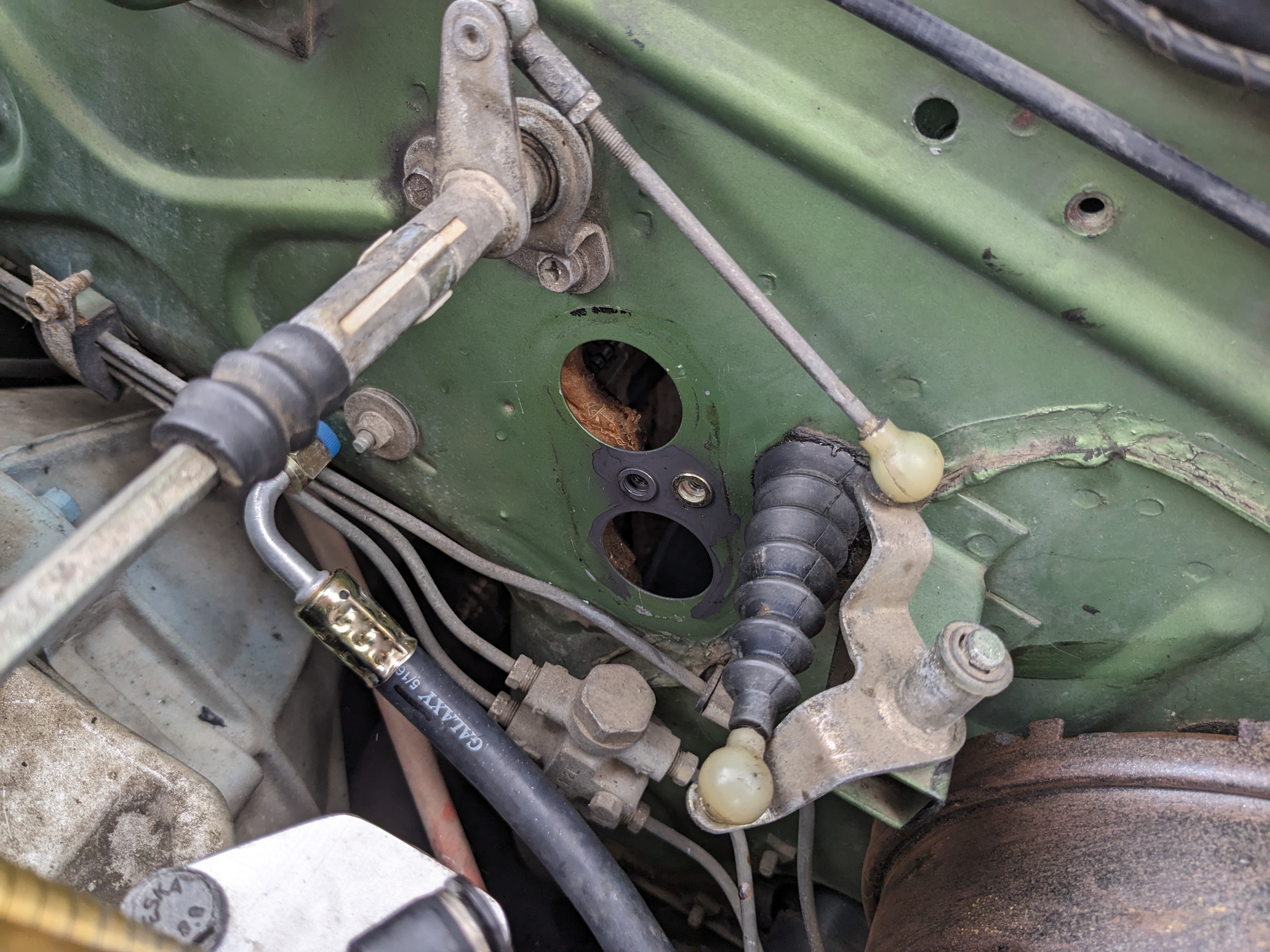
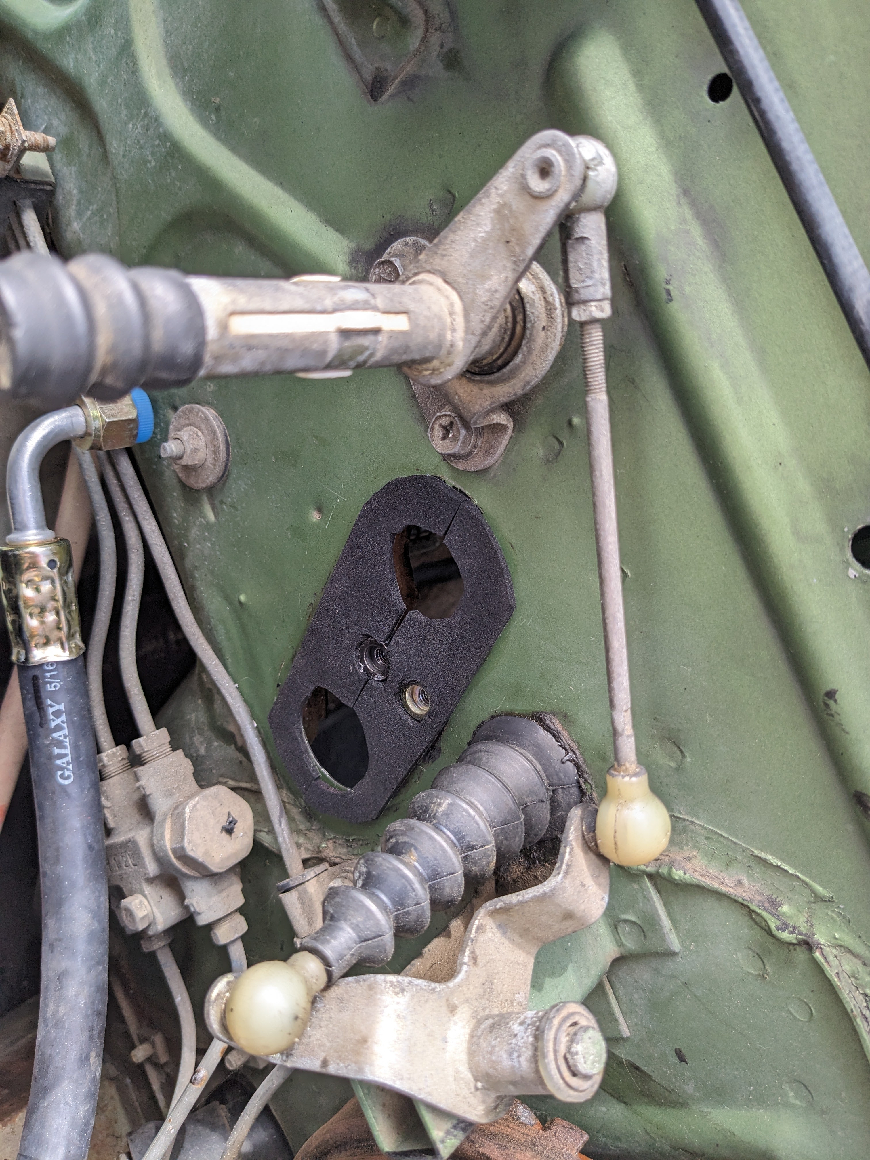
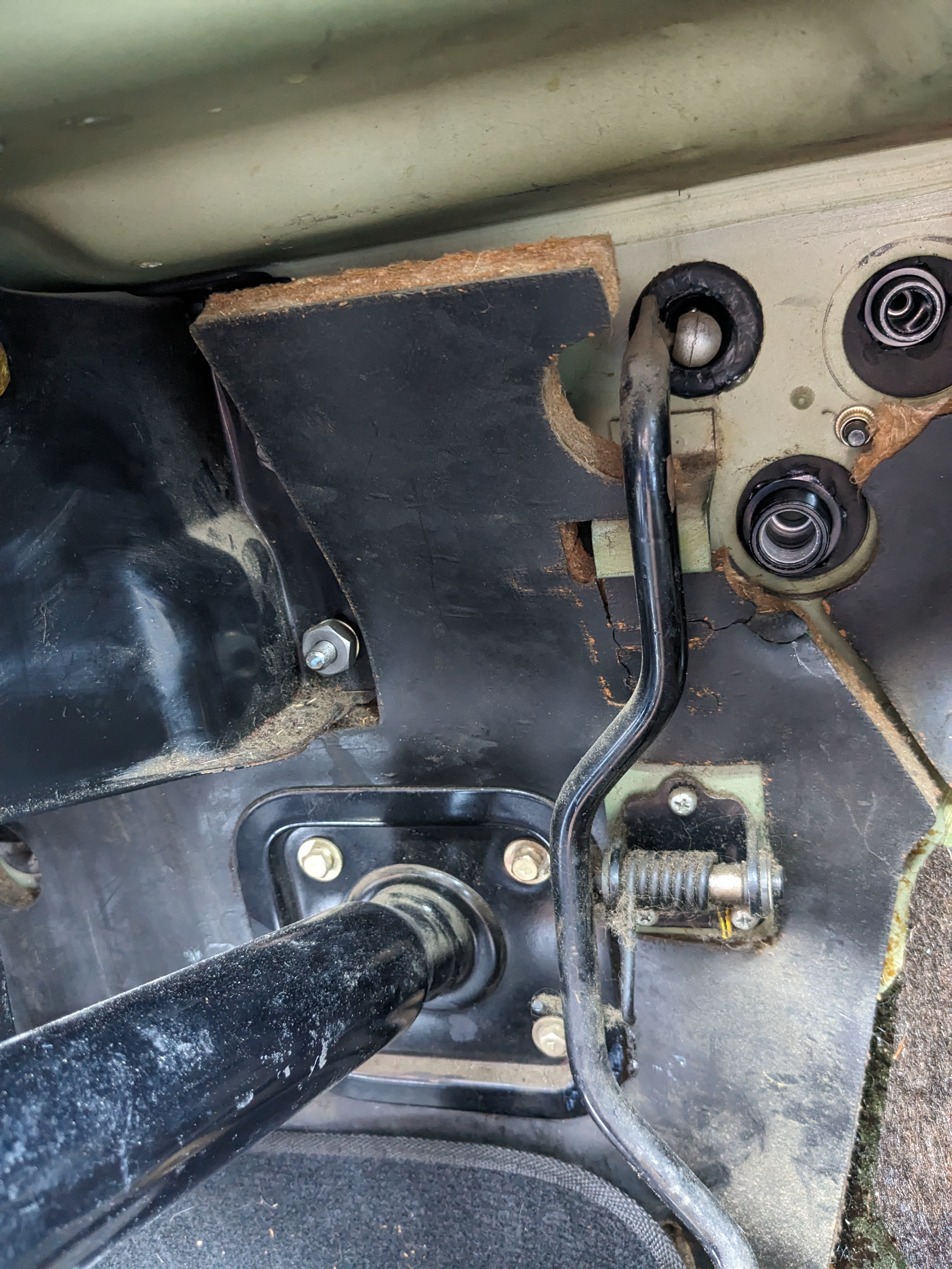
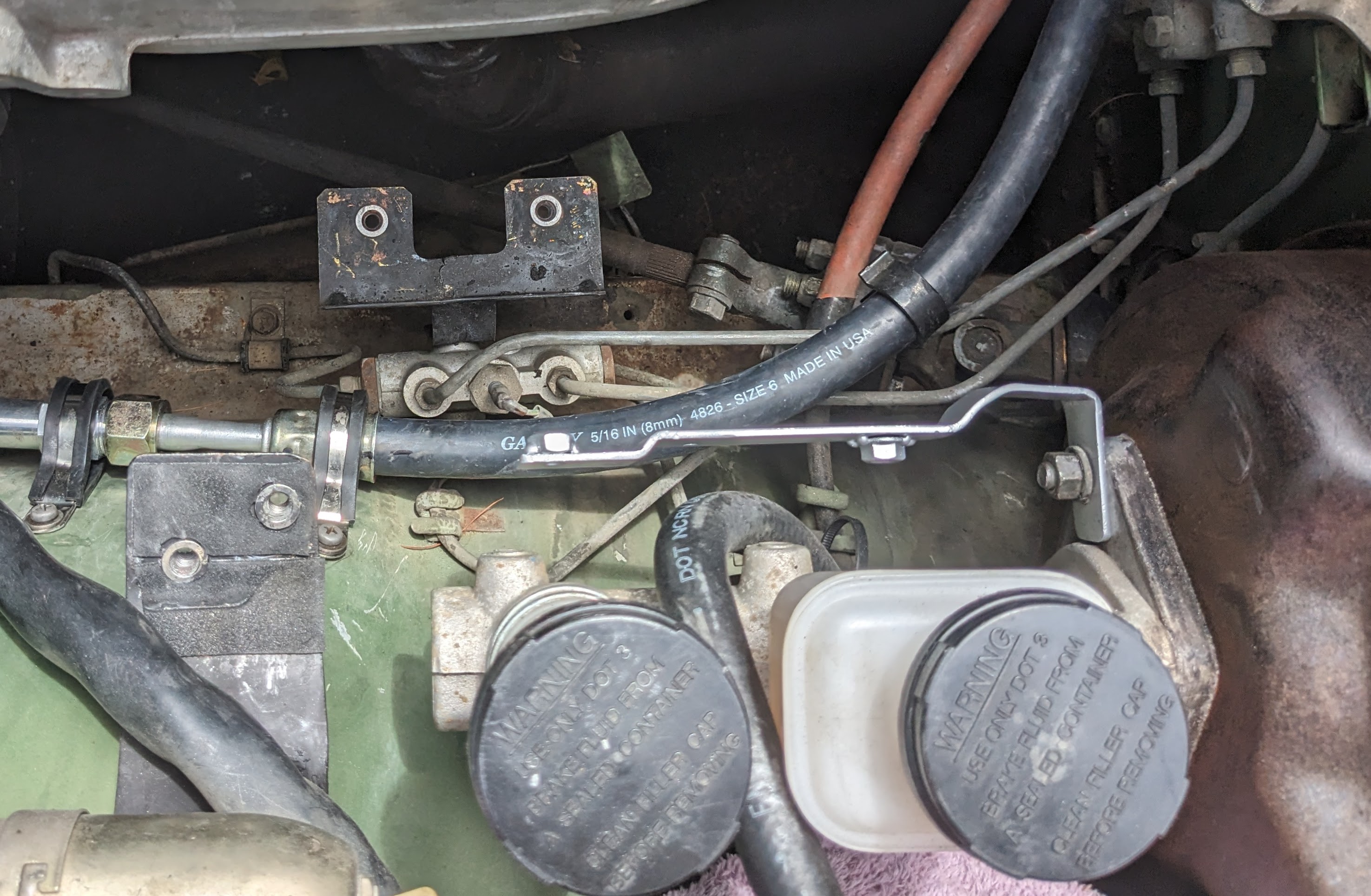
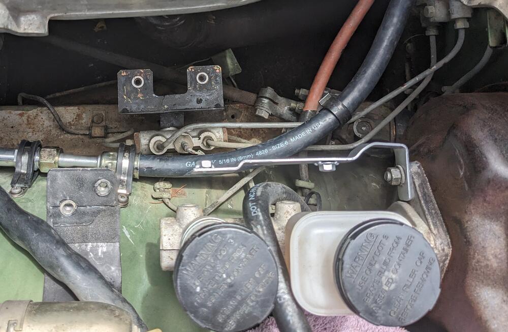
Worked on the AC hose routing & accumulator placement today. The bulkhead fitting was the wrong size, so I had to cut it & add a center section to space it out, used the factory cover plate as the template after welding, cleanup & paint, adding a closed cell foam seal determined the most suitable location for the accumulator. This will likely need revision when the drivetrain swap happens high side hose routing, with orifice tube & trinary switch crimped the line fittings Made the (Volvo) accumulator mount bracket work - modded the brake master heat shield (from a '78) to accept the accumulator bracket Low side hose goes from #12 fitting to #10 line. This is I made years back for the X1/9/Honda setup Made sure throttle link clears the AC hose throughout it's arc of travel bracket needs another support here to prevent unwanted flexing Have to cut up the compressor bracket & rework with Volvo rubber mount isolated ears
-
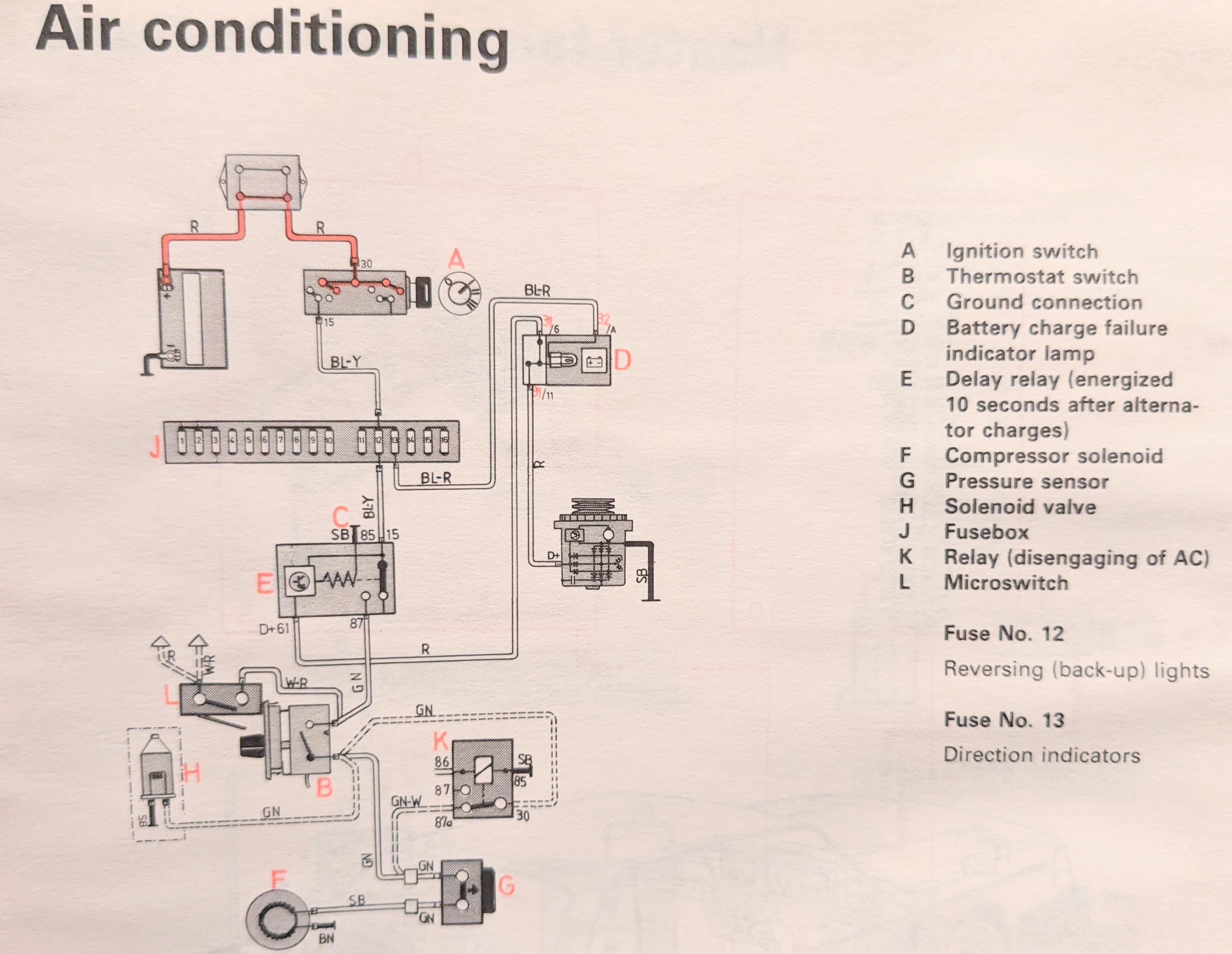
I actually want the 4 speed fan option 🙂 - the after market cut off switch I would then eliminate. The fan I will wire to run at lowest speed when the AC is engaged, like my X1/9 I'm also going to add the delay relay (E, #1363449) that Volvo used in the 80's, prevents the AC running until the alternator is charging. This model also used the same thermostat switch (B) as the aftermarket setup so I will incorporate that

-
That makes more sense. Any chance you have an extra 4 speed switch? 🙂
-
Yeah, it just would make more sense to have a switch that turned the (blower) fan on with AC engagement, rather than one than disables the AC thermostat if it's NOT on. Do you know if the fan speed resistor is different for AC models? I'm wondering if it's worth playing with differing fan speeds than provided.
-
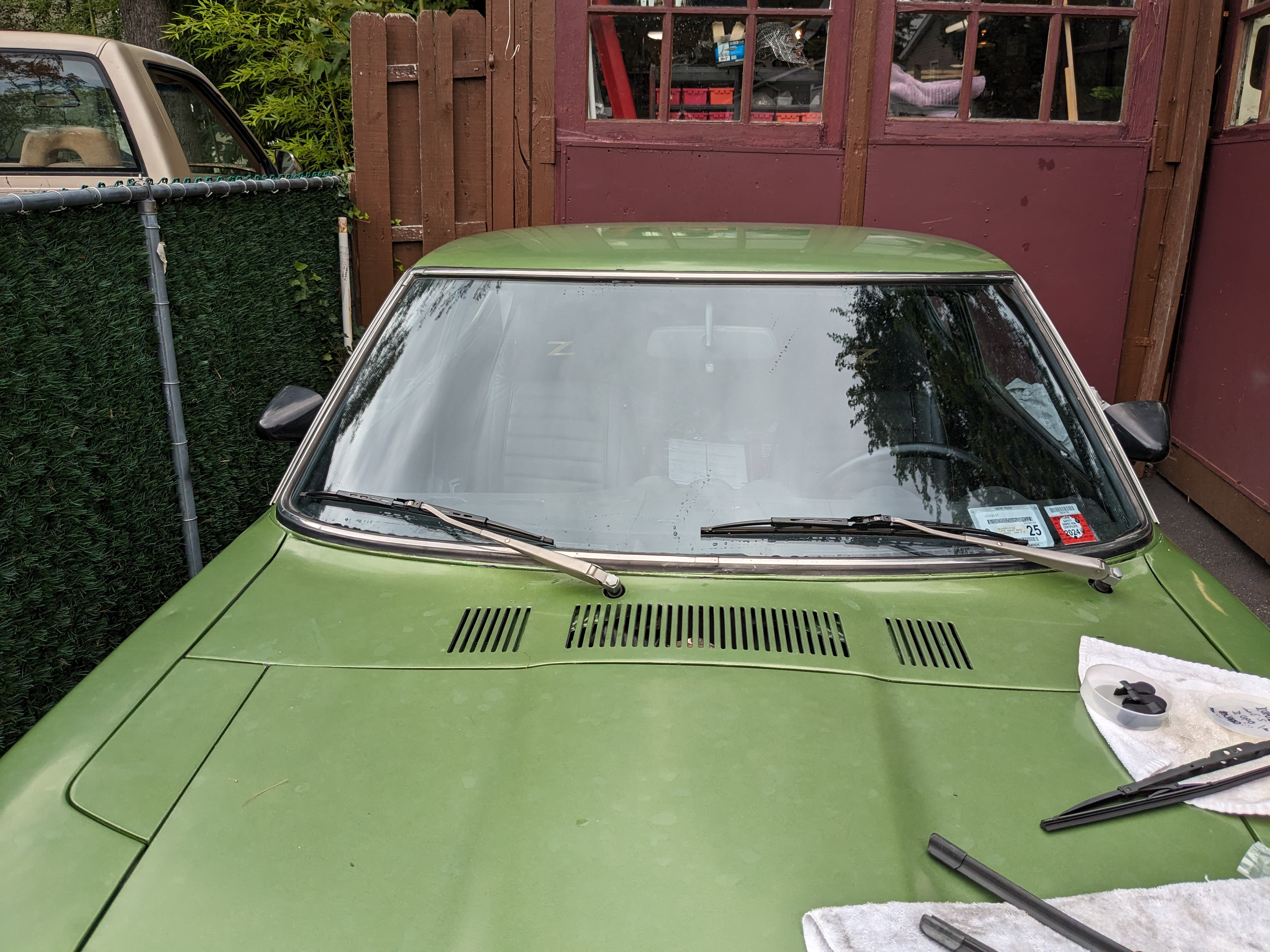
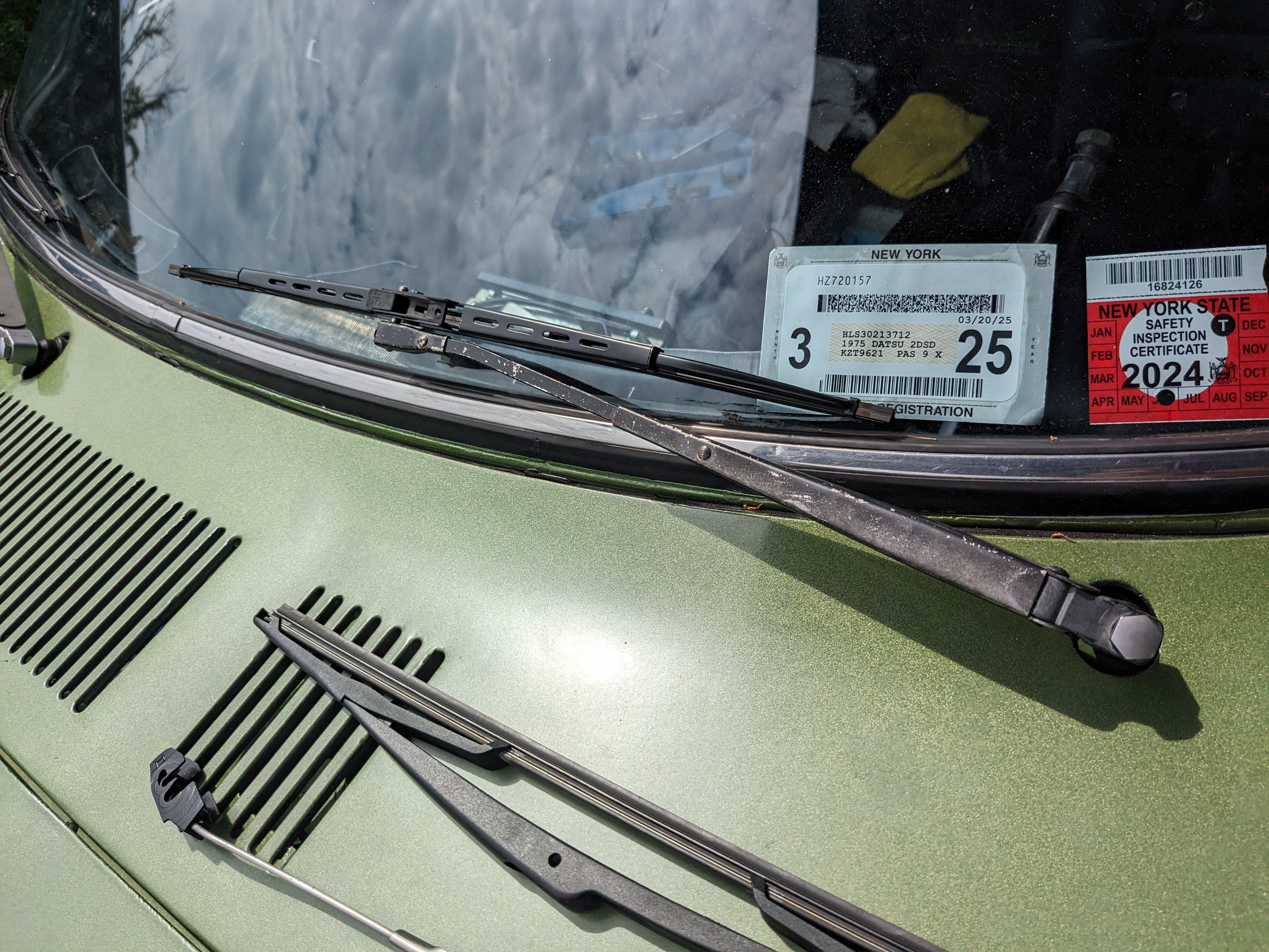
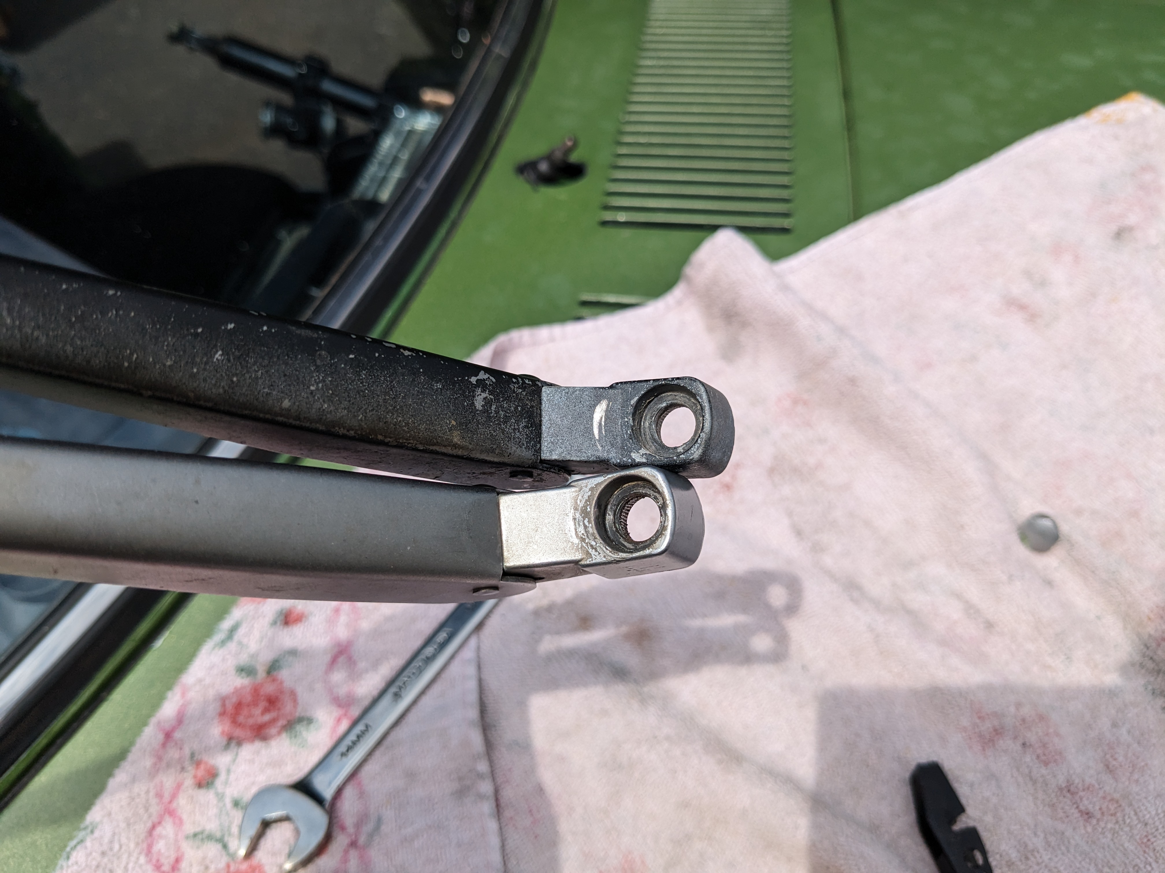
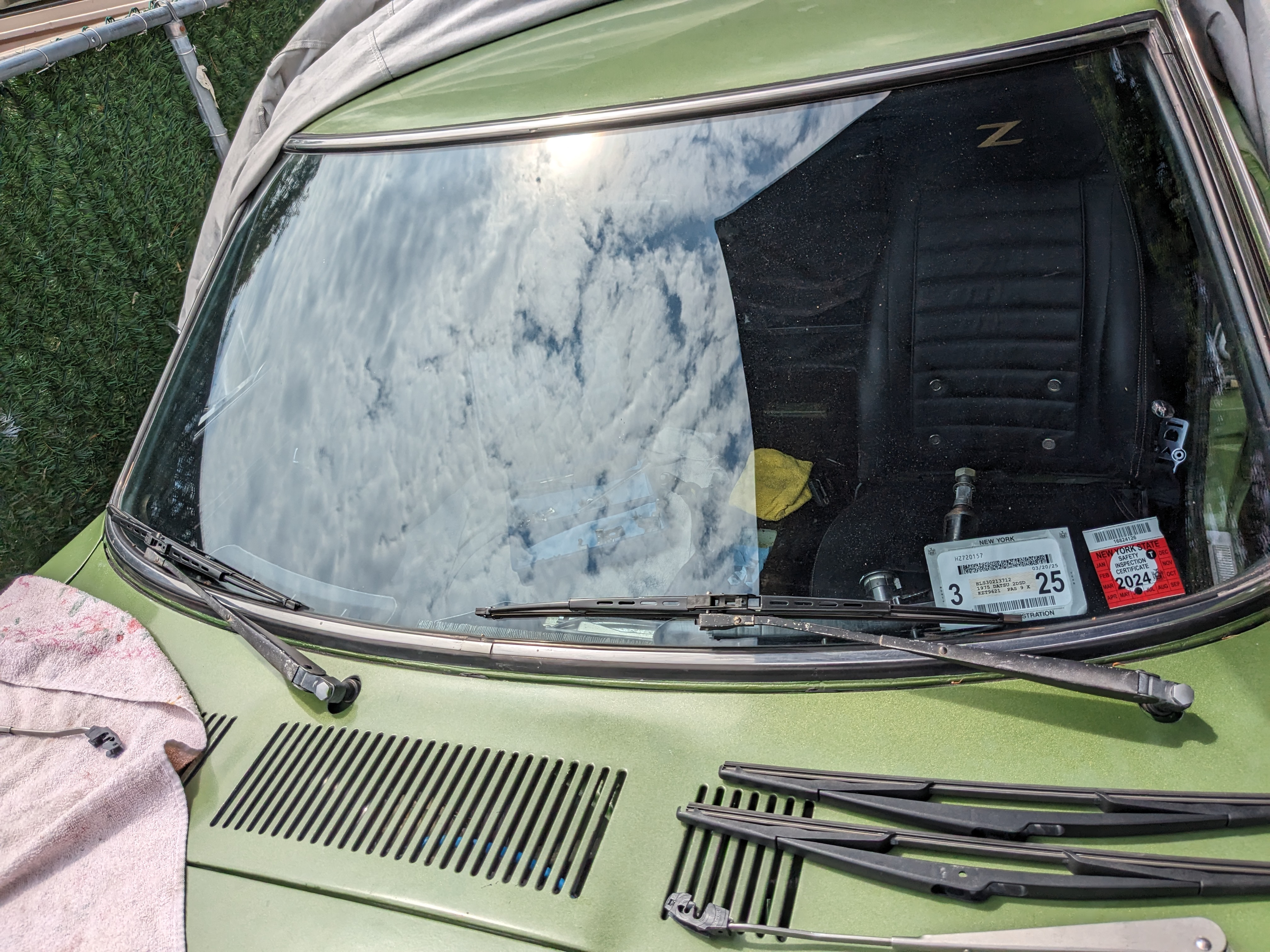
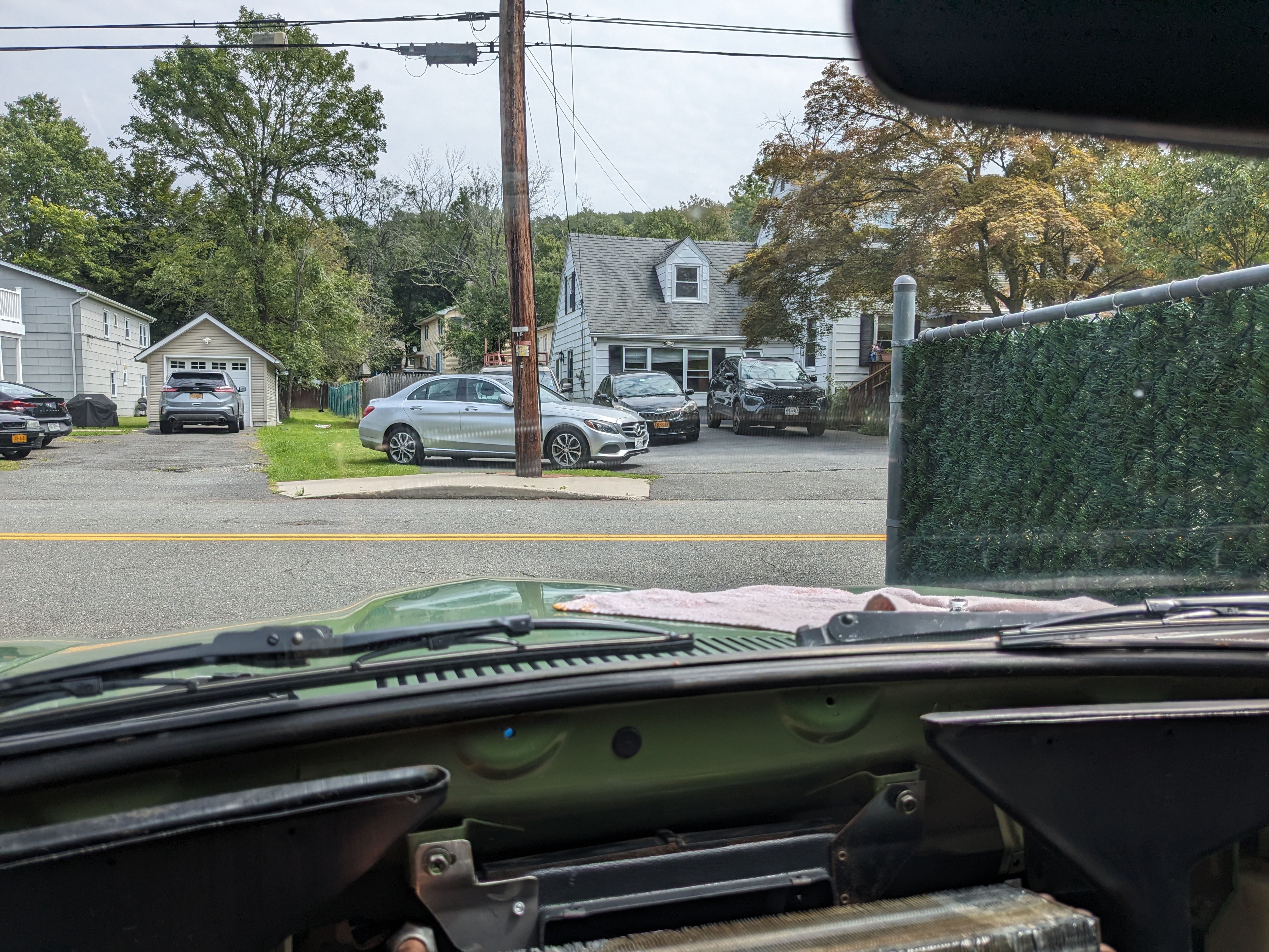
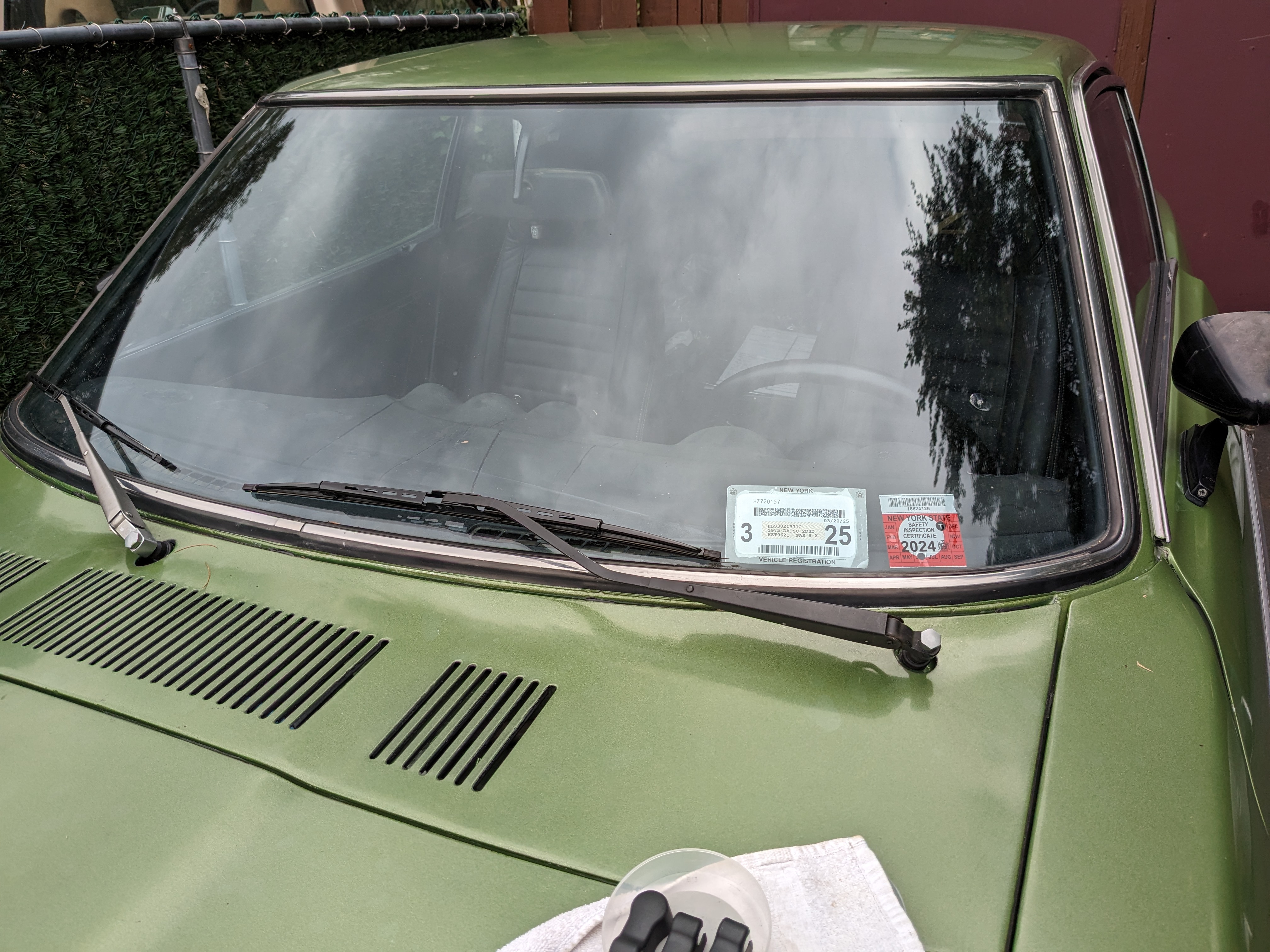
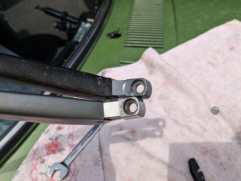
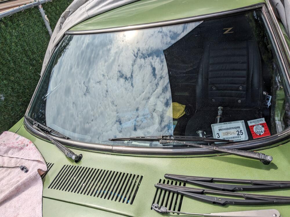
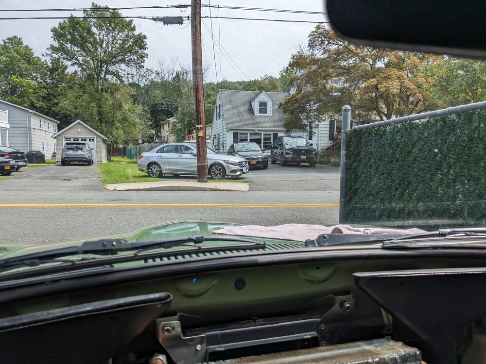
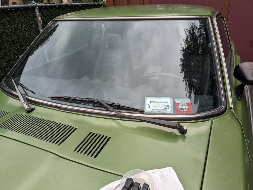
Now that I have the dash out & easier access to all the fuse/relay panel wiring, I'm going to revisit the interval relay. The other thing I disliked about the wipers is how high the arms & blades sit - when I'm driving the blades/arms interfere with seeing the nose of the car. So, I tried doglegging the stock arms to drop them - that did work to some extent, but not ideal. I also tried doglegging the arms off of a Volvo 240, that was better. Then a friend found arms intended for a 240 that are made in Japan (Trico, like the OEM), so the base mount is identical to the Datsun arm, however the blade attaches to an offset pin instead of to the arm directly. That allows the arms & blades to sit lower than the other options I've messed with. Much happier now Factory, doglegged, 18" blades (Bosch) 240 arm, doglegged (Trico) 240 arm (left) base comparison Just have to refinish them view of hood
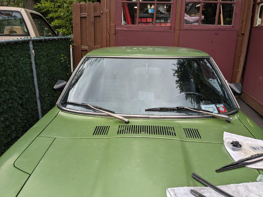
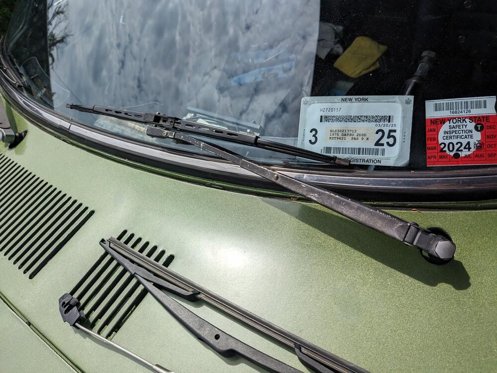
-
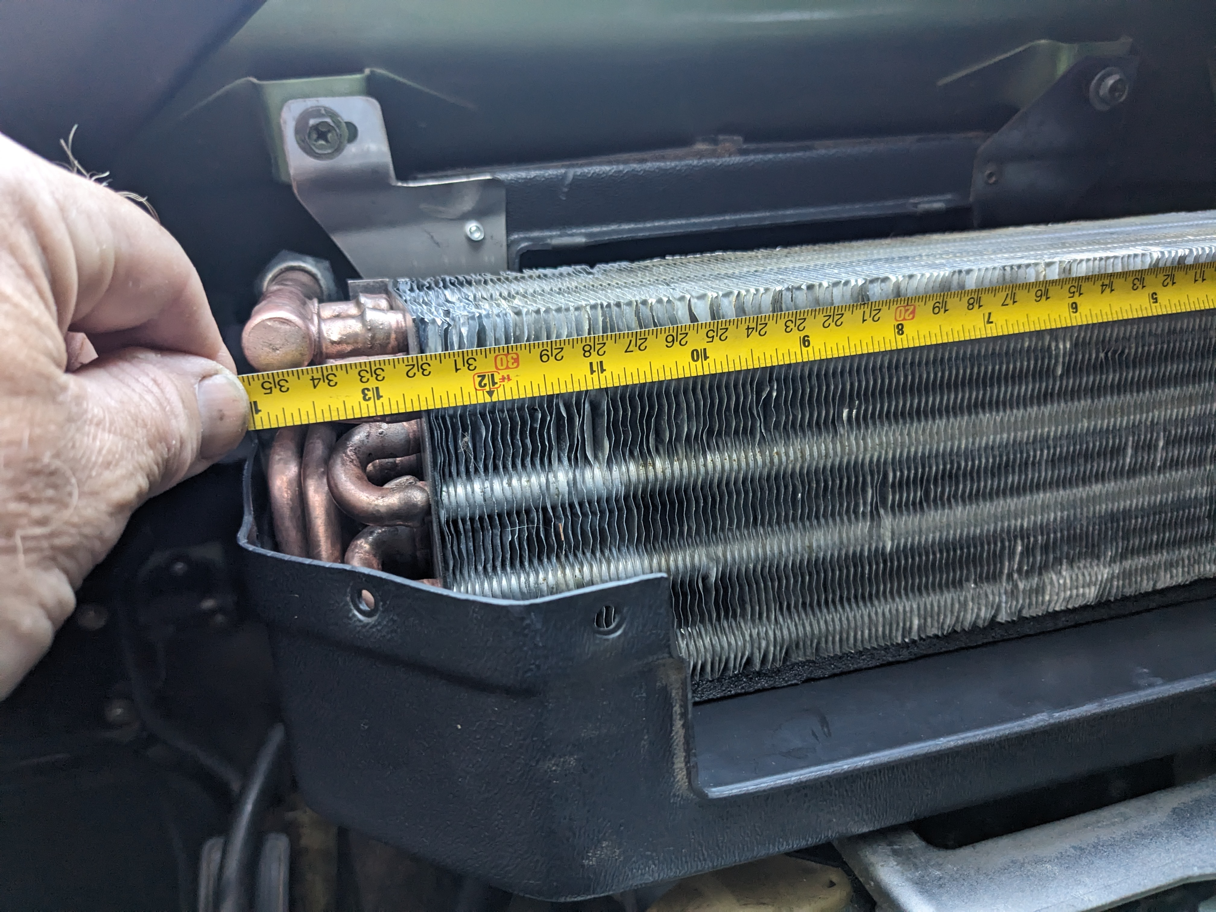
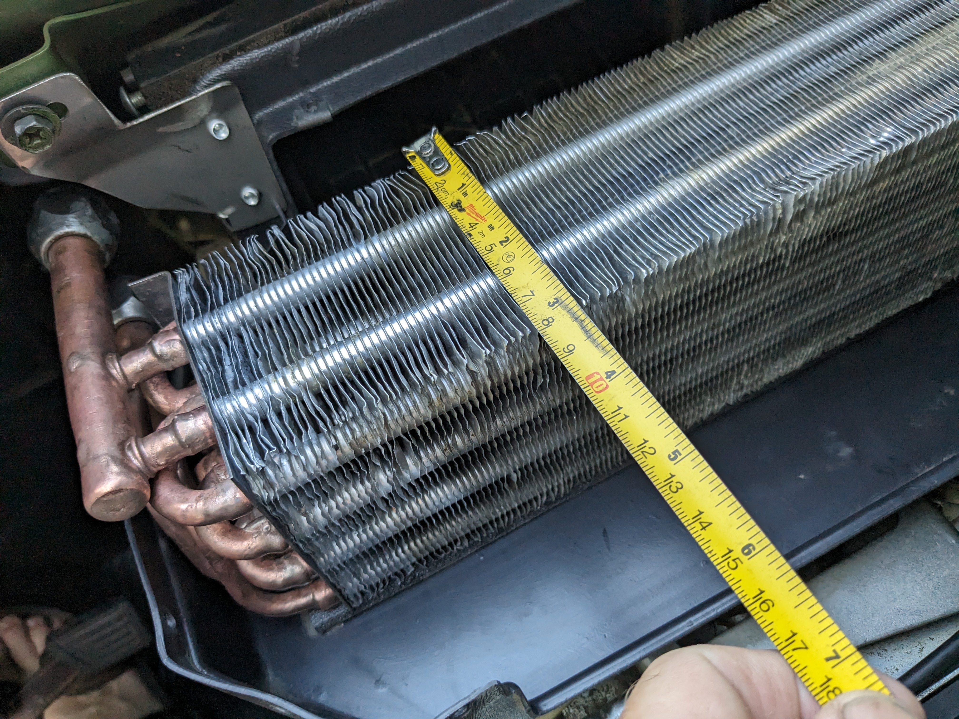
I was wondering how it compared to factory. It's 14"x3"x4" -so 168 cu. In.
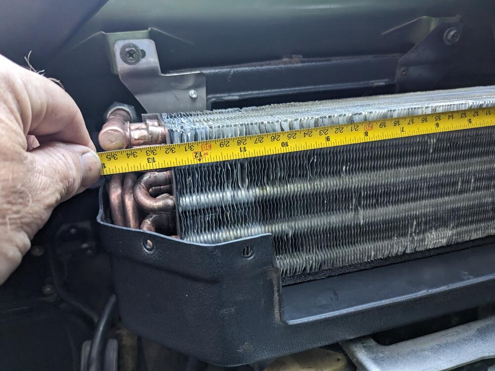
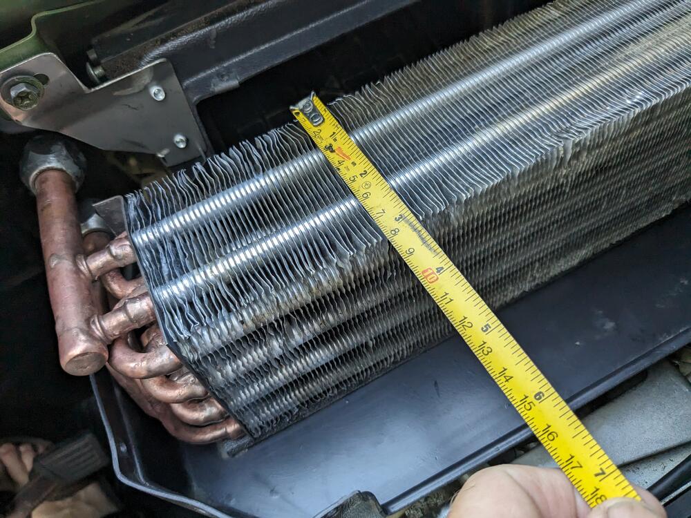
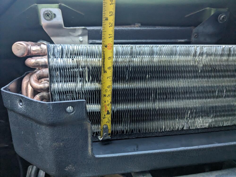
-
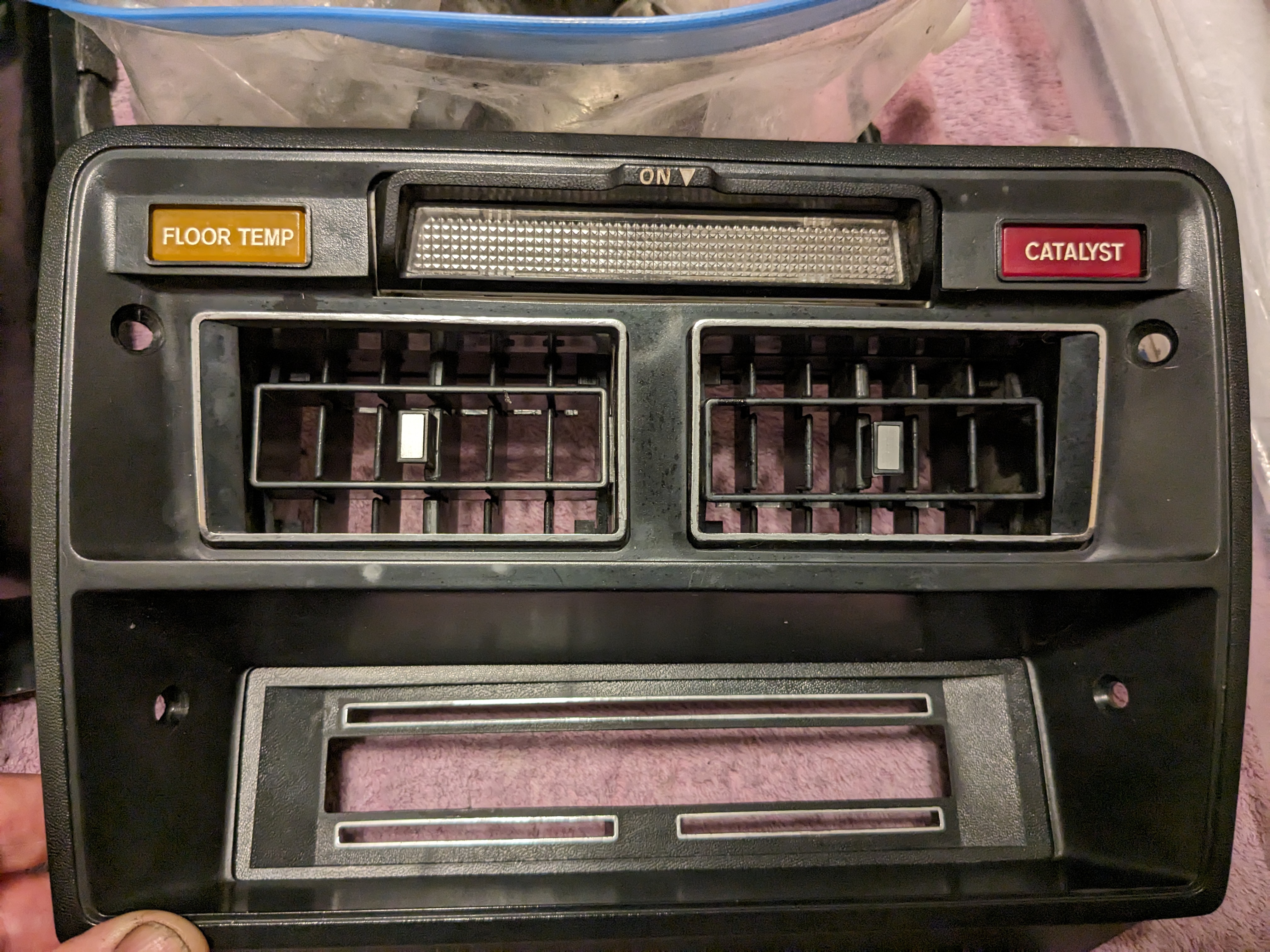
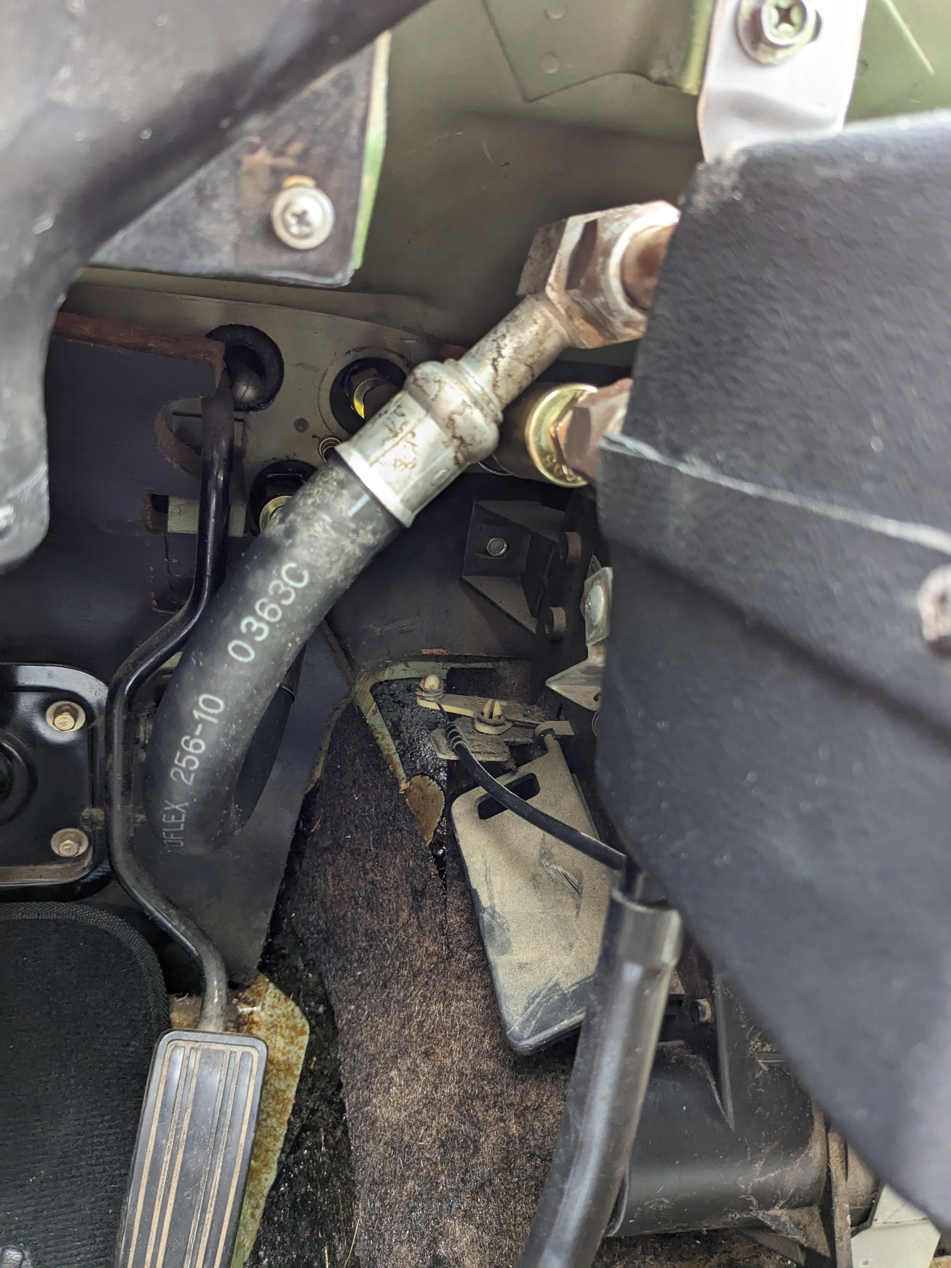
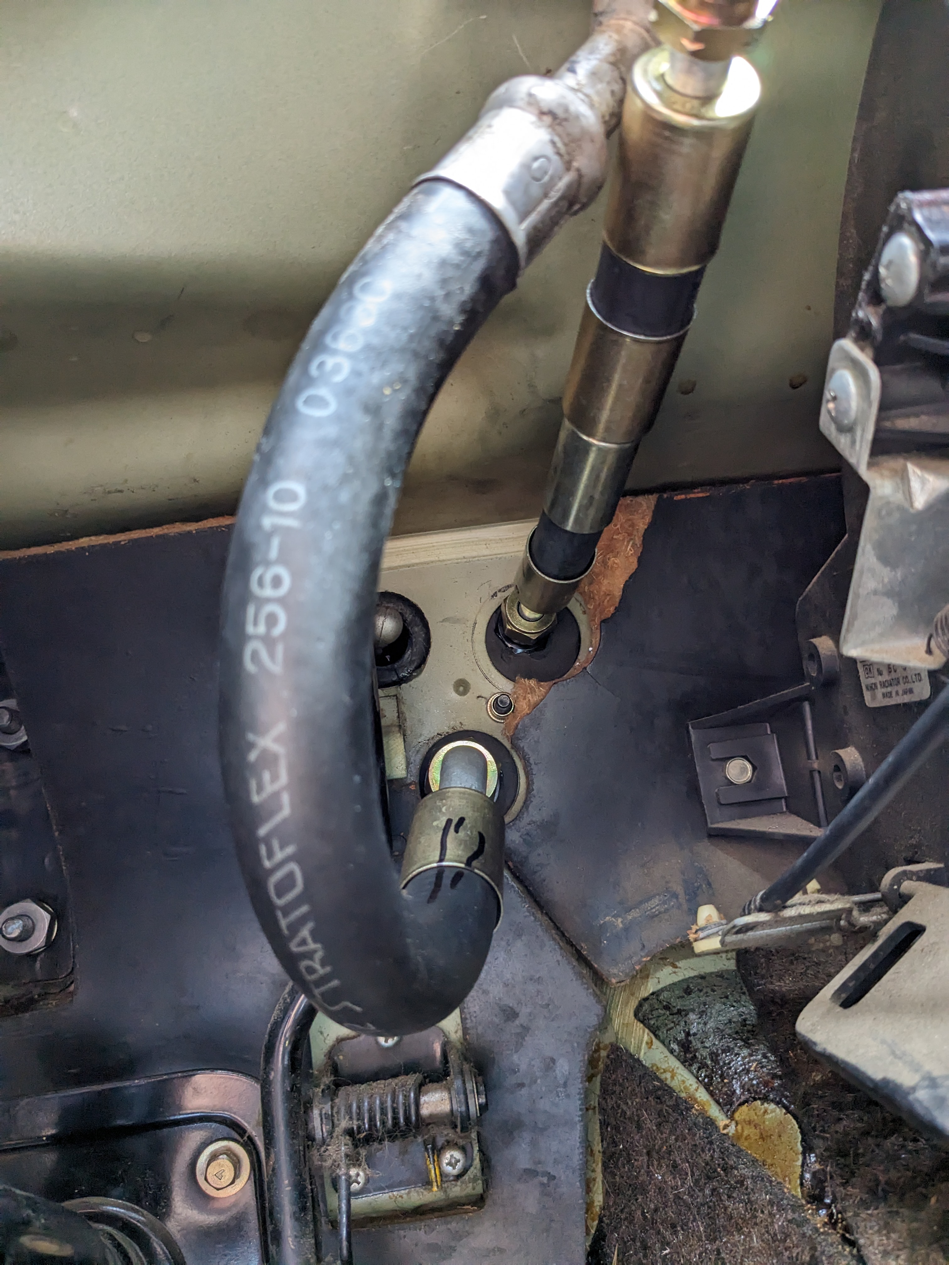
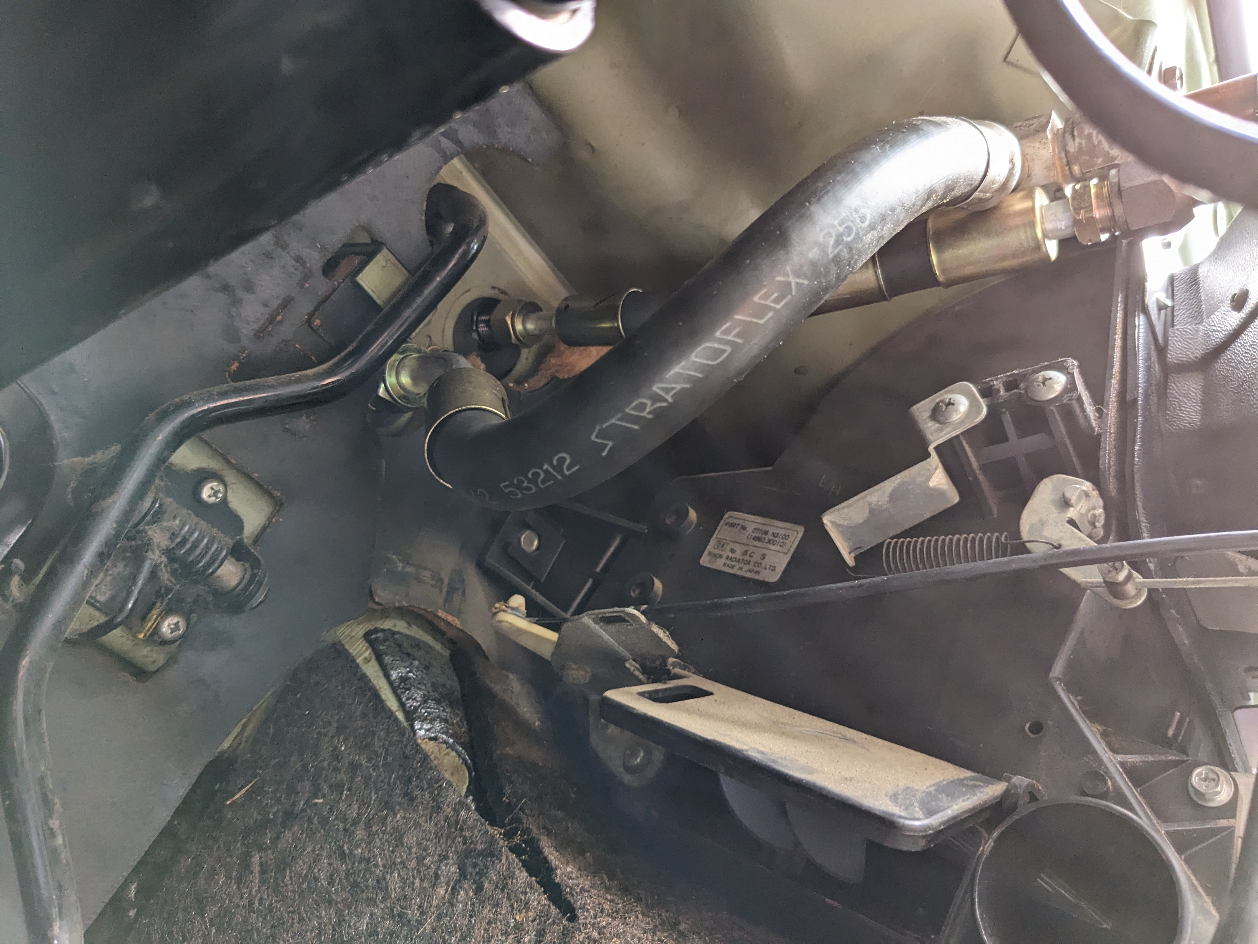
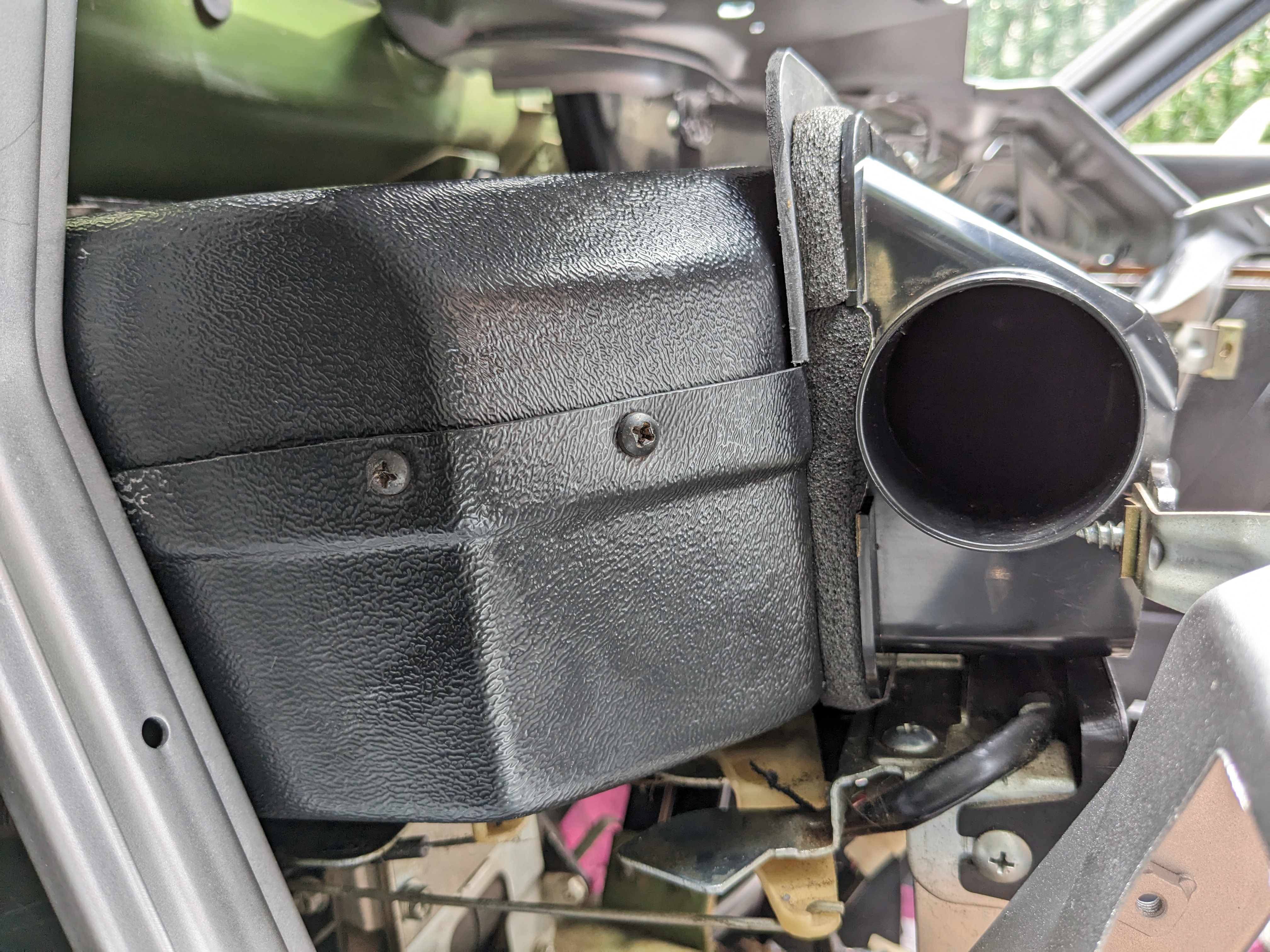
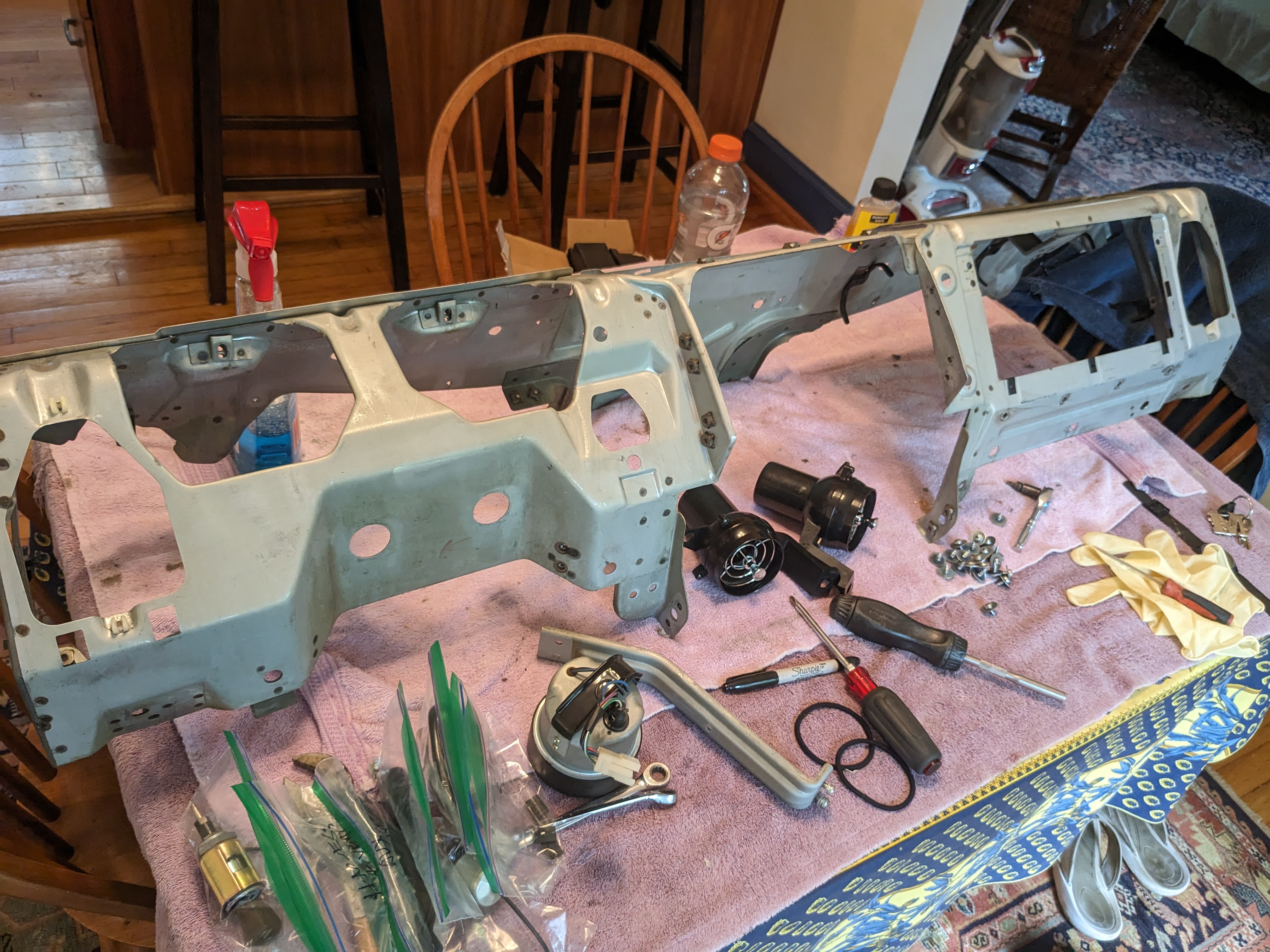
Took the dash out today, to deal with the aftermarket AC work Yuk - 48 years of dust & dirt Dash is actually easy to remove - entire harness unplugs on the pass side, and then just a few connections on the left side of dash. I found it to be very heavy though! I also flushed all the ductwork and tubing, however I'm going to put new tubing in. No way to get all the kaka out of the old ones, and I don't want to be blowing all that crud into the cabin. New dash will go in after all this After several go arounds with sponge, soap & water more yuk made a left side support bracket for the housing plate - the whole thing was hanging off the right ear Evaporator has flare fittings. I've order a #8 & #10 straight flare, and a #8 to #6 step barb Tried fitting the existing hoses to see if I can cut them down - they only need to go to the bulkhead, but the #10 has a 90º elbow, so the routing is very untidy, and the #6 goes to the (now hollowed out) expansion valve, but it's still unwieldy so I'll just make new ones with cleaner routing I found these were mounted under the hVAC control panel - added to control the aftermarket AC thermostat & fan(?) The left one responds to fan position, the right responds to temp setting . I don't have a wiring diagram, so I'm not sure why they added them, honestly.
-
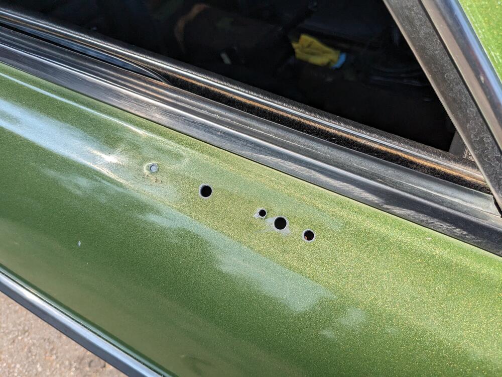
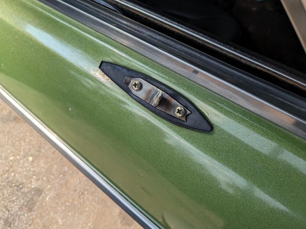
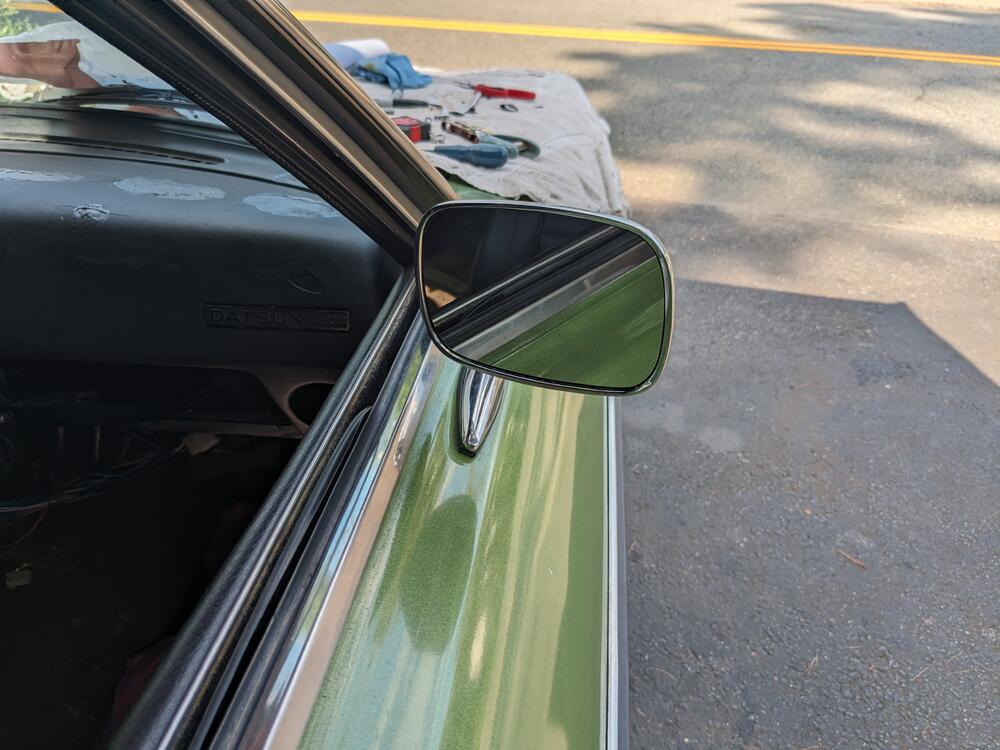
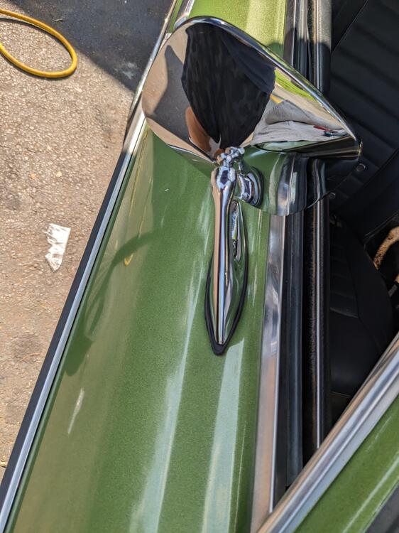
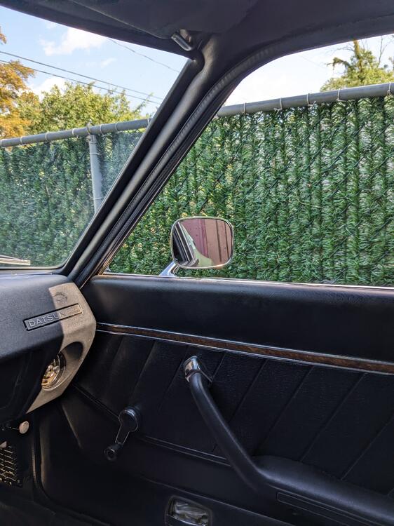
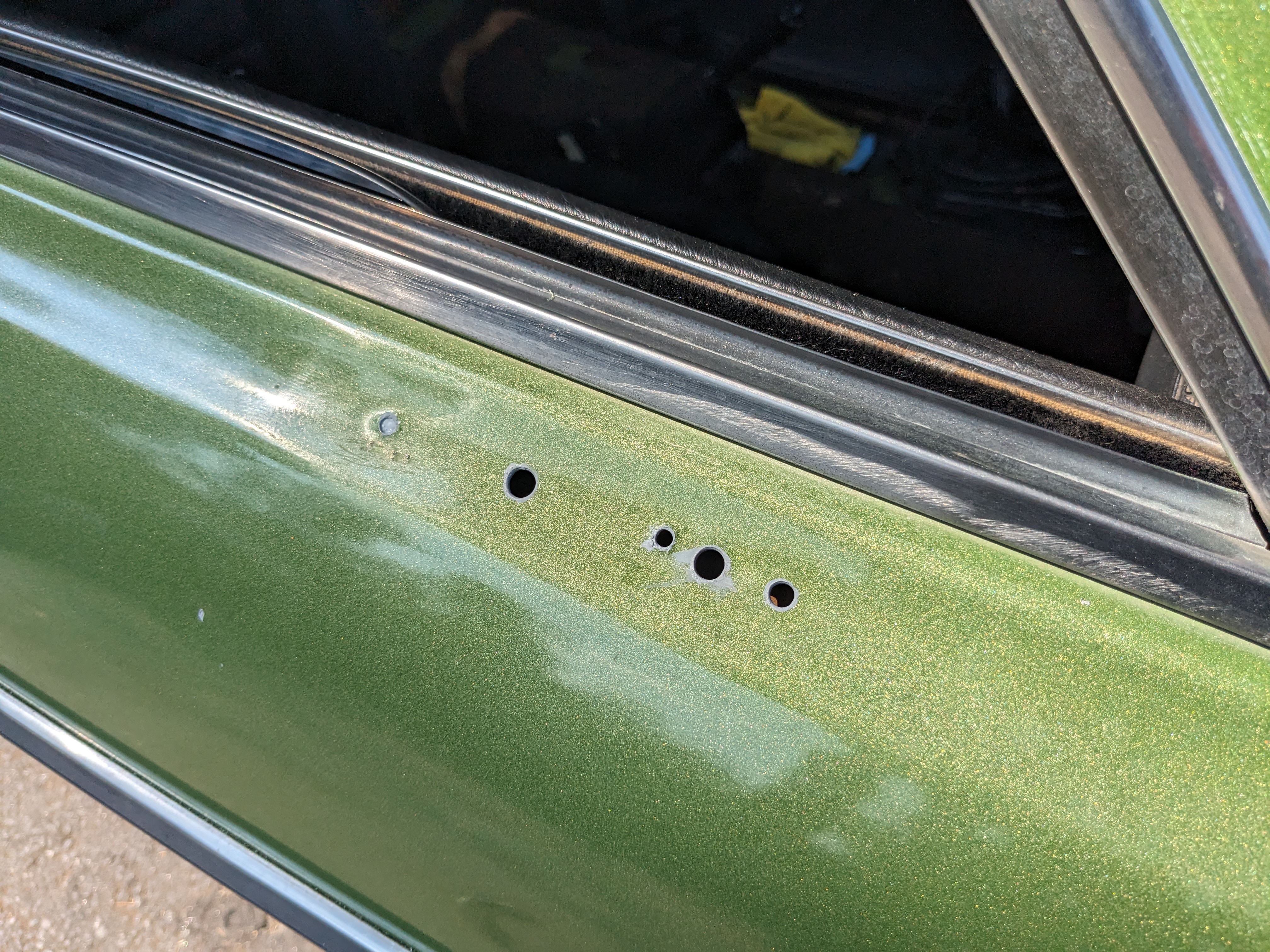
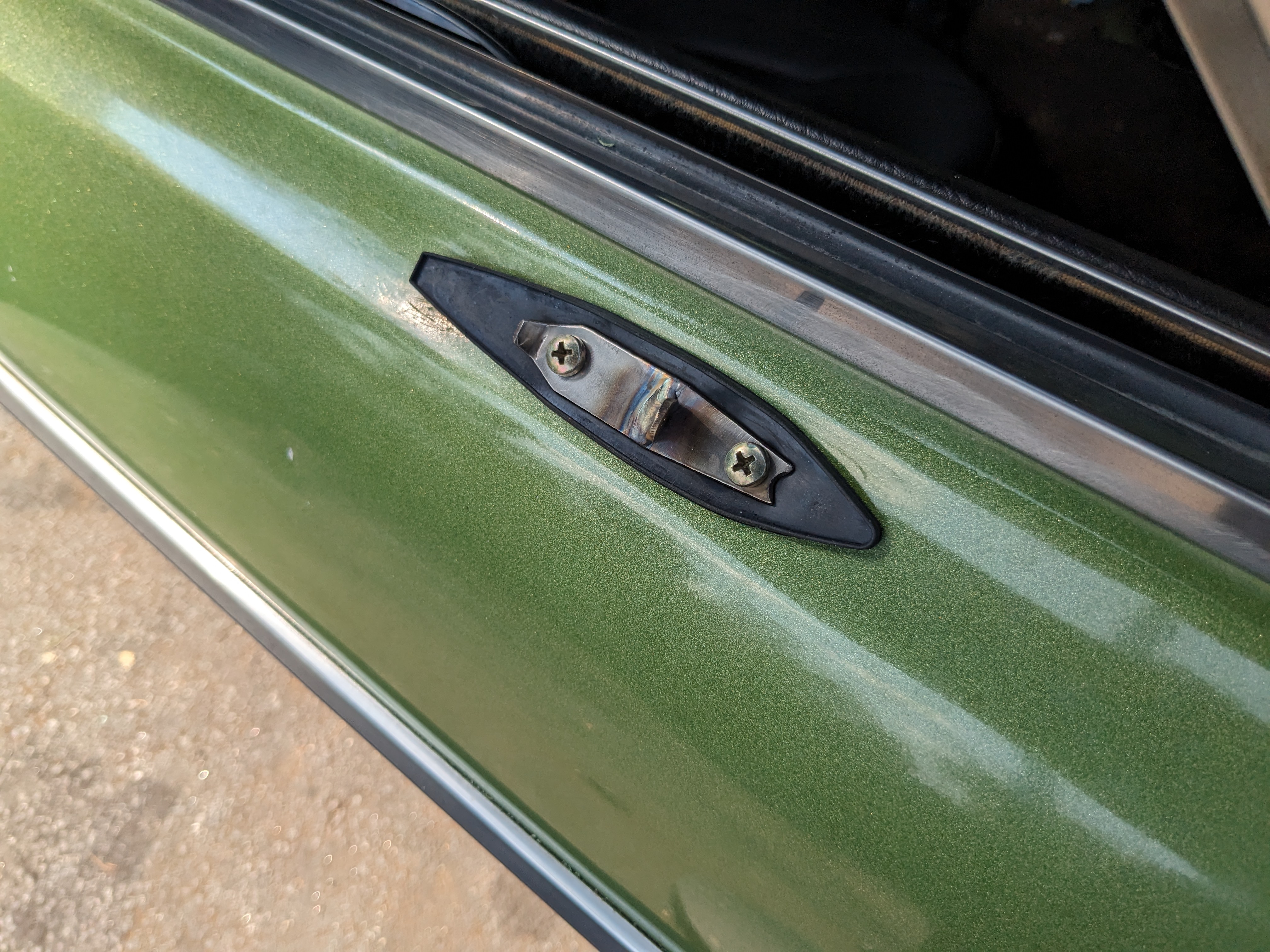
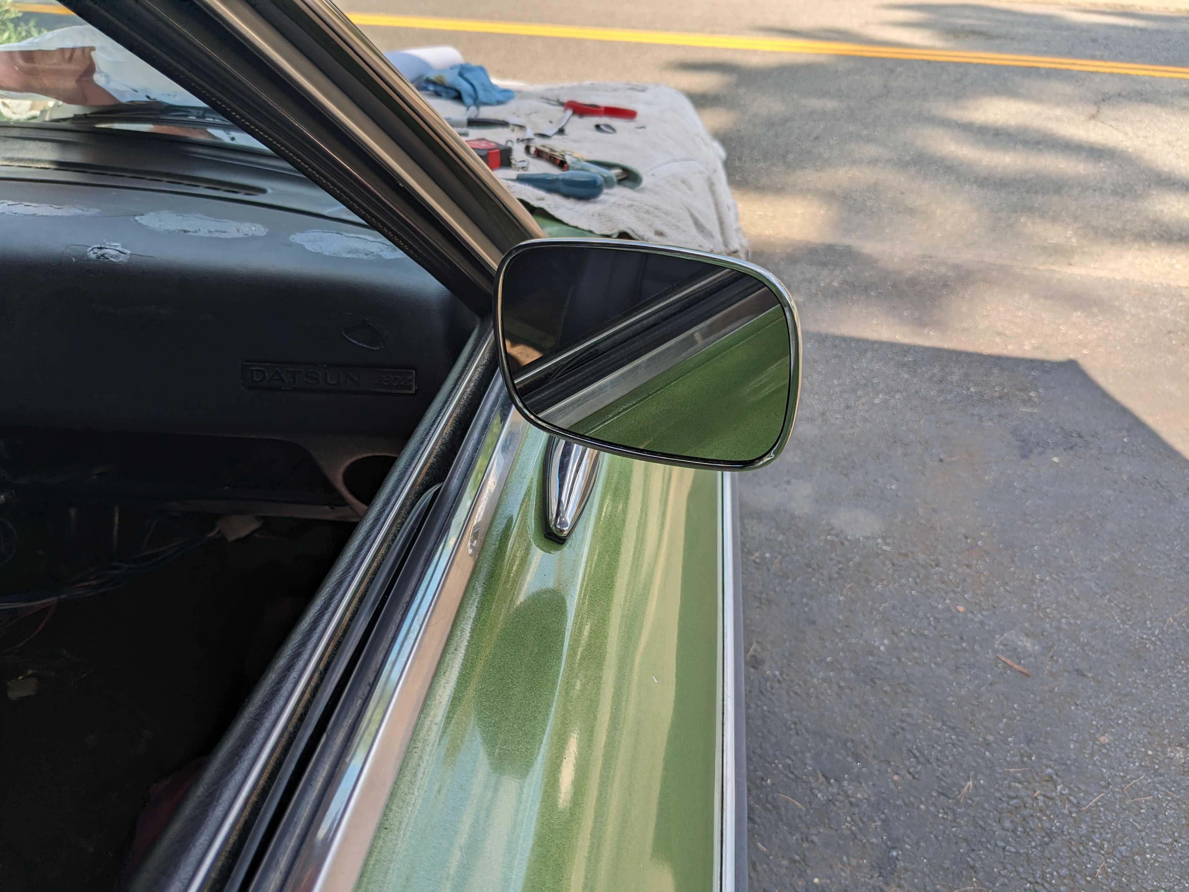
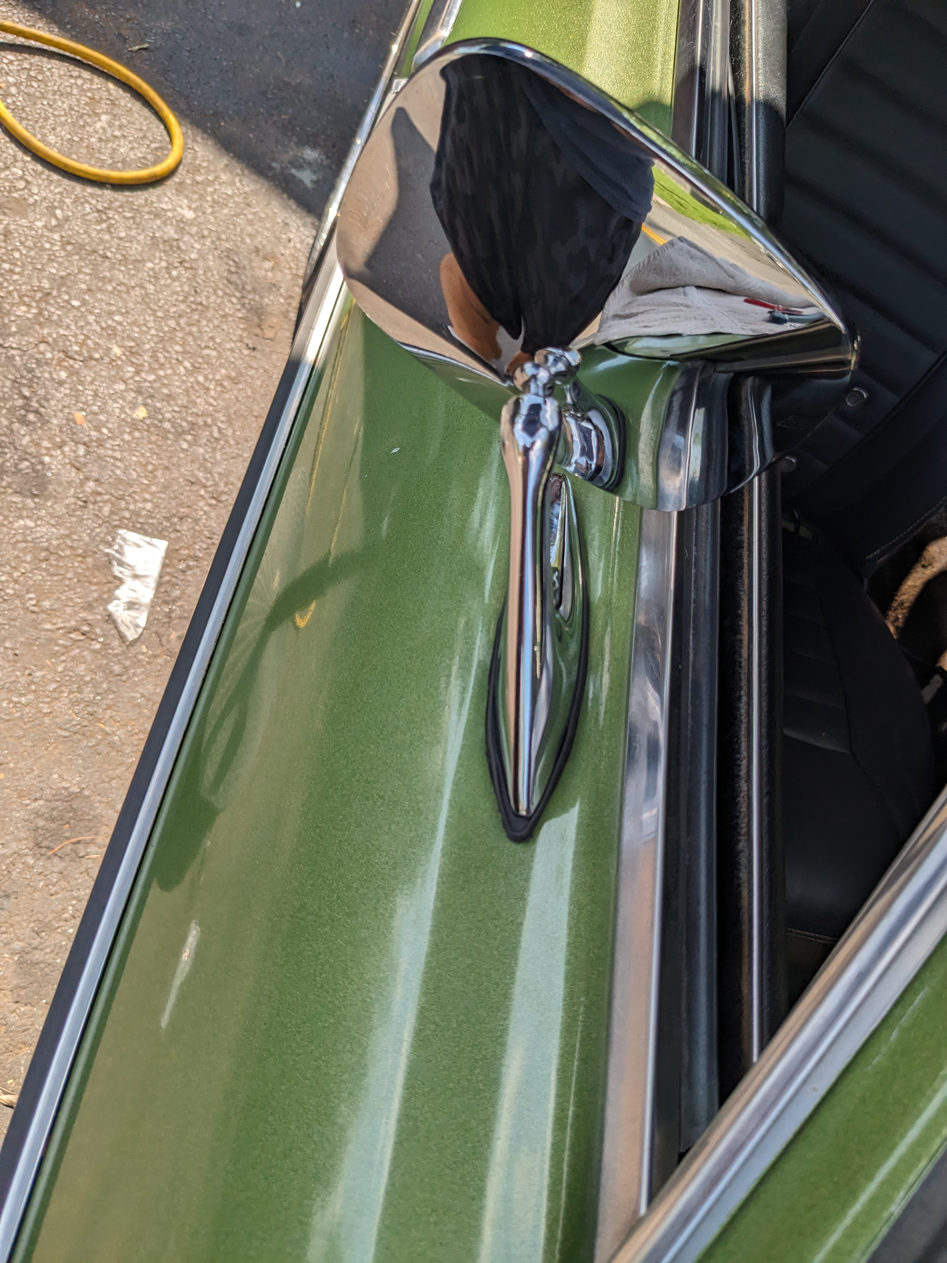
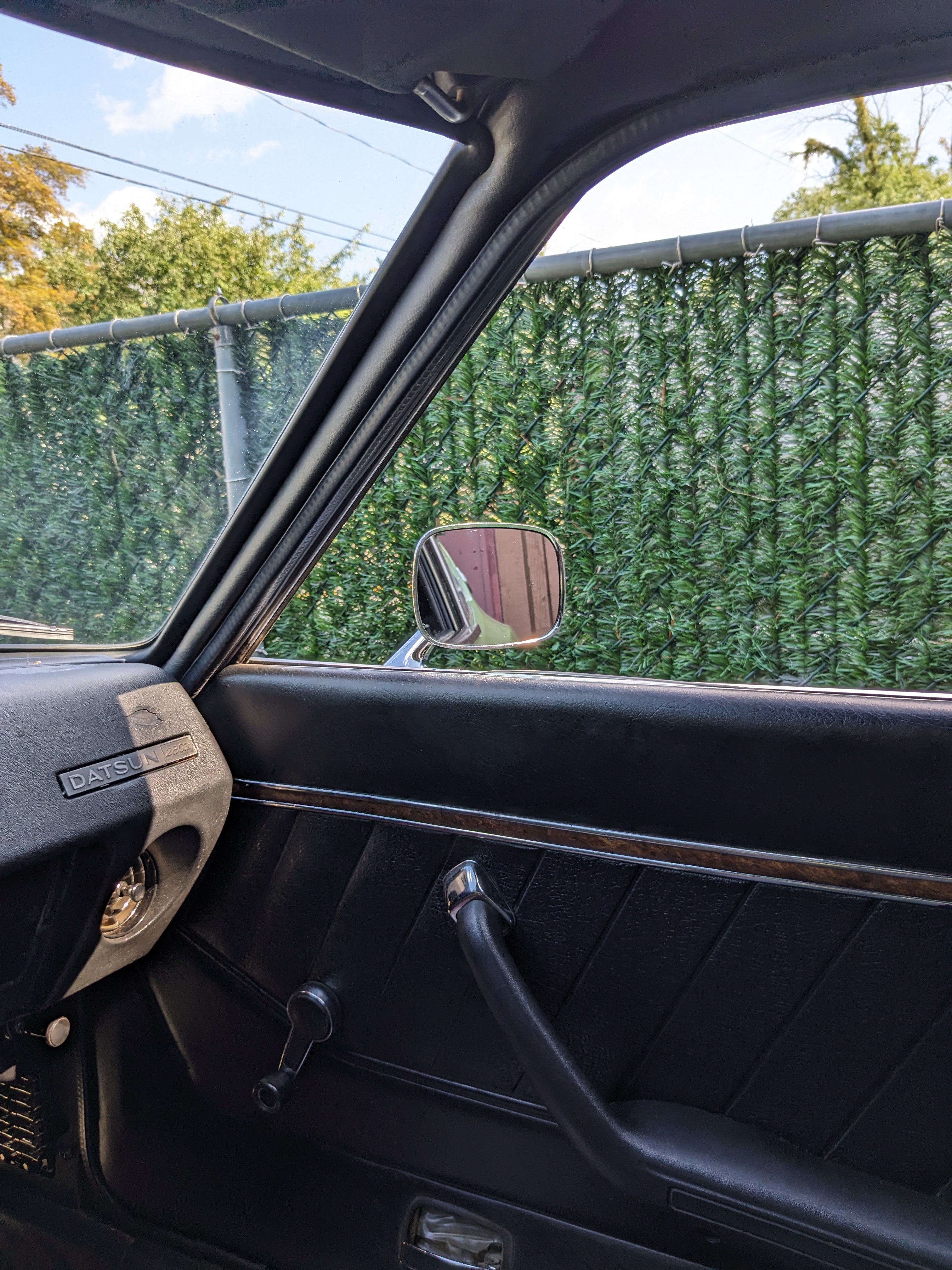
Installed the passenger mirror today Installed M5 rivnuts after this mount plate installed, M5 machine screws Much better!