HusseinHolland
Community Member
-
Joined
-
Last visited
Everything posted by HusseinHolland
-
Thanks for the input, CO. Yes, timing only fluctuated in conjunction with rpm. Yes, either ignition module/setup I don't see it being related to the BCDD block off, that only caused a high base idle condition, there's nothing in there that could be flapping around. The CIS system is fully operational - the easy test is to crimp off the feed hose from the low vacuum external side of the tb, and that will negate the IACV, dropping the idle to whatever base value is set at the butterfly & idle compensation (bleed) screw. As soon as the hose is released, if the system is functional, the IACV will surge the idle to around 1200, then settle at the controlled value of approx 850. Turning on the AC raises the idle about 100 rpm, so I'd have to say it's fully operational. I did all the mods without the dash in place (so no wiring to EMS, etc), so I did not run the engine after each set of mods as I would normally do to function test the work. So, fuel rail hoses, HEI mod, CIS additions, were all done without post-testing each individually. Basically, Murphy's Law has struck me for not following my usual protocol 🤪 I've almost got the dash/console back together, so once that's complete (mostly need to wire the WBO2 controller, so I don't contaminate the LSU9 WBO2 sensor) I will run it again & see what's up. The reason I'm leaning to a restriction is in part due to the fact there were hose particles evident when I removed the lines, and currently the system pressure does not drop off within the usual time frame (typically within a hour), it holds pressure for HOURS. I'm just going over the things I fiddled with to double check my work.
-
Apologies first of all for cluttering your thread with my problems! I'm still going to remove the rail & flush it. I have had situations where regulated pressure indicated was in range, but volume under demand was not. I'll have to see if I can record line pressure somehow on this system. Sorry for the confusion with the coils & ballast. I am NOT using the ballast with the HEI setup, that was when I switched back to the stock setup to test. The coil is relatively new (old stock), however I did try a couple others I have, no change The 125A breaker is on the starter feed, so the current draw with dwell/timing out must be very high. I can switch it out for a higher rating, but that won't resolve the cause. I've left this alone for now so I can get the interior /dash reassembled. I've also installed the WBO2 for the AEM controller, so I can see what the AFR's are doing when the symptom manifests.
-
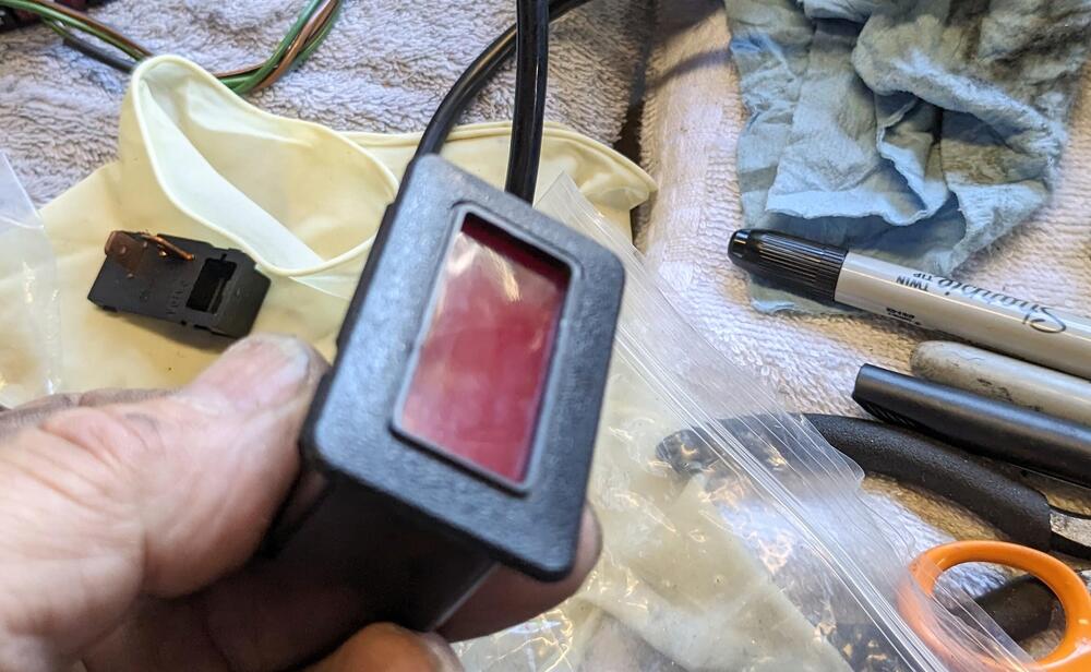
wired my relay feed to the L terminal via a new charge indicator bulb. Circuit works exactly as @SteveJ described. repurposed rear defogger lamp for charge indicator Bulb holder w/spade terminals

-
The point of getting the car running right now, was so I could vacuum & charge the AC system, to make sure there are no leaks - so I can put the dash back together & reassemble the interior... I found that one crimp I had made was insufficient. The high side line fitting to the orifice tube leaked with the system under pressure. I re-crimped it, and was able to then fully charge the system. Pressures seem OK for an 80º afternoon, and it blows cold. Condenser fan doesn't come on until high side hits about 250, but then drops pretty quickly. Anyway, I now know the AC system is functional. blurry pic of recrimp. Fortunately it was a fitting I could access & didn't have to remove the hose to do the job.
-
When I tested it with a timing light & held the rpm steady at 2500-3K, the timing would surge slightly in time with rpm drop, but that would seem pretty normal, no? If there is a flow restriction in the feed side of the rail, that would also do it. I've seen cases where a 'flap' of debris moves & chokes flow under high demand. I'm only thinking of this now because when I pulled the feed hose, there were particles(old hose breaking down, perhaps) in the inlet to the metal feed tube. I'll put a noid light on it, to see if the EMS is dropping out , does also seem plausible. Trying to go over systems I have specifically altered in some way that could be the cause.
-
That is correct. Since it's not due to the HEI module conversion, the only other obvious thing I had worked on was replacing the fuel lines at the rail. It seems plausible that there is debris in the line(s) that chokes the flow under higher demand. Regulated fuel pressure is good, but that doesn't mean the volume is there. Can't think of anything else I have done that could cause the issue at this point.
-
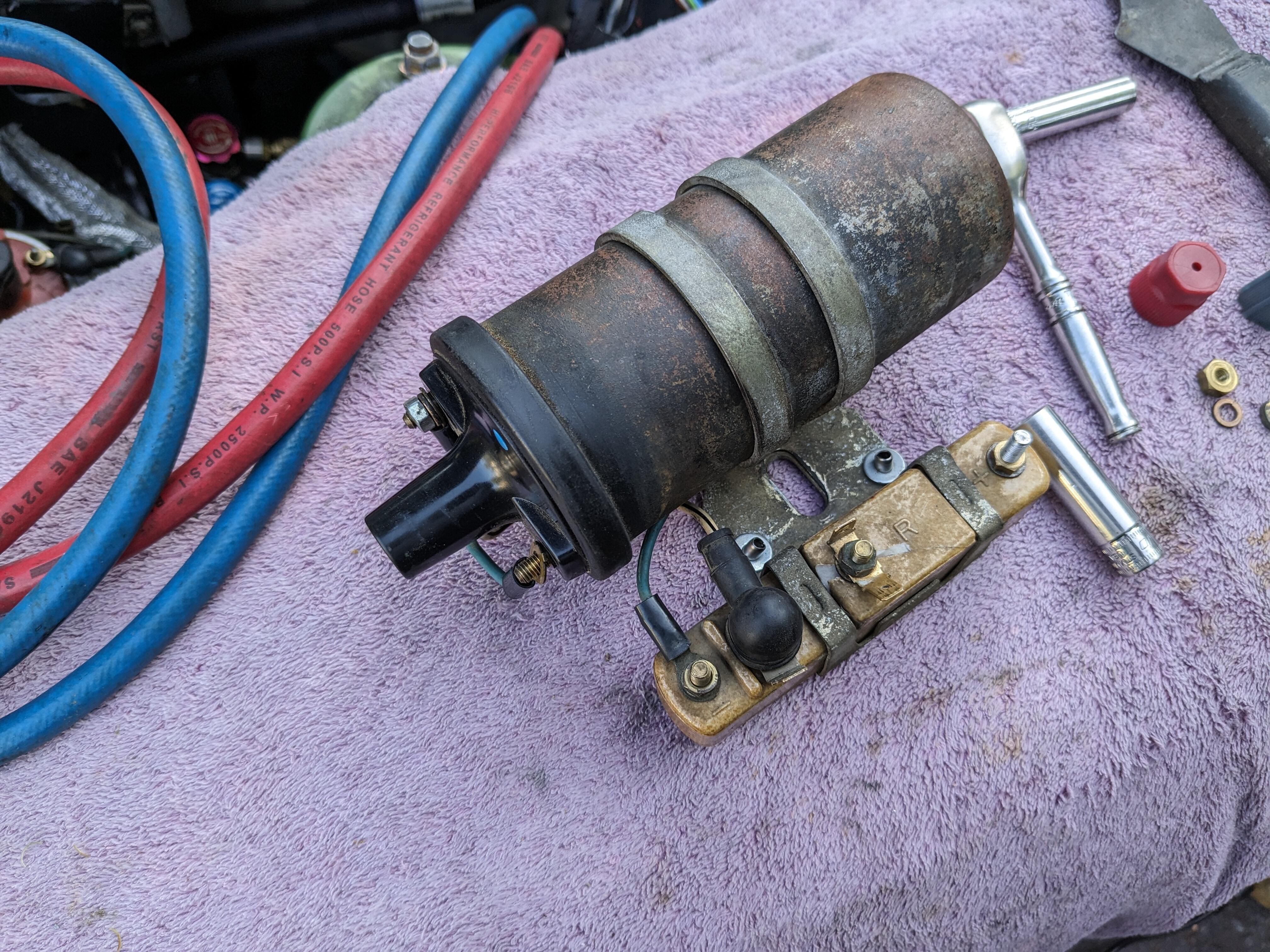
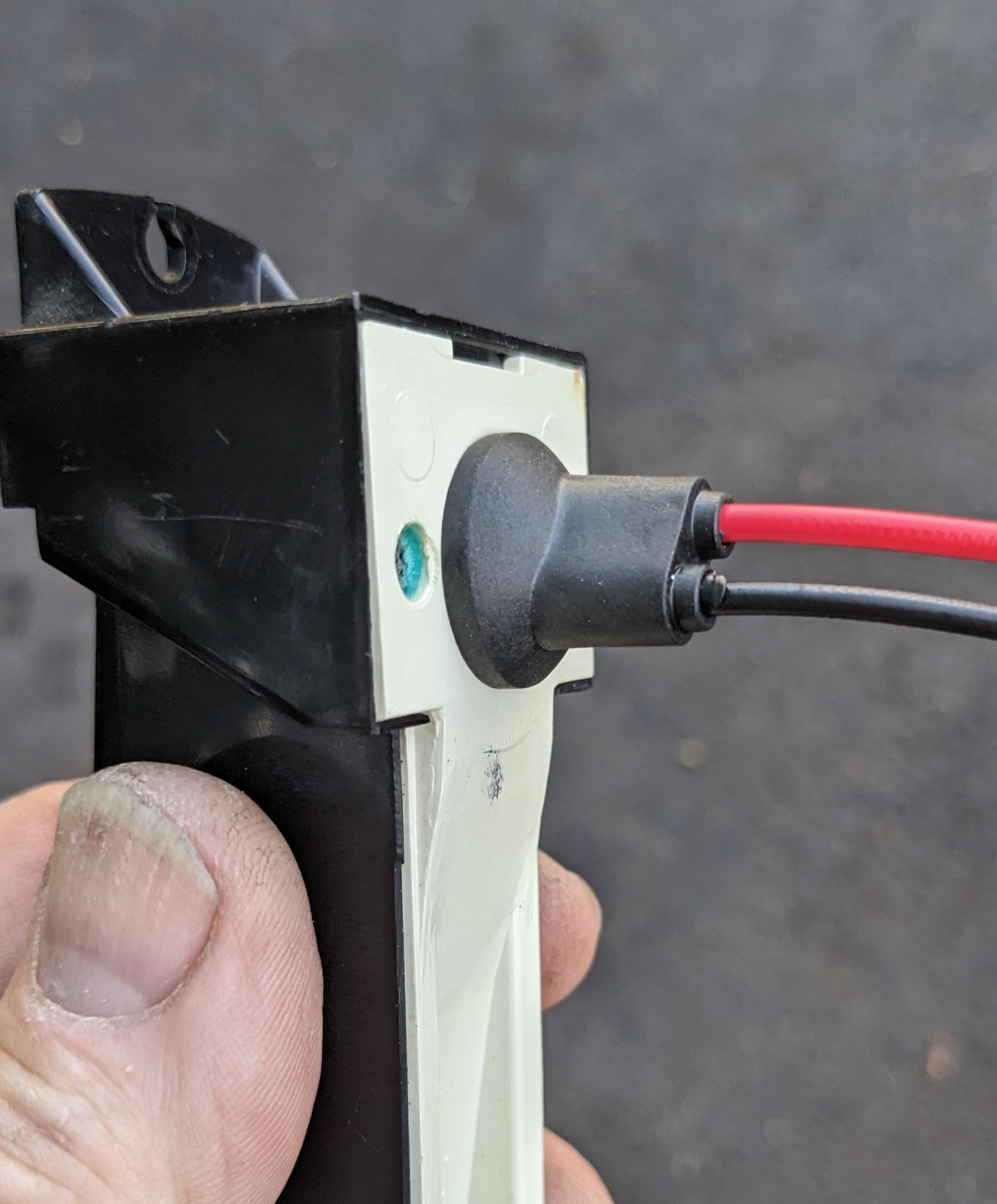
So the issue with the ballast was that without the center post, there is no continuity. repaired, then reassembled in outer casing Started right up....but.... still hunts 2500-3000K rpm with stock module setup. So, moving on from ignition as the cause, most likely at this point would seem to actually be hunting due to lack of fuel volume - possibly crud in the fuel rail, since I did have all that apart to change the hoses. YT vid of symptom


-
I put the rollers & brackets (from ZcarDepot) in some time ago - forgot to update. As far as the fitting moldings go, Silvermine has been useless. His sugeestion is to gorilla glue the molding to the the door, after you (somehow) bend them to fit the compound curve of the door without damaging them. I will never buy from him again, that's for sure.

-
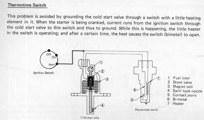
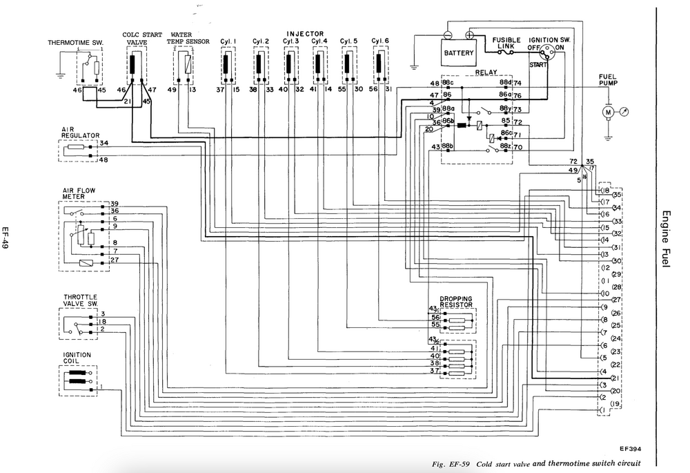
Would have been nice if the CSV had been ECU governed. Volvo didn't get that until the adoption of Bosch LH-2.2 in the early 80's, but they never used earlier L-Jet air-flap meter configurations . They used D-Jet and K-Jet before that, which also used the TTS like the Datsun.
-
I definitely had none of these particular concerns prior to messing with the ignition system. When cranking (with reluctor wires flipped), it felt like a motor that is way out of time, so perhaps that was causing the excessive drain. As it stands, with stock parts (and no increased voltage to ballast when cranking) within a short crank time, the voltage at the ballast is dropping to around 9v, according to my voltmeter.In any event, it won't start as is. So, I think I'll remove the ballast to see if I can fix it, and swap back the HEI connection & later coil, as at least I can run the engine at idle speeds that way & check the CSV operation again.
-
So I have discovered. It appears the only point to the #21 connection is to allow circuit continuity check, per the FSM. I tested my TTS today, and I have ground between 46 & the t/stat housing with a cold (uncranked) motor.
-
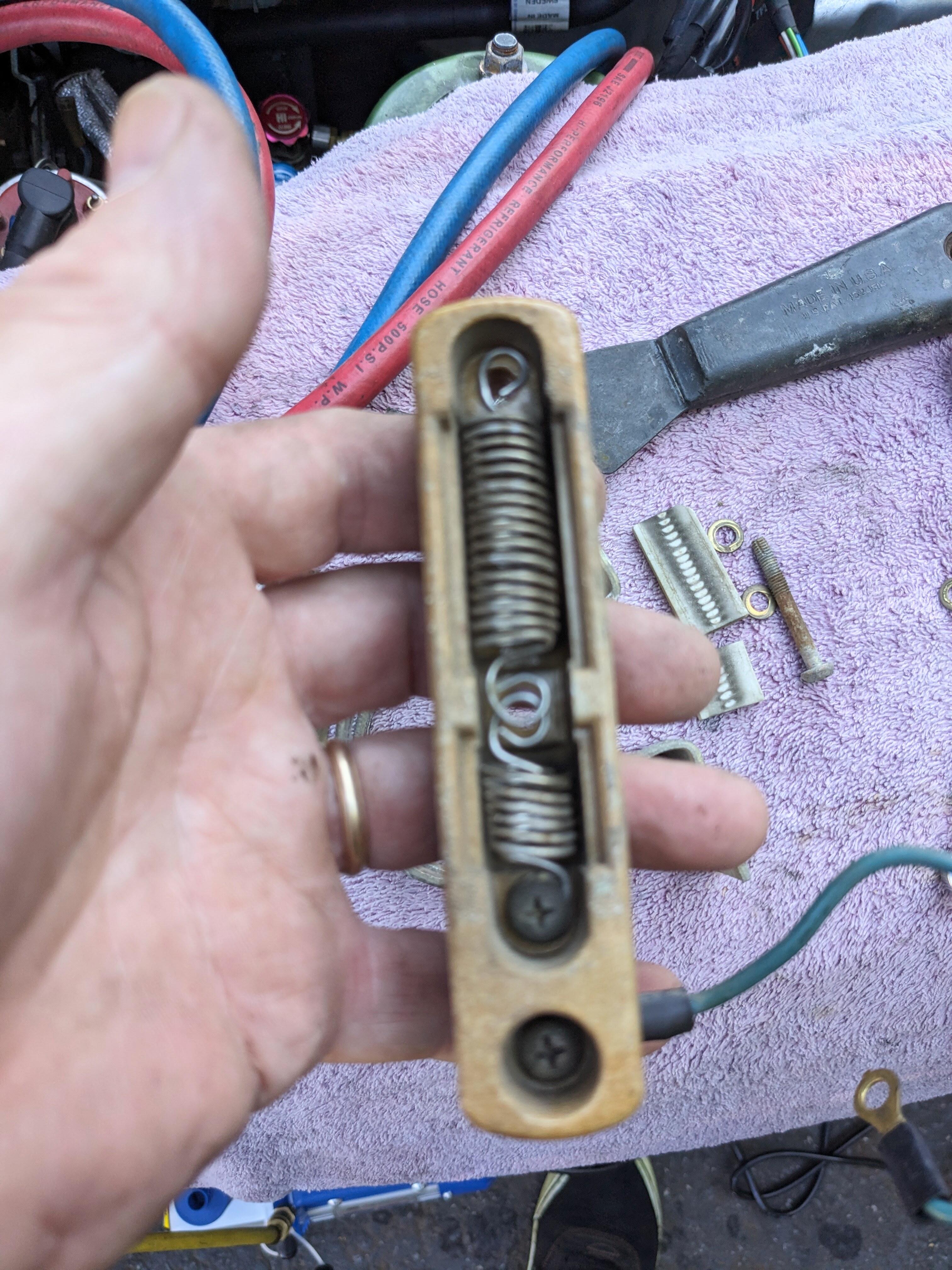
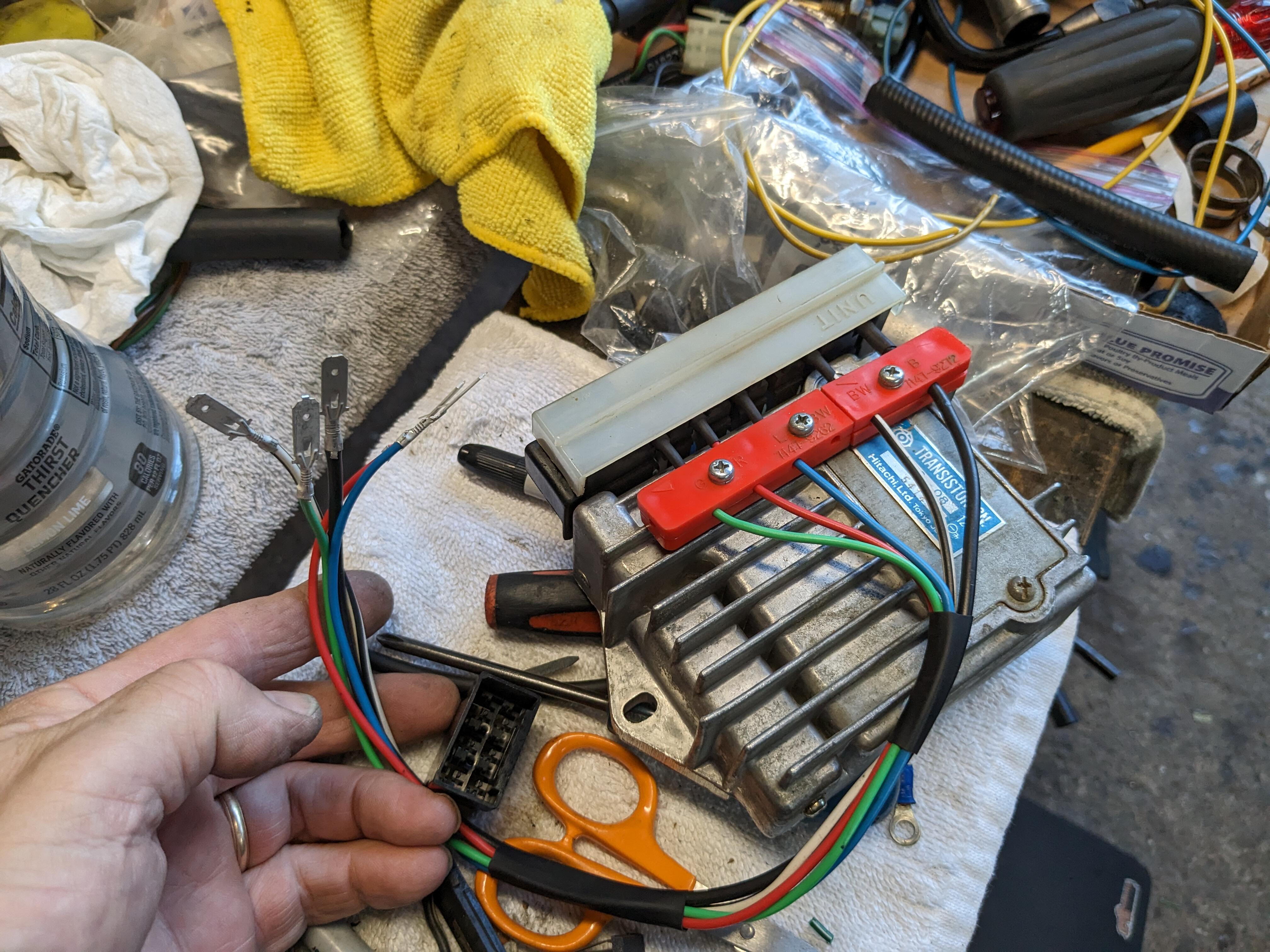
Swapped the coil & transistor module back in, however the middle post on the ballast snapped off when I did the conversion. Without that increased voltage when cranking, the engine is not starting. I'll have to see if I can get inside the ballast to add the intermediate post back tomorrow. In the meantime, I think I have to assume the SMP HEI module I bought is defective, the wiring is definitely correct. I've ordered a genuine AC Delco D1906 module to replace it.
-
A Fiat forum member pointed out what I was missing, and is not including in the FSM circuit testing - the TTS grounds the CSV, so with the TTS circuit bridged to check continuity of the wiring, the CSV cannot fire. I'll have to check the resistance of the TTS when cold & make sure it's OK, then I can reconnect it to verify CSV operation. The operation is described in the manuals, I've read it many times - I just blew right by it, 'assuming' the ground was ECU controlled, not within the TTS
-
I ran the motor & used the timing light, leaned over & revved the motor. Timing advances as expected when revved, and sits at approx 8º BTDC at idle. The motor goes completely flat when revved & held at around 2500-3K. Fuel pressure does not falter, I have a line gauge after the filter. I tried reversing the wires from the reluctor, and that had very bad results. It cranked normally for a few revolutions, then turned over very slowly, then not at all. After that, it was completely dead. I thought the battery was drained - I found that cranking like that blew the 125 Amp fuse breaker on the starter cable from the battery. I replaced that, put the wires back & it started again normally. I don't understand why the ignition system is creating such an extreme current draw when the reluctor wires are switched. No one has previously mentioned any issues with reversing the reluctor wires. I tried another coil, in case that was an issue. I'm going to put the stock module and coil back in & confirm whether the issue is with the HEI conversion or not. re-wired to plug into the modded harness

-
The motor goes flat when revved, It is acting as described earlier in this thread. I'll put a timing light on it after work & see what's up. I'm going to reverse the reluctor wires first to see if that resolves it, since I can't rev the motor and watch the timing marker at the same time by myself. I have not touched the distributor other than to replace the cap & rotor.
-
Indeed - however the only recent change to the EMS I've made is the HEI module - 'hunt' may not be the ideal term, even though it kinda feels like it - the motor won't rev as described by others in this thread when the reluctor signal is reversed.
-
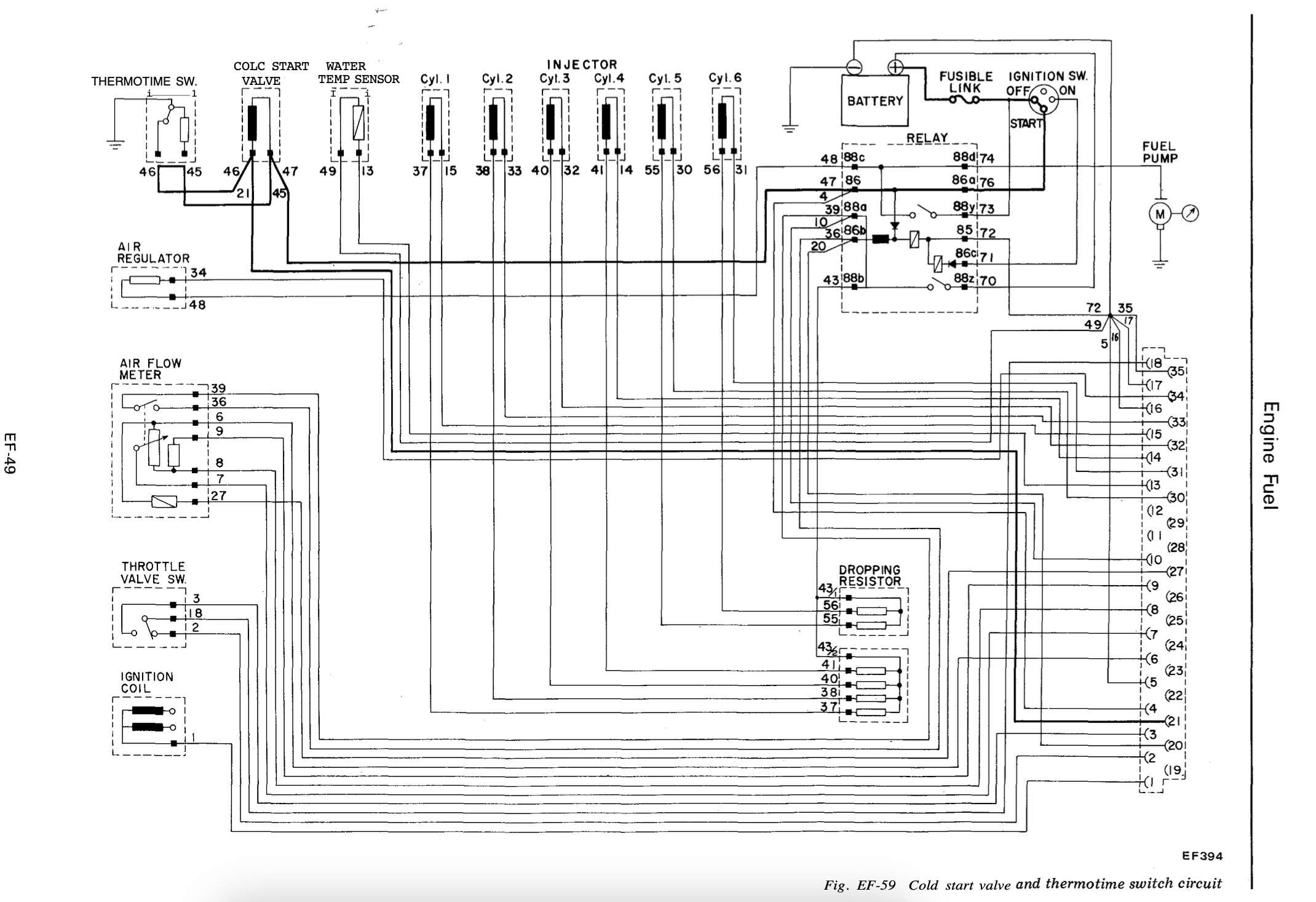
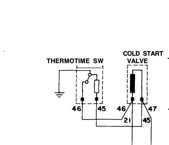
Still back & forth with the cold start circuit. I have continuity in the harness from 21 at the ECU to the CSV & TTS. The factory test is to disconnect the ECU connector & use a voltmeter on pin 21 - if there is battery voltage when cranking, the circuit has integrity. I did that, and got the desired result. However, the CSV does not fire, even though I know the valve is functional when wired independently of the circuit. What I'm having trouble with is the way it's all wired - looking at the diagram, it appears the TTS is in parallel, not series, so HTF it would interrupt the current to the CSV? Makes no sense to me. The reality of the circuit wiring is thus: FSM diagram crop Further investigation is required.
-
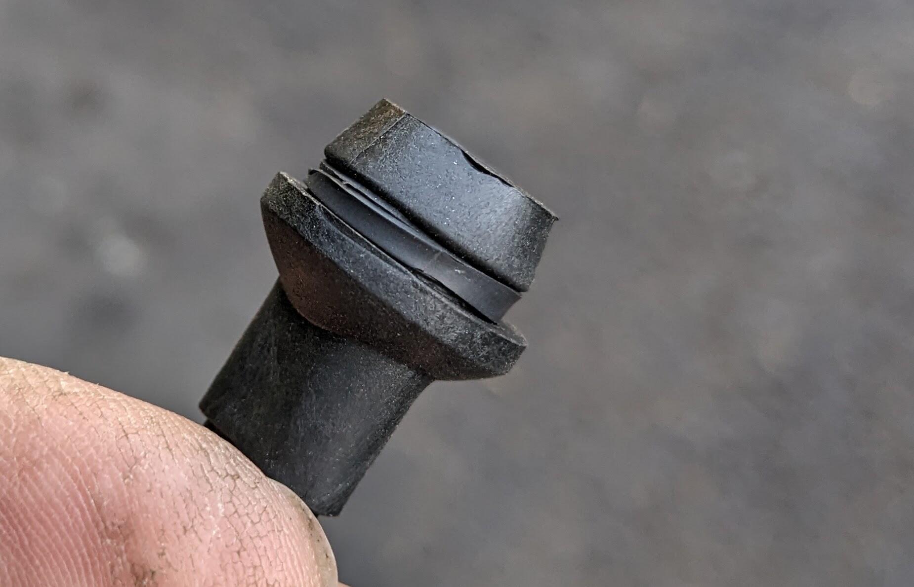
They are kinda loose in the hole - 16mm I think I measured the orifice at - so I added a thin strip of heat shrink to make it snug


-
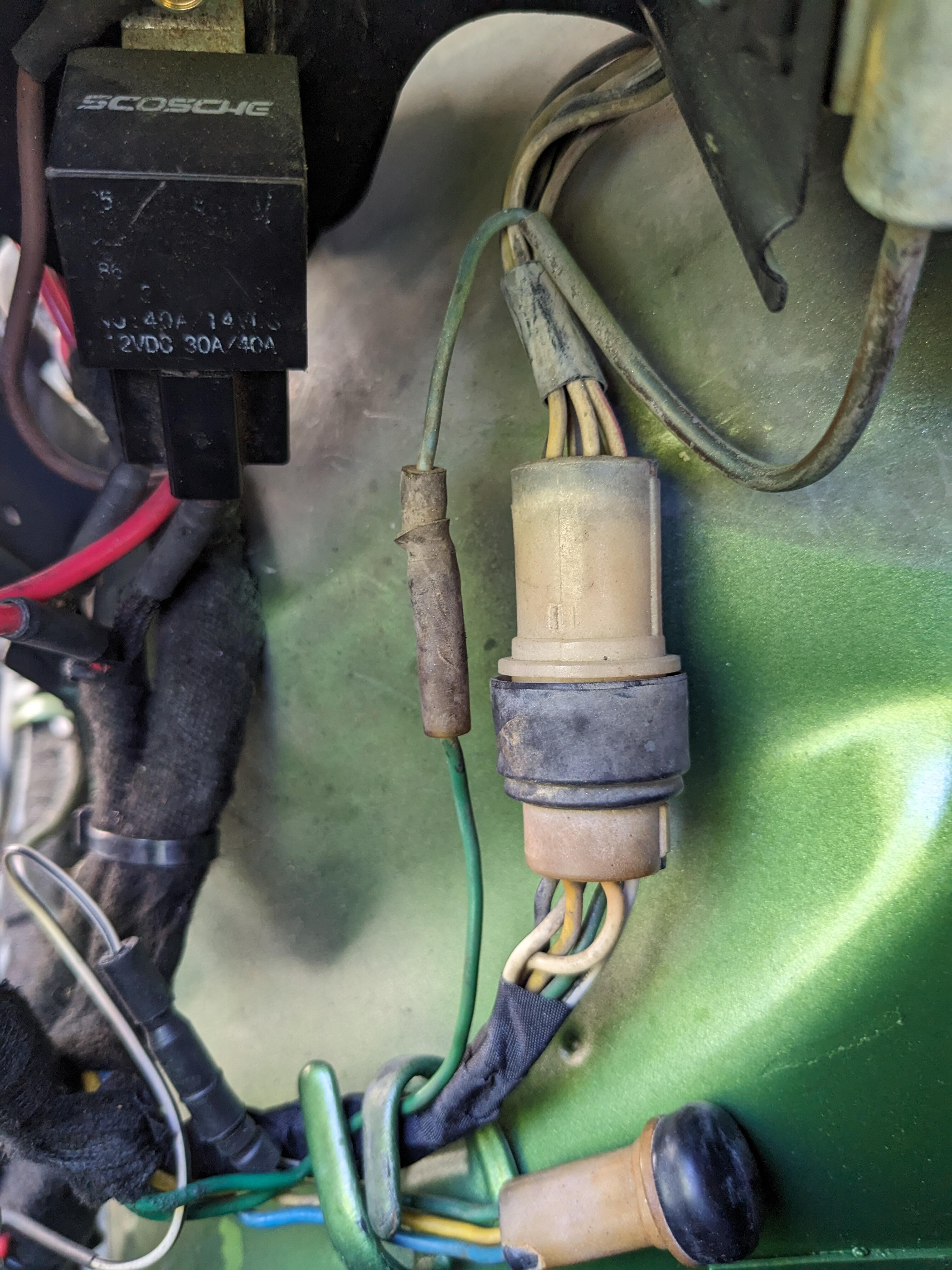
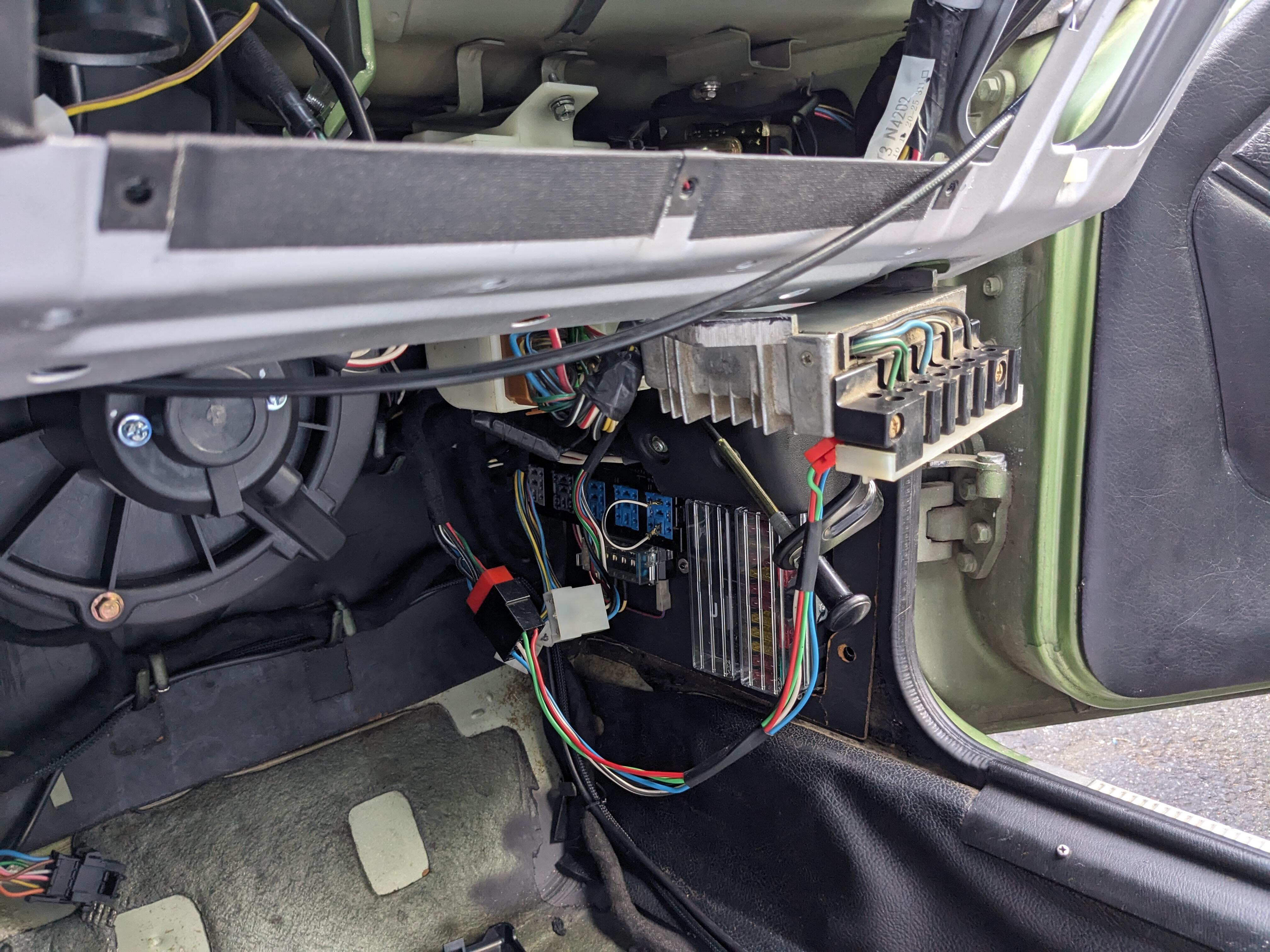
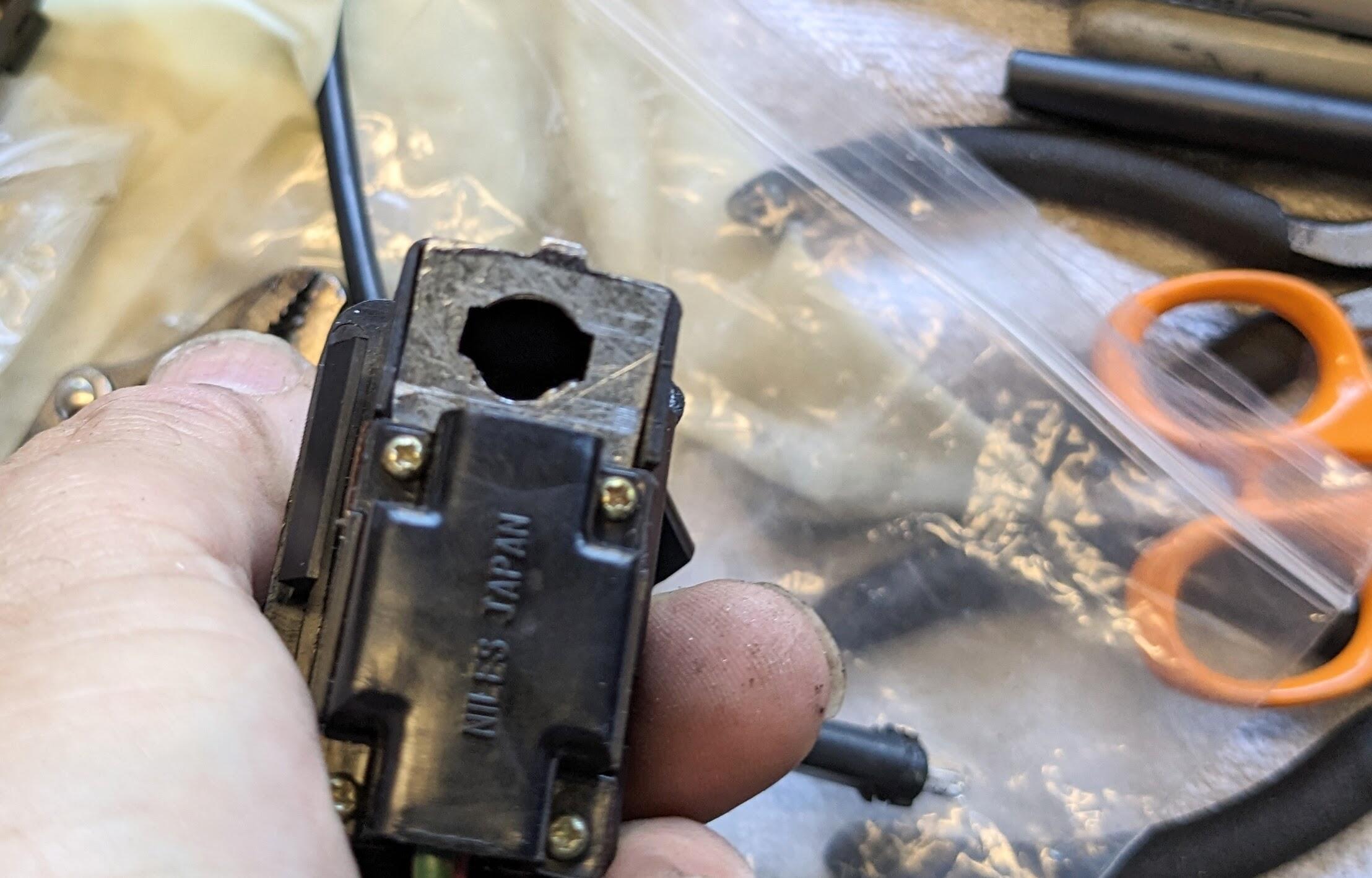
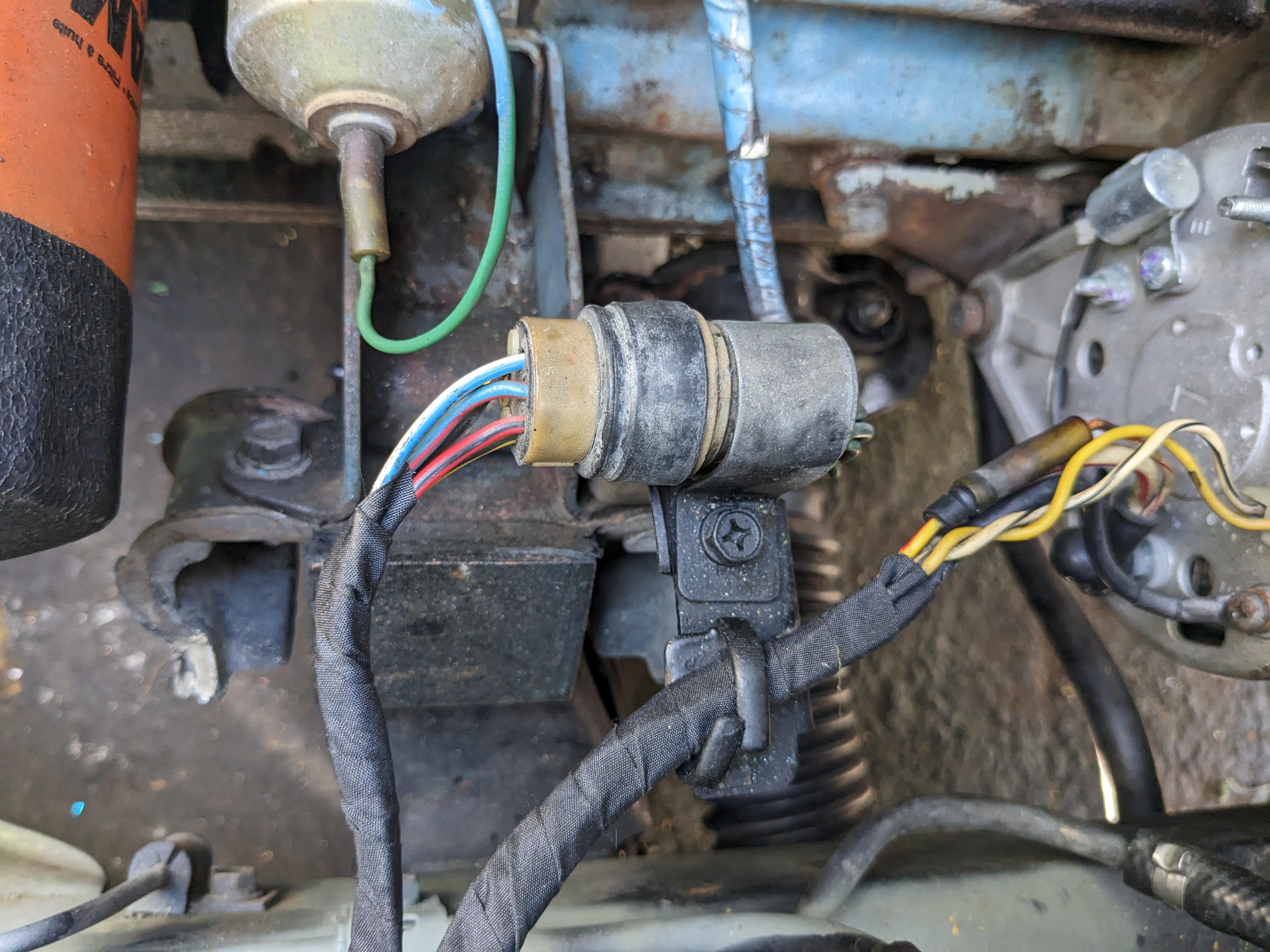
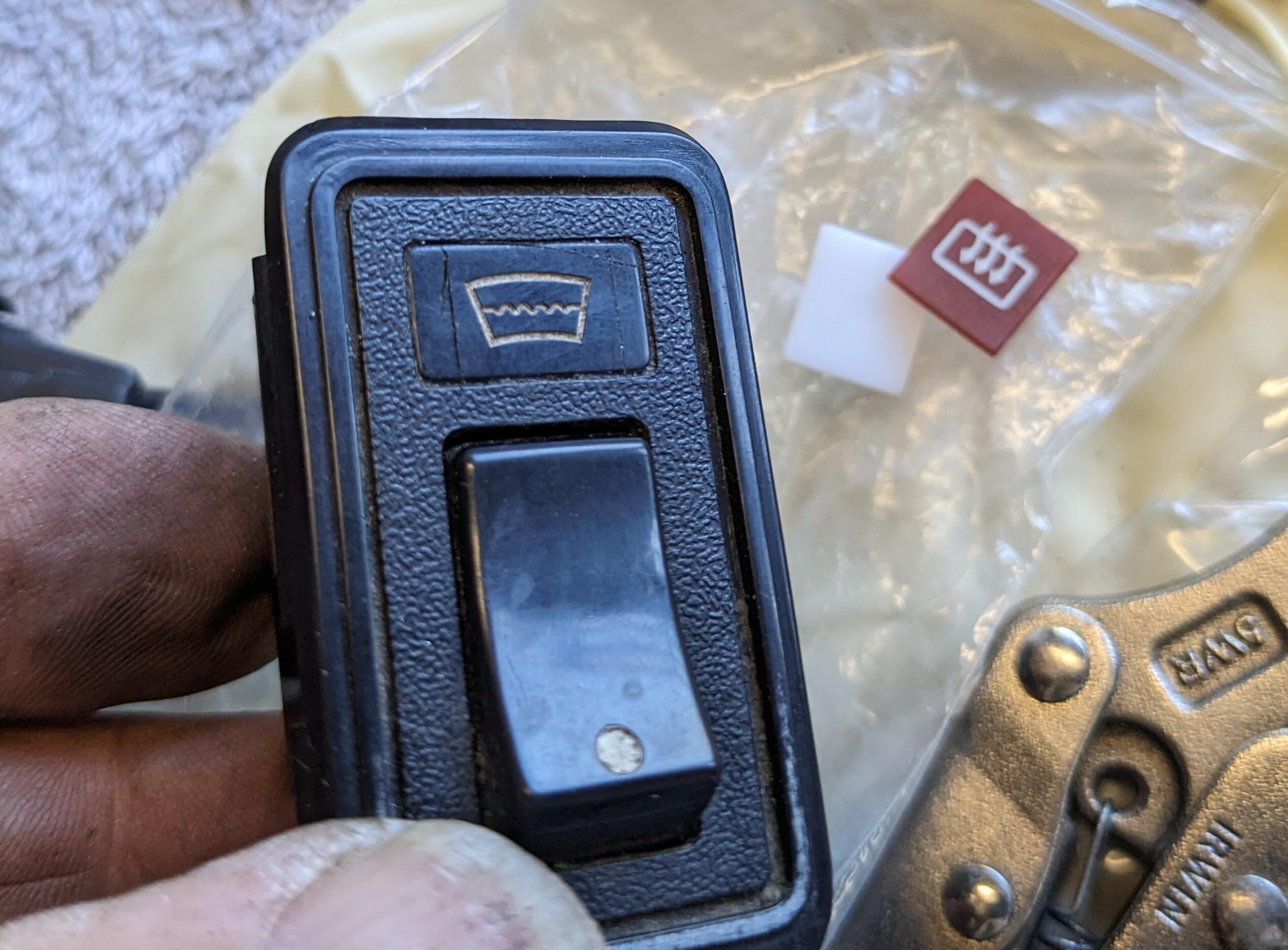
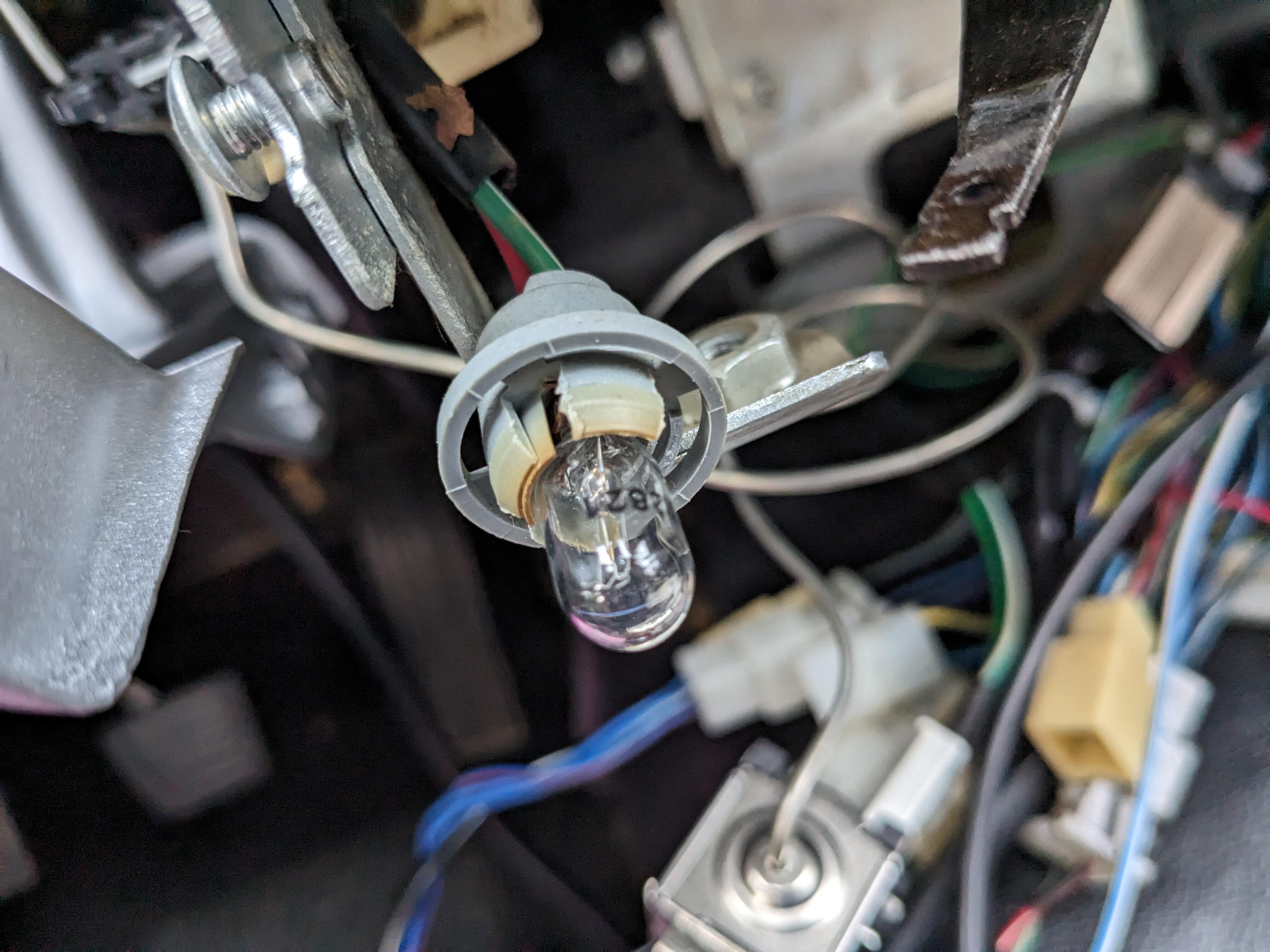
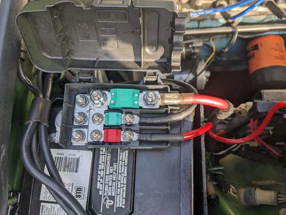
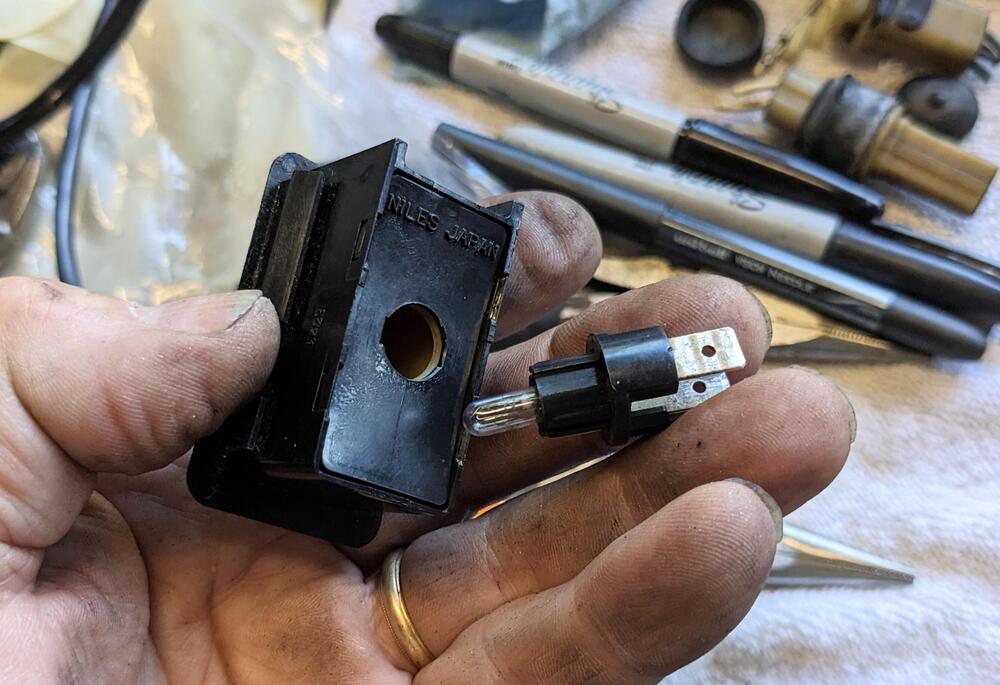
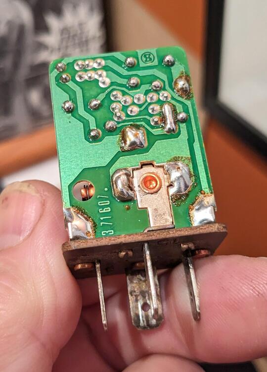
Did the AC relay signal re-wire using the L terminal and repurposed the low fuel lamp for the charge indicator lamp. Works as expected. V/reg connector, with wh-bl connected while I was in the bay I repurposed unused AC system wires and moved them to the engine harness connector for Oil temp sender (Bl-Wh) and to the alternator for Voltmeter (Y-R) I need a spot for the charge indicator lamp, so I removed the massive "Rear Defogger" lamp & fitted a red lens, then added a bulb socket plate to the rear defogger switch, similar to what the Hazard switch has. I had to cut a hole in the rear defogger & add a color plate w/icon for the defogger re-drilled the backside to accept a bulb socket w/spade terminals making the bulb plate marked area to be cut out build plate fitted illuminated Last thing, the 1363449 AC relay is dead - I re-flowed the solder joints, but it still doesn't switch after the 10sec delay, so I have ordered another


-
So today I ran the motor until it was warm , after checking the cold start circuit. I found that if I rev the motor to around 2k & hold it there, it hunts. Is this the condition others described that requires the reluctor wires to be reversed?
-
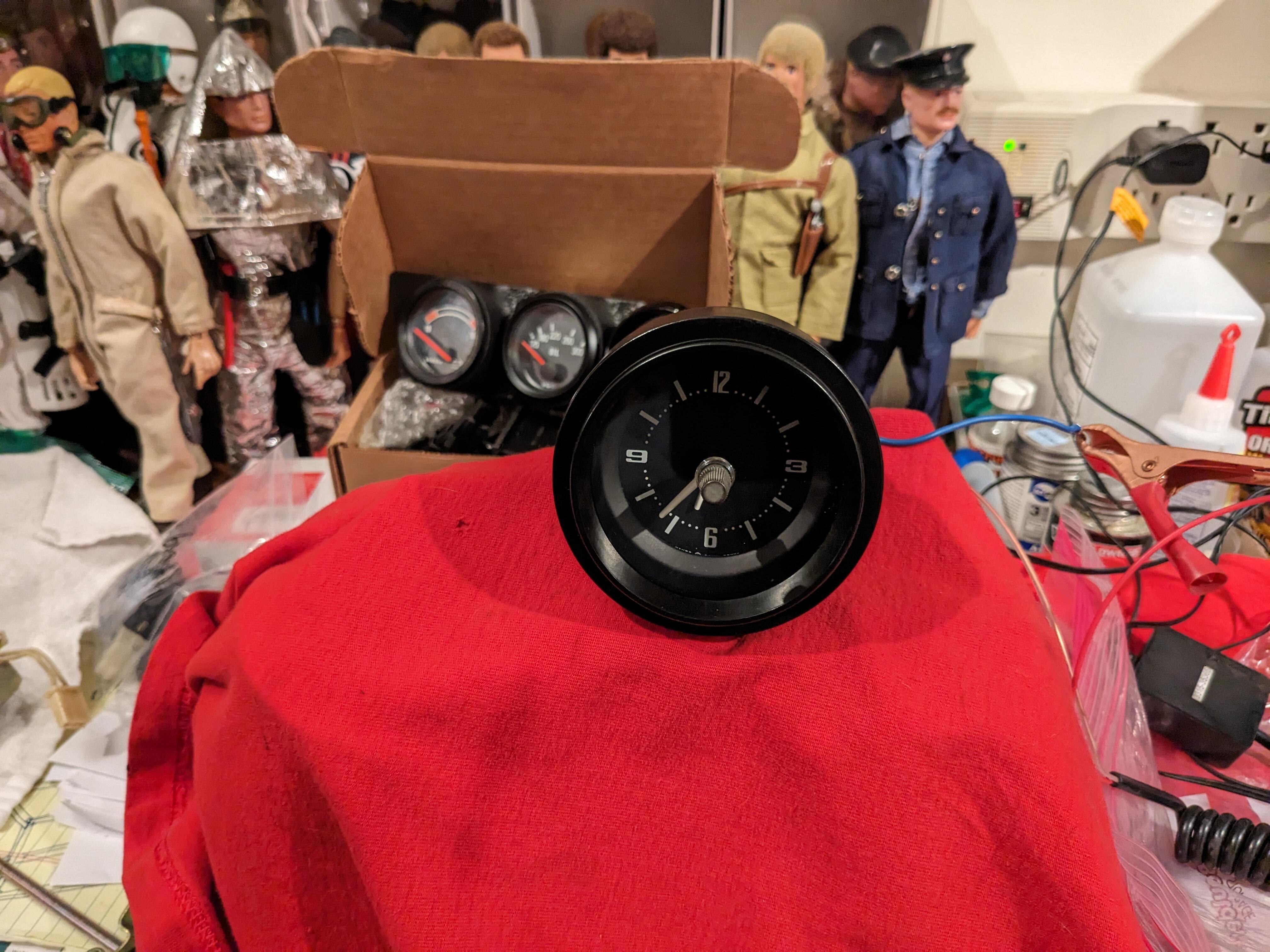
So, I have the clock sitting on a shelf running. It loses about 5min over 48 hours. There is an speed adjustment marked S & F. Question is, doesn't that mean rotate toward S to slow it down, and toward F to speed it up, or vice-versa?

-
Did you mean to post in the bulb socket thread? 🙂
-
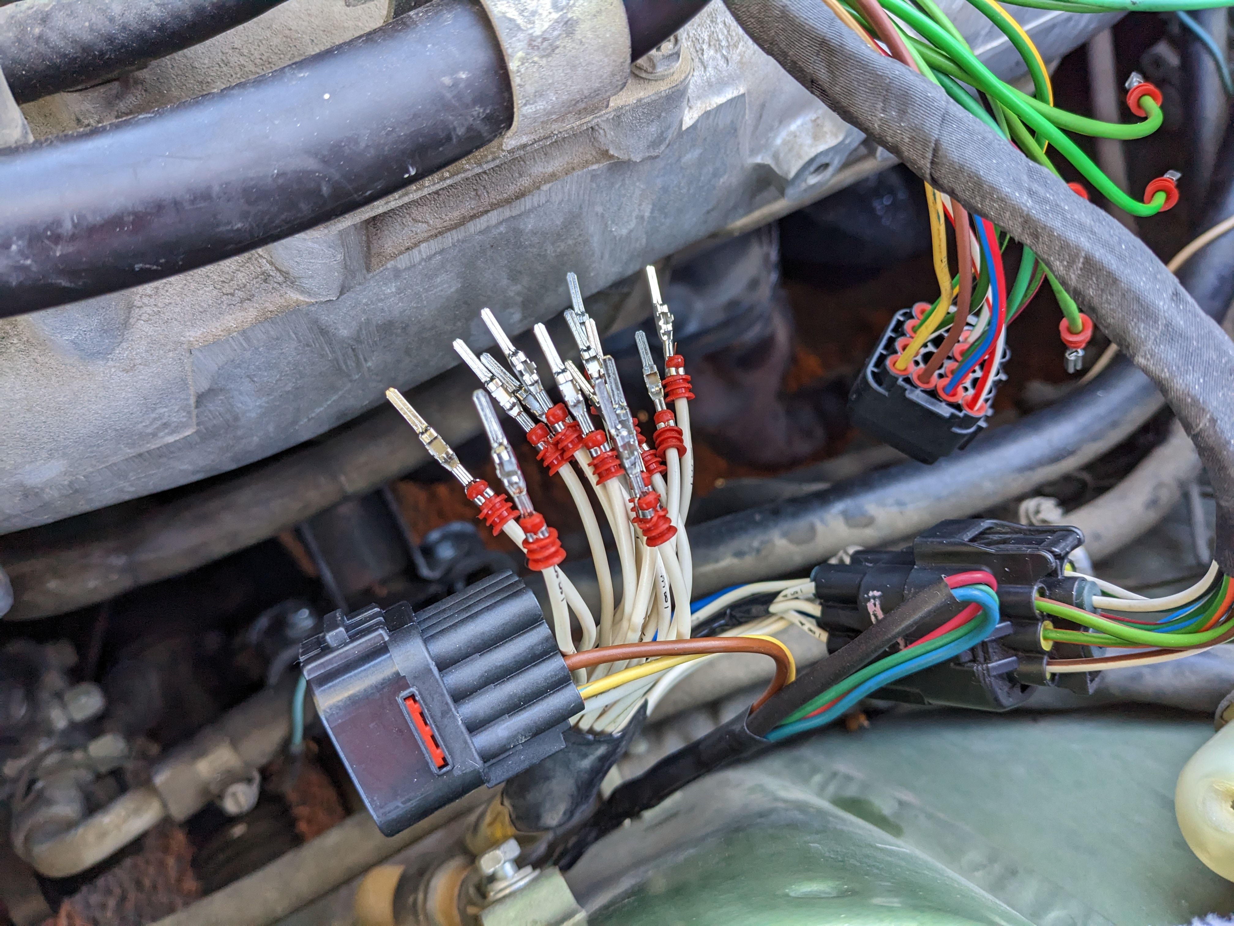
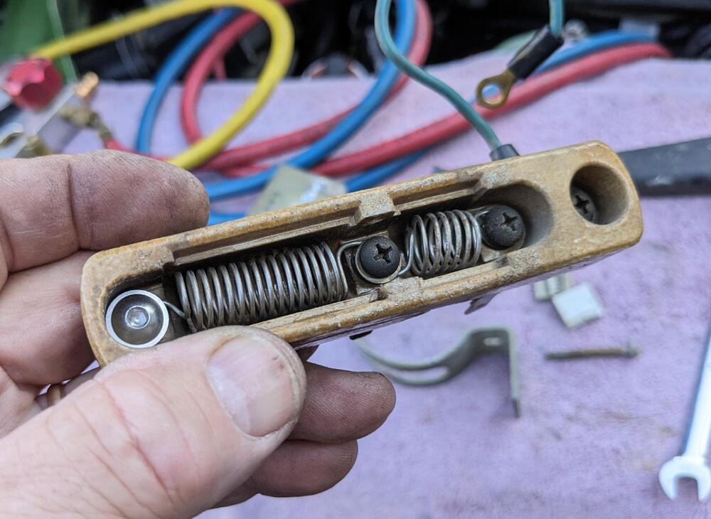
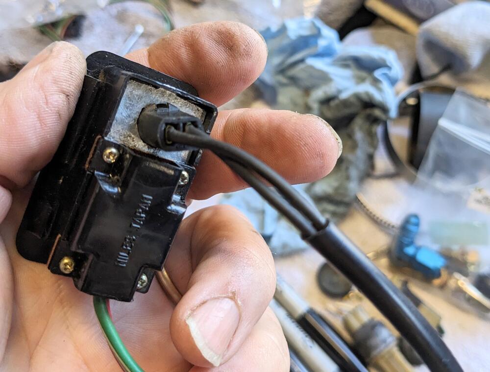
So, now that the ambient temps have dropped, I see that the cold start system is not actually operational. When I rewired the EFI harness I found the ECT & TTS were mis-wired. I don't know if that caused an issue at the ECU. In any event, I bridged the TTS connector, and have voltage output from the EFI relay 86 terminal to the cold start valve when cranking (checked with test lamp on pin 86 at relay, and 45 at CSV.) I confirmed the CSV functions by powering & grounding the CSV to the battery with the fuel system pressurized. The CSV does not inject fuel however, and if I put the test light across the pins of the connector, it does not light, which would indicate to me that the ground side of the circuit is non-functional. I tested the continuity of the harness from the TTS connector (pin 46) and the CSV connector (pin 46) and both have continuity back to the harness plug I made. Tomorrow I'll have to check the continuity of the ground side of the harness from there back to the ECU connector. My question is, does anyone have experience with this aspect of the system that would indicate a common failure point? The wiring diagram is not accurate in terms of the actual wiring of this circuit - the bridge circuit for the TTS in not at the CSV, is it back in the harness on the inner fender, where 47 is T'd off into to 45 wires, and 21 is T'd into 2 46 wires. I discovered that when I did the re-wiring.

-
Thank you Steve! I ordered those to see if they fit OK.
-
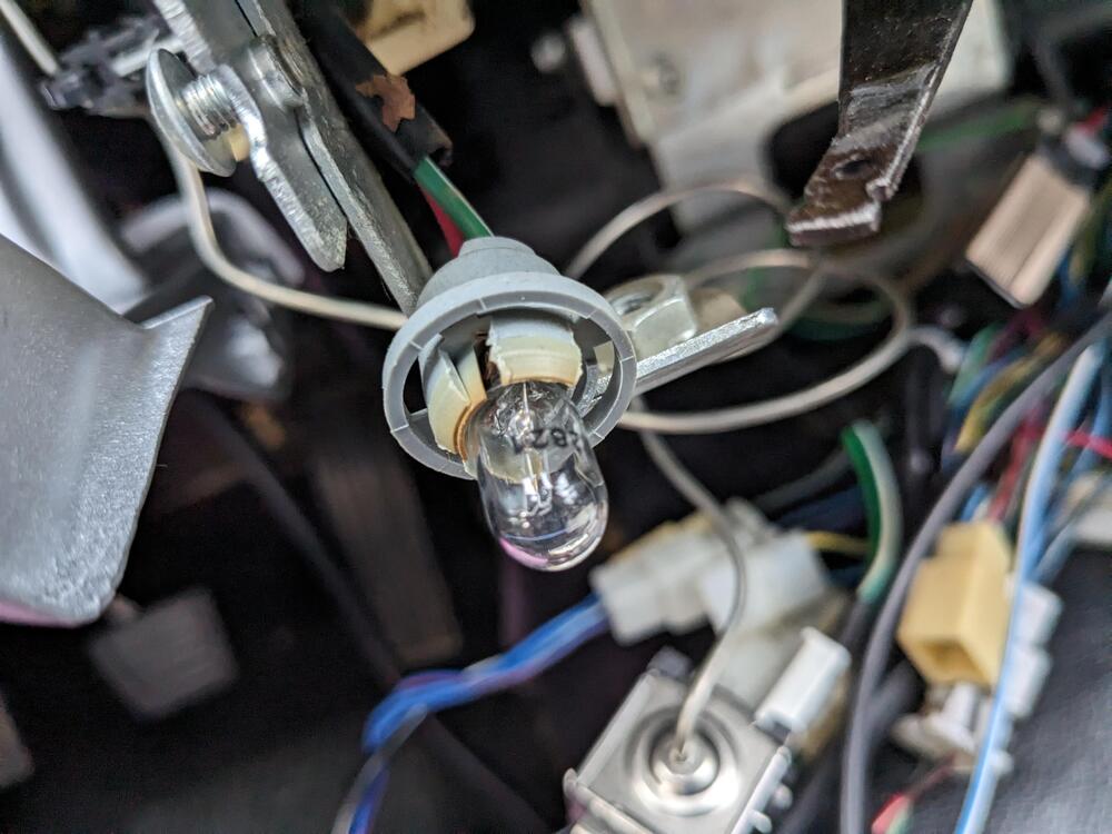
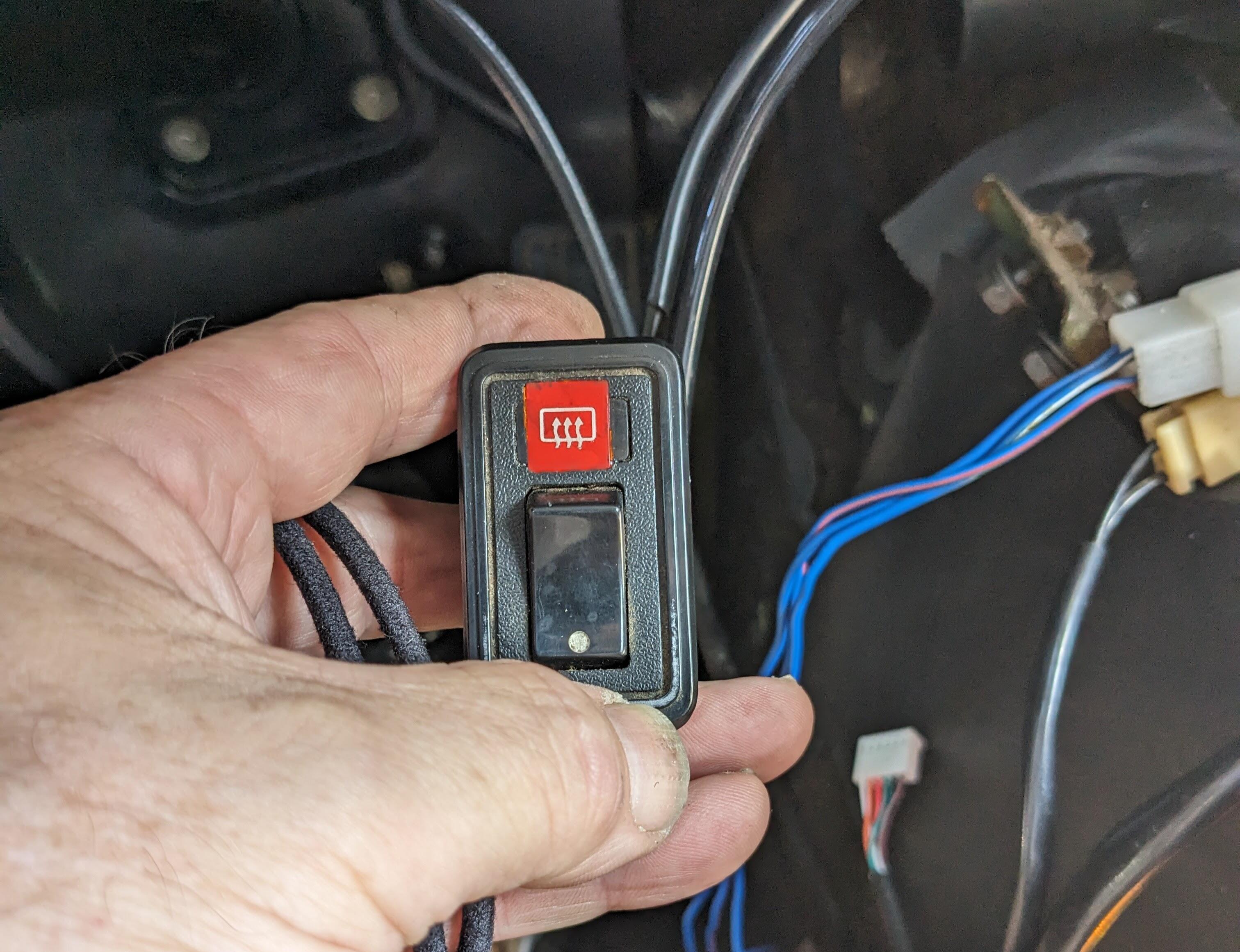
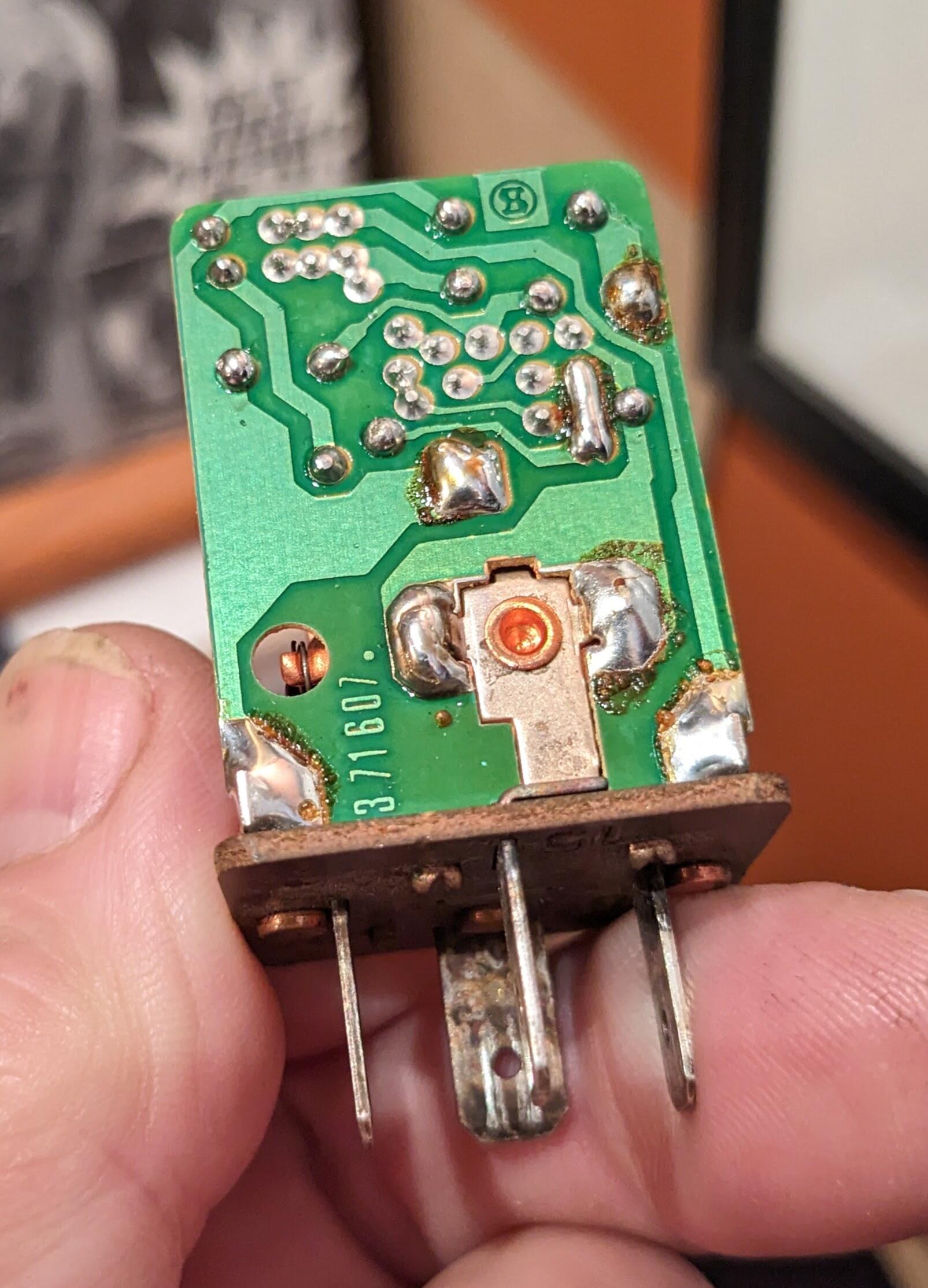
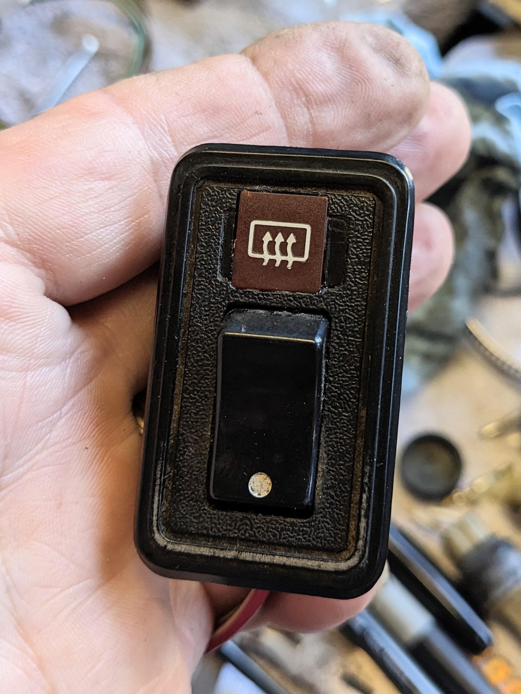
I have at least one socket with broken/dried out tabs for the HVC control panel - I'm not finding anything searching for repalcement sockets in general - has anyone found a generic / aftermarket bulb holder/ socket that will clip in place, that also has the correct bulb depth? I know the bulb socket for the low fuel light will fit here - so I will likely cut the harness on that & use it here. I'd still like to know if there are any useable options for the instrumentation.