HusseinHolland
Community Member
-
Joined
-
Last visited
Everything posted by HusseinHolland
-
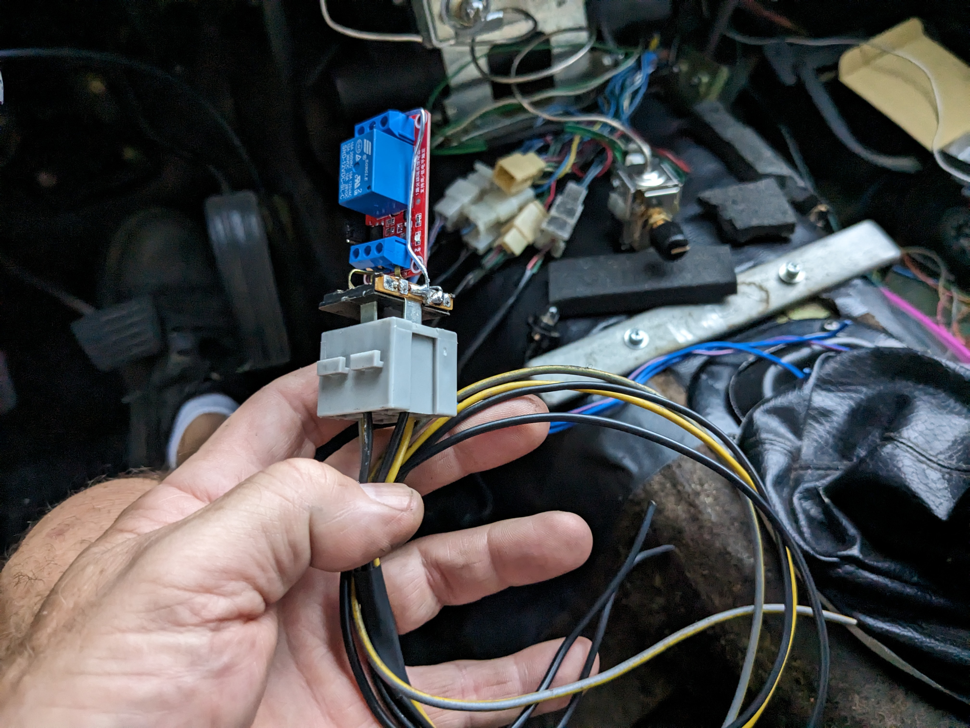
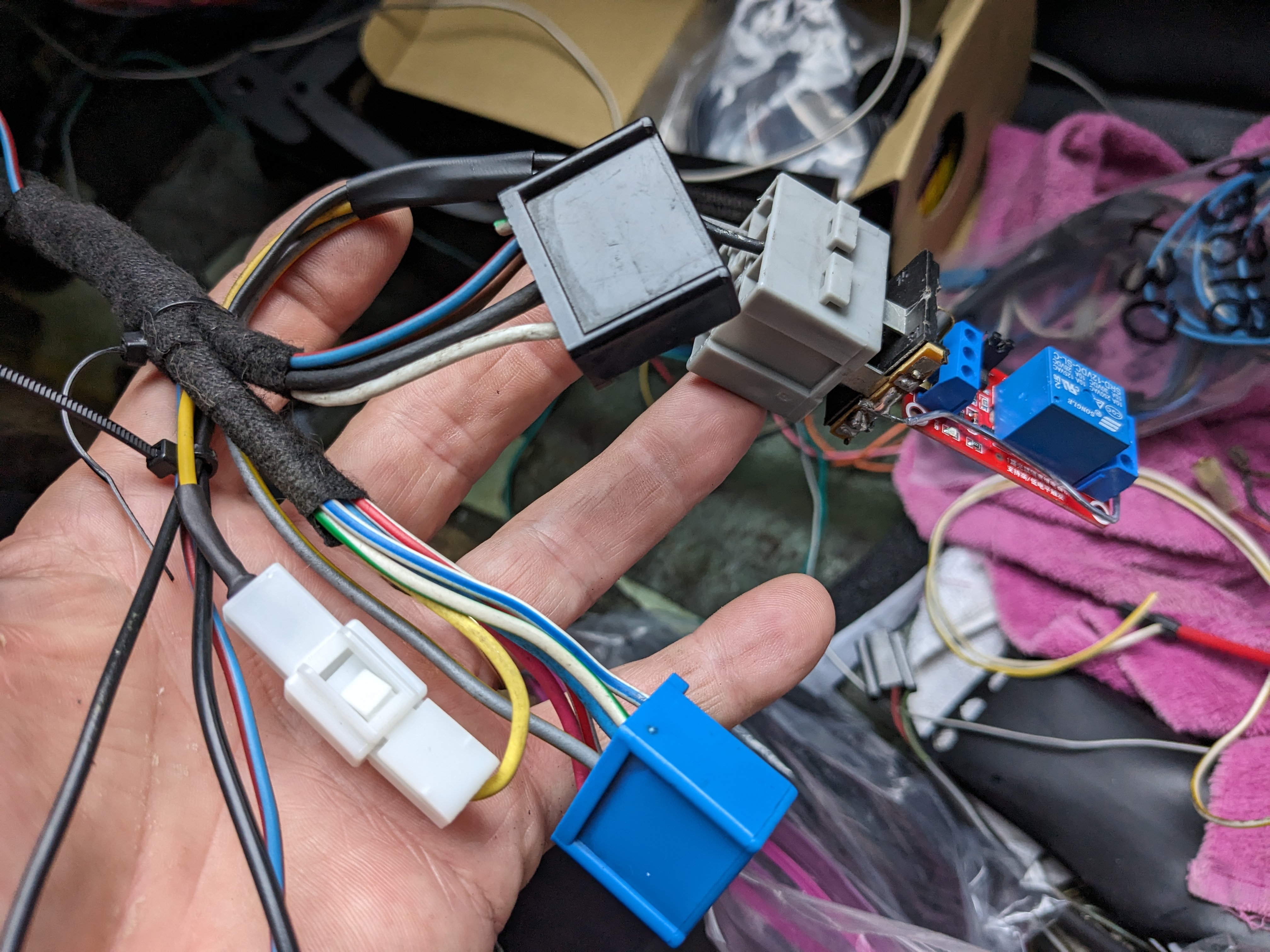
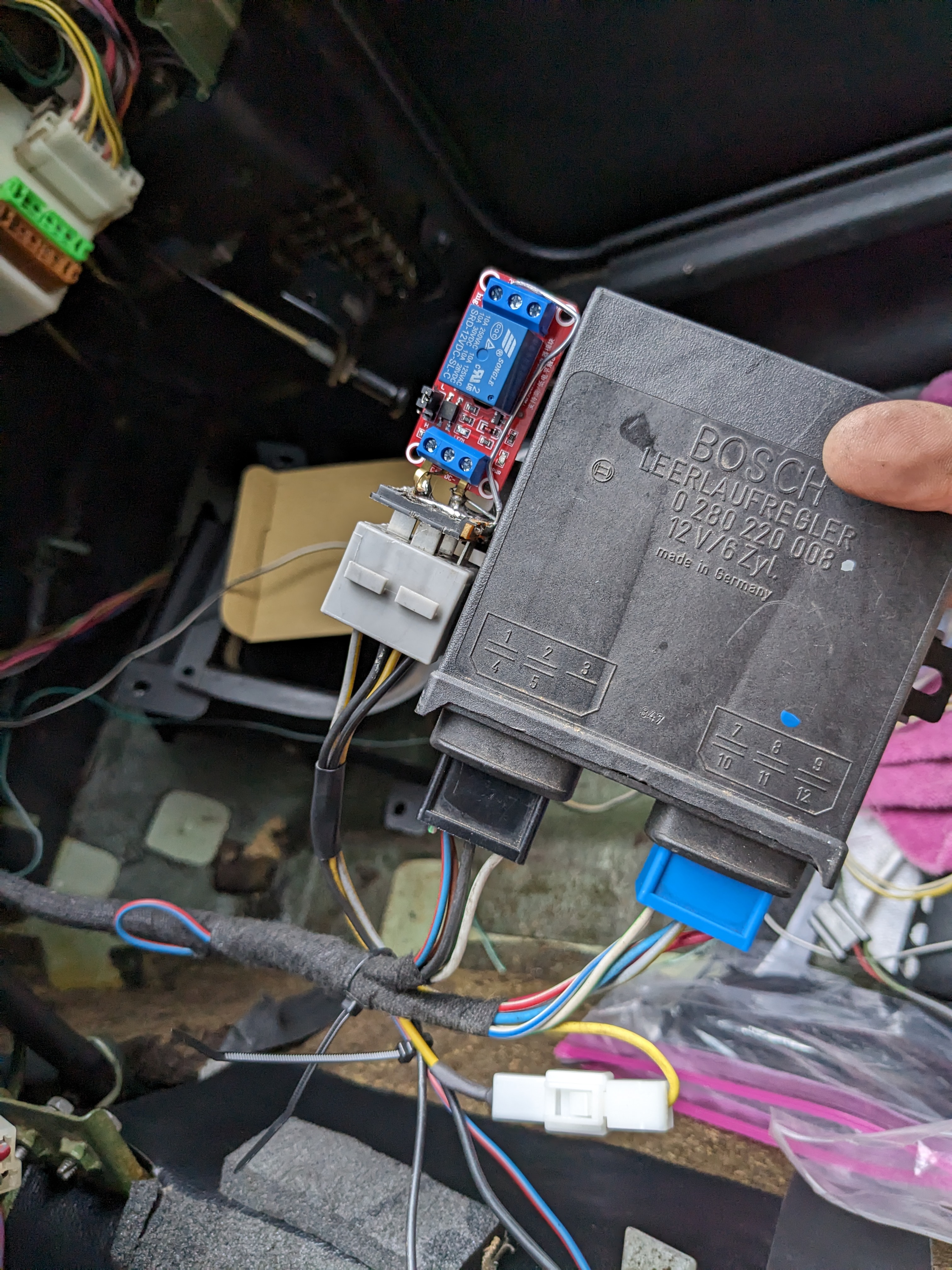
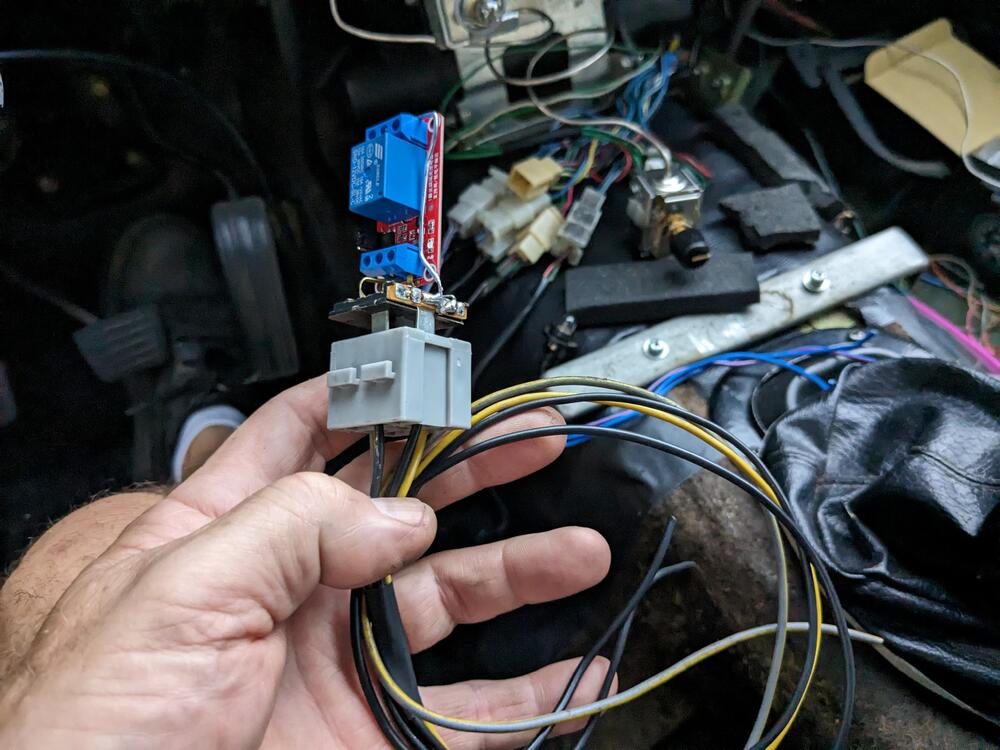
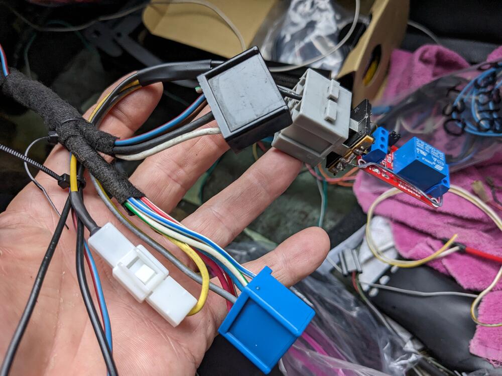
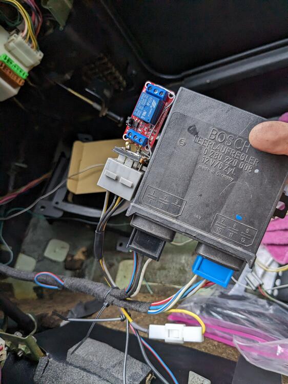
The thing is, the ECU for this is not readily available, and typically expensive if you can locate one. I'm doing it because I have the components, and my stock AAV is dead anyway. This will all only be used for a year or so, then I'm putting in a 350Z drivetrain 😁 Weather has been terrible here, so not getting much done. Did a little work on the wiring inside the cabin while it was raining harness for transistor relay for switching the stock TPS signal to the CIS module to open at idle, ground off idle. yellow wire is the signal from the TPS, so it needs to go to the relay first, then the switched leg goes back to the module it will be situated alongside the module. I will need to sleeve the relay
-
Doesn't that mean the voltage drop would be even greater? I assumed reducing the value of the resistor would be the goal, to increase the stimulus of the transistor on the coil?
-
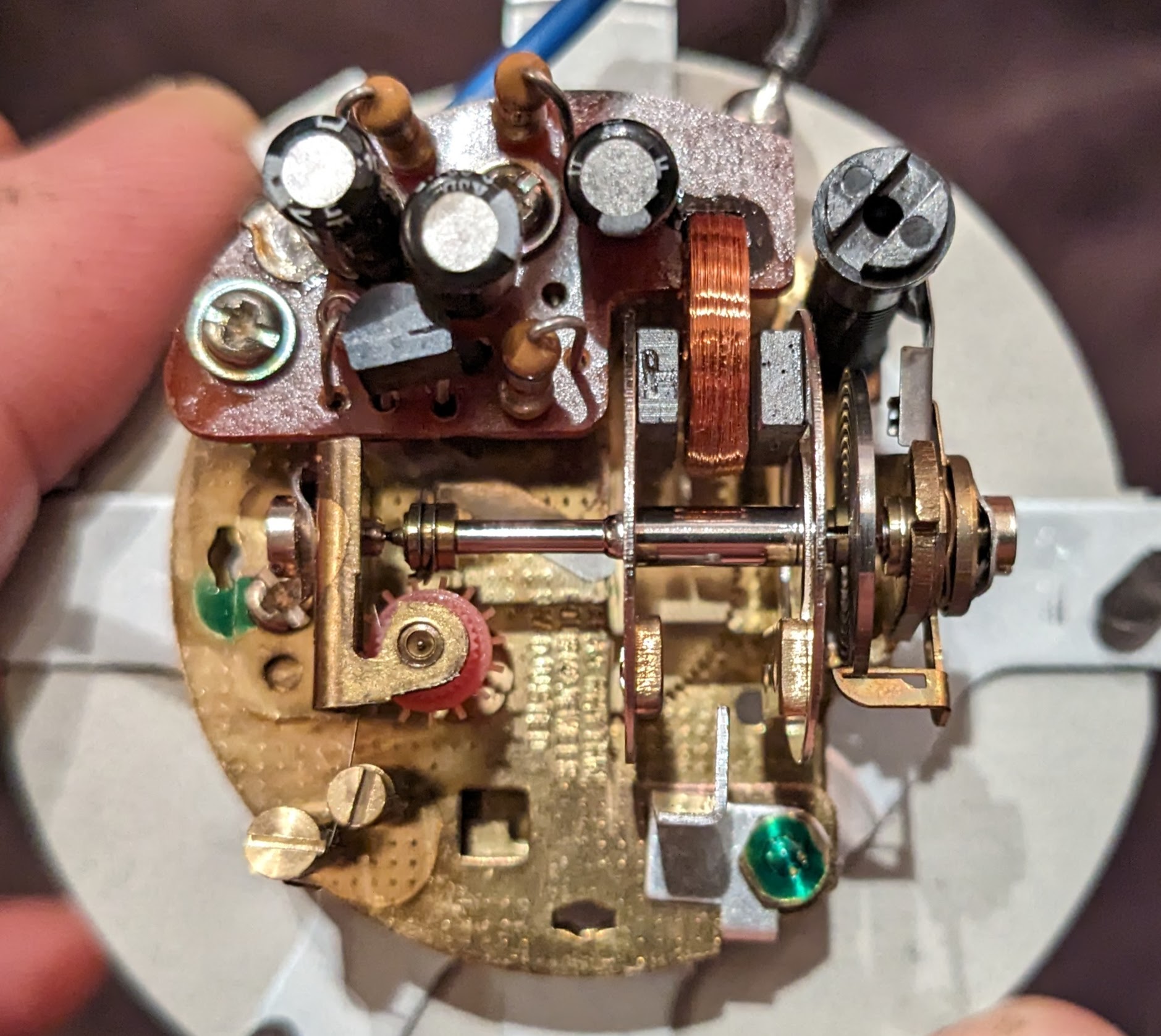
I did connect the clock directly to the car battery (inside the case), made no difference. The caps, I bought one of those sets that has a large range of values. I replaced all three - 2 x 10uf, 1 x .22uf. I presume all I can do play with the high value resistor, since I can't check the actual values of the caps.
-
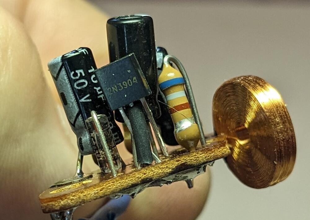
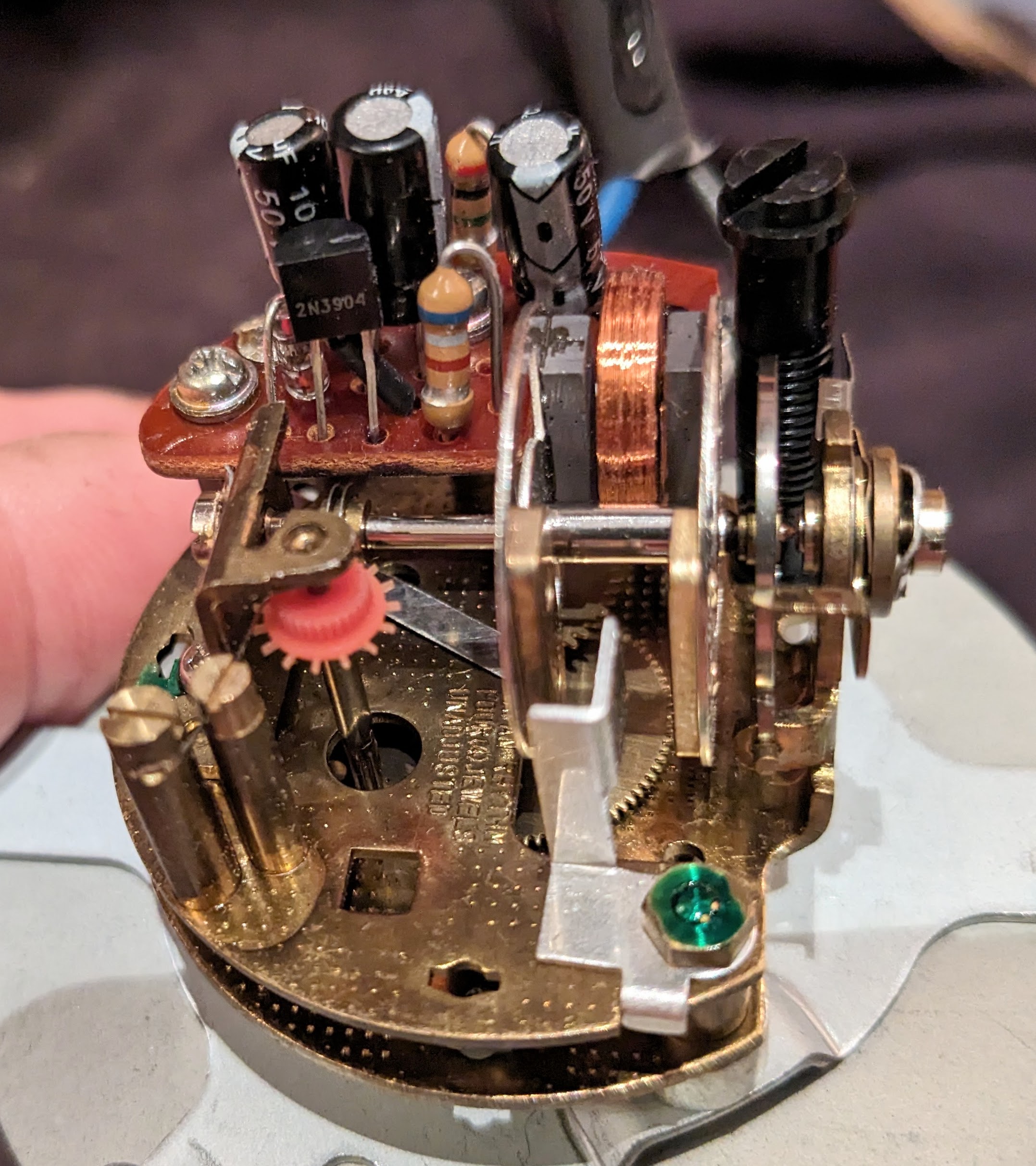
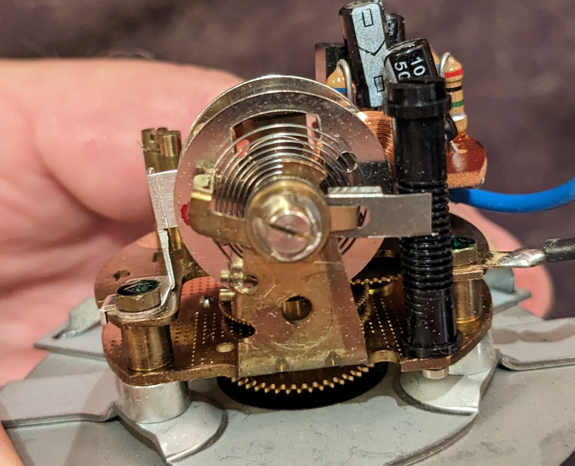
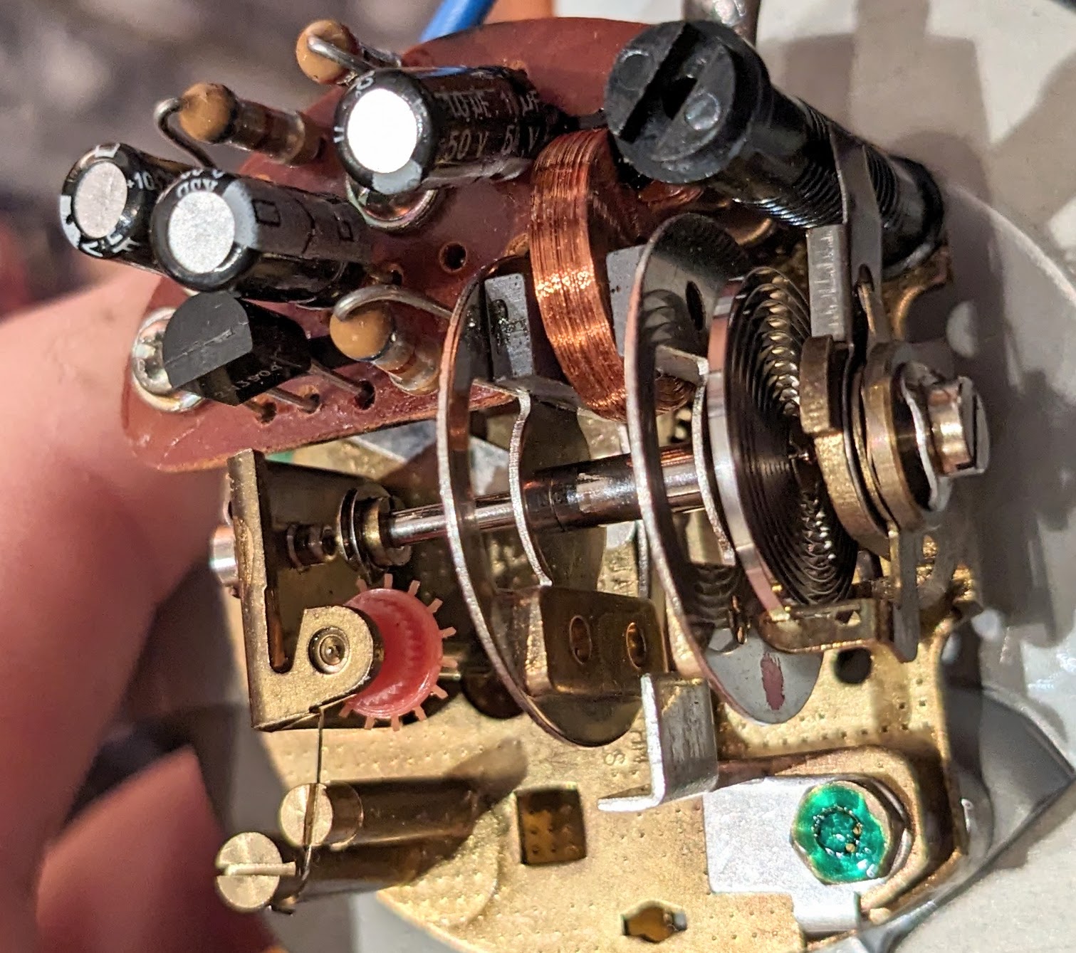
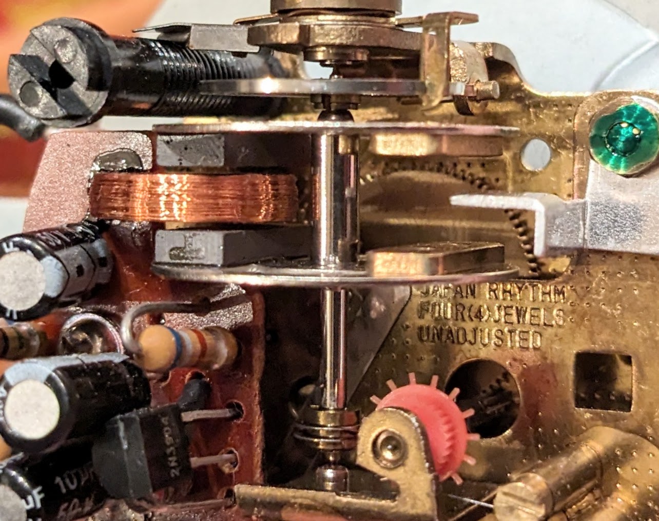
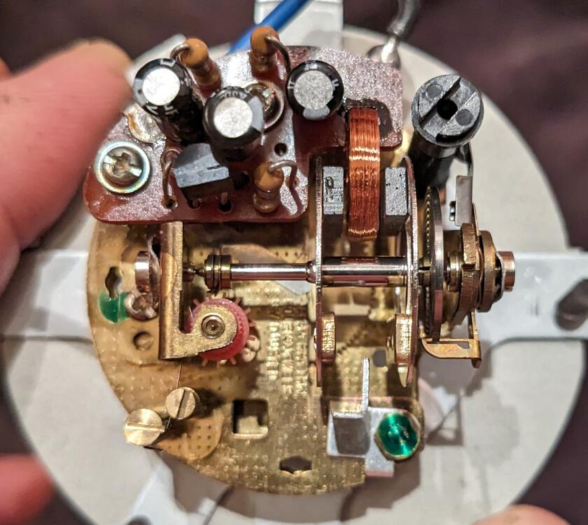
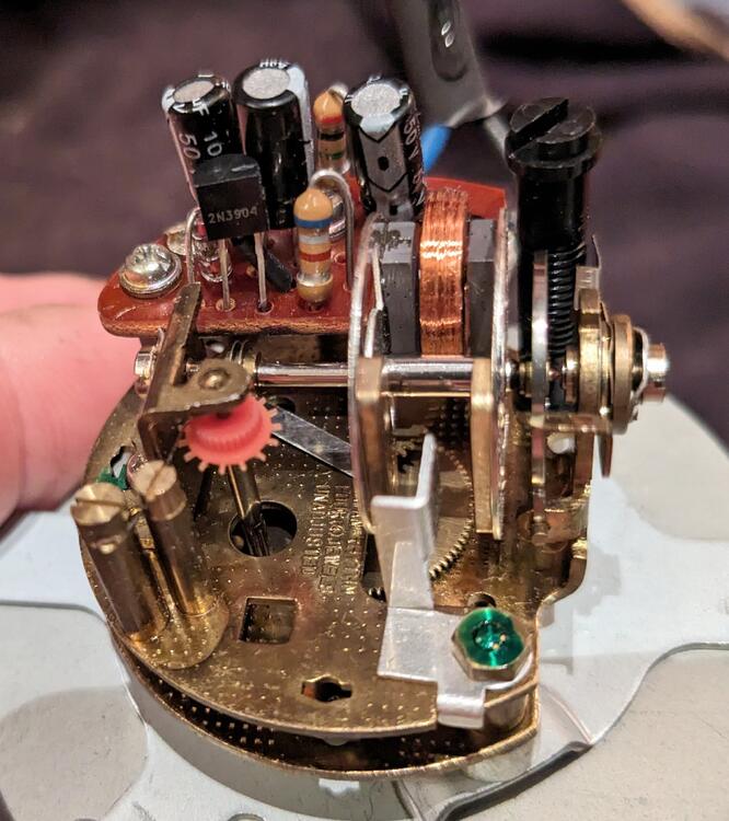
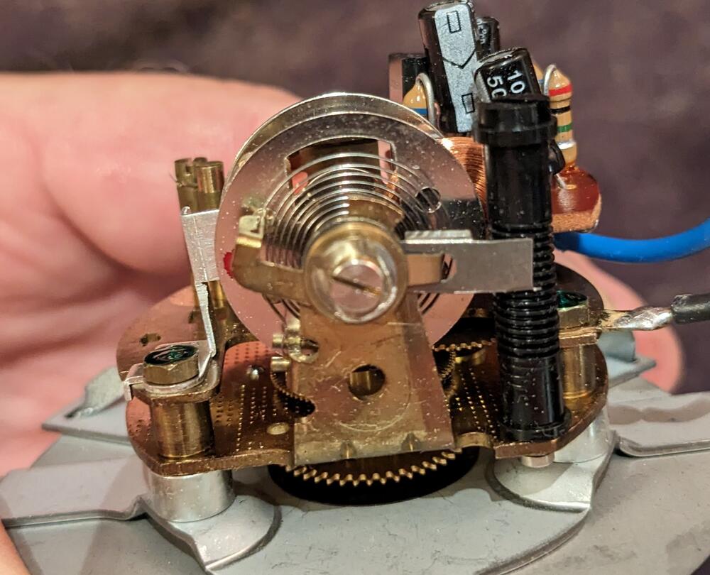
Hello Ron Thank you for chiming in I think I had to jump start it when I did the transistor. The wheel moved when power was applied (which it did not after just the cap replacements), but it did not cycle/swing of its own accord. I ran it for a few days out of the housing. I checked that the shaft/spindle was able to move freely without binding or excessive end play - I had thought perhaps the shaft might have been restrained by the end adjuster, because I had to recenter the shaft when I first took it apart & didn't pay attention to keeping my fingers away from the shaft. When I assembled it in the housing I was very careful to gradually feed/pull the two wires out through the casing as I placed the clock in the housing. There is no signs of wear or degradation to the spring, balance wheel, gears or shaft / shaft tips or pivot caps. If I spin the wheel manually, it cycles for a few seconds. I will take another pic of the clock with the circuit board in place. I was careful to center the coils in-between the wheels. I did not re-use the mis-wired transistor
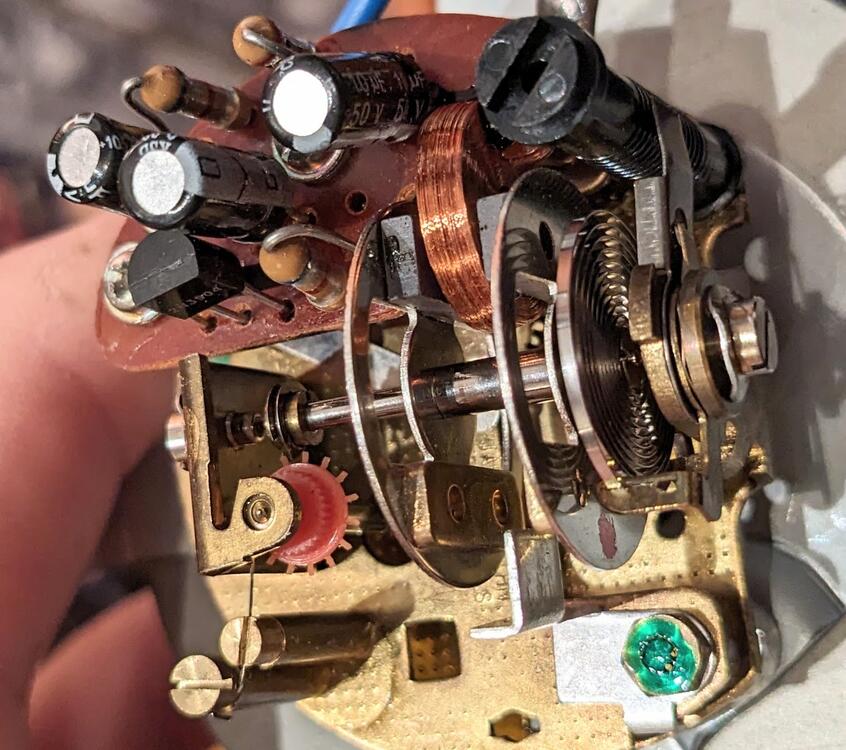
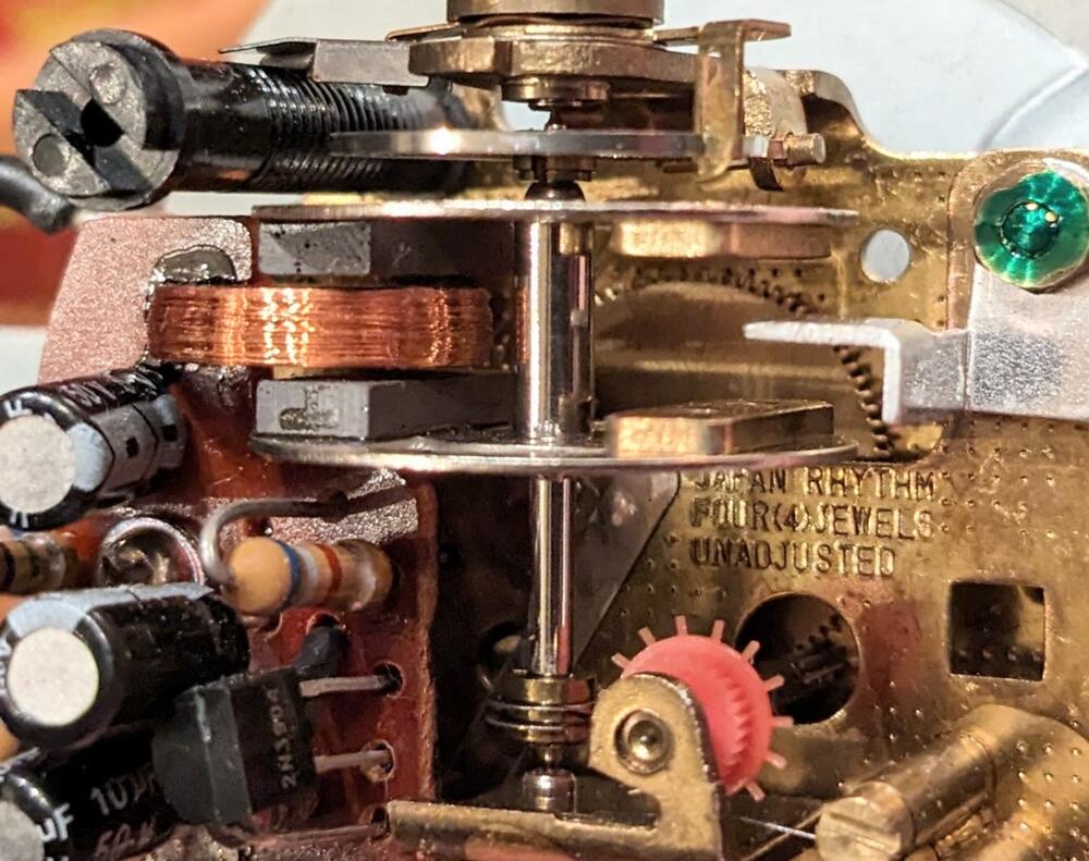
-
Thank you for the suggestion - easy enough to parallel another resistor & drop the resistance on that leg of the board. I'll give that a whirl!
-
Yeah, I wondered why mine seem to flap in the breeze when lowered part way, seemed unlike Nissan given the care taken with all aspects of design on this car. I ordered a pair as mine must have died years ago & been discarded - the bracket isn't there or I would have known to look further into it when I was working on the driver's door.
-
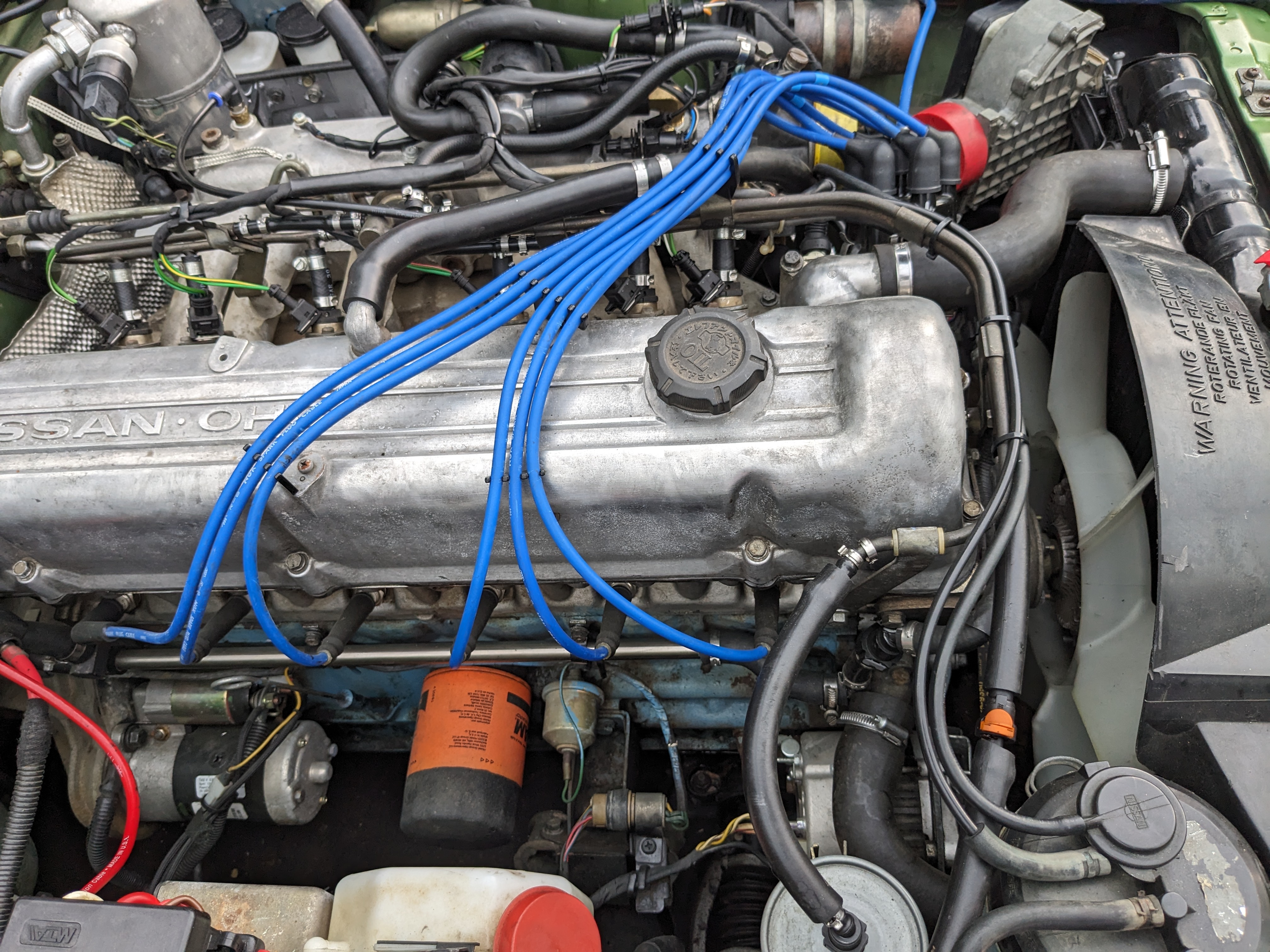
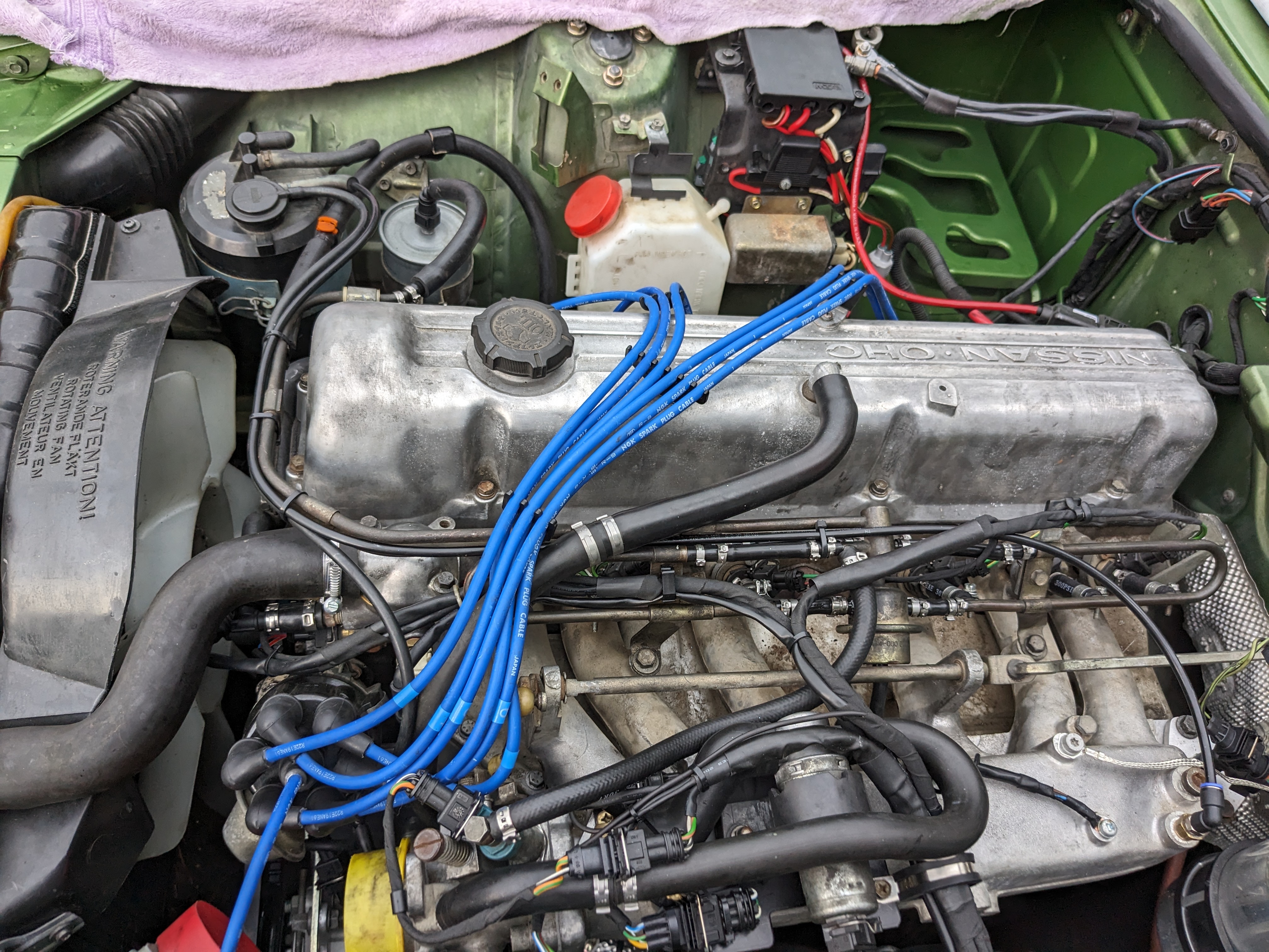
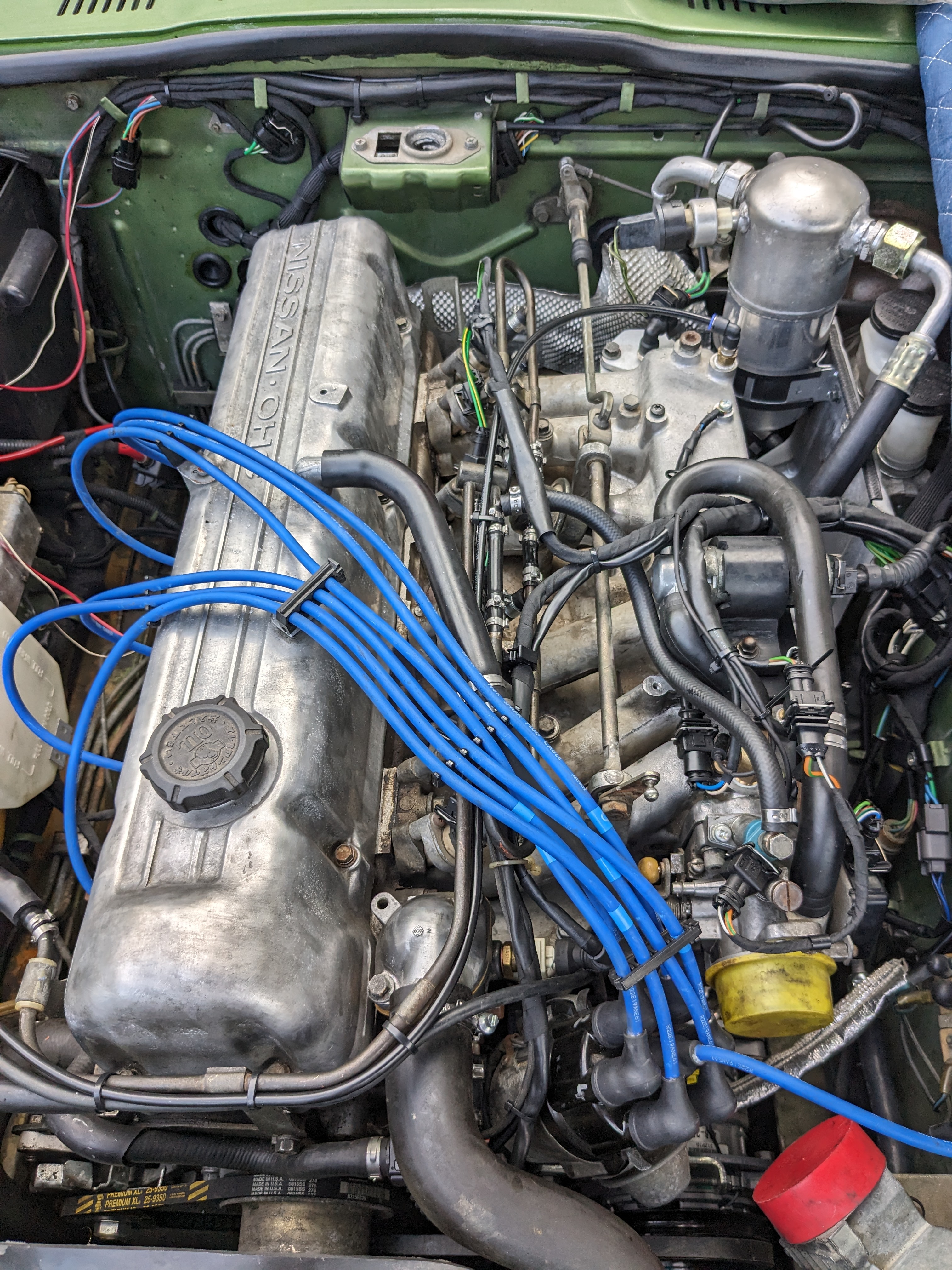
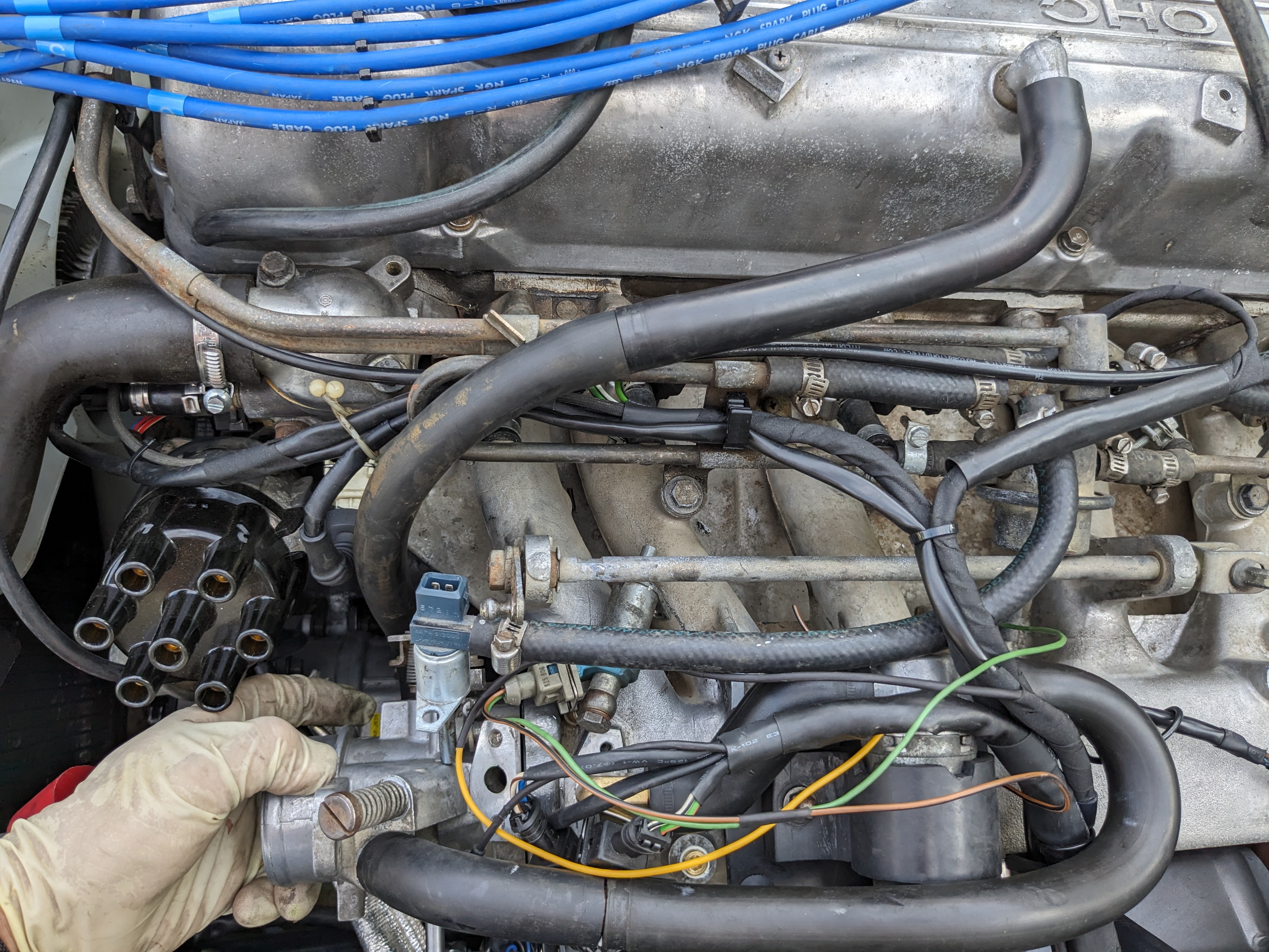
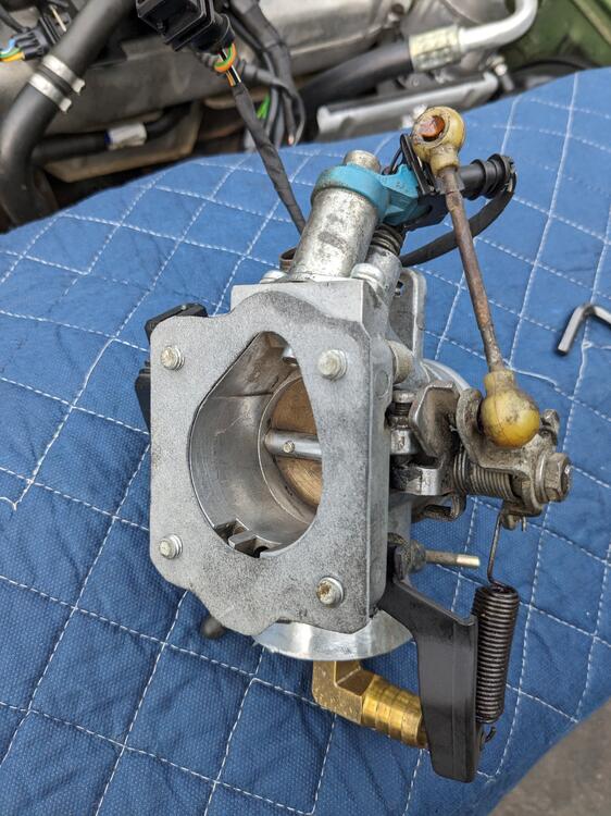
Looking back at the pic of the 78 bay I took, I realized the plug wires were not properly placed - it irked me that they were hanging out on the right side, so I took care of that & made the TB gasket EDIT - the external throttle return spring had a sleeve of some sort inside it - it was cooked, presumably from the manifold proximity, so I'm not sure of the intent. I removed the scraps & put a section of greased nylon (8mm OD) tubing inside the spring.
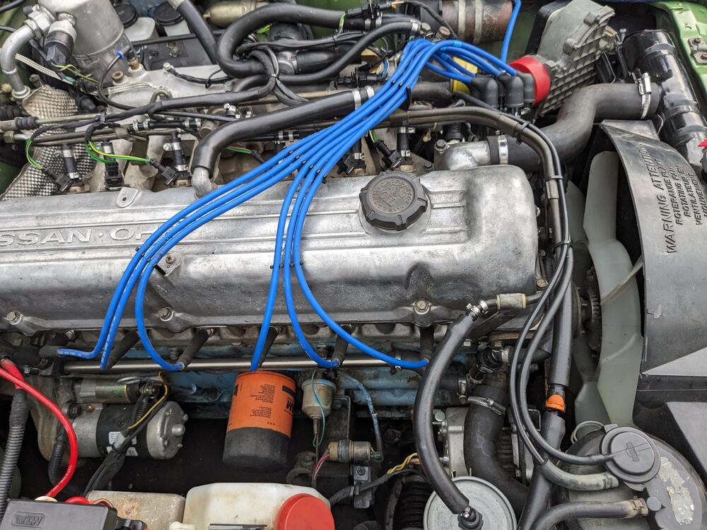
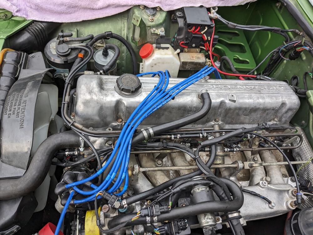
-
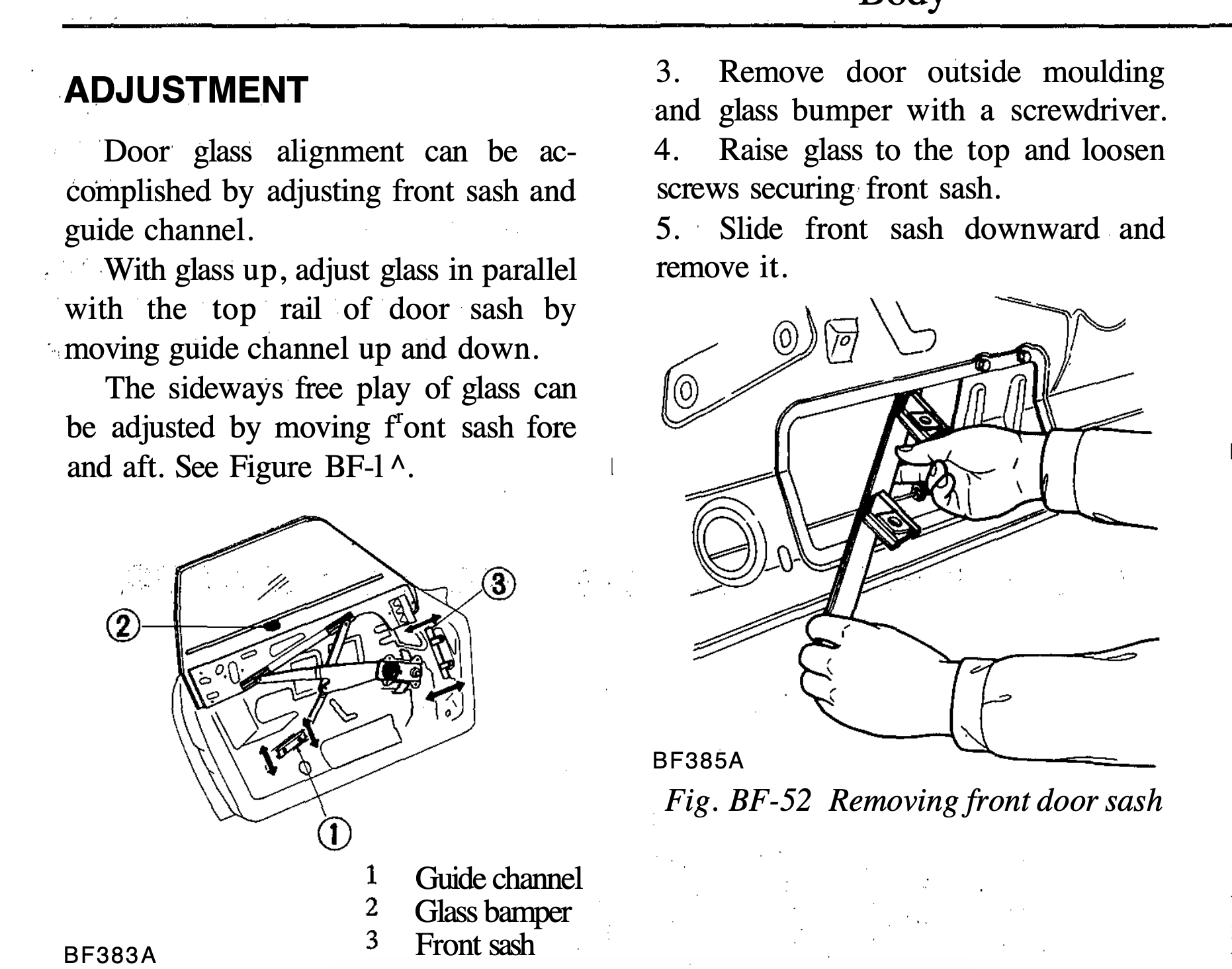
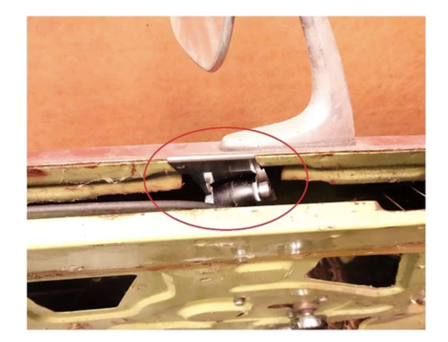
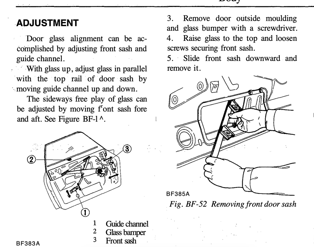
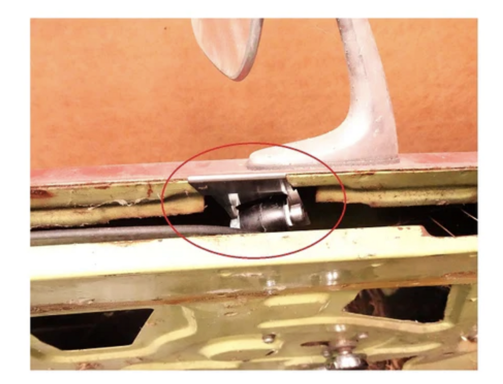
What year is yours? Mine had no extra parts attached - I'm not familiar with the extra pieces that are attached to yours at all. I see now in the manual there is what they refer to as a "Glass Bumper" looks like it's supposed to be somewhere in the middle of the door? That is MIA in my door. I had the whole thing apart when I fixed the door card. Do you have a bette picture of it? EDIT - never mind, found them on ZcarDepot - they also show where it needs to be installed
-
Honestly, I can't recall now if I 'helped' it. I left it running for a few days off the battery & it kept good time. I'm going to assume I helped it, since it clearly won't jump start itself. Not sure where that leaves me.
-
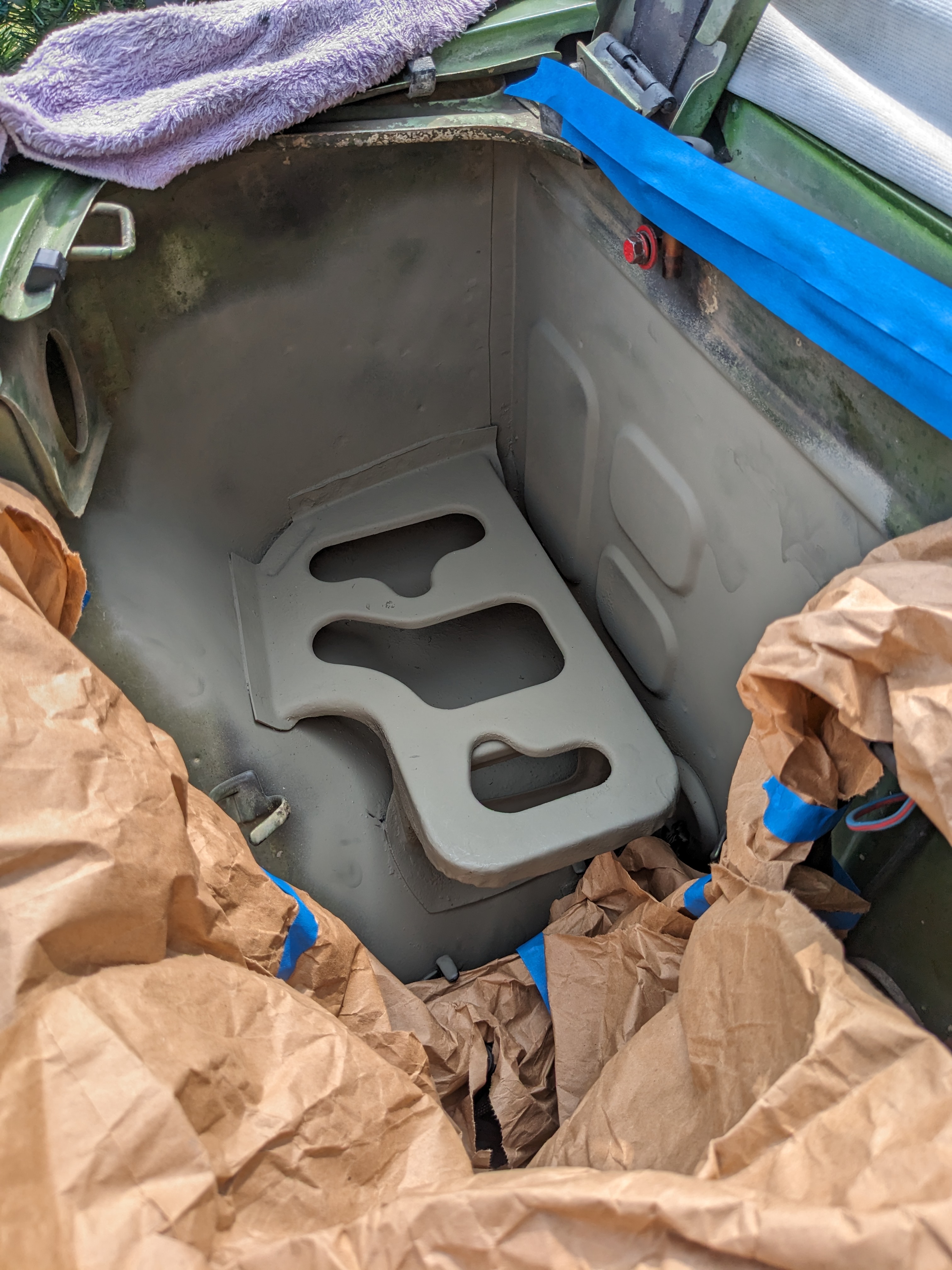
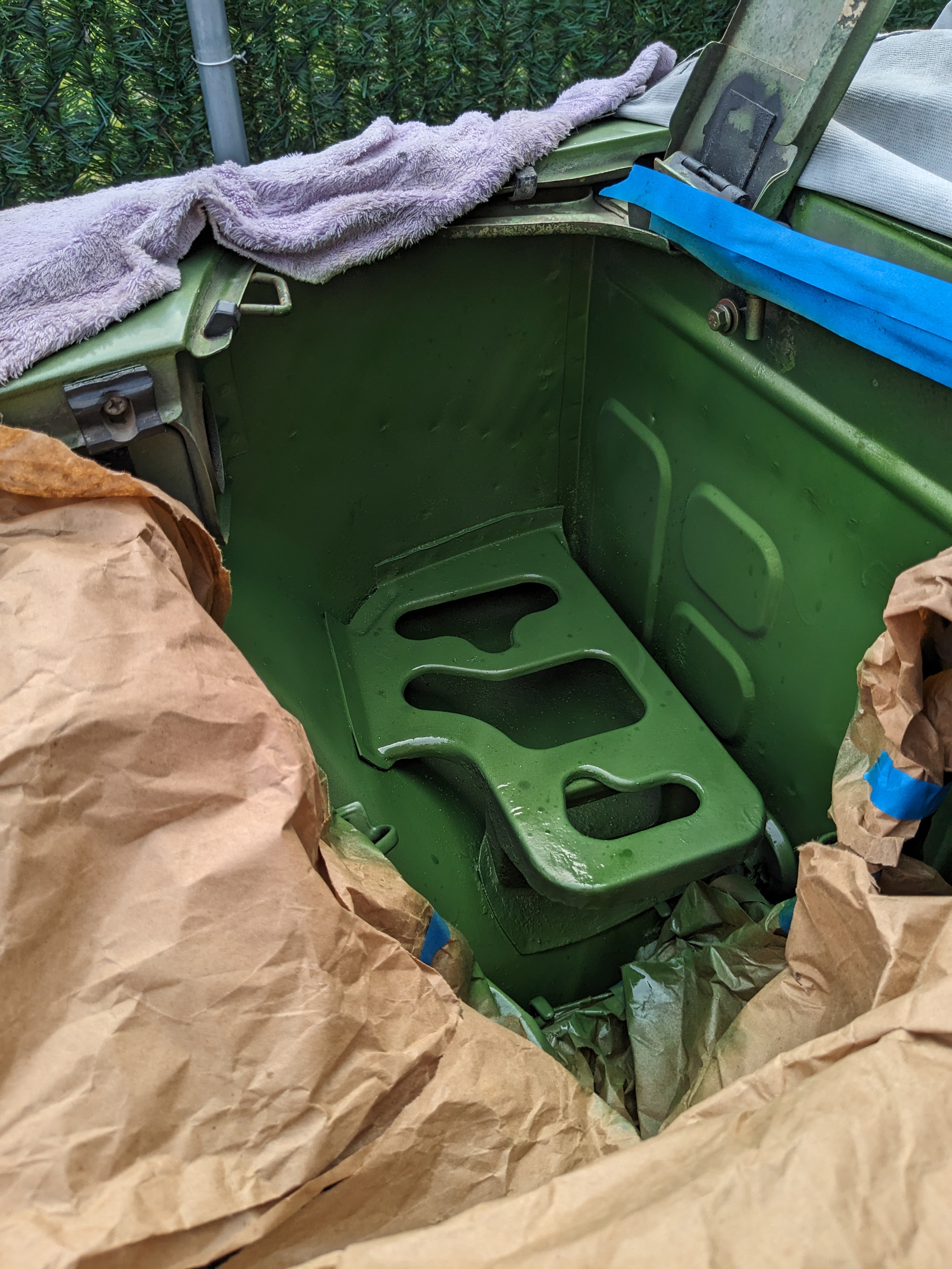
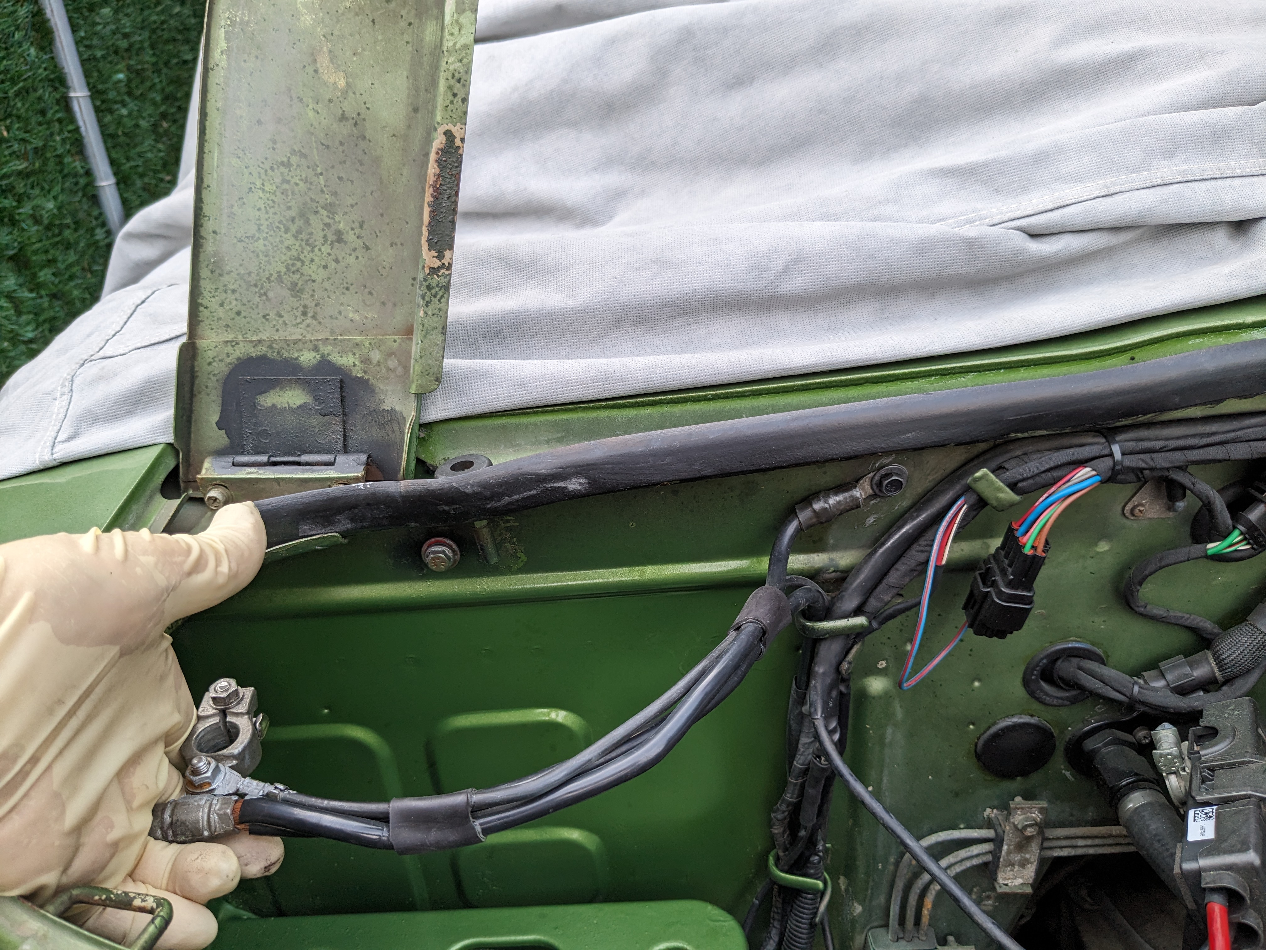
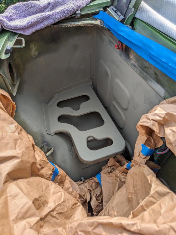
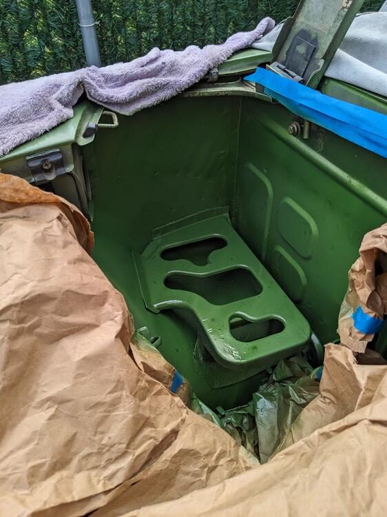
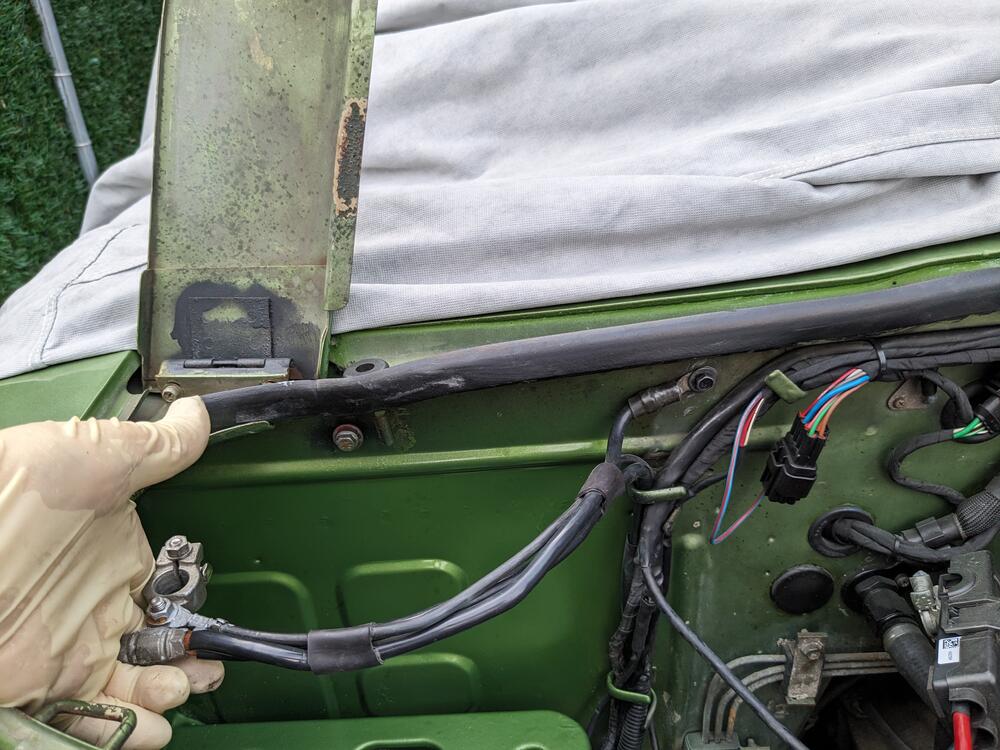
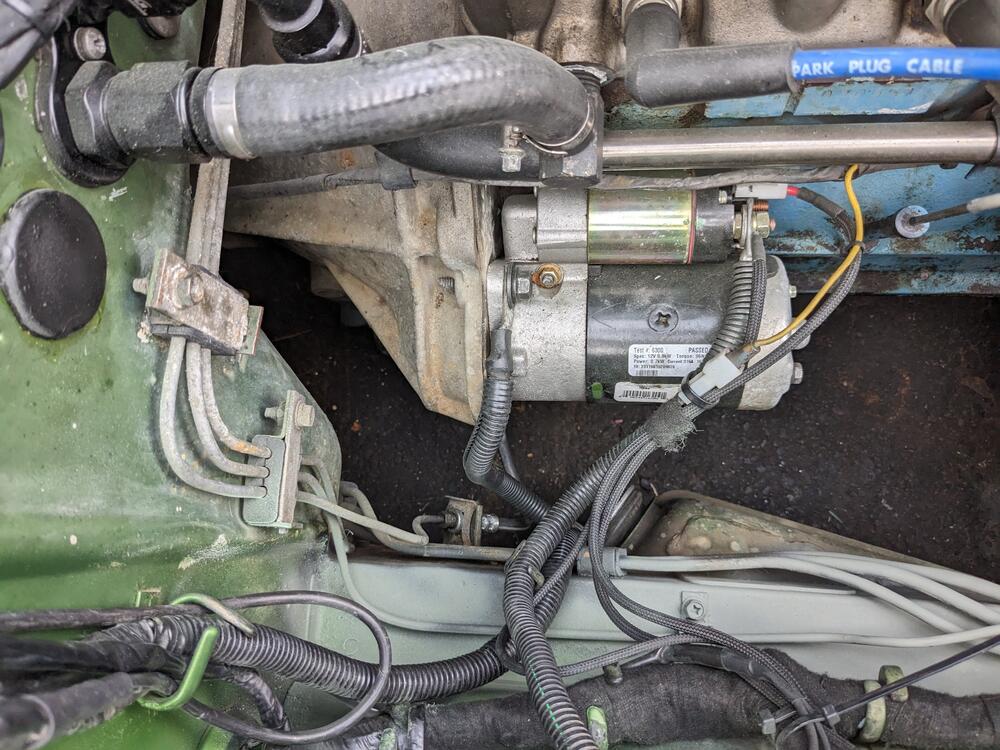
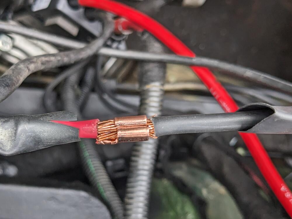
Since I had to add a power supply for the AC fan, I removed the battery & also replaced the negative cable with a Volvo part (2005 S40) that incorporates the body ground leg. I had previously treated the rust on the battery tray, so I primed & painted the area while the space was clear I added the EMS ground to the battery terminal with a ring terminal, and got rid of the old spade connection So, ground to engine, body & EMS
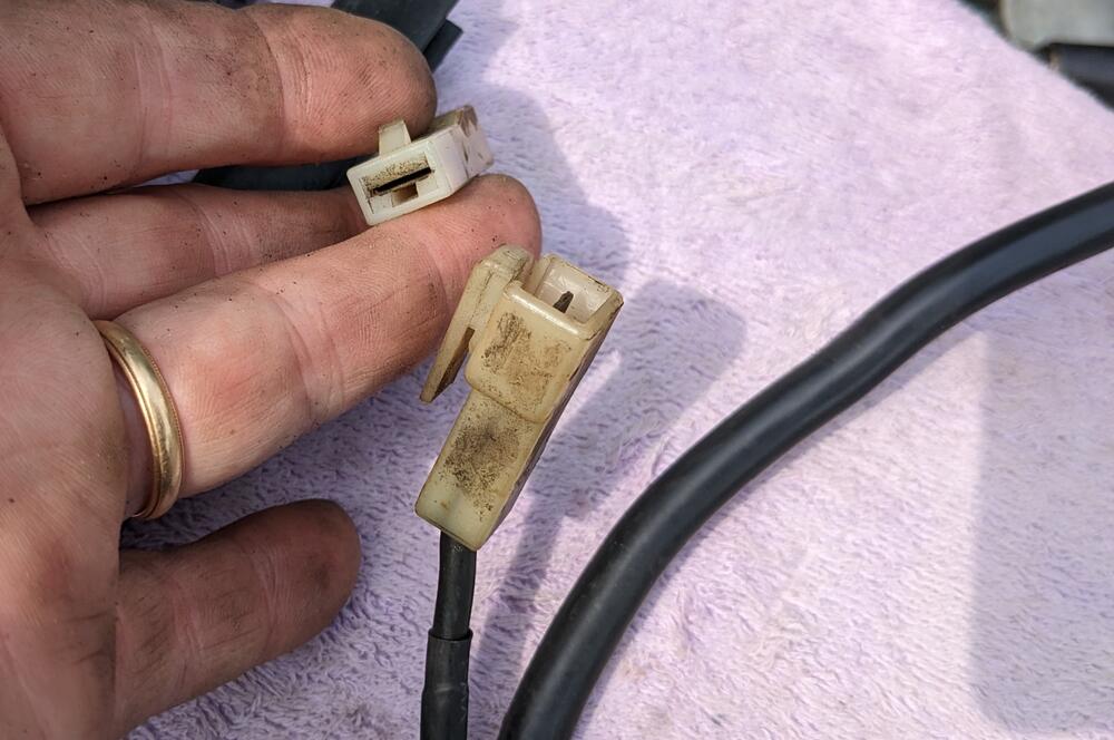
-
So, I spoke too soon. The clock worked, but after I reassembled it in the case, it did not. Pulling it back apart, as long as I 'jump start" the wheel, it will run continuously after, but simply connecting it to 12v, nada.
-
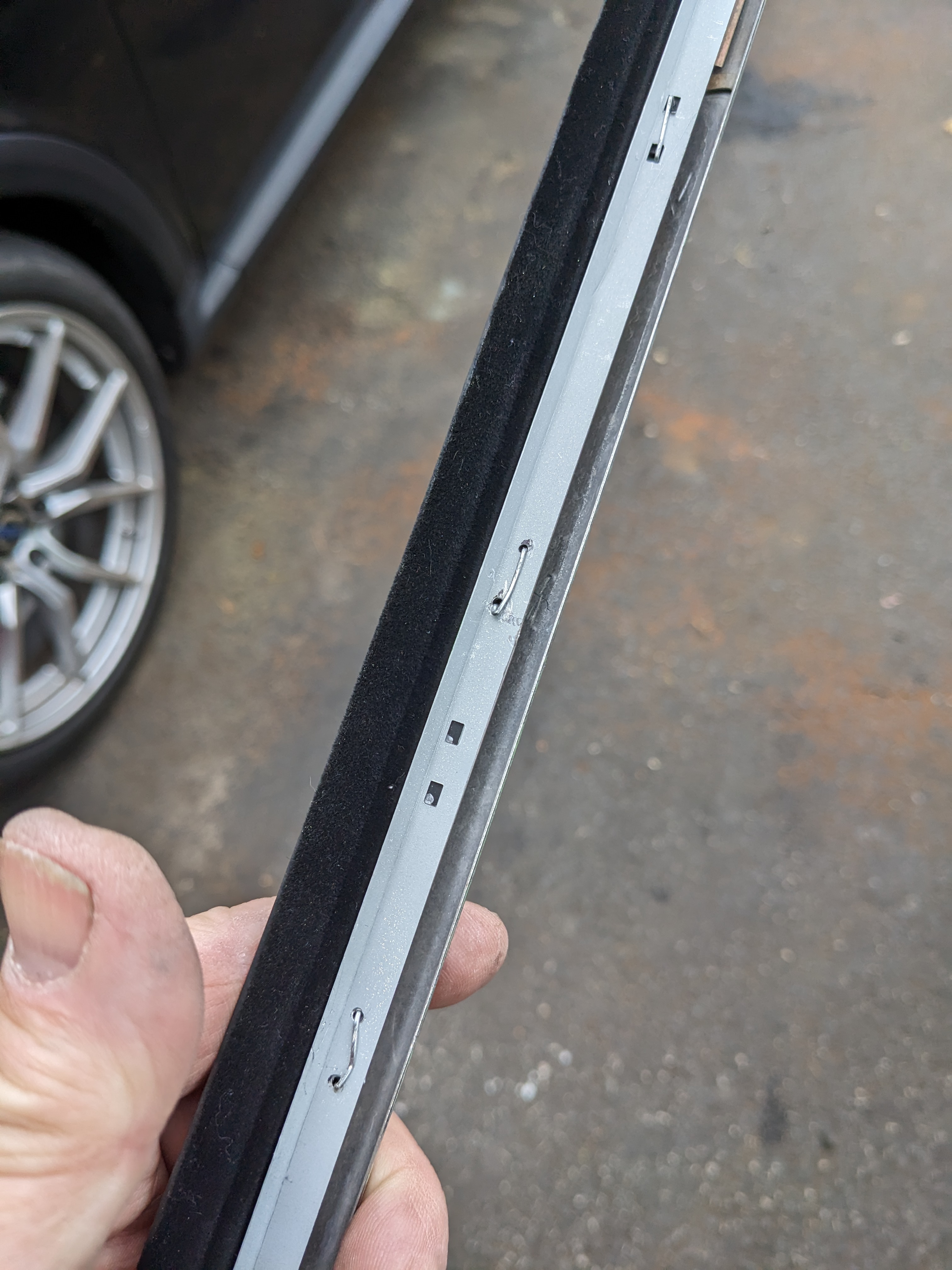
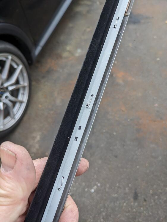
Nothing inside the door is touched. It's pretty easy to remove - you may be able to lift the rear corner by the glass frame, and simply lever it off. There are 3-4 clips inside the channel that clip onto the top of the door skin lip. If yours won't pull off that way, you can use a putty knife with a layer of tape on it to prevent scratching the paint, tuck it under the rear edge by the door glass frame, and lever it upwards. Once you have it started, just pull it off by hand a s described before.
-
Yeah, I already bought the rubber squeegee & replaced one - the issue for me is that one of my moldings is damaged & I don't want to look at it, hence the full replacement.
-
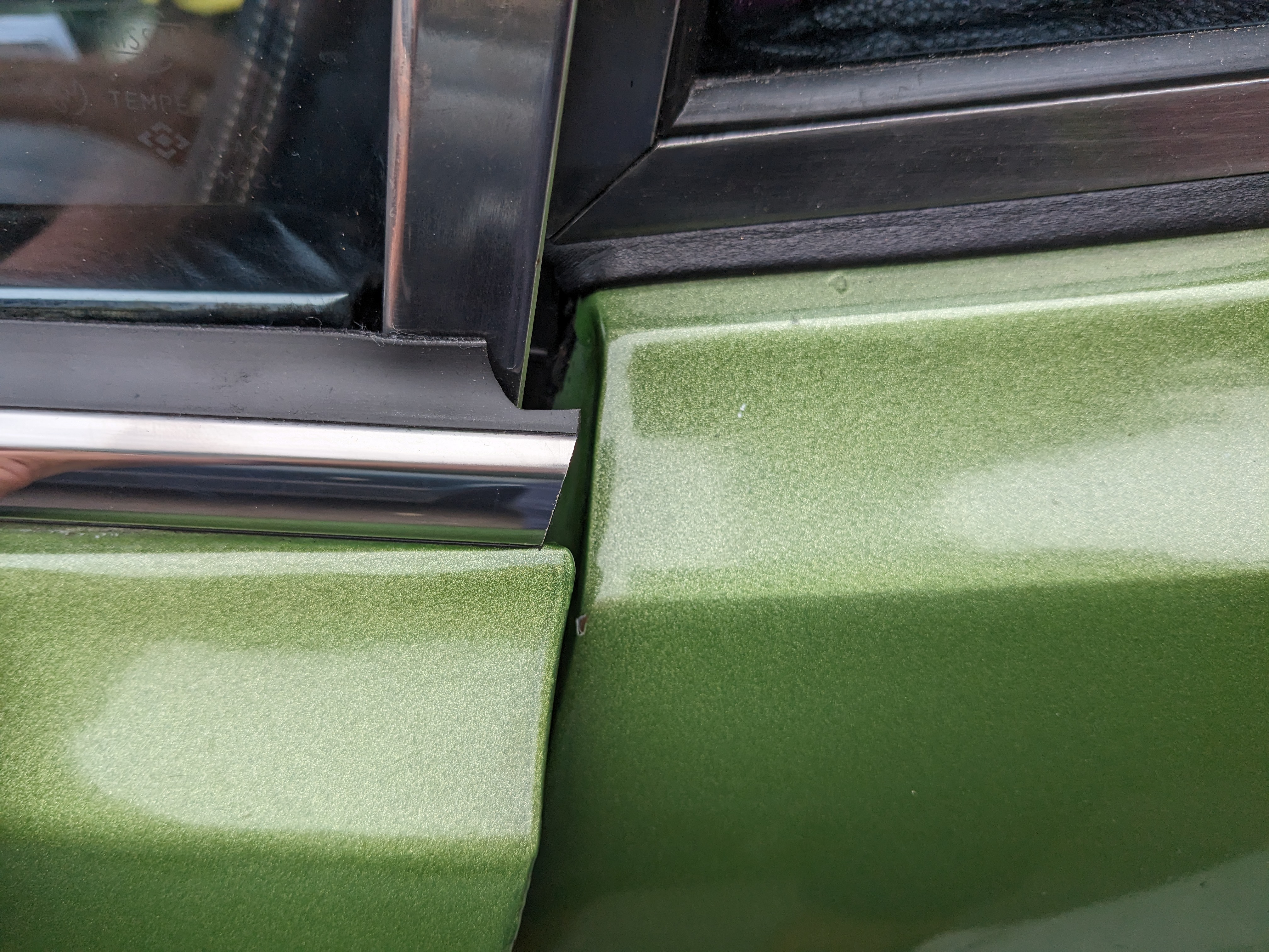
Wondering if anyone else has purchased & installed these moldings. They are very nicely made - BUT - they are not pre-bent to the door cap curve. Website just says bend to fit, and Edan unfortunately is not good at responding in a timely manner or actually answering questions about the products he sells. All he said is that it bends easily, when I asked pre-purchase. I have tried to get more specific directions from him directly, to no avail. Since the molding is flat, I can only 'assume' the contour will correct once bent, however I'm still unclear logistically of the best way to do this. If it would bend easily, one could simply press it down on the door cap to shape it, but that is not the case. It's gonna scratch the paint at the very least. If you have removed these, you know the factory molding has both a fore-aft bow, and a 'in-out' curve to it. I don't want guess with this, they are not cheap. So, has anyone else played with these?
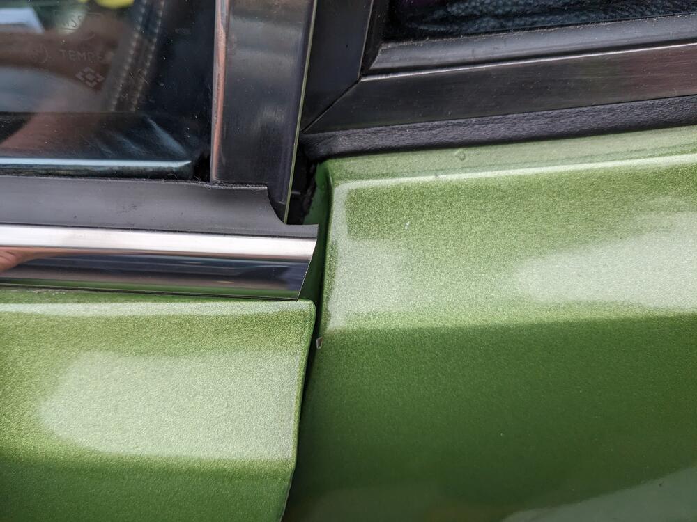
-
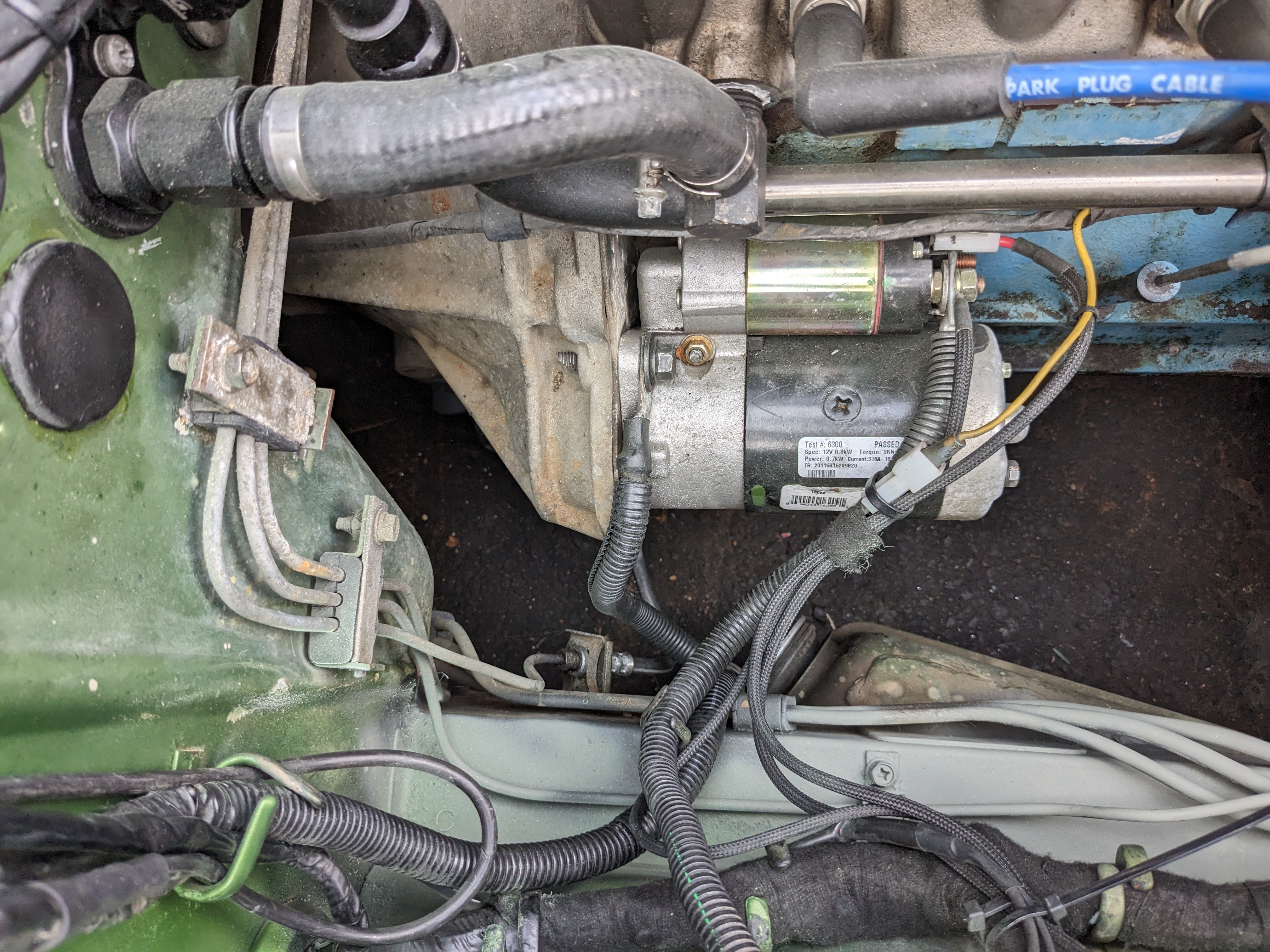
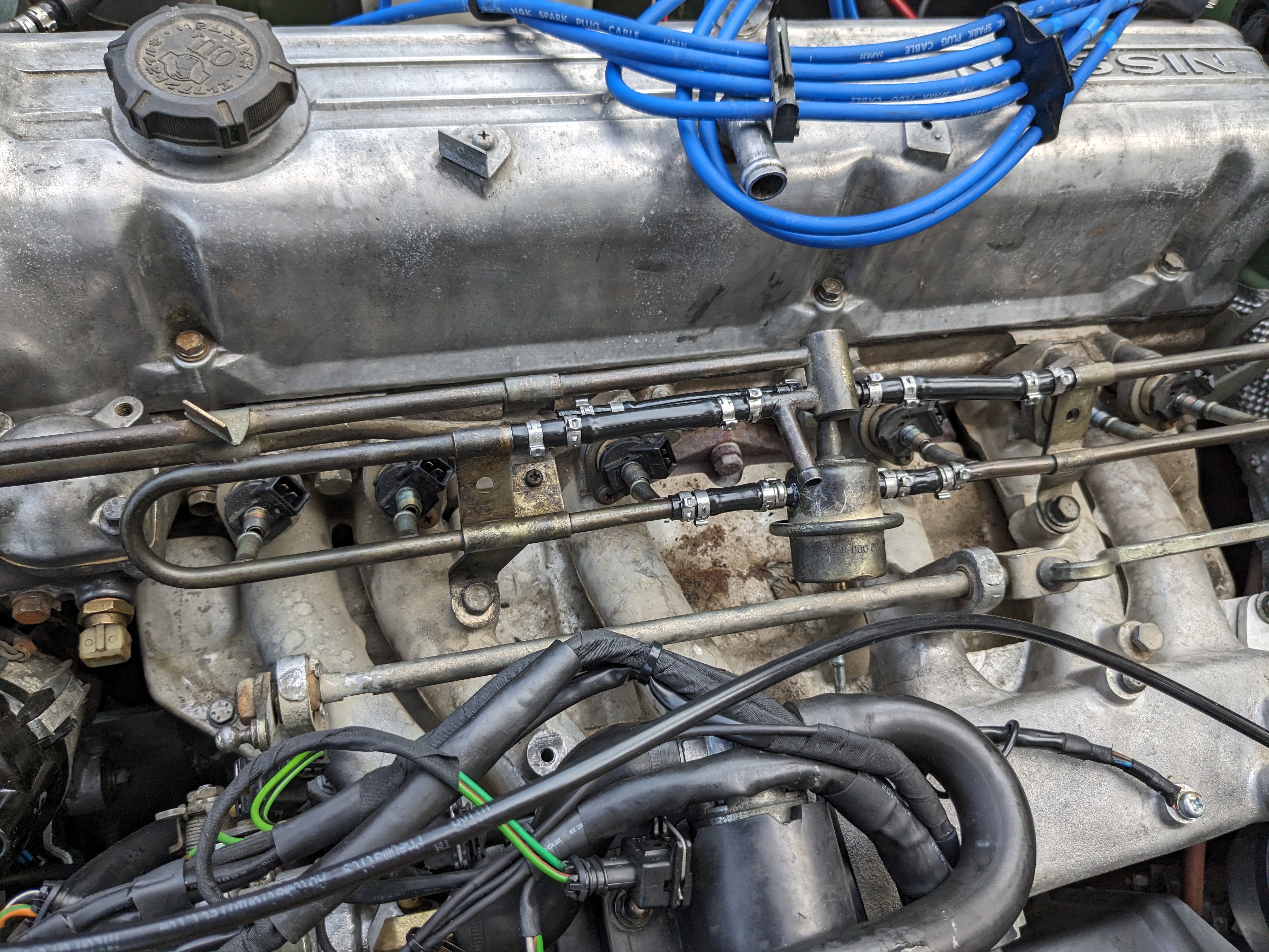
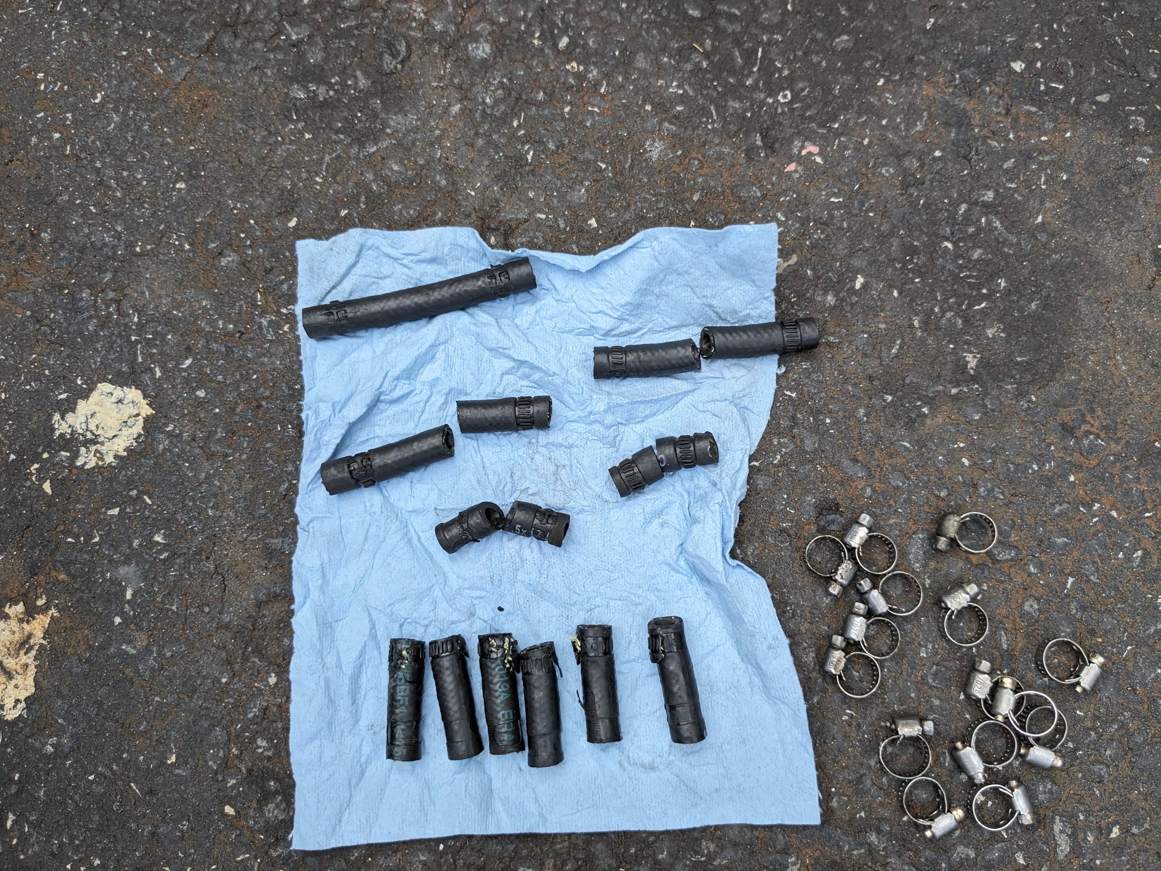
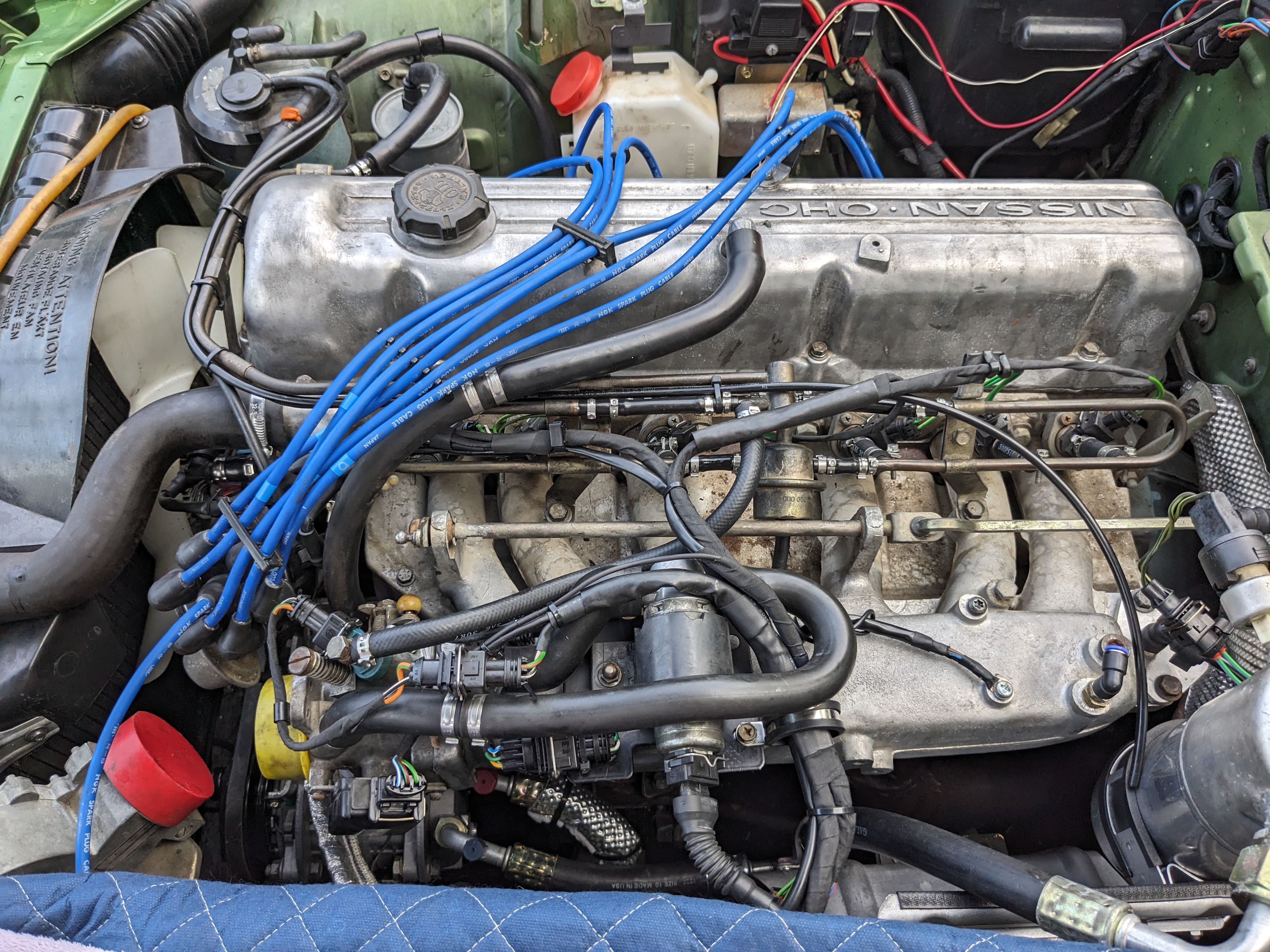
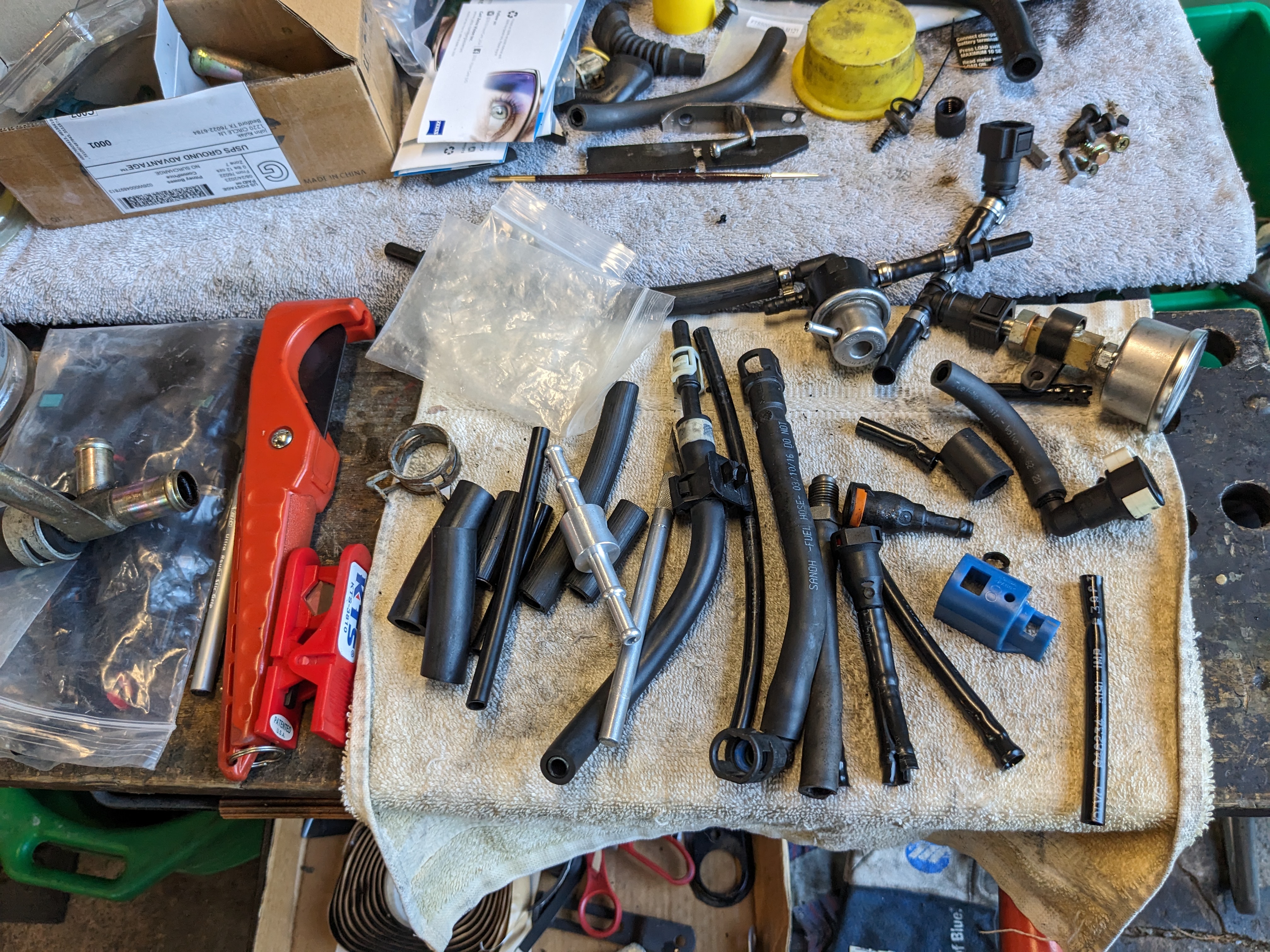
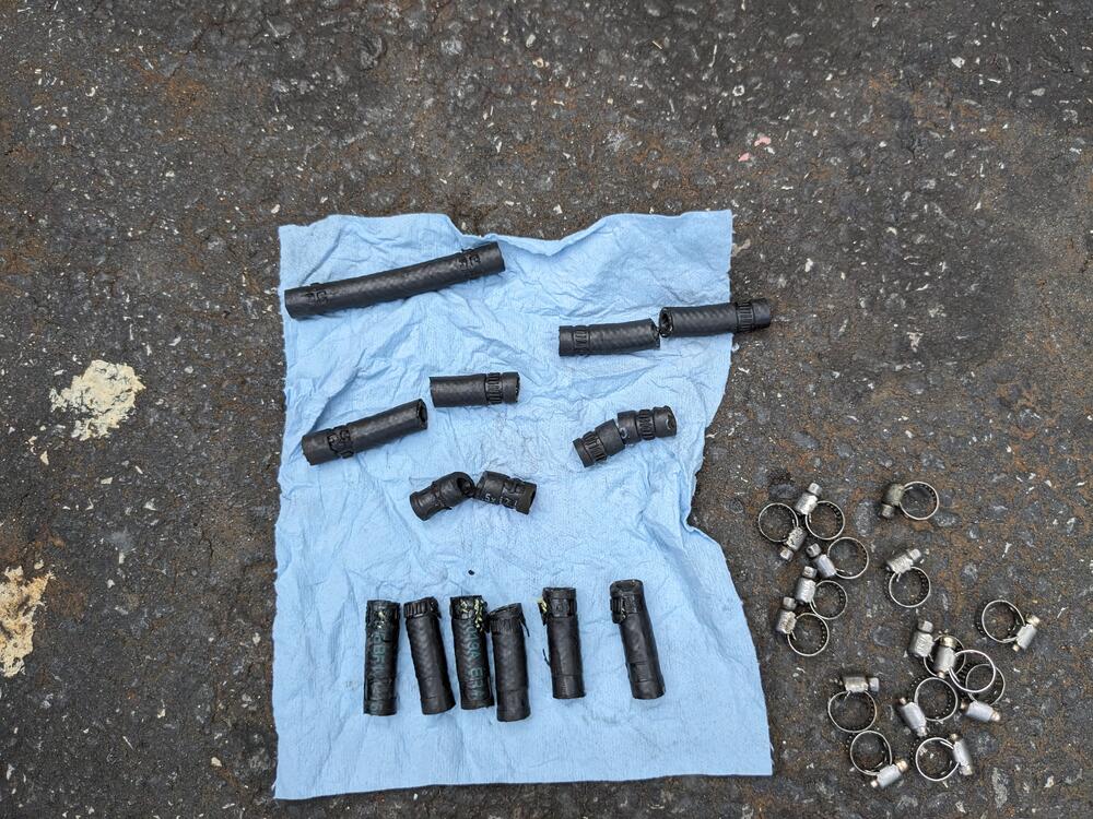
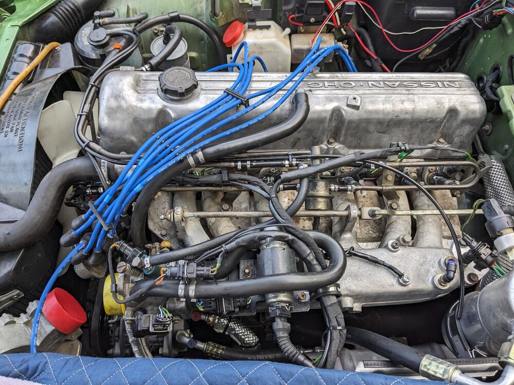
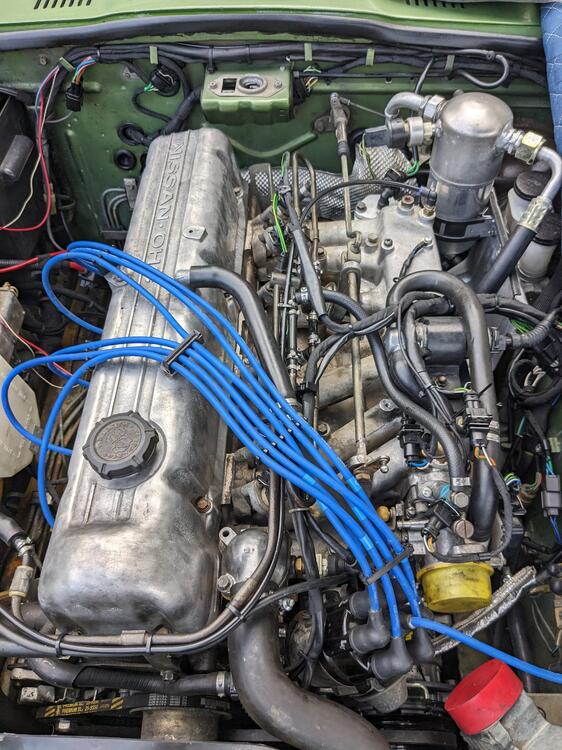
We have thunderstorms coming in, so I worked on getting the wiring & fuel hoses done so that nothing is exposed, since I have the hood off. Removed all the fuel hoses. The injector ones were too long - approx 2" - the rail was set such that the FPR was touching the accelerator link arm. Lots of worm clamps 😞 After I replaced the rail hoses with sections of 10mm ID nylon fuel tube I put the rail back in place to measure the injector hose length. I reckoned 1.75" would be more appropriate & not lift the rail Most everything back together, so now I just need to make a TB gasket, bolt the TB back on, wire a couple connections for the AC in the bay, remove & drain the AC compressor, refill with PAG46, then I can move on to all the wiring under the dash, then get the dash back in (eventually).
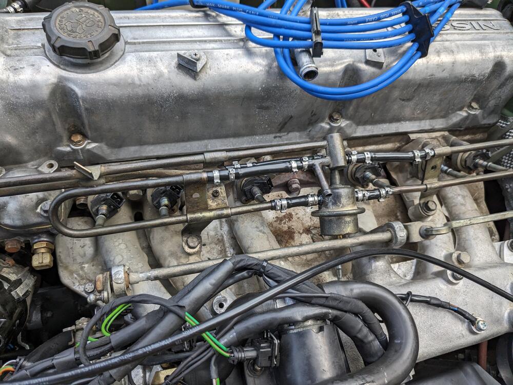
-
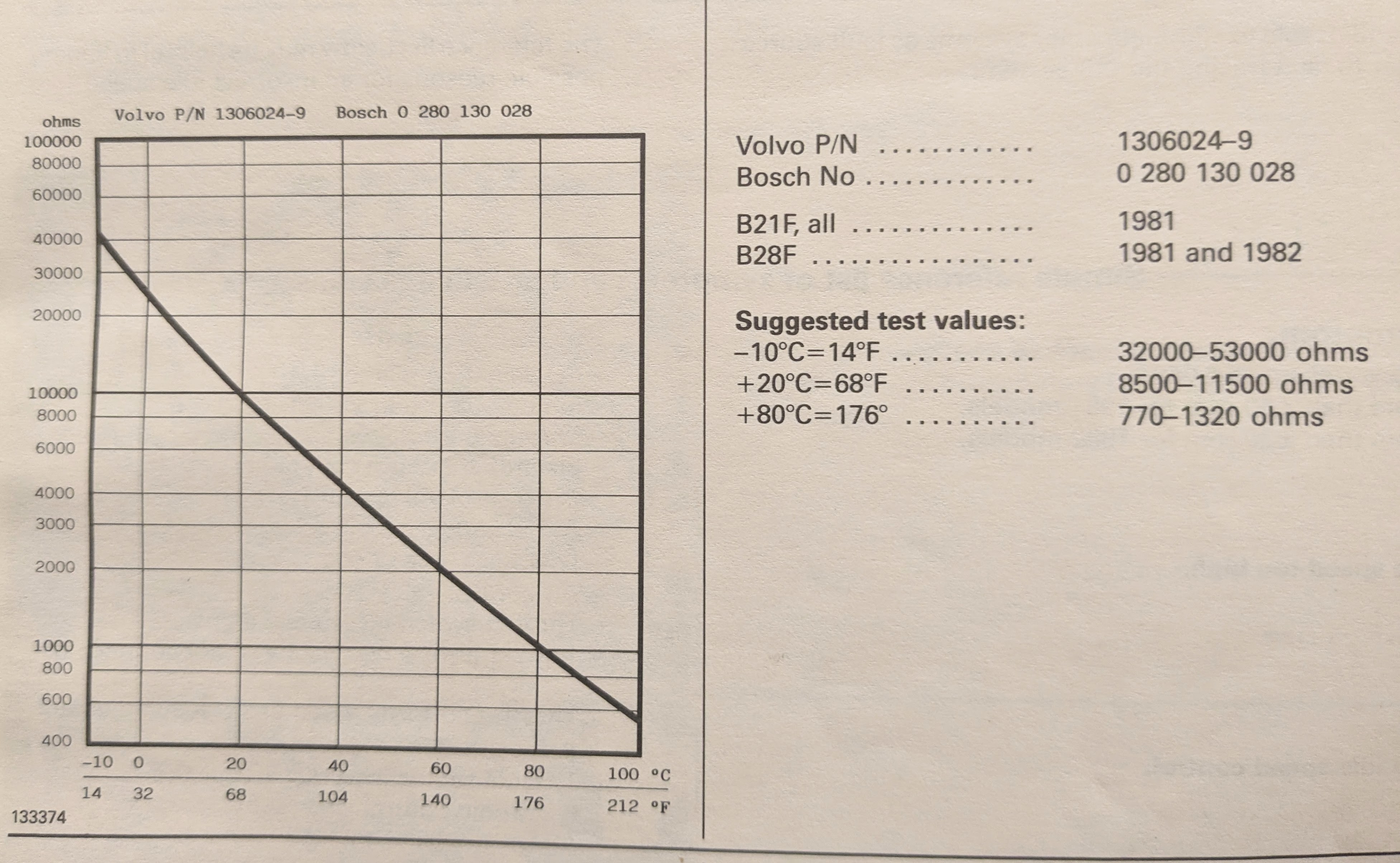
OK - so I already installed the one 028 sensor in the cooling system, so I searched through my Volvo manuals, and found the chart - the axis is reversed compared to yours. it's much more linear though

-
Apologies - I missed the clarification. Volvo only gives those two points. I'll put the one I have in heated water with a thermometer & get some other measurements over the next day or so.
-
I put the Volvo test values in my post above 😁 8500-11500 @ 68ºF 770-1320 @ 176ºF
-
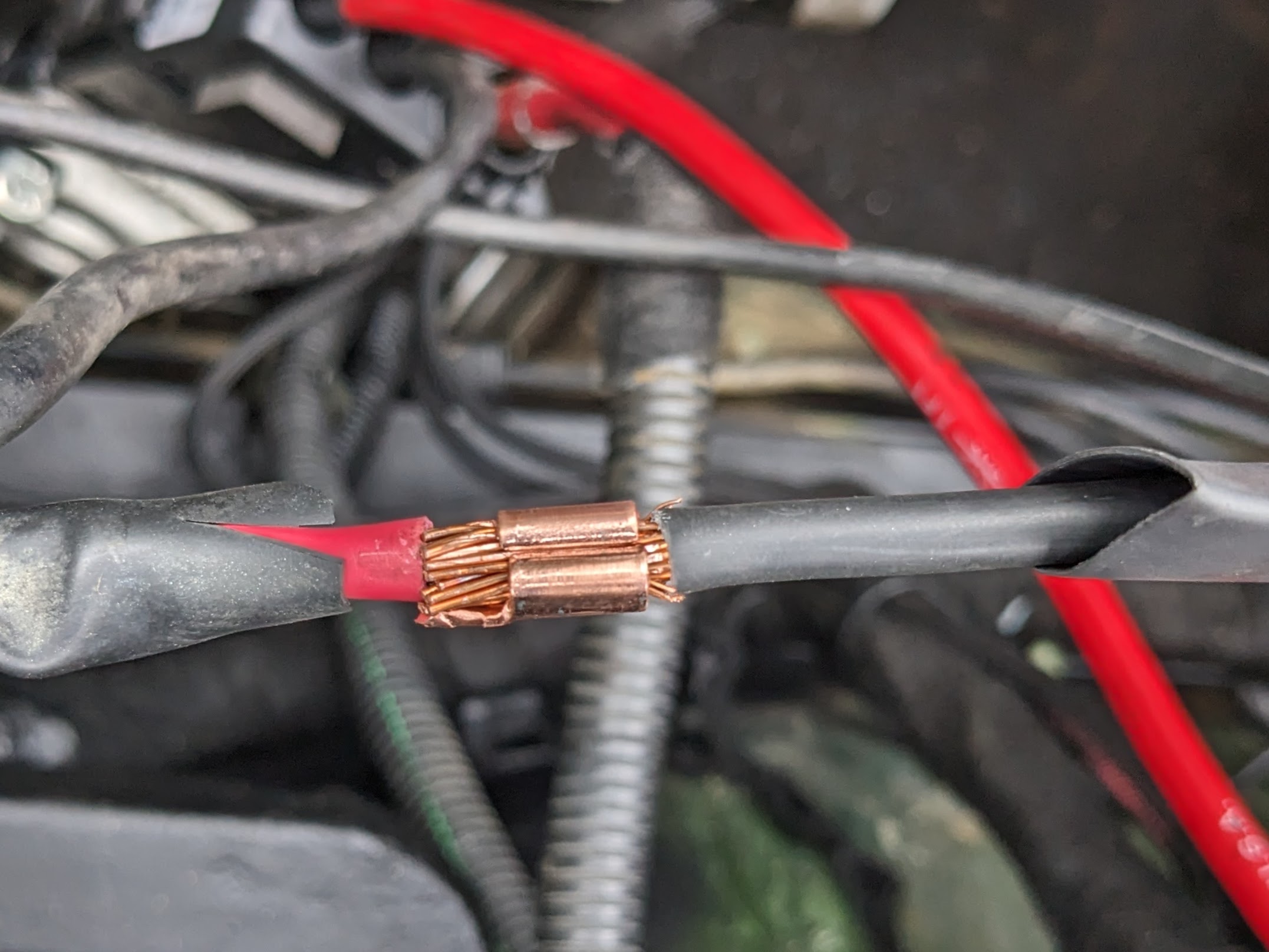
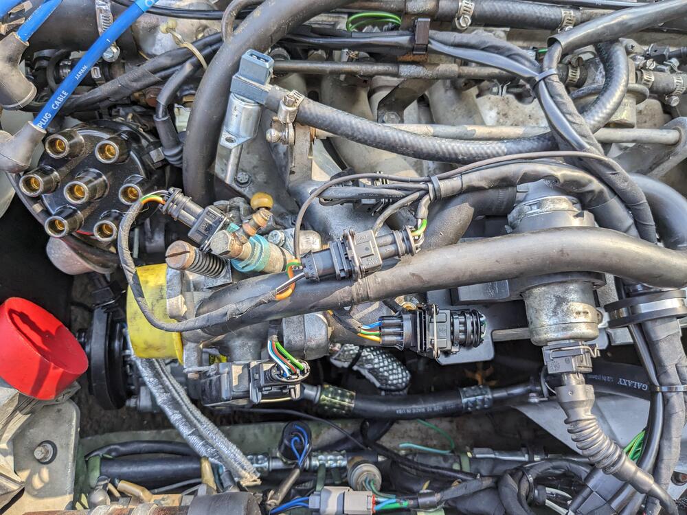
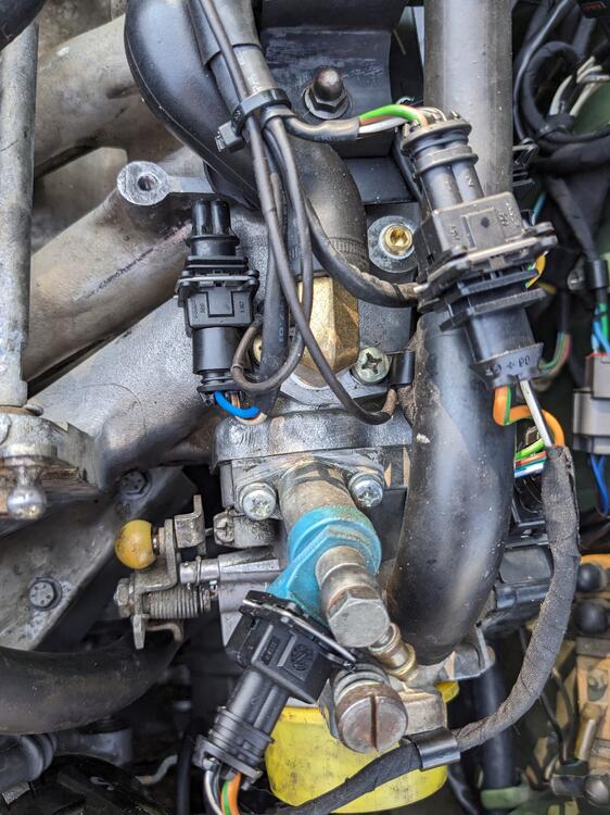
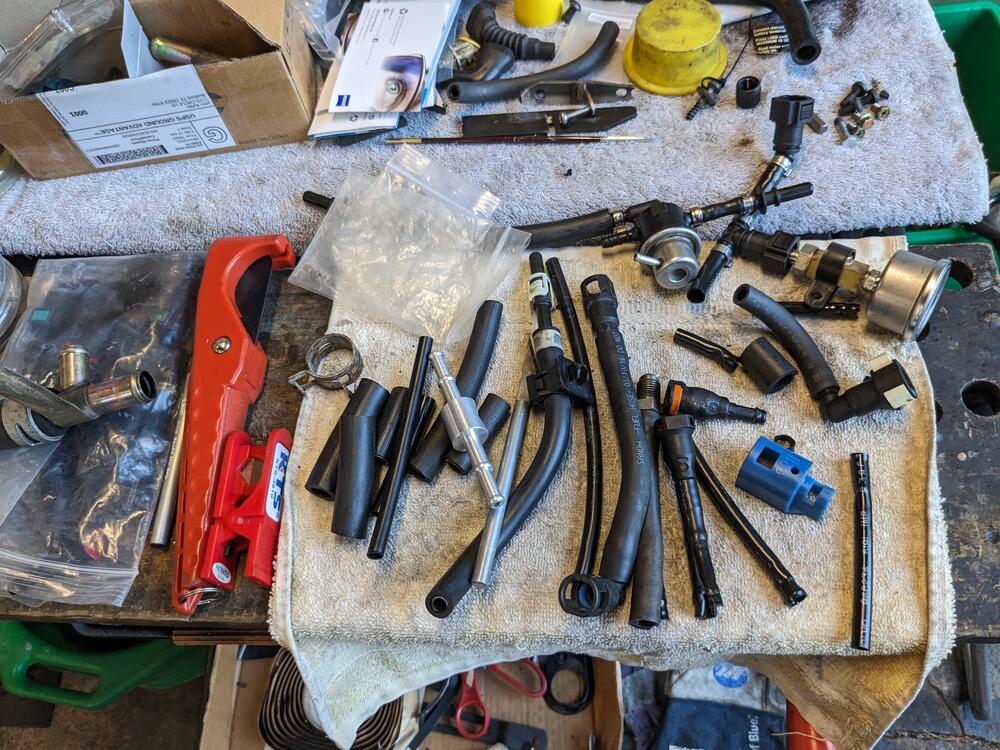
Minor things after work today. Temps still in the 90's & humid - not pleasant working outside. Made the harness extension for the CSV & bridge harness for the TPS to incorporate the signal wire to the CIS module. Next I'll need to pull the fuel injector rail & replace all the fuel hoses. I spent an hour figuring out if I could fit the Volvo FPR pod on the right side near the filter. Not going to work with the existing layout, the angles are all too acute, it would end up stressing the fittings on the pod itself, which is plastic. I'll have to think a little more about that. The only reason I'm bothering is I'd rather rework that while I have the rail off.
-
Thank you, CaptO :) Any chance you can overlay the 028 values? I have no idea if the curve is similar, even though the values greatly differ. Those two I listed are basically it for all Volvo K-Jet, Fiat L-Jet & Volvo LH2 (either white or blue contact housing). LH2.4 & newer use a 2-path sensor with the same form factor, but black contact housing. I don't know about other marque applications.
-
On this note - I have to search through my old Volvo "greenbooks" - the FSM's typically display resistance curves for the various sensors used with the changing EMS's from K-Jetronic in the 70's thru the various permutations of LH-Jetronic that run into the early 90's. There would be at least 4 different ECT's, and the values of them are definitely not even close. The two I have at hand are 0 280 130 028: 8500-11500 @ 68ºF 770-1320 @ 176ºF and 0 280 130 023 (or 026): 2100-2900 @ 68ºF 270-390 @ 176ºF substantially different values.
-
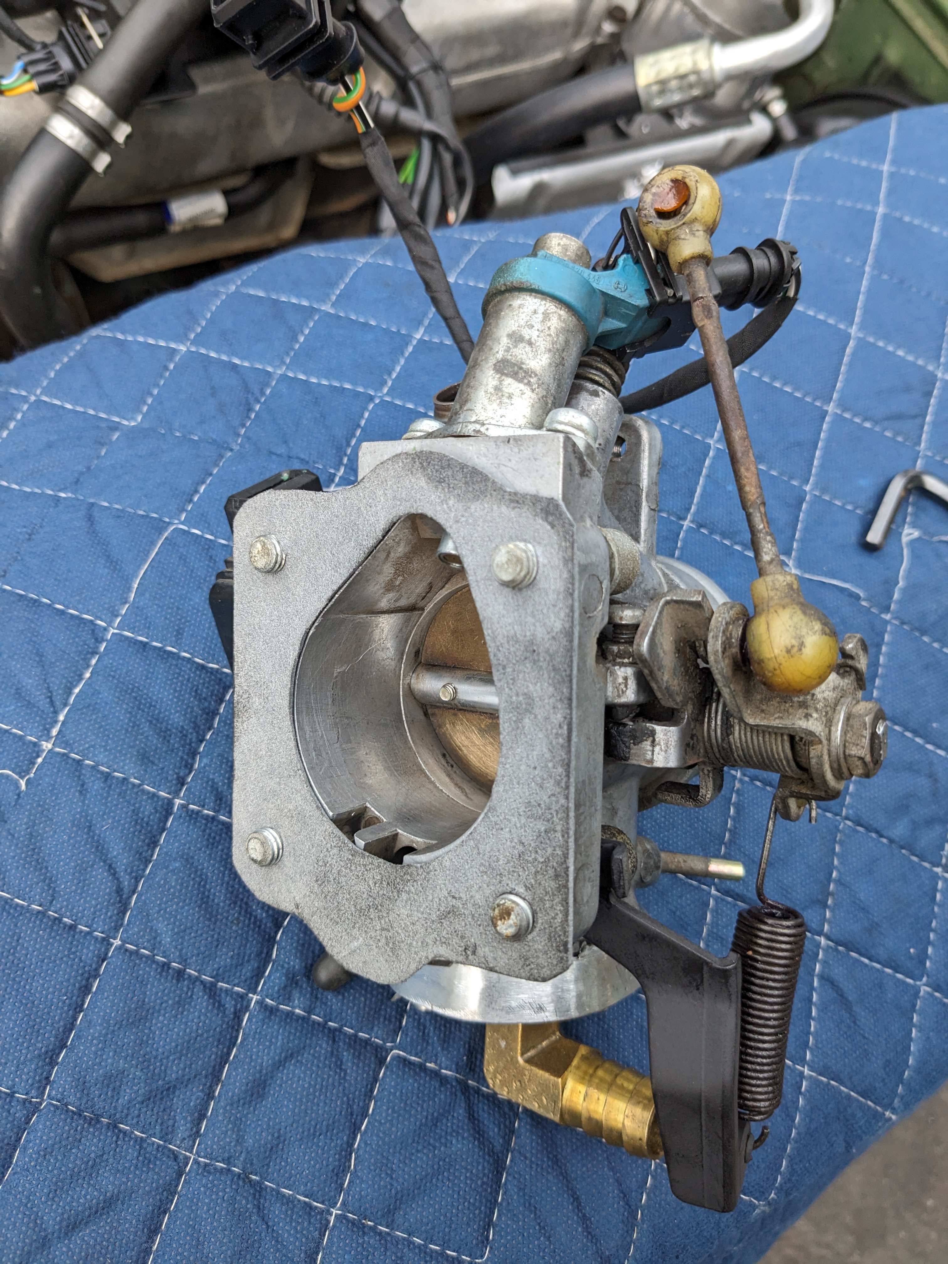
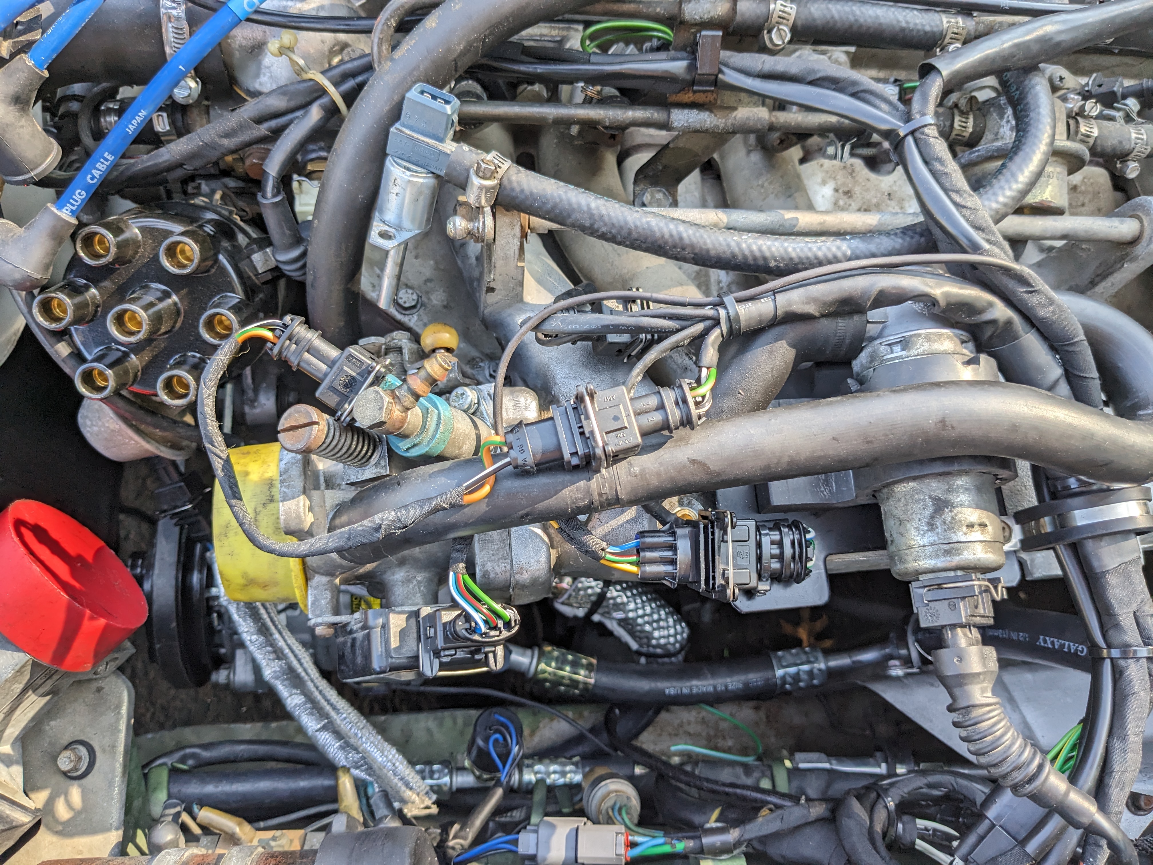
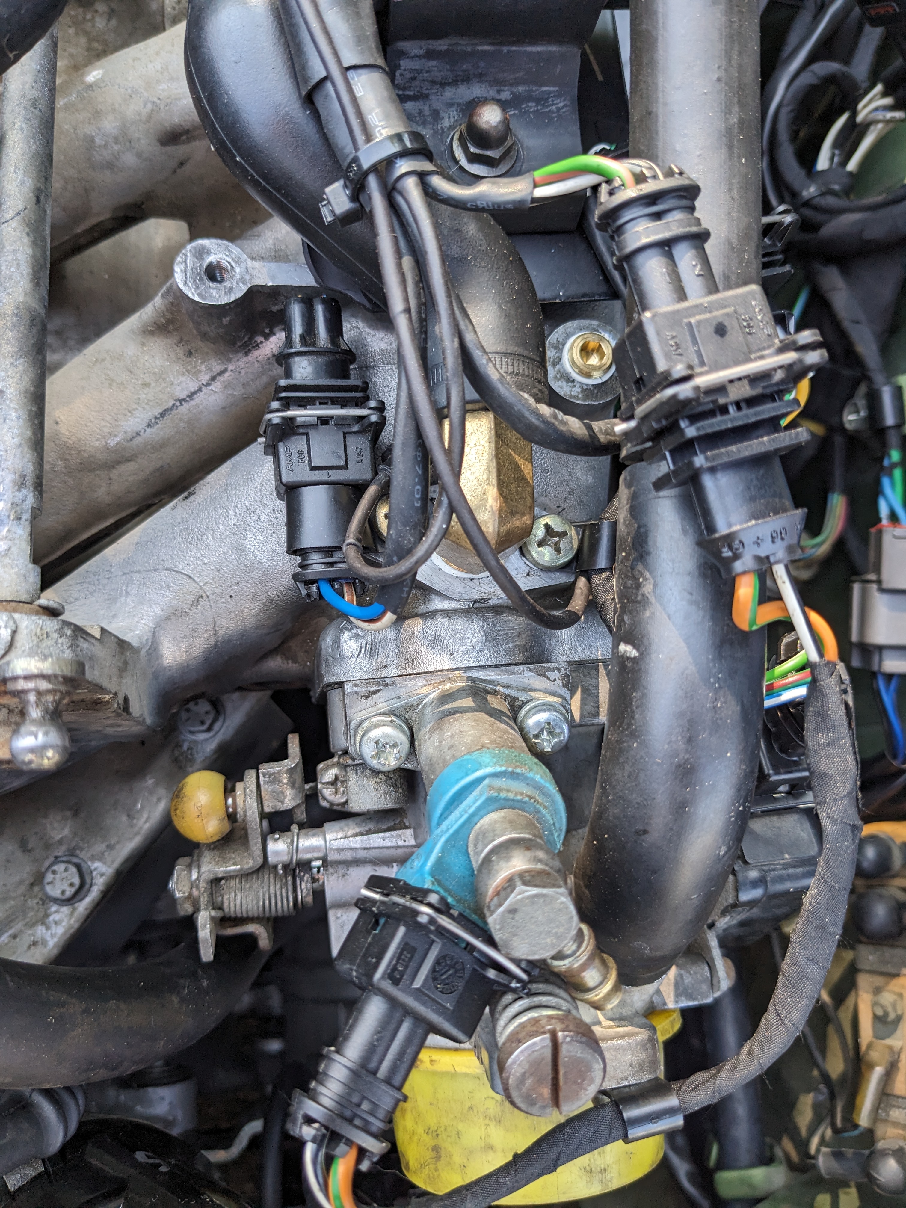
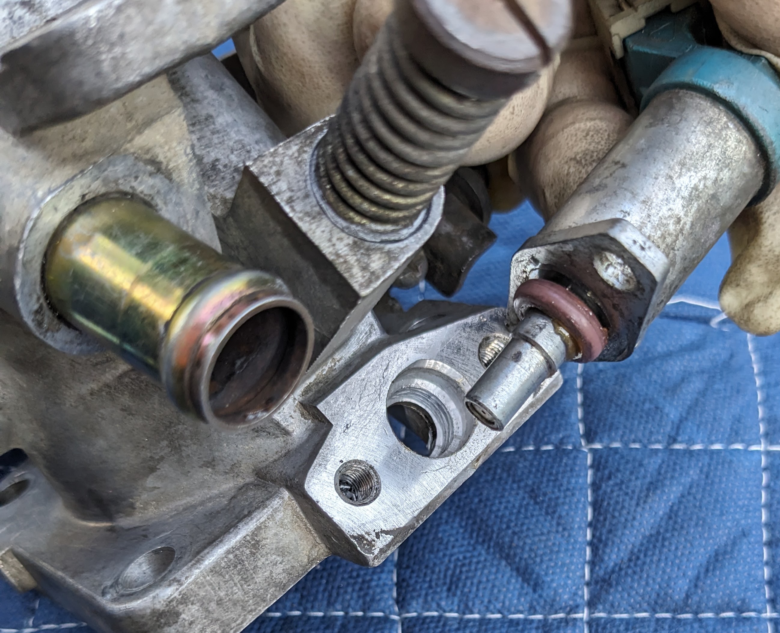
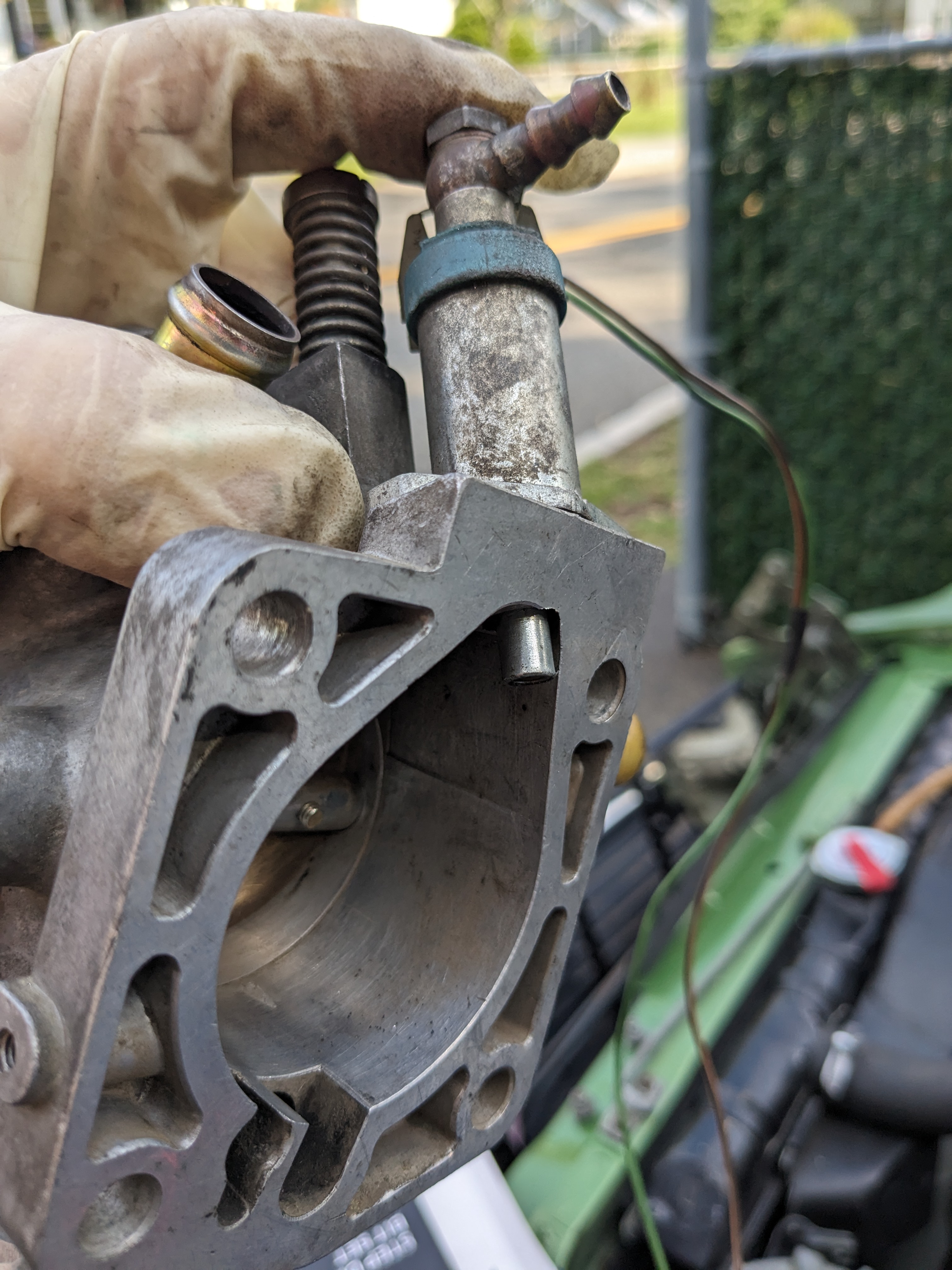
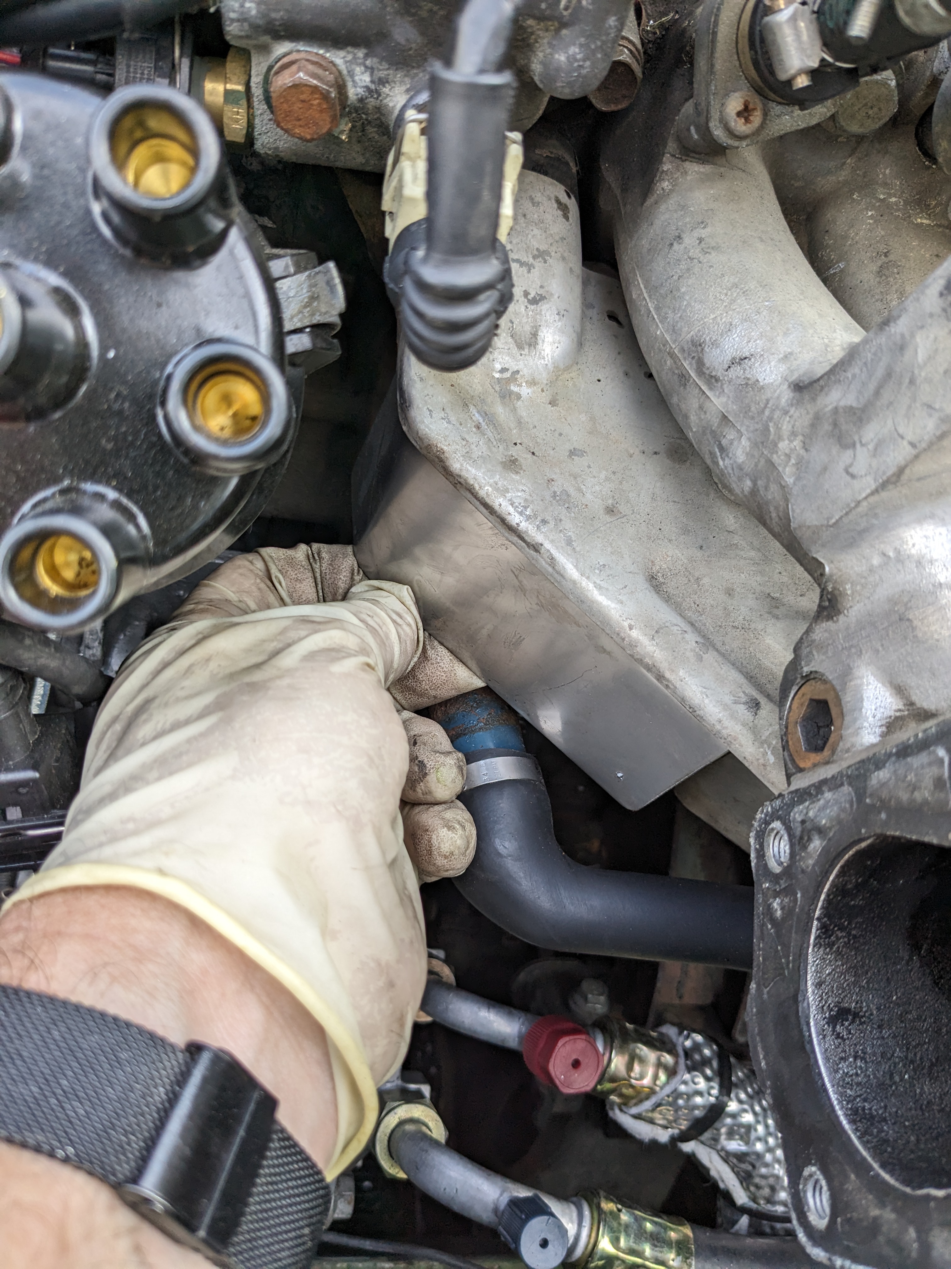
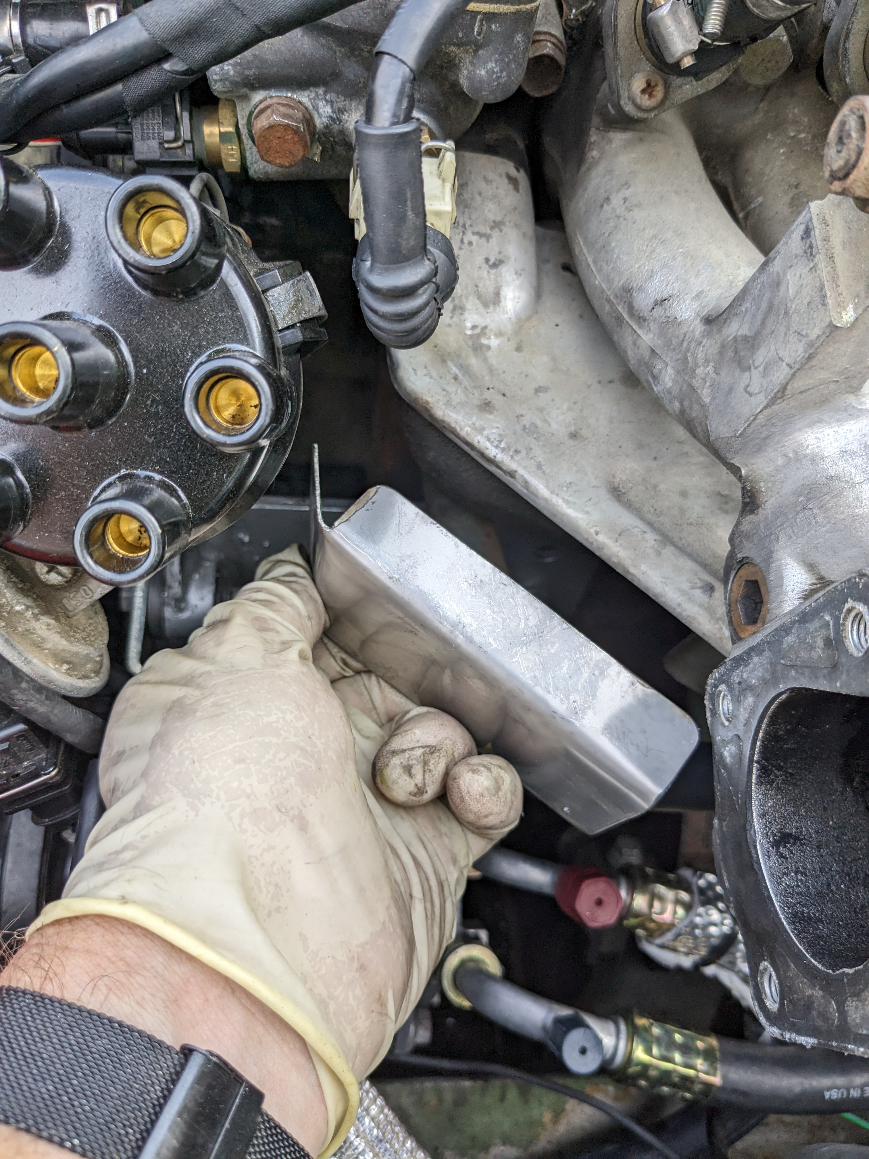
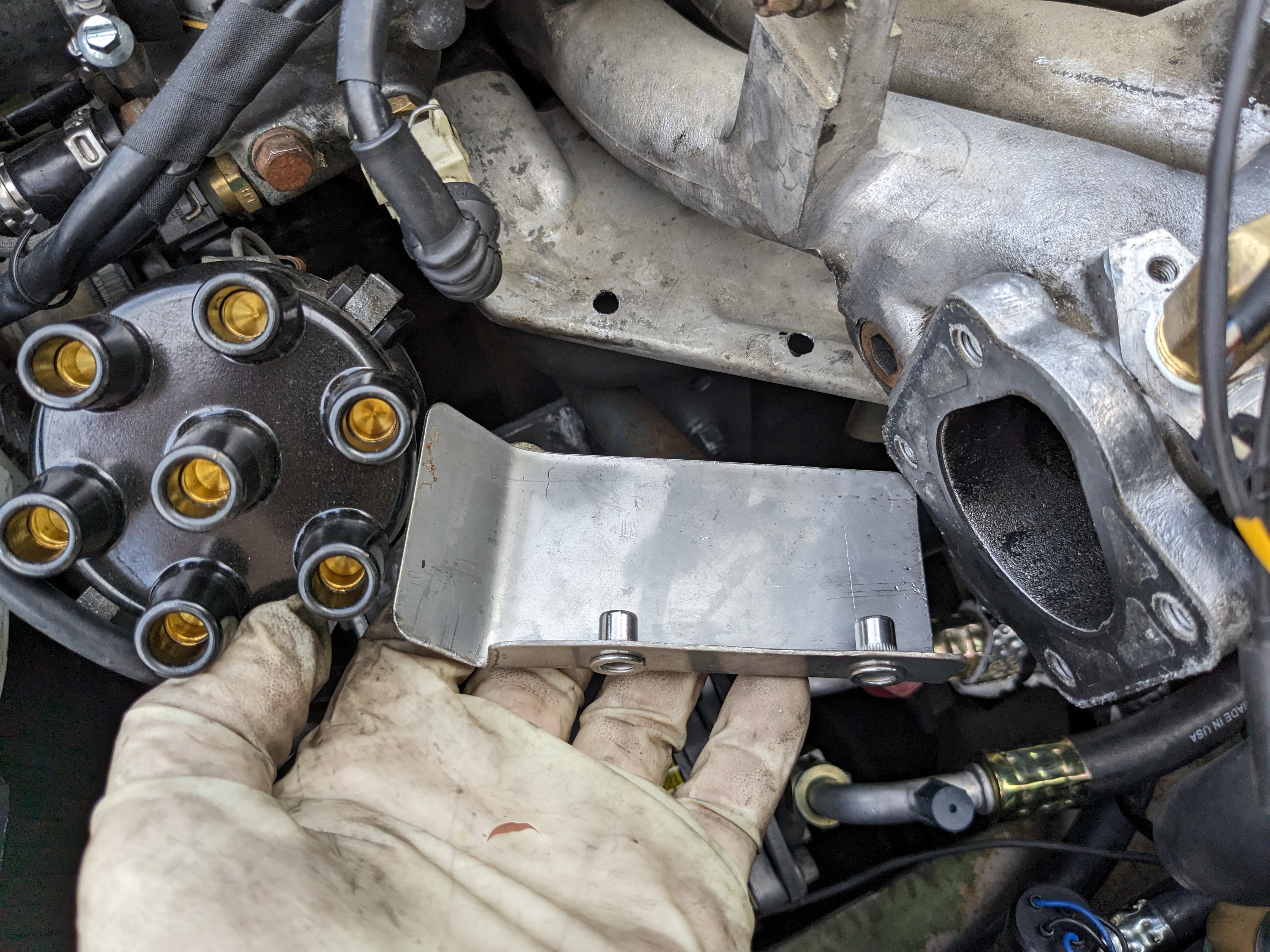
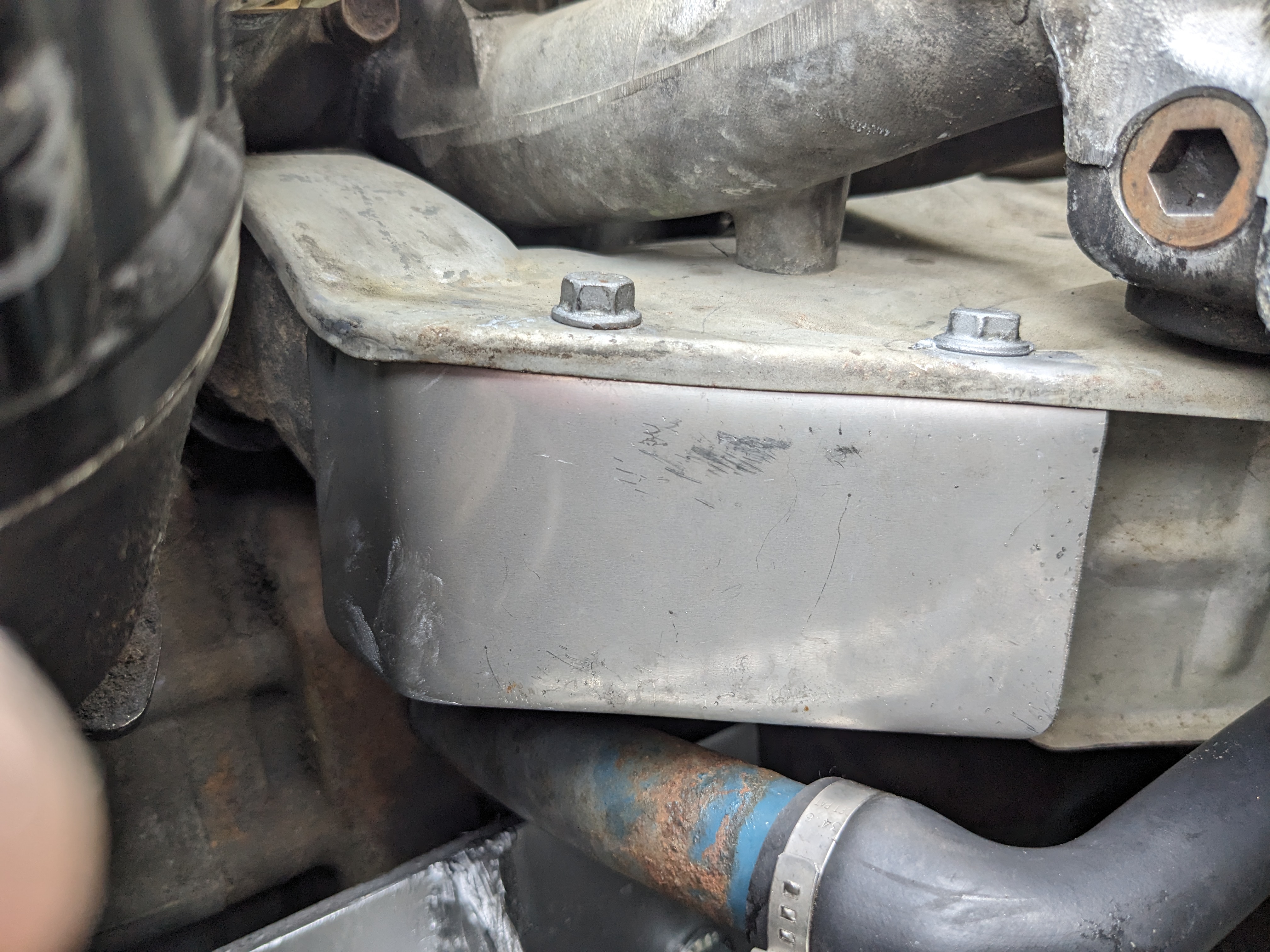
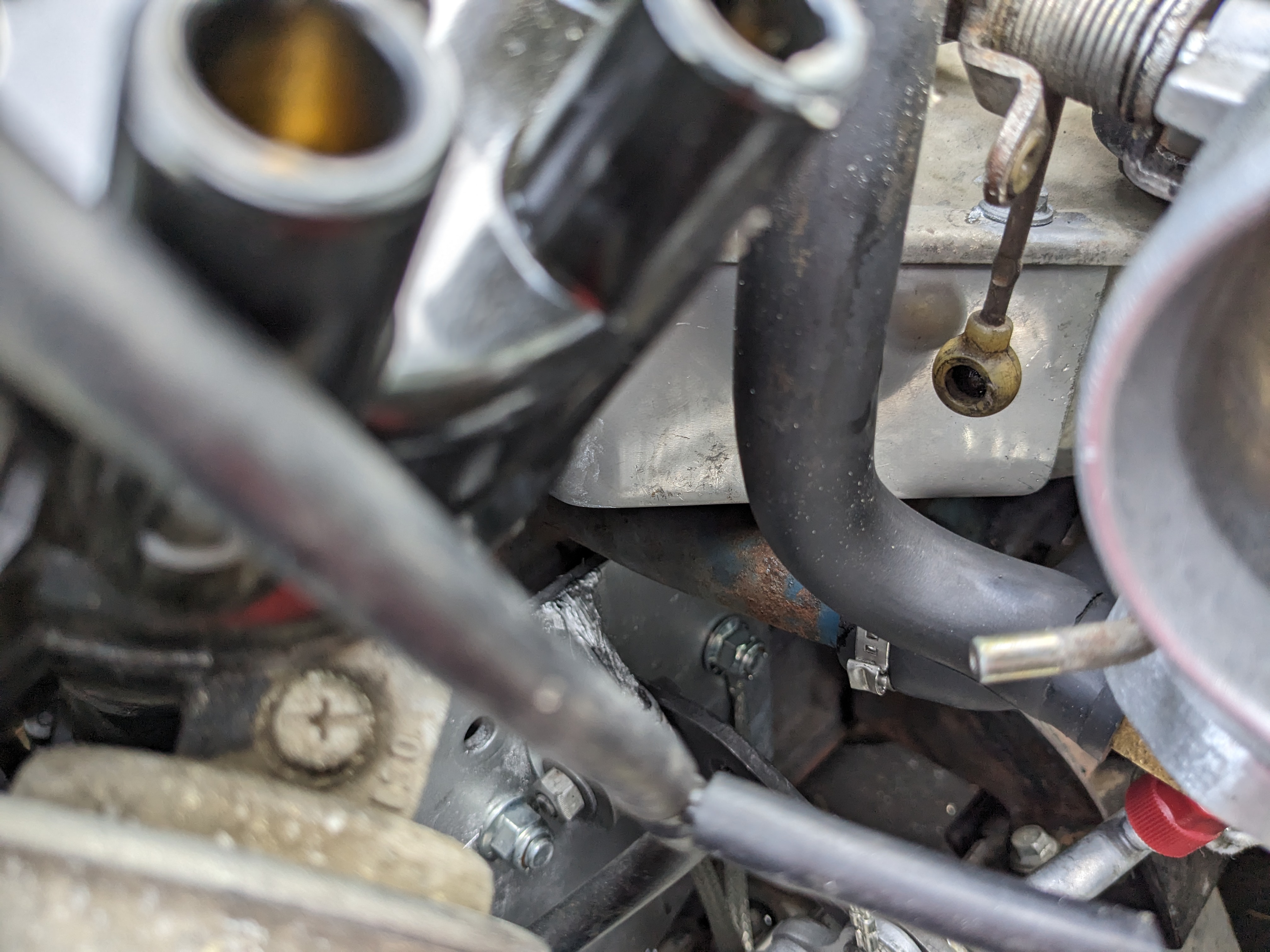
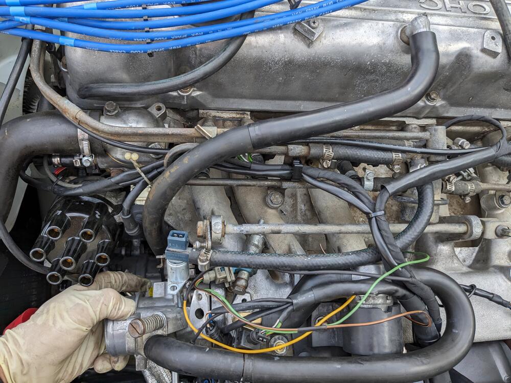
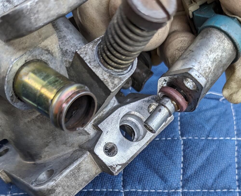
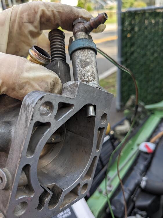
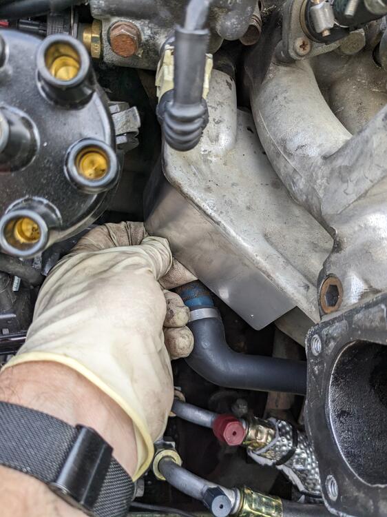
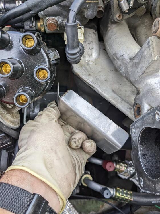
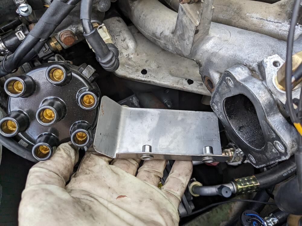
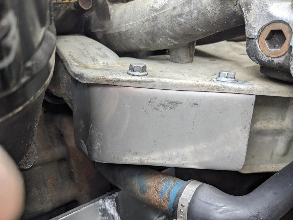
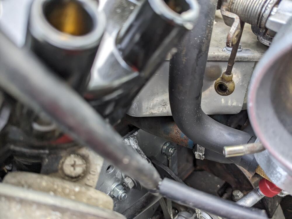
Only had about an hour after school today, so I worked fitting the CSV to the TB, and figuring out the VC vent/breather setup to the TB The Volvo CSV uses an o-ring to seat, rather than a gasket, so I countersunk the hole in the TB to 14mm, to allow an injector o-ring to seat snugly in there after that I worked on the vent/breather. I couldn't see a clean way to route the hose the long way around, as the factory layout runs, so I doglegged it & I'm running it down to the inside of the TB, clear of the linkage. EDIT - flame arrester is located inside straight section, not at upper elbow The thing about doing it this way, the #1 exhaust runner is exposed in that area, for whatever reason Nissan didn't make the pretty extensive heat shield come that far forwards. Since I don't want the vent hose to get crispy in the heat, I made a stainless steel additional shield, attached to the factory one. 5" length, about 2.75" deep, with a 3/4" flange adding SS M6 rivnuts fitted now the breather is protected somewhat
-
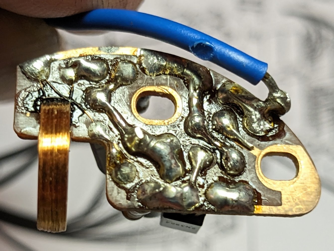
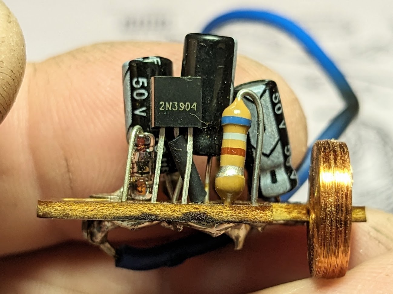
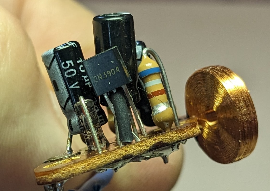
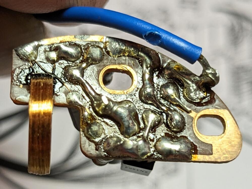
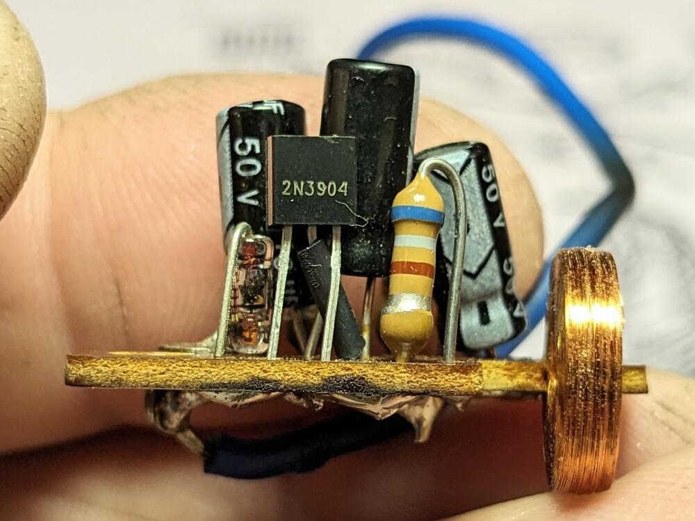
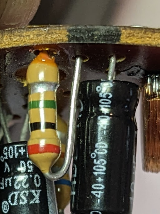
Thank you again for your invaluable input Ron. This is the 3rd resistor, next to the Transistor - looking up the 4 band, it appears to be 2M ohm, unless I'm reading the chart incorrectly Replaced the transistor (take 2) it's running now 🙂
-
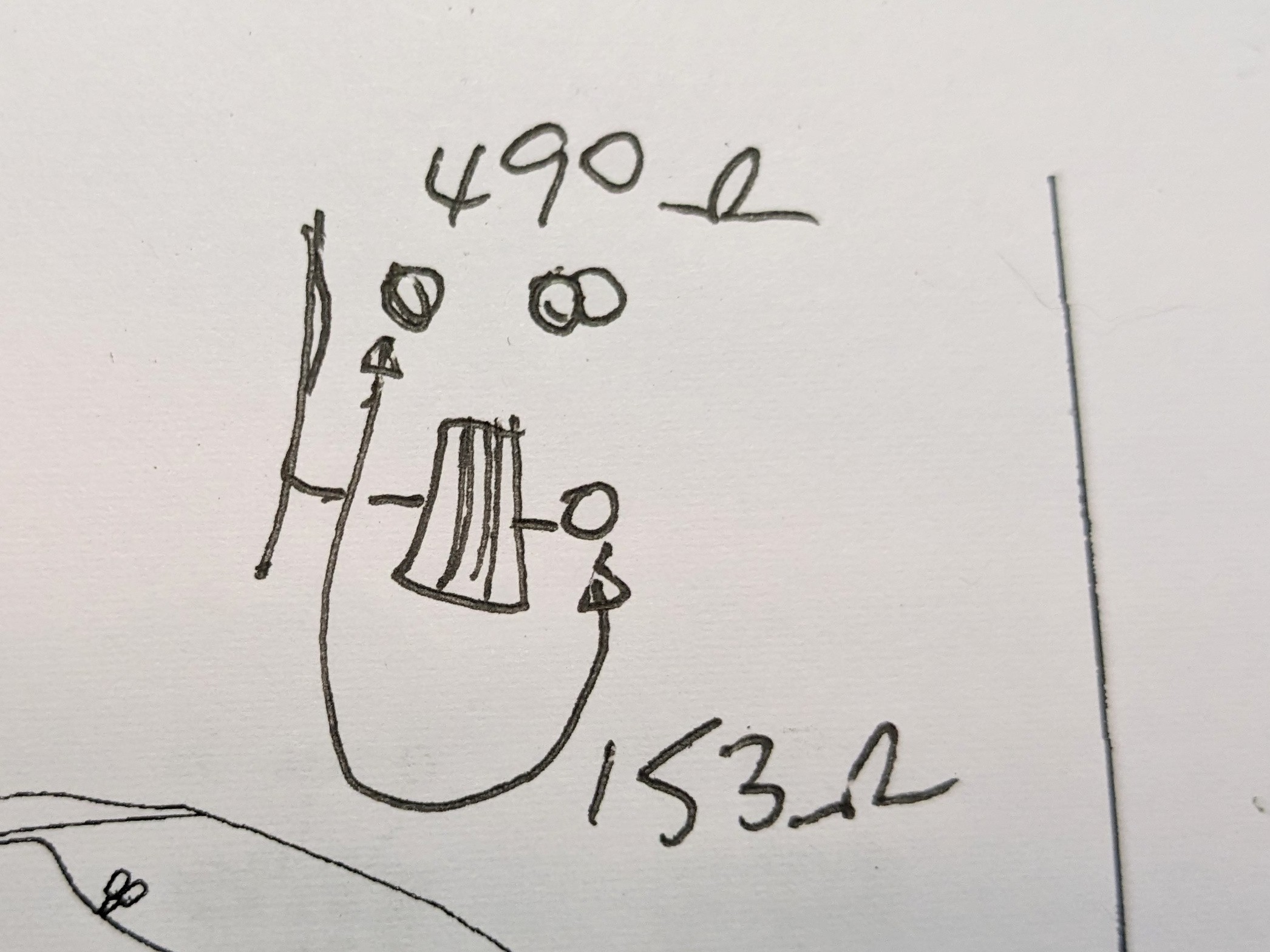
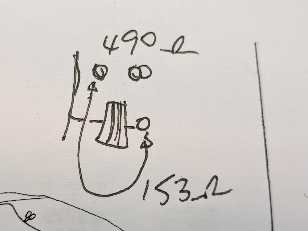
I did, and needless to say it didn't work. I'll change it out for a new one later. I was checking the various values of the other measurable items - it appears there are two 670ohm and one 2m ohm resistors. Zener still drops voltage to 4.4v using a 9v battery. Hopefully I didn't cook anything b sides perhaps the transistor by hooking it up incorrectly. My coil resistance values are the reverse of what you posted though?
-
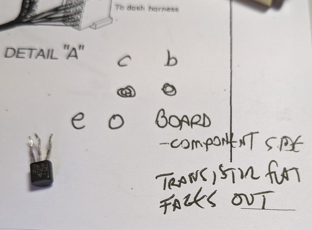
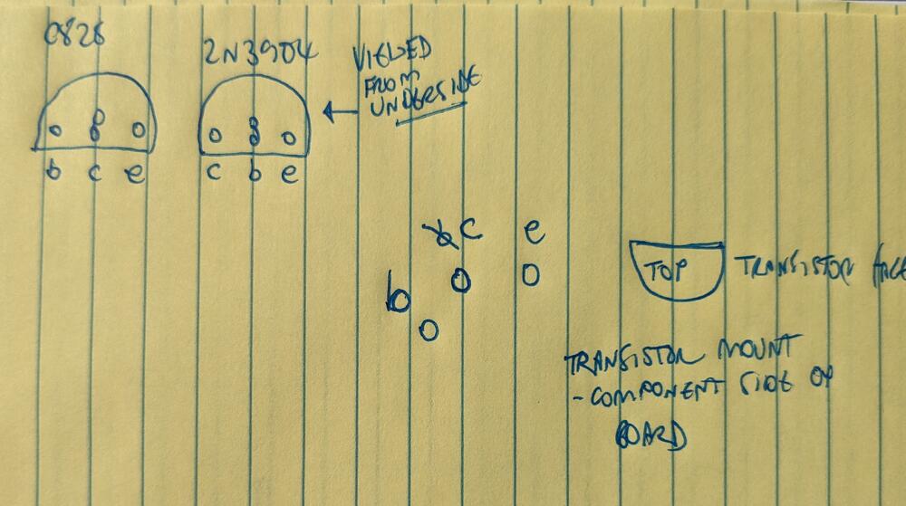
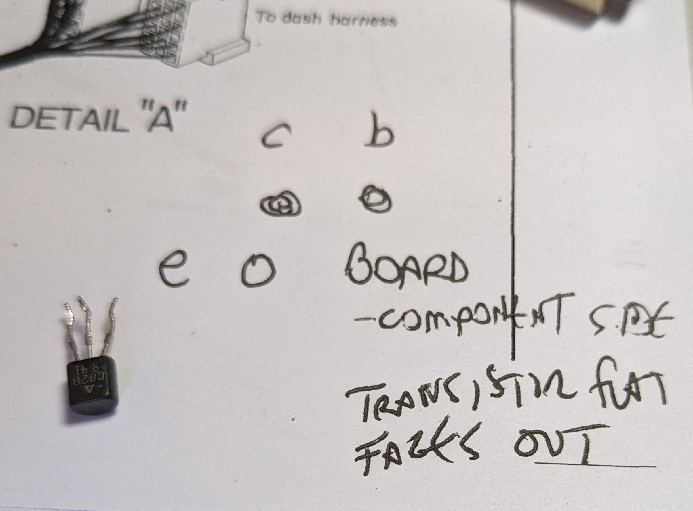
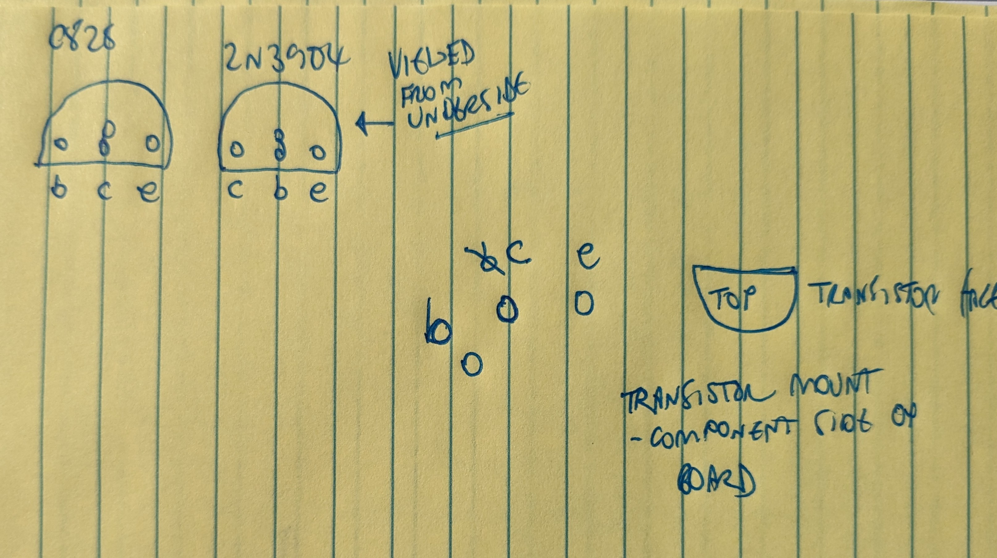
So, I replaced the transistor this morning - BUT - I got myself kerfuddled on leg orientation; between looking at the circuit board, transistor orientation, and the schematic from Ron I neglected to note the schematic says "view from underneath". As a result, I have the pin orientation al wrong What it needs to be