Namerow
Community Member
-
Joined
-
Last visited
Everything posted by Namerow
-
That's an interesting note re use of adhesive to bond in the dogleg-area repair (vs. the traditional weld-in approach). Care to comment further? Does the shop have experience to support the long-term effectiveness of an adhesive join for this type of repair? I assume that it's all about getting a perfectly clean and straight joint area that assures a not-too-thick adhesive layer. p.s. I'm not sure that flooding an adhesive-repaired area with an oil-based preservative like Rust Check is a good idea. Once again, does the shop have anyexperience with the long-term results of doing this?
-
FWIW, here's a bit more info on cyanoacrylate (CA) glue (c/o Wiki): "When added to baking soda (sodium bicarbonate), cyanoacrylate glue forms a hard, lightweight adhesive filler (baking soda is first used to fill a gap then the adhesive is dropped onto the baking soda). This works well with porous materials that the glue does not work well with alone. This method is sometimes used by aircraft modelers to assemble or repair polystyrene foam parts. It is also used to repair small nicks in the leading edge of composite propeller blades on light aircraft. The reaction between cyanoacrylate and baking soda is very exothermic (heat-producing) and also produces noxious vapors." " CA glue is also used in combination with sawdust (from a saw or sanding) to fill voids and cracks. These repair methods are used on piano soundboards, wood instruments, and wood furniture." And a big caution: " Applying cyanoacrylate to some natural materials such as cotton, leather or wool (cotton swabs, cotton balls, and certain yarns or fabrics) results in a powerful, rapid exothermic reaction. The heat released may cause serious burns,[23] ignite the cotton product, or release irritating white smoke. Material Safety Data Sheets for cyanoacrylate instruct users not to wear cotton or wool clothing, especially cotton gloves, when applying or handling cyanoacrylates.[24] " Fortunately, it appears that this caution doesn't apply to the natural fibres (if there are any) in our Z's door cards!
-
Chris: Just to be clear, what did you use to fix the areas around the clip holes: cyanoacrylate glue, f/g resin, or both?
-
Glad to see that this had a happy ending, Chris.
-
There are two different types of repairs required here: For the clip hole areas, why not approach this the same way that you would with a rust repair. That is, cut out the bad part and 'weld in' (glue) new material , cut to shape. Although it would definitely be easy, I'm not sure that a fibreglass repair is going to give the clip the right kind of surface to 'do its thing'. My idea would be to start with new, 1/8" masonite panel stock. Create a hole of the correct diameter (hole saw?), then use a small file to add the 'notch'. Now cut out the patch panel, complete with hole, and lay it over the door card so that the hole locations line up. Trace the outline onto the door card, then cut out that area. Now bond the patch panel into the cut-out area, using a fibreglass overlay on the 'back' surface. While I have not tried this myself (yet), I think it could work nicely. For the big tear, I agree that an f/g cloth-and-resin overlay will probably be the way to go. Here's an additional idea, though -- To temporarily bond the torn edges prior to applying the fibreglass, my notes include a comment from another CZCC member to the effect that a 'thin' cyanoacrylate glue used by model airplane hobbyists works well with the door card material. He referenced a brand called, 'Great Planes PRO CA' (packaged in the usual 1-oz eyedropper-style bottle). I'm not really sure how they manage to make this stuff thinner than plain old Crazy Glue, but it's promoted as having 'superior wicking action'. The label on the bottle says, 'Great for tight-fitting parts, tacking and CA hinges'. The Z owner in question said that he used it successfully to firm up 'mushy fibreboard around the holes' and reported that it resulted in an area that was 'super-hard and strong'. So: If you can figure out a way to press your torn edges together and flat, this glue might just do the trick. If you've got a spare piece of door card, maybe use that to experiment with first. Alternatively, try cracking a piece of masonite sheet and the use the glue to try to re-set the crack. Let me know if it works .
-
I'm not aware of any of the usual Z parts vendors (MSA, Rock Auto, etc.) offering an aftermarket harmonic balancer. Who's your source?
-
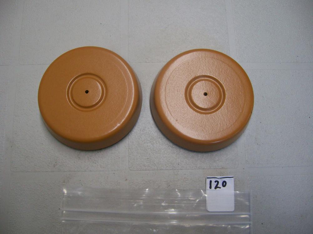
I'm in the middle of performing the same fix on my regulators, too. The match of the outside dimensions (outside diameter, thickness) between the PA tarp grommets and the Nissan 'cone washers' is remarkable. Whoever spotted these as a replacement deserves a medal for 'thinking outside the box'. It will be interesting to see how well this works. The Nissan 'cone washer' is made from a flexible plastic and has a fairly thin cross-section, meaning that it's pretty compliant as it slides along the regulator arm's and can compensate for a degree of wobble in the roller (of course, this also means that it tears and then falls off). It looks like it was intended to act like a really soft thrust washer -- creates a little bit of pre-load and takes up the slop in what needs to be a fairly high-clearance assembly. The PA tarp washer is made from hard plastic, so it has no 'give'. It will be able to wobble on the pin shaft, but only because it's a sloppy fit. It will serve to fill the clearance gap, but it won't act like an axial spring. I'm not too worried about it jamming or sticking, but I expect that the action may feel a bit different. Won't know until everything's installed in the car.
-
Some recommend laying down 1"-wide masking tape around all edges of a panel before applying the stripper. This keeps the stripper from finding its way into any edge seams. Afterwards, they remove the tape and use mechanical means to remove the paint along the panel edges. Hadn't heard the tip about using paint thinner to neutralize/remove residue. There was a good review and how-to of paint stripping that appeared in a British resto-mag a couple of years back. Key points made: They found a noticeable variation in effectiveness across the 7 or 8 brands tested. The best worked in a single application and in a matter of a hour or so. The lest effective had to be left overnight and required a second application. Effectiveness was improved by scoring the paint with a dull razor blade before applying the stripper. Cross-hatch, one-inch spacings. Try not to score the underlying metal. Effectiveness was also improved by laying a sheet of poly over the panel after the stripper had been applied. They also noted that, in Britain (maybe the US too), environmental issues had forced a change in stripper formulations ~ 10 years ago, so they're not as aggressive as in days gone by.
-
Nice job. Do you think that the plastic material used for your 3D printer is going to make your repro choke and throttle-lever knobs more (or less) robust than the breakage-prone originals? Can you post a close-up of those two pieces?
-
I have it and it's an interesting read. Done in comic book style, complete with caption 'bubbles' when the characters speak. The artwork is quite good. Sometimes overlaid with b&w photos. I think it provides a nice treatment of the human element in both the Z's creation and development program, as well as the entry of Nissan (under the 'Datsun' brand) into the North American marketplace. The book really brings a lot of the Japan-based Z design/development teams' names into the foreground (whereas we in North America traditionally tend to hear mostly about Mr. K's USA-based exploits). The graphics may make you think that it's a kind of childish treatment of the history, but it's not. Lots of interesting parts of the 'backstory' emerge. As a Canadian, I particularly enjoyed the coverage of the cold-weather development work that was done with a set of pre-production Z's out of the Brasso Datsun (sorry, 'Nissan') dealership in Calgary, Alberta. Bonus: If you buy it, this will probably become the only book in your library that reads from back to front.
-
We all know that a lot of the rubber* parts on our 40-year-old cars have hardened with age. Sometimes this leads to cracking, but it seems to depend on the application. (* Caveat: For many of these parts, I'm not really sure that they are made of rubber... as opposed to something man-made). Then there's the issue of exposure oil. Also potentially not good for rubber. Turning to the flexible core of the L-series engine's harmonic balancer, it would certainly be a candidate for age-related problems, and -- for an engine with 'a history' -- it might even have been exposed for years to a caked-on layer of engine oil and dirt. So here's my question: Ignoring racing applications, has anyone ever heard of a an L-series harmonic balancer causing problems? Or failing, for that matter? Or is that flexible core made from a synthetic material that resists aging and chemicals? Bottom line: Is this a part that's a candidate for preventative-maintenance replacement, or can it be safely ignored for street-only duty?
-
I also used the SEM Bumper-Bite bumper repair material. Not my favourite filler, by any means -- I found it very difficult to work with. Not all that flexible either. The Dupli-Colour bediner paint dries with a kind of 'dry rubbery' feel, but it coats more like paint than like the 'vinyl dye' stuff that I used for my hard and soft trim pieces. I don't think it would fill hairline cracks successfully, but that's based on memory. You could always experiment on a test piece and judge for yourself. Try this: apply some of the SEM bumper repair filler on a piece of cardboard, let it set, sand a smooth patch, then bend the cardboard to crack the filler, then try the Dupli-Colour bedliner spray to how good a job it does of masking the crack. If you don't like the result, I think I would be inclined to fill those cracks with glazing putty and then spray on the bedliner as a top coat.
-
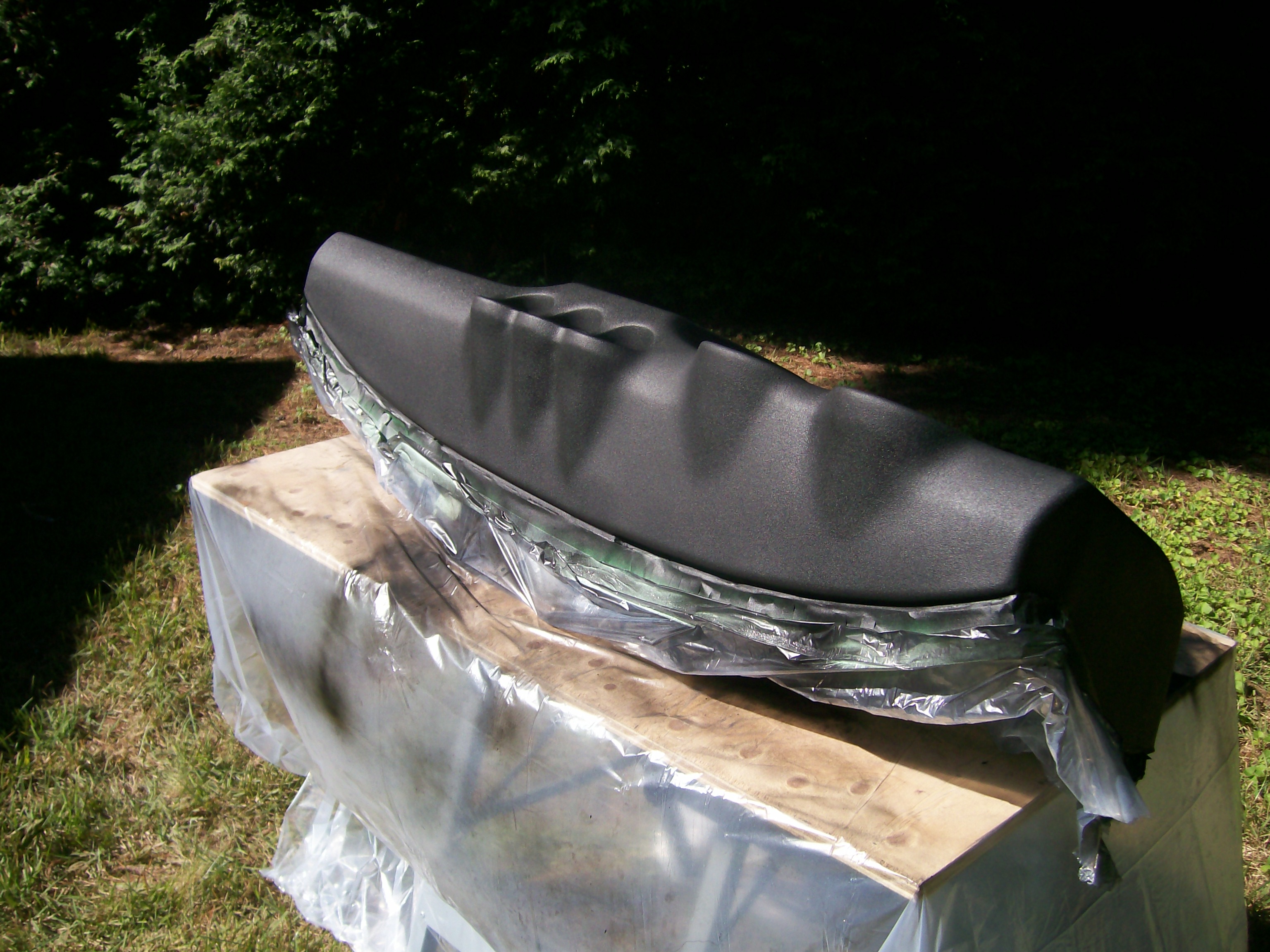
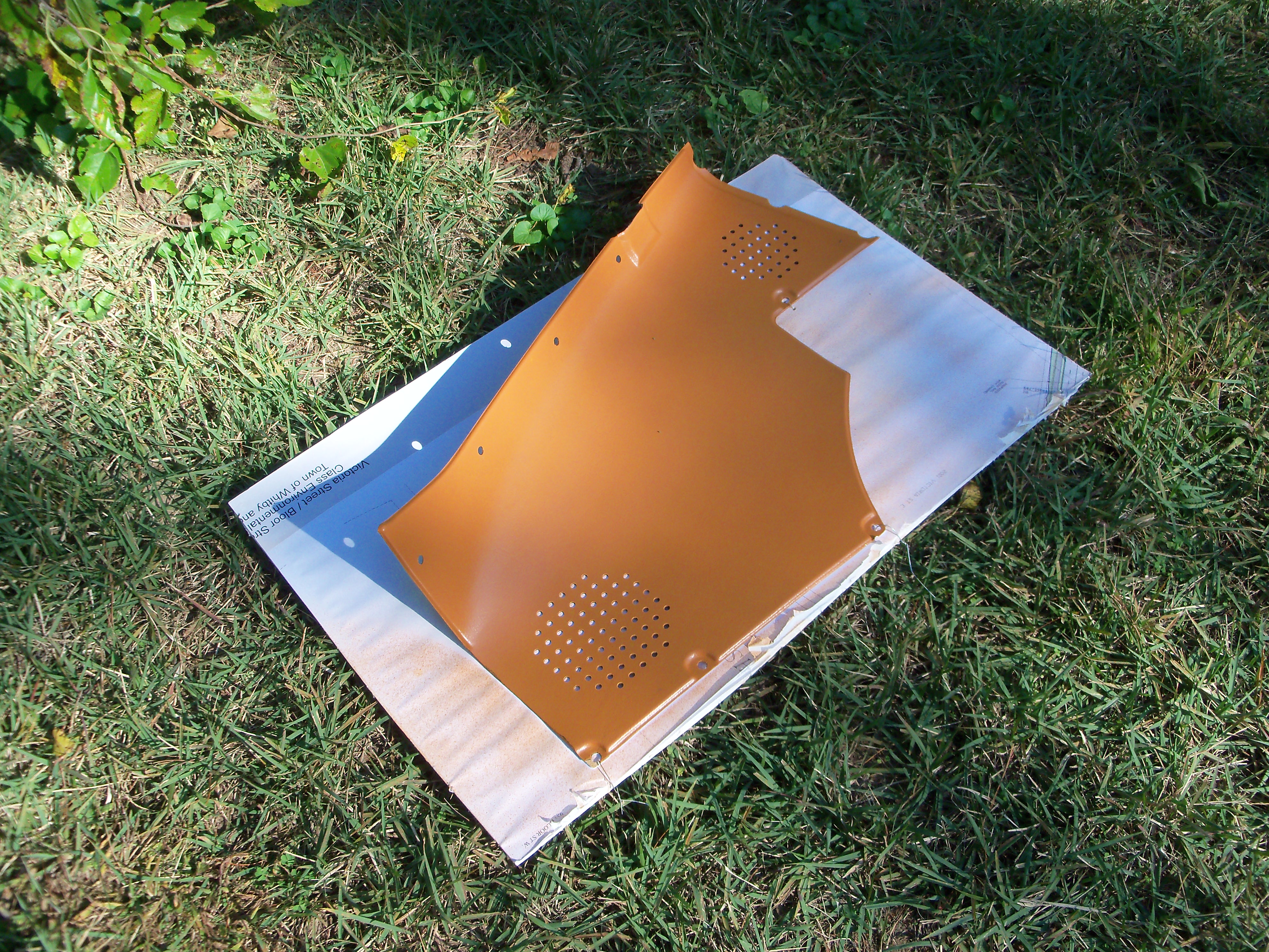
That looks very promising. I experimented with thin, flexible vinyl (stretchy fabric backing) for my dash project before deciding to go with textured paint. I found that the vinyl simply did not have enough formability to contour around and into the gauge recesses -- even in bright sunlight and assisted with a heat gun (see photo). Even if I'd been able to get it to form down fully into the recesses, it looked like there were going to be major wrinkles happening around the outsides of the pods. The Z dash has some very challenging contours! BTW, the vinyl I tried was the thinnest fabric-backed material I could find at the local fabric store. I did actually find a manufacturer that makes a textured vinyl with the exact 'haircell' design used by Nissan in the Z. It was 3-mil thickness IIRC. The manufacturer wouldn't answer my emails, so I gave up. That said, these new commercially-available automotive wraps are also only mils in thickness and they seem to have the ability to form around significant contour changes successfully. Not sure whether wrinkling around the gauge pods isn't still going to be a problem, though. And if my dash repair starts to show cracks (it hasn't, 2 years later), I think this stuff might be my next strategy. If you try it, be sure to post some pictures of the results.

-
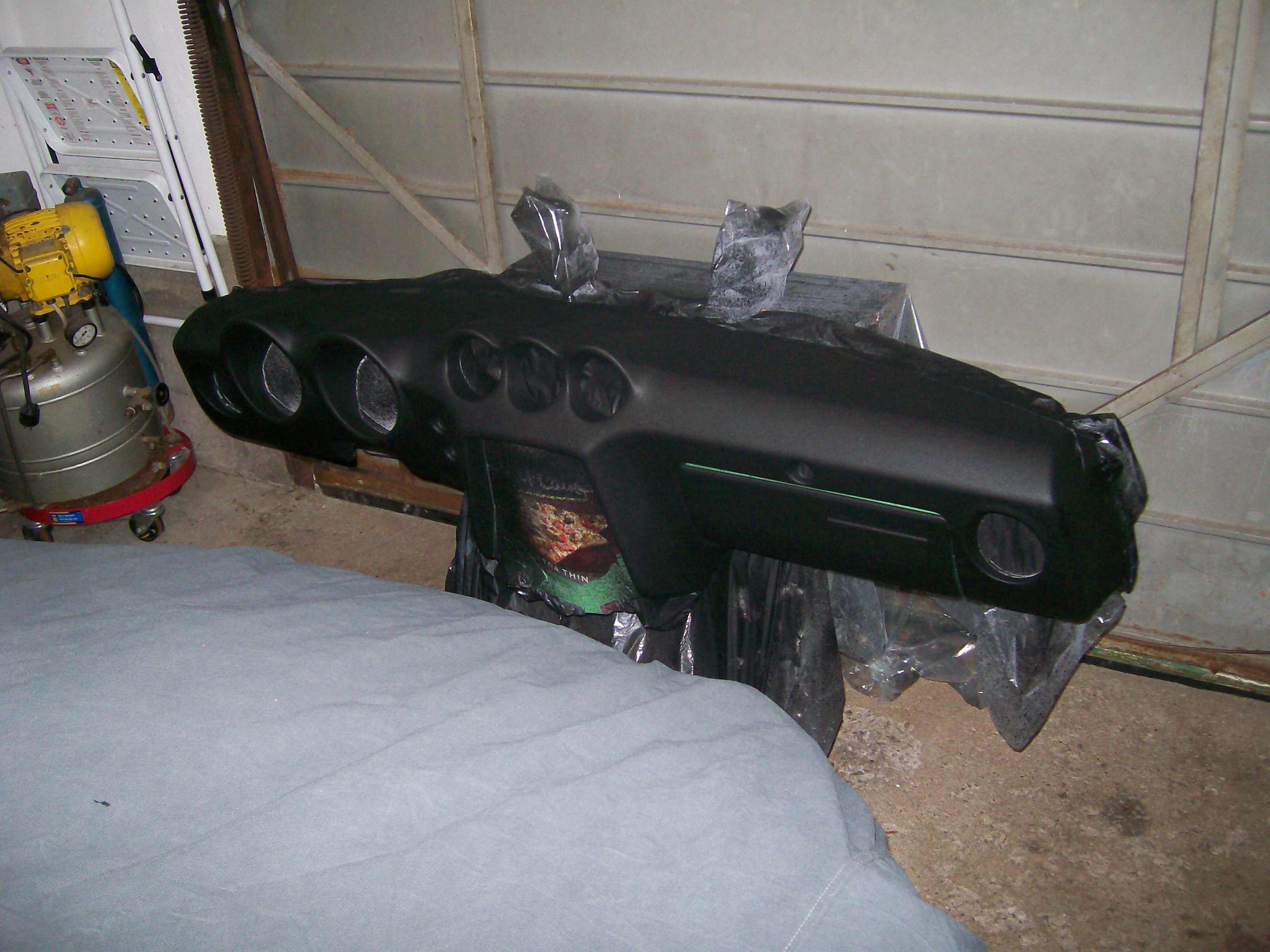
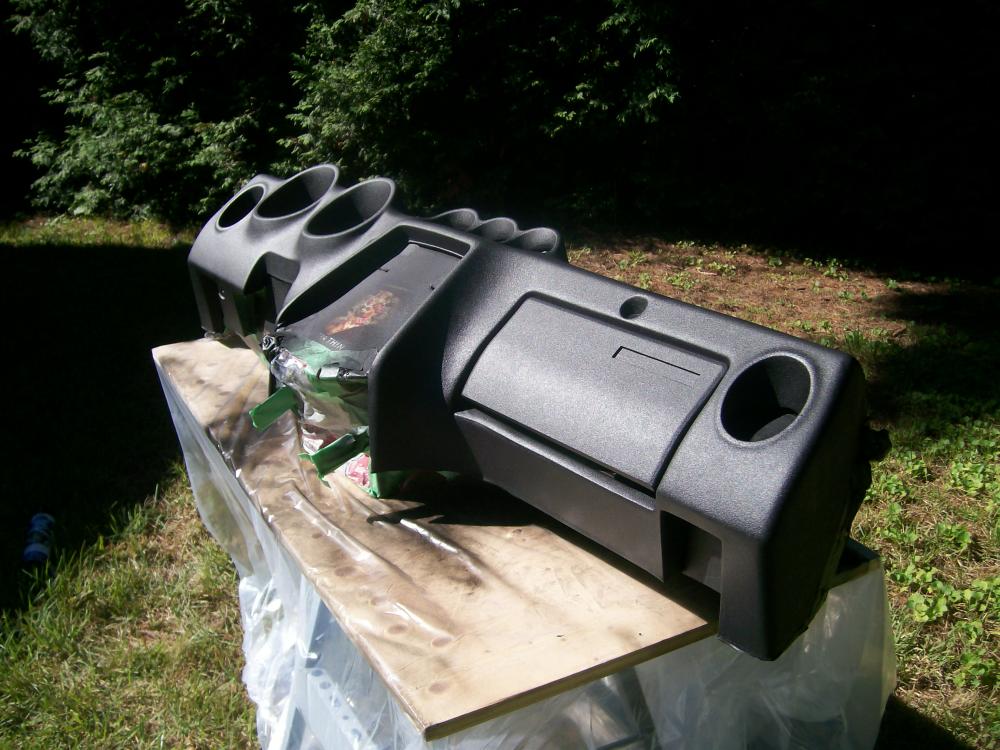
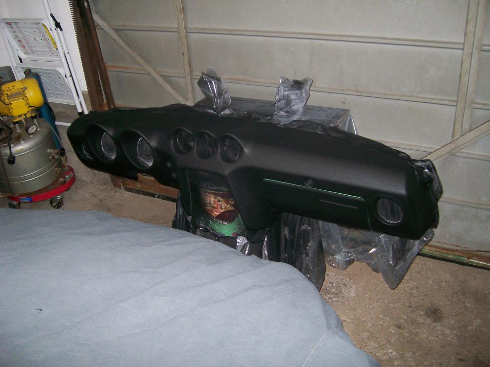
Re application tips: I refinished my dash with similar results. I'm happy with the outcome, even if the texture I ended up with isn't the same as the factory 'haircell'. Based on the pictures Chris has posted, the final appearance I got looks to be about the same. In my case, though, I used Dupli-Color's bedliner paint rather than the SEM texture product. I found one curious thing during the spray application that may help others who try this repair-and-paint process with their own dash: The bedliner/textured paint tends to start 'spitting' out of the spray can, no matter how much you keep it shook up nor how well you keep the spray tip clear. The result is 'blobs' of wet paint that appear to have ruined the finish. Out of desperation, I tried lightly touching one of those surface blobs with my fingertip to see if maybe it could be smoothed out. The result surprised me. Just that light touch settled the blob right out. I don't understand the mechanics, but the action was self-evident. I ended up making this a standard part of my spray-application routine with this kind of paint. The end result (three coats) was a nice uniform finish, with no 'blob residue' in evidence. I covered the bedliner paint with a finish coat of SEM's 'Landau Black' to make the surface feel a little harder/smoother to the touch (the bedliner paint feels a little 'grippy'). If you decide to try one of these texturized paints, I recommend you experiment on a big piece of cardboard before you start on the actual dash. In my case, I had a spare glovebox lid to play with. You may also want to experiment with the different texture paints that are available to which one you like the best. A difficult aspect of the paint application is getting coverage inside the instrument pods without accidentally over-applying to the surrounding areas. Takes some practice and forethought to avoid problems. BTW, I found that my B&D 'Workmate' folding bench was perfect for mounting the dash during both the crack-filling and the paint-application steps (see picture #3). Note the big C-clamps used to clamp the sheet-metal armature of the dash to the top of the bench.

-
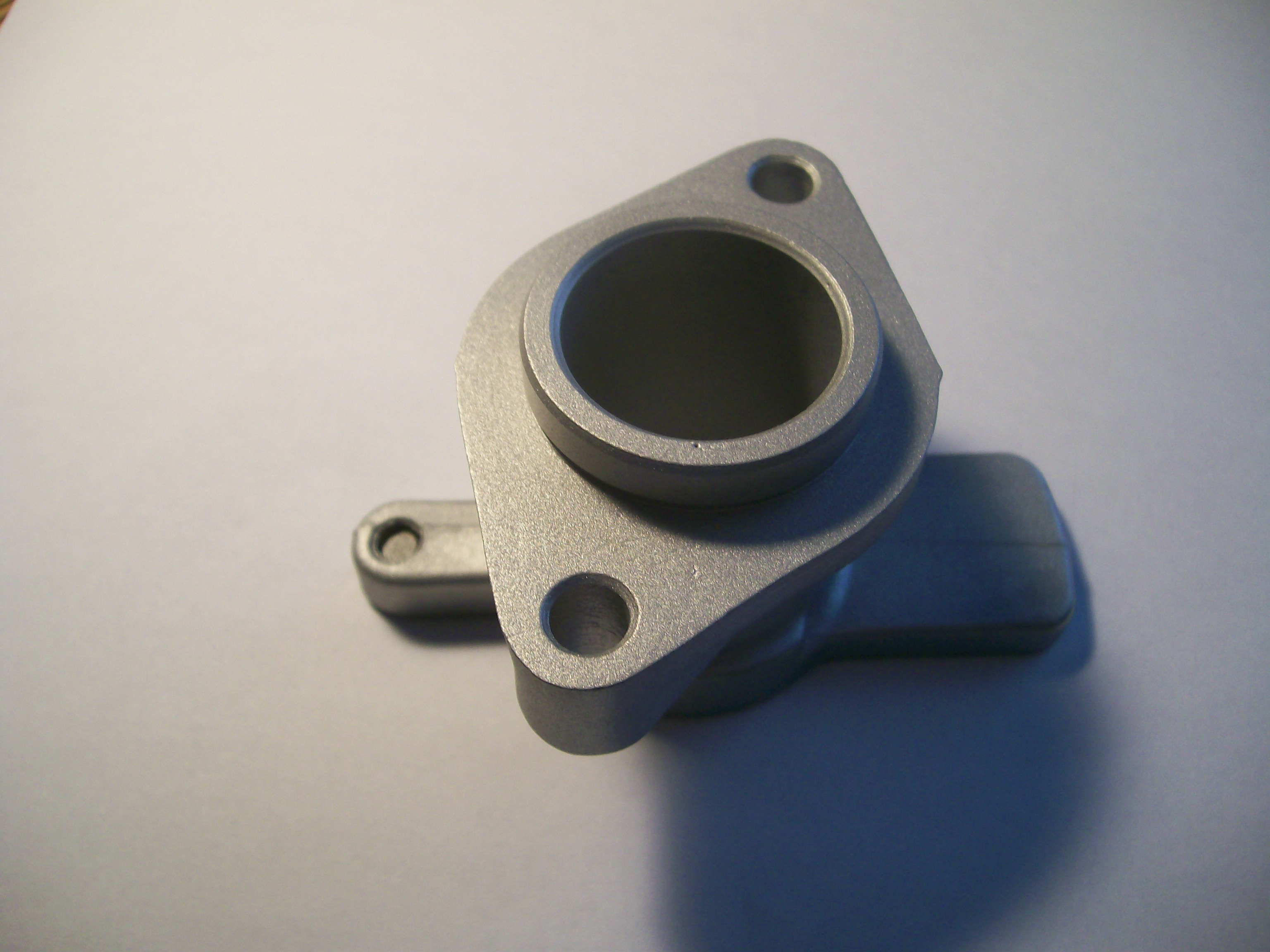
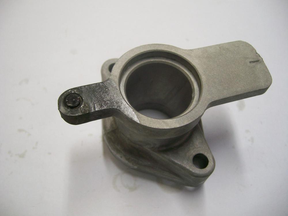
Sorry, but those are pix of the same part. Just turned upside down in the 'after' shot. No way I was going to leave this part in this solution any longer than I did. Too much action happening on the aluminum surfaces and I didn't want to damage the machine bore. In any case, my experiment wasn't really about fixing this part. Instead, I wanted to see whether this technique had any promise for getting the snapped-off manifold stud out of my car's cylinder head. The distributor casting was just a guinea pig. I just had lunch with my my friend the chemical engineering prof earlier this week, but we talked mostly about my zinc electroplating set-up and I forgot to ask about this other process. If I pick up any insights in a future conversation, I'll let you know.
-
and once again we head down the rabbit hole...
-
I had high hopes for this treatment but -- like many things that appear too good to be true -- I can now report that, after trying it out, this whole thing is 100% bogus. My test piece was a spare distributor base casting, complete with the remnants of the snapped-off locking screw. I bought a small can of alum off the grocery store's cooking spices shelf and then dumped it into a small saucepan full of water. After bringing the water up to just below boiling temperature, I dropped the casting in to see what would happen. There was a lot of bubbling action, although it all seemed to be coming off the aluminum surfaces rather than from the area of the snapped-off screw. After watching this for about a minute, I started to get concerned that the process was attacking the wrong metal (i.e. the aluminum, and not the steel). I re-jigged the casting so that only the 'ear' with the screw shank was immersed in the water, and then let things go for about 20 minutes. There was still no sign of anything really important happening around the steel screw. After the twenty minutes were up, I pulled the part out of the water to inspect it more closely. As you'll see from the 'before' and 'after' pictures below, my suspicions were correct. The aluminum had been eroded (you can see the etching lines from where the water surface was located). The exposed surfaces of the screw shank were darkened, but that's about it. I still had hopes that maybe the chemical action had attacked the corrosion between the screw threads and the casting threads, so I took it down to my workbench to see if the screw was perhaps now loose (or, at least, not as frozen as before). Nothing doing. It still wouldn't budge, and now I'm back to having to drill it out and re-tap the hole. In addition, the 20 minutes of full immersion had 'pickled' the rest of the aluminum casting's surface, making it darker and -- well -- not as nice as it looked at the start, fresh out of the blasting cabinet. End result: Perfect alloy casting is now not so perfect any more, and the snapped-off screw is still firmly stuck in place. Conclusion: Don't waste your time on this 'miracle cure'. It doesn't work and it will eat your aluminum parts.

-
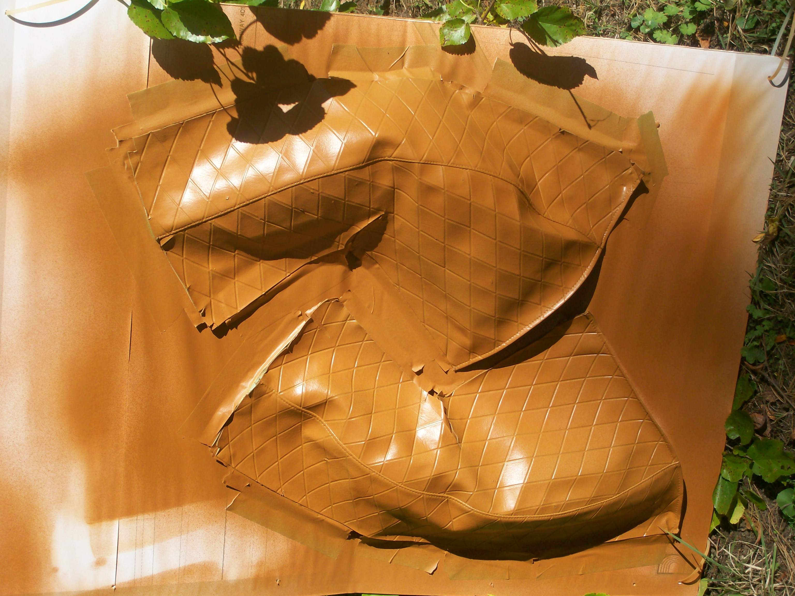
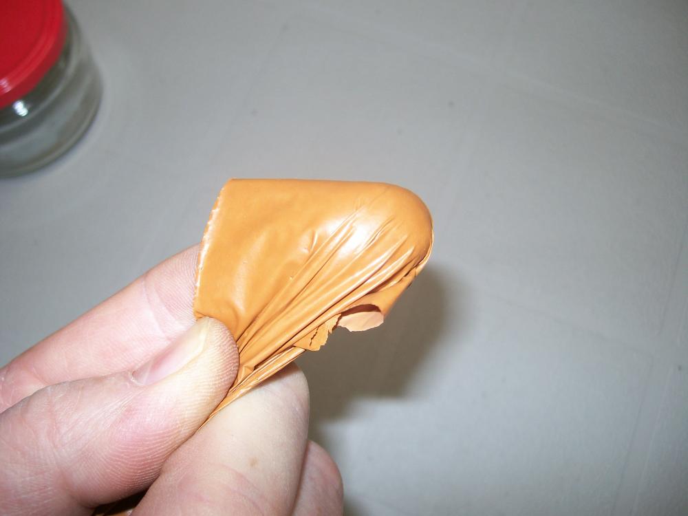
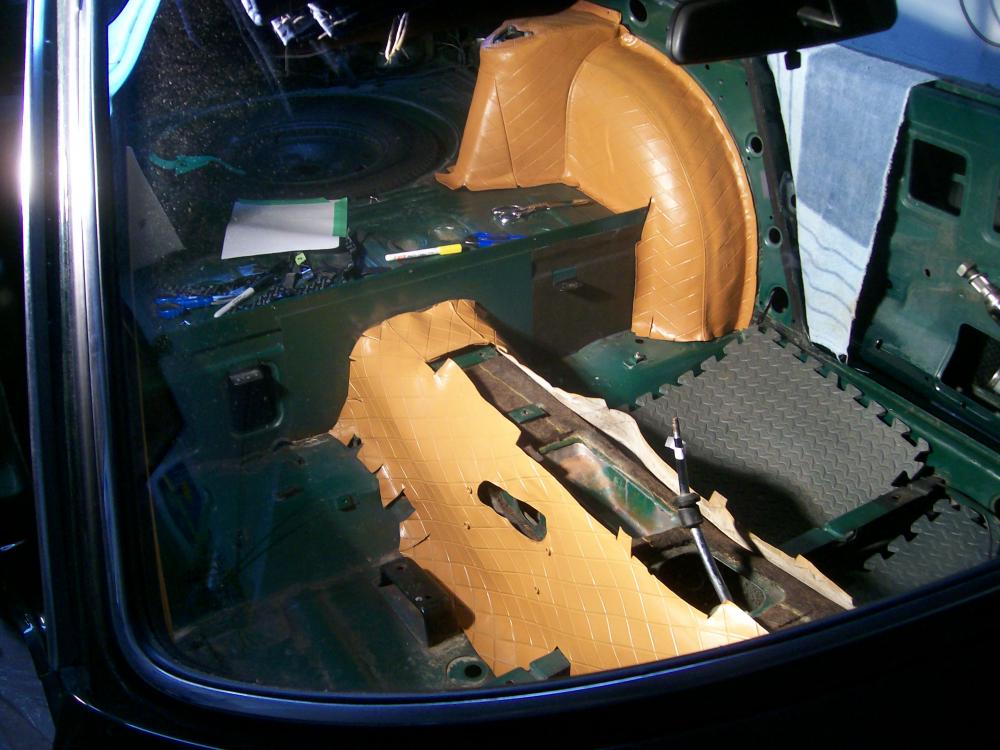
Hi Chris: You've seen my Z's interior panels, treated with spray-on 'vinyl dye' that I sourced from Parasol in Toronto. Here's a picture (#1 of 5) I took of some oversprayed material that I peeled off a test surface. It should give everyone a sense of the thickness and consistency of the 'dye' material after it's cured. As you can see, it's not really a dye at all, but more like a flexible-vinyl coating. I have zero concerns about its adhesion to the hard plastic parts, and the coverage (butterscotch dye applied over black plastic) was excellent. A bonus was that Parasol were able to color-match the dye to my new (Banzai Motorsports) butterscotch seat covers (thank you, Mike). The soft vinyl parts were a bit trickier, due to the challenges of fully removing years of ArmorAll applications. It took a lot of scrubbing with a scotchbrite pad and SEM's vinyl cleaner product to get these pieces ready for painting. For the most part, I'm happy with the end result (once again, butterscotch applied over black) and I do not foresee any application-related lifting or peeling problems. I would not recommend vinyl dye treatment for seat covers, though. That's just asking for trouble. As for resistance to scuffing and scraping (esp. in the cargo area), I think the first picture tells the story (i.e. it probably will tear if it's abused).


-
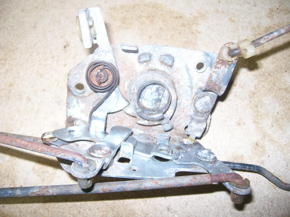
The Latch works on a kind of ratcheting principle. Hard to visualize until you play with one that's been removed from the door. If you get it cocked into the 'latched' position, you should be able to get it to release by pulling on the inside door handle. The hidden workings of the Lock (i.e. on the other side of door, per your photo) can get pretty gummed up and rusty, so getting lubricant in there is a lot more helpful than trying to oil from the outside (which only addresses one of the many moving parts in the assembly).
-
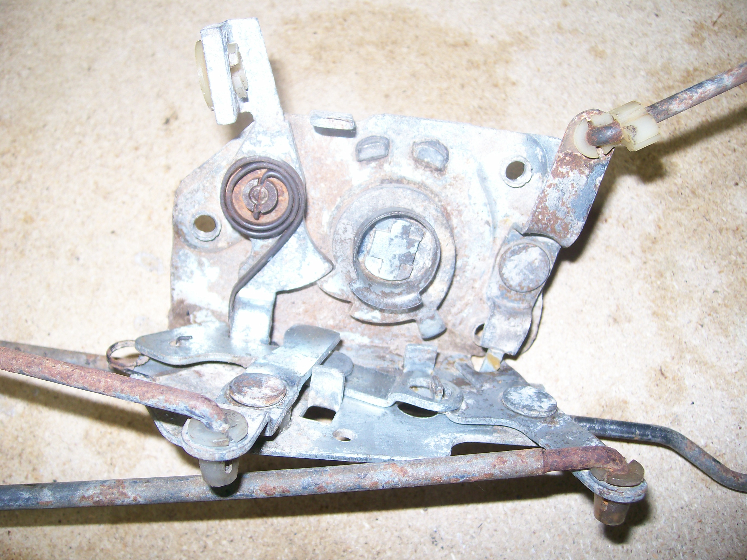
That is the 'Assy-Lock Door LH' (Nissan PN 80501-E4100). You can't see most of it in the photo, because it's on the other side of the door panel. The part of the Lock Assy that you can see from the outside (per your photo) is sometimes referred to as the Latch. The little plate below it is called a Dovetail. Shouldn't be hard to find a replacement Lock Assy. Unfortunately, they come equipped with lock/latch control rods that are very hard to disassemble from the actual Lock unit, so you'll probably need to buy one as a complete unit. Z Car Source of of Arizona offer them for about $225 (used). I suspect that somebody on this site might be willing to offer you one for a lot less. Yours can probably be fixed, though. In fact, it may not need fixing at all. Instead, your Striker Plate (the part on the door jamb) may be mis-aligned, in which case the door won't latch closed properly. There are some very good write-ups on this site for how to carry out the lock/latch/striker alignment process. The best one, IIRC, was done by our late friend EScanlon. In addition, I see that at least one of the two engagement lobes on your latch has lost its rubber cover. It's been documented by others that this apparently minor reduction to the outside dimensions of the lobe can cause the door to not latch properly. You can buy new rubber covers inexpensively from Steve at www.240zrubberparts.com. I also see that someone has replaced one of the mounting screws for your Lock assembly with a slot-head screw. It should, instead, be a stubby countersunk machine screw (like the two used on the bottom of the Lock, and also on the Dovetail. Of the three csk machine screws used to mount the Lock to the door, two are 12mm long while the third is only 10mm long. IIRC, the 10mm screw belongs in the lower inboard hole. If one of the long, 12mm screws finds its way into that hole, it can block the Lock's action. Check this on your Lock, just to be sure. If necessary, you can steal one of the mounting screws from the Dovetail (which are also the short, 10mm variety -- or, at least, they should be). A bent control rod (inside the door) may cause problems of a different kind -- either with locking (via the lock button), or with unlatching (via the inside door handle). A control rod that's fallen out of its socket could cause similar problems. You'll need a new plastic socket insert to fix this. Lubrication of the lock assembly might be possible without taking the door apart, but you're going to need a very long spray wand to get the lubricant into the right places (lubricating from the outside, per your photo, will only accomplish 20% of the job). A good-quality penetrating oil will probably be a better bet than WD-40. You'll probably need to pull the interior door trim panel off to do this job properly (be careful -- these panels are expen$ive to replace and they're easy to break if you don't use care and a proper trim removal tool). If you need to replace or fix any of the innards of the lock assembly, you may need to take the door apart. Read and follow the procedures in the FSM. I suggest you start by replacing the rubber pieces, checking the mounting screws, doing a visual check of the internal control rods, and lubing the Lock assy (from the inside). Then do a check on the Lock's latching action by exercising it with the door handles and the lock push button. Make sure the latch/lobe piece is rotating and releasing freely. If all looks good, get the latch back to its neutral position and then try closing the door. If there's still a problem, it'll be time to check the adjustment of the striker plate. It will probably help if you can describe exactly how it is that your door, 'doesn't close'.
-
I've asked this question before and never got what I thought was a satisfactory explanation. Maybe you know: Why are the rubber dampers mounted on a spring-loaded pivot? If they're designed to pivot, why does the spring loading act in what seems to be the wrong direction (i.e. the spring loads the damper against the striker plate, while the metal tang on the damper's metal carrier stamping prevents the rubber damper from pivoting out from the striker plate)? It just seems wrong.
-
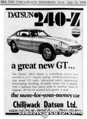 Great posting of a dealer ad from back in the day. There was a time when the pecking order for Japanese imports went like this: Honda Datsun (not Nissan) Toyota everybody else Now the pecking order (for all brands, not just Japanese) seems to be: Toyota everybody else
 -
What Jim said. The forty-year-old copper wiring will often be coated with a hard black tarnish. In fact, out of curiosity I completely stripped off all the insulation from one of my harness-to-headlight wires and found that the surface corrosion on the wire strands extended over pretty much the whole length of the wire. Doesn't impair the actual conductivity of the strands, but it will create high resistance at a mechanical connection (and it won't take solder, either). FWIW, I've had good results cleaning up the wire ends, pre-crimp, using a wire wheel (steel works faster than brass) in my Dremel rotary tool. Orient the wire wheel so that it spins along (rather than across) the wire strands.
-
Another vendor: Vintage Connections sells a pair of terminal removal tools (along with a full range of new terminals, shells, and crimping tools). The terminal removal tools work very well -- much better than any DIY solution I could come up with. Not expensive and highly recommended. Same for their crimping tool (and don't try to do this job with regular pliers -- the resulting mechanical and electrical connections be suspect and without a properly-formed crimp you won't be able to get the terminal to insert back into the plastic shell). As Chickenman says, it's better and easier to replace the old, corroded terminals than to try cleaning them up.
-
If you're interested in the history of the industry, 'Boss' Kettering's biography makes an interesting read. One other component of the capacitor story that adds uncertainty is the report that the foil-in-a-can designs used for automotive applications apparently have a shelf life and lose their effectiveness over time. So that shiny new replacement that's been sitting on a shelf in a warehouse or parts-store for years may no longer be 100% effective. Or so I've read.