
Zed Head
Community Member
-
Joined
-
Last visited
Everything posted by Zed Head
-
Have you measured the pressure coming out of the mechanical pump, between the pump and the carbs? Don't know if you mentioned it, this is page 11.
-
The first one looks very interesting because it's adjustable and has a vacuum reference port. Do you have some internet links or part numbers? I've found that many of the older parts that would be valuable for the Z's are not actually available anymore. I built a vacuum reference adjustable FPR for my engine but now you can't get the FPR that I started with. NLA.
-
Found a book. https://www.amazon.com/Carburettor-High-Performance-Manual-SpeedPro/dp/1787111687
-
I'll bet that SU's have problems with high performance cams due to the nature of how they work. One problem with cammy engines is that they tend to run poorly at the low RPM where they sound the coolest. Really, to smooth things out, idle PRM should be raised to give a more consistent intake vacuum. But then you lose the lope. That piston is probably jumping up and down with each intake pulse.
-
Once the pressure is set the gauge can come off. No real need for a permanent gauge.
-
These look decent. Holley has been collecting brands and rebuilding their reputation so quality is probably fair. A selection of psi ranges. You would want the second one, I think. https://www.summitracing.com/search/part-type/fuel-pressure-regulators/product-line/holley-fuel-pressure-regulators?SortBy=Default&SortOrder=Ascending
-
I wouldn't use it. A decent gauge, those hose clamps, and pieces of hose would cost over $25. It's universal because they can change the ad copy to fit any application. 140 psi. "adjusts oil flow"? "ideal weight"? Not good... Fuel Pressure Regulator Kit: Prevent stalling, flooding, and other drivability problems by making sure your carbs are getting the right amount of fuel pressure with MOJTBE products. Adjust Capacity: This Aluminum Fuel Pressure Regulator Kit is adjustable from 0 to 140 PSI maximum fuel pump capacity. Optimally adjusts oil flow to meet your car's fuel pressure requirements. Materials: Premium aluminum construction for ideal weight and superior durability. Package Includes: 1x Fuel Pressure Regulator, 2x Hoses, 1x Accessories. NOTE: Not Legal in the state of California & New York, Not complies with C.A.R.B. regulations, Not for sale in the states of CA and NY. No instruction or direction included in the package, Professional installation is highly recommended.
-
That's an odd one. Looks like it has a vacuum reference port, which a carburetor would not need. But a 10 psi gauge which is way lower than any EFI system. Post the link, can't even tell what brand it is. Looks like eBay.
-
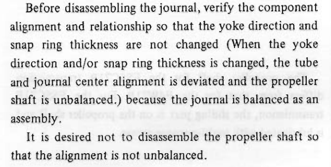
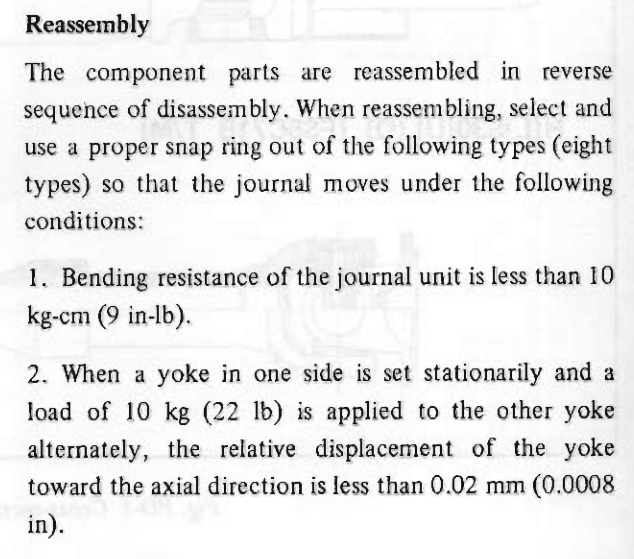
It might also be that they were putting in the extra effort to perfect the installation. "Blueprinting" the u-joint and shaft with extra care.
-
You're agreeing?
-
It's hard to imagine that Nissan would have a had a fixture that aligns the companion flange or transmission shaft with the future center line of the propeller or drive shaft, so that a worker could choose the proper snap ring thickness, while measuring play. More likely that they had a set of go/no-go gauges and sorted the shaft yokes by the width between the ears and assigned them a snap-ring color. The area between the areas would have been cut with the center of the yoke as the reference point. I think that somebody rebuilt that u-joint in the past and just used the wrong color or was colorblind, or didn't care.
-
Looks like one of those conflicting instructions areas. They say "don't change anything" but if you do change them so that certain conditions are met. Kind of like wheel bearing instructions - rotational torque or axial play? You have a dilemma.
-
Putting the image on the front page where people will click it kind of creates a cycle. I guess that explains it. Once it's on top it stays on top. Just wondering what the purpose was. Random images would be more interesting. Something new every day.
-
Just realized that I've been looking at the same "popular image" for many many long time.
-
How about a picture of the impeller? The other side.
-
This does not appear to be the case. Never knew about that feature, never sent an email or shared anything, or posted anything associated with my CZCC screen name. Don't of any of the mainstream social media things. Maybe @Route66 could share how they got the referral link. Welcome to the forum Route66! How did you hear about it? Supply details...
-
Who knows... https://www.classiczcars.com/profile/45020-route66/
-
I wonder what else is getting sent out from "Zed Head" at CZCC.com. Weird. I'll check out this Route66 person. Bet there's a web link in the profile.
-
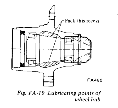
The seal has a seat in the rotor. The inner bearing will be pressed against the outer bearing race after installation so there will be no wobble. It will be wobbly while it's off the spindle but not once it's installed. Here are some pictures from the FSM. There's a gap.
-
Funny, I forgot completely about the typical low output alternator problem. I've never heard of it affecting tachometer operation though. Maybe the combination of parts causes it. You can get 60 amp external regulator alternators. I think that the 280Z's all had them, until 1978 when they went to the internal system. Might give a little bit more current/voltage at low PRM. Thanks for the compliment. I appreciate a good puzzle.
-
Ouch.

-
Anybody else get a notification like this? Don't know what it means.

-
Seems like what you really need to do is move the power supply source for the fan. The tachometer and MSD aren't the source of the problem. It's the power supply to the tachometer and/or the fan.
-
It would depend on current flowing through the transistor, the one in the drawing (if that's what it is). It's that meditation law. Oooohhhmmm...
-
The MSD tach wire bypasses the multiple sparks. That's the reason they have it on the MSD component. Not sure what you mean by blue wire taped up by the coil. How is the MSD tach wire connected to the tachometer? If you could draw out your circuit and post it somebody might have some ideas.