Leaderboard
-
HusseinHolland
Free Member7Points1,031Posts -
grannyknot
Free Member5Points5,158Posts -
Jeff G 78
Free Member5Points3,007Posts -
Yarb
 Subscriber
 4Points1,935Posts


Popular Content
Showing content with the highest reputation on 11/19/2023 in all areas
-
You don't have to buy new handles. You can simply swap the handles left to right. They are identical and have two arms each. When an arm breaks off, the unused arm is still good. When you swap them left to right, you are using the good arms on both handles.5 points
-
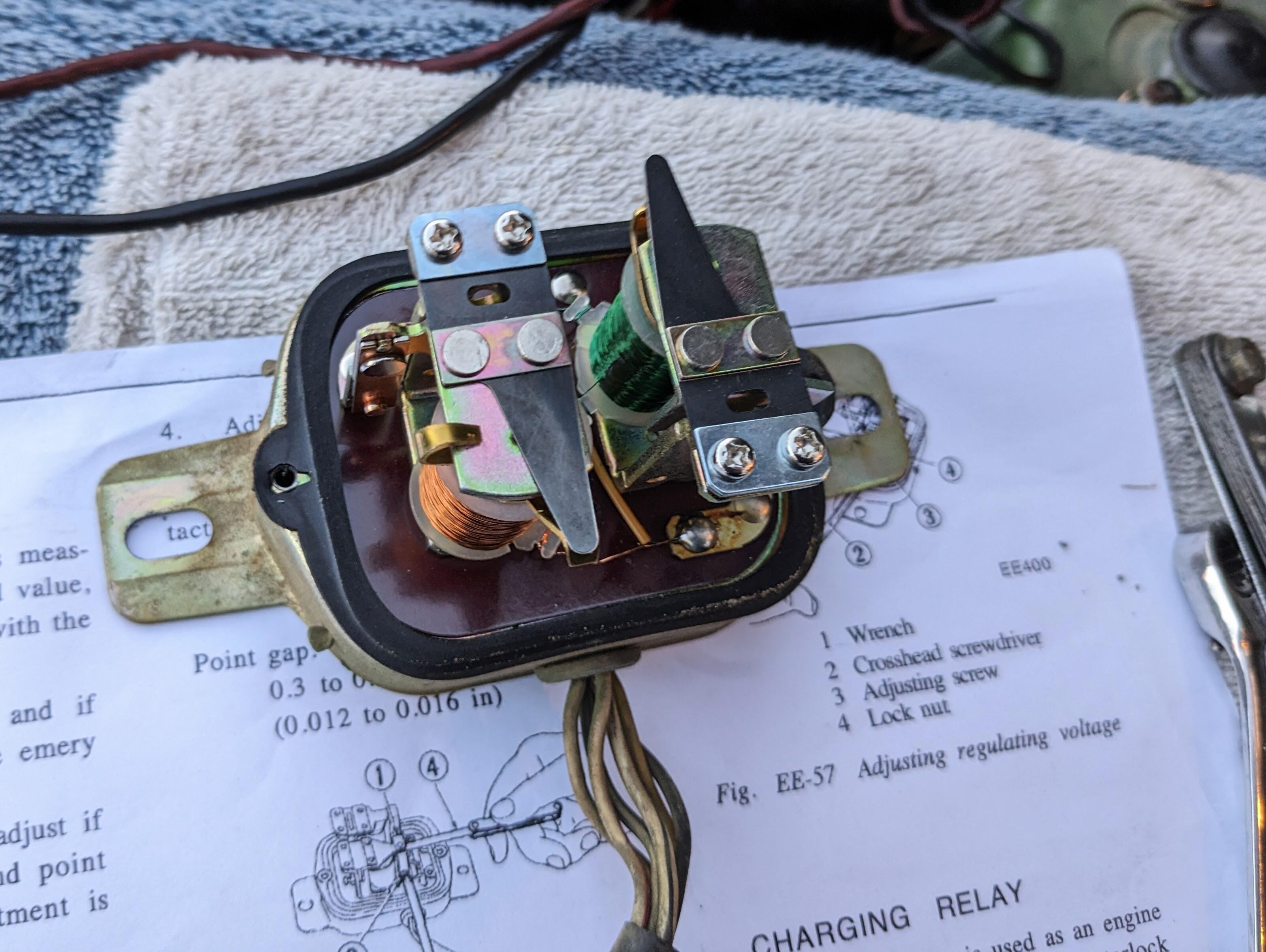
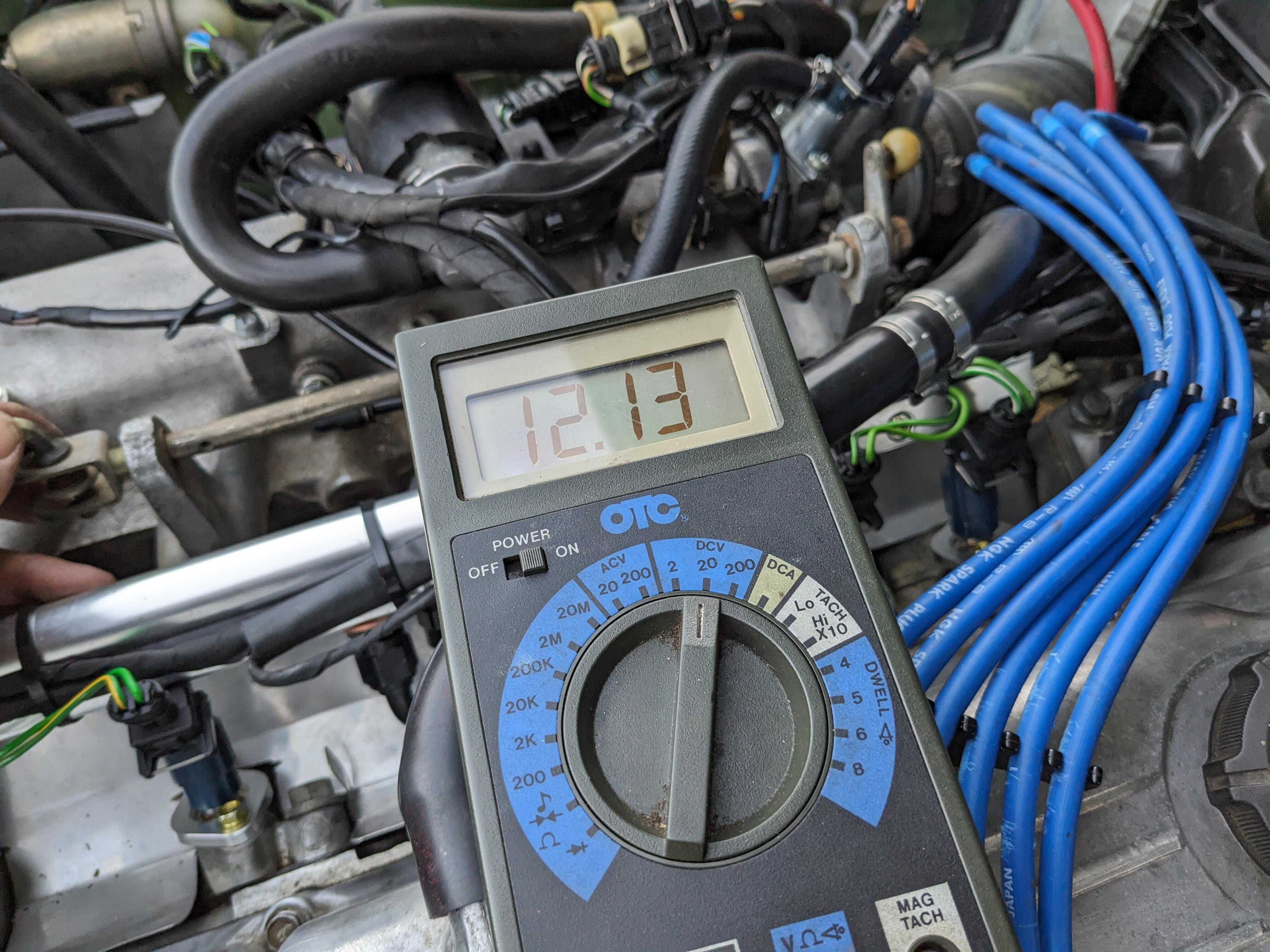
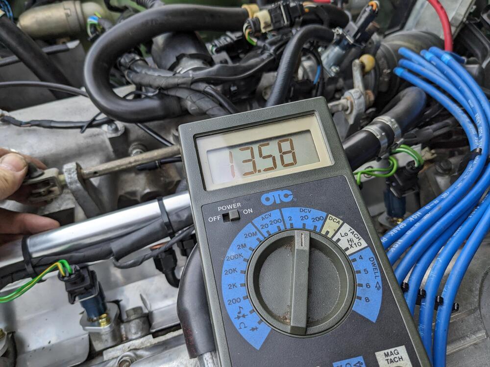
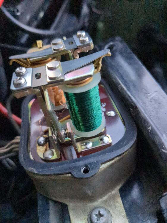
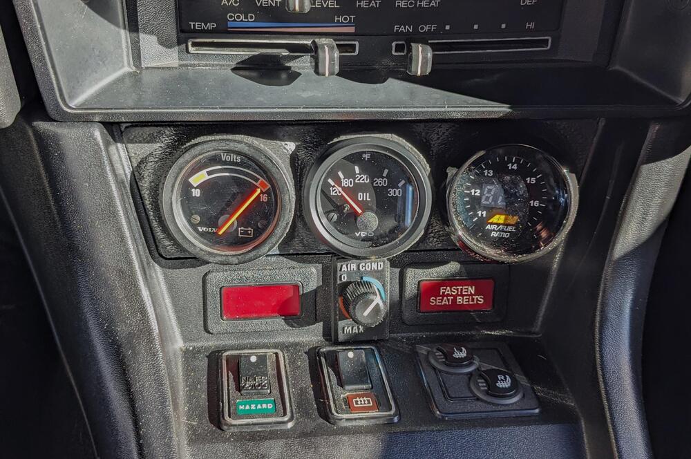
Adding to this rather than start a new similar thread. My system puts out 15.5-16v as soon as the engine is revved over 2500rpm, regardless of load. Sometimes it spikes to that off idle. Seems hair-raising to me. I'm used to 14.1-14.5V being optimal on my Swedish & Italian cars. This was around 1800rpm I read how to adjust it in the service manual, however mine did not match the diagrams. I had to adjust the point gap by loosening the two top screws. It was unclear which side of the points was supposed to be checked @ .012". After initial adjustment I was only getting 12V any any rpm, so I decided to adjust it while running - that way I was able to check idle & high rpm values for consistency. I settled on 13.8-14.5 range, as tweaking it outside that just need up with either too low or back to 16V range. My points do have some pitting, so I sanded them to remove the peaks at least. core gap on left, point gap on right Point gap seems to be the left side standoff on mine. When I set the larger gap on the right side, it didn't charge at all initial adjust final setting - goes from this to about 14.5-7 max. Seems good to me


 3 points
 -
Excellent. With newer injectors so much easier to find than the old ones, it's great to figure out alternative!2 points
-
10-11 is just dumping gas. Even with a high pressure Turbo, you really don't want much under 12 for good power. I was mainly checking that I had uniform values at all the injector sockets, since they all originate from those 2 wires that feed the ballast. Just to be clear - the AFR's weren't on target with the ballast in place - I had the lean condition at warm idle, and some unevenness under load conditions. It did feel better than the stock injectors, but now it feels really smooth by comparison, so I'd say removing the ballast is wise with high impedance injectors.2 points
-
2 points
-
2 points
-
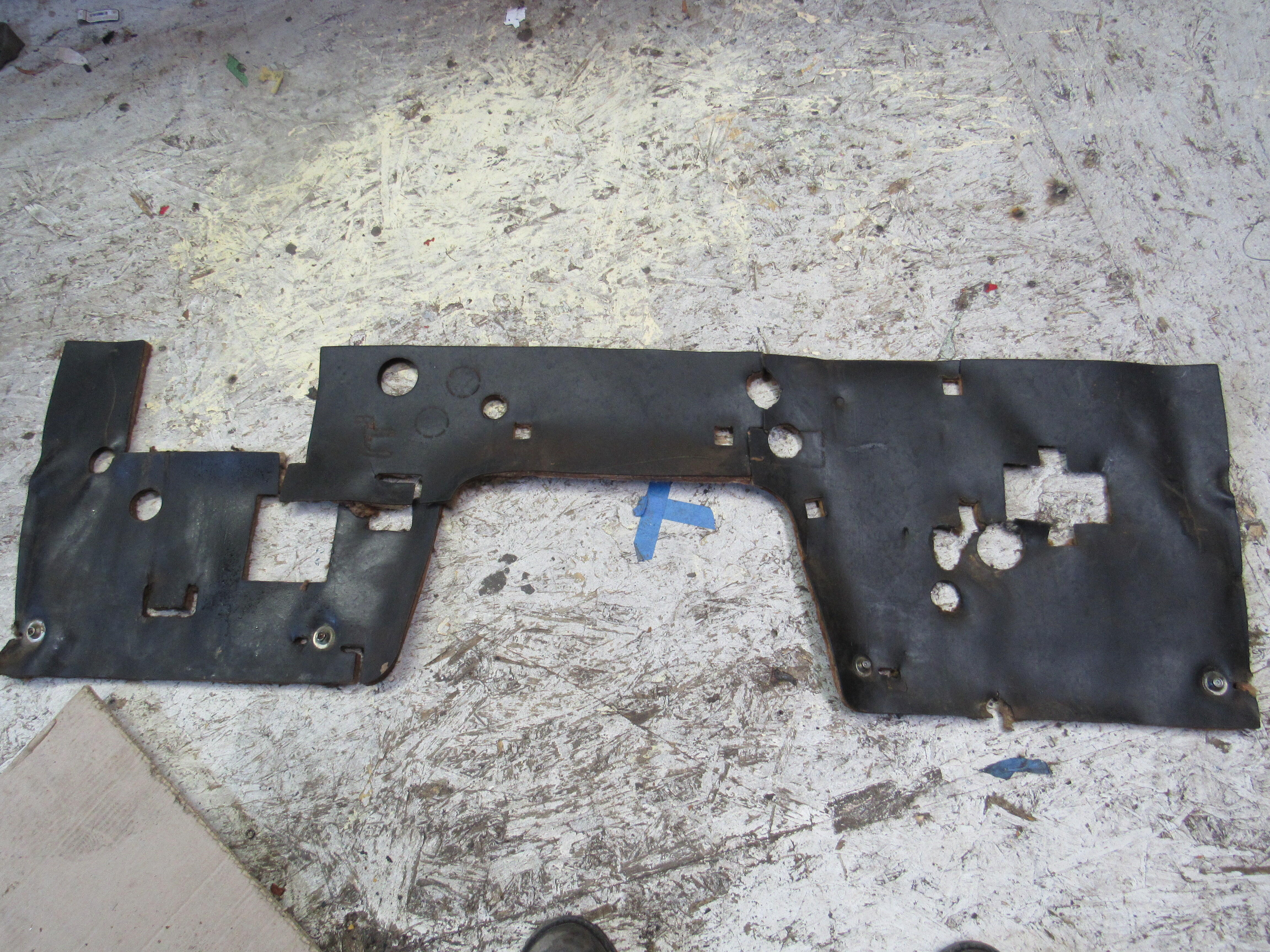
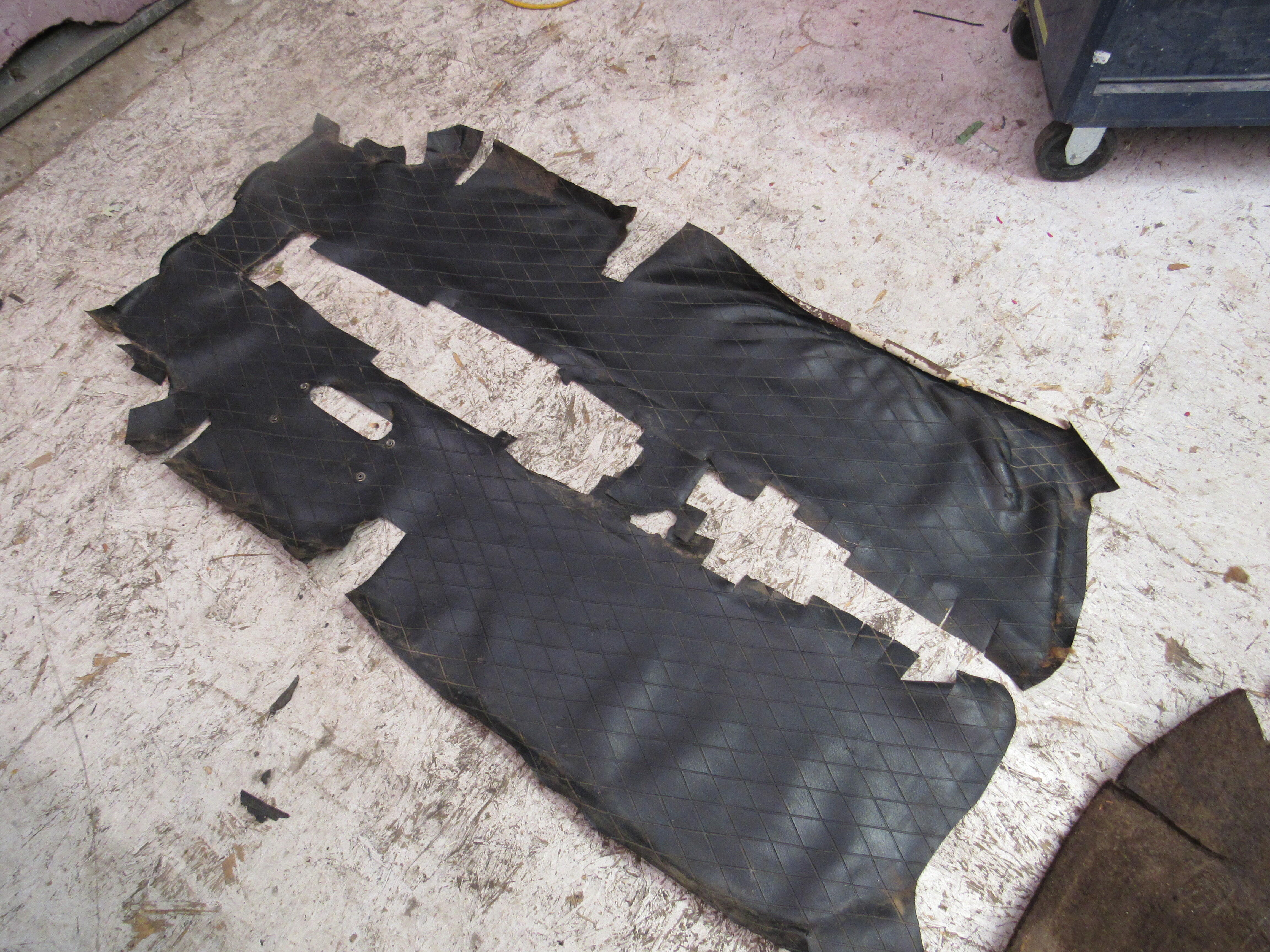
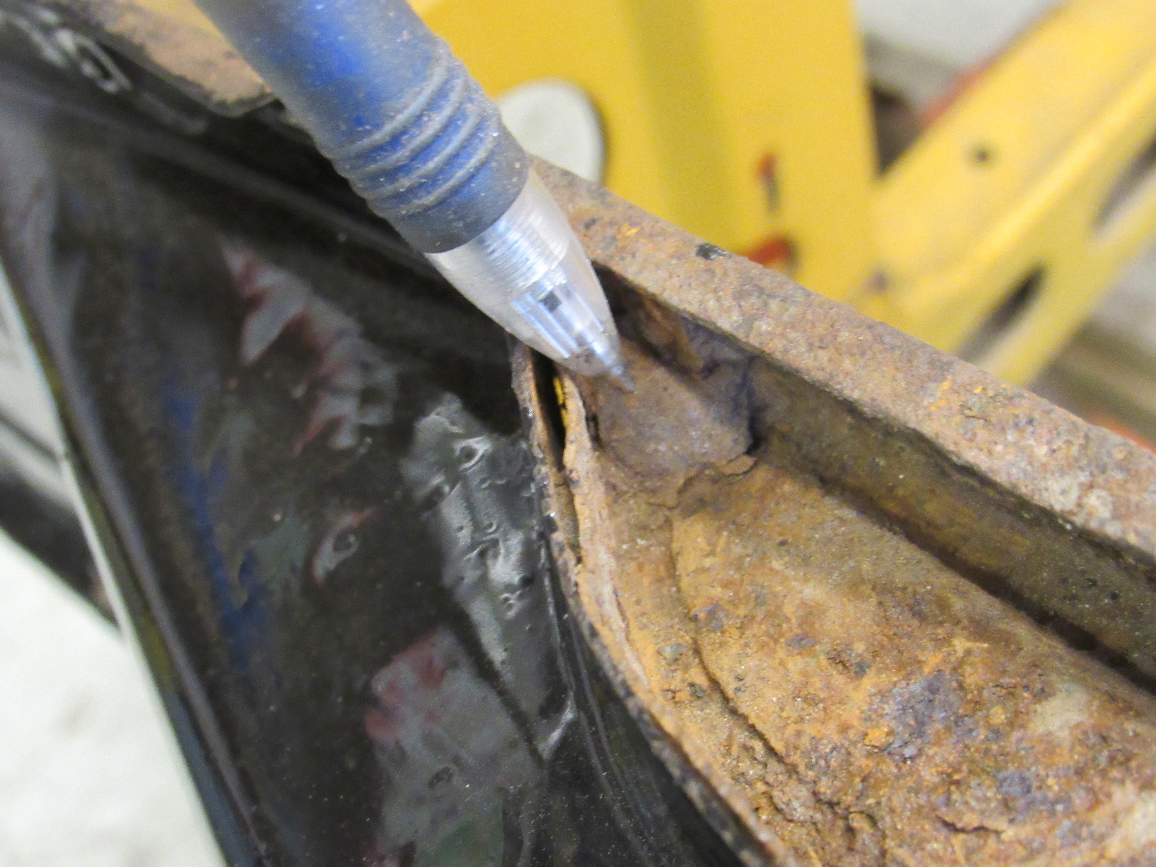
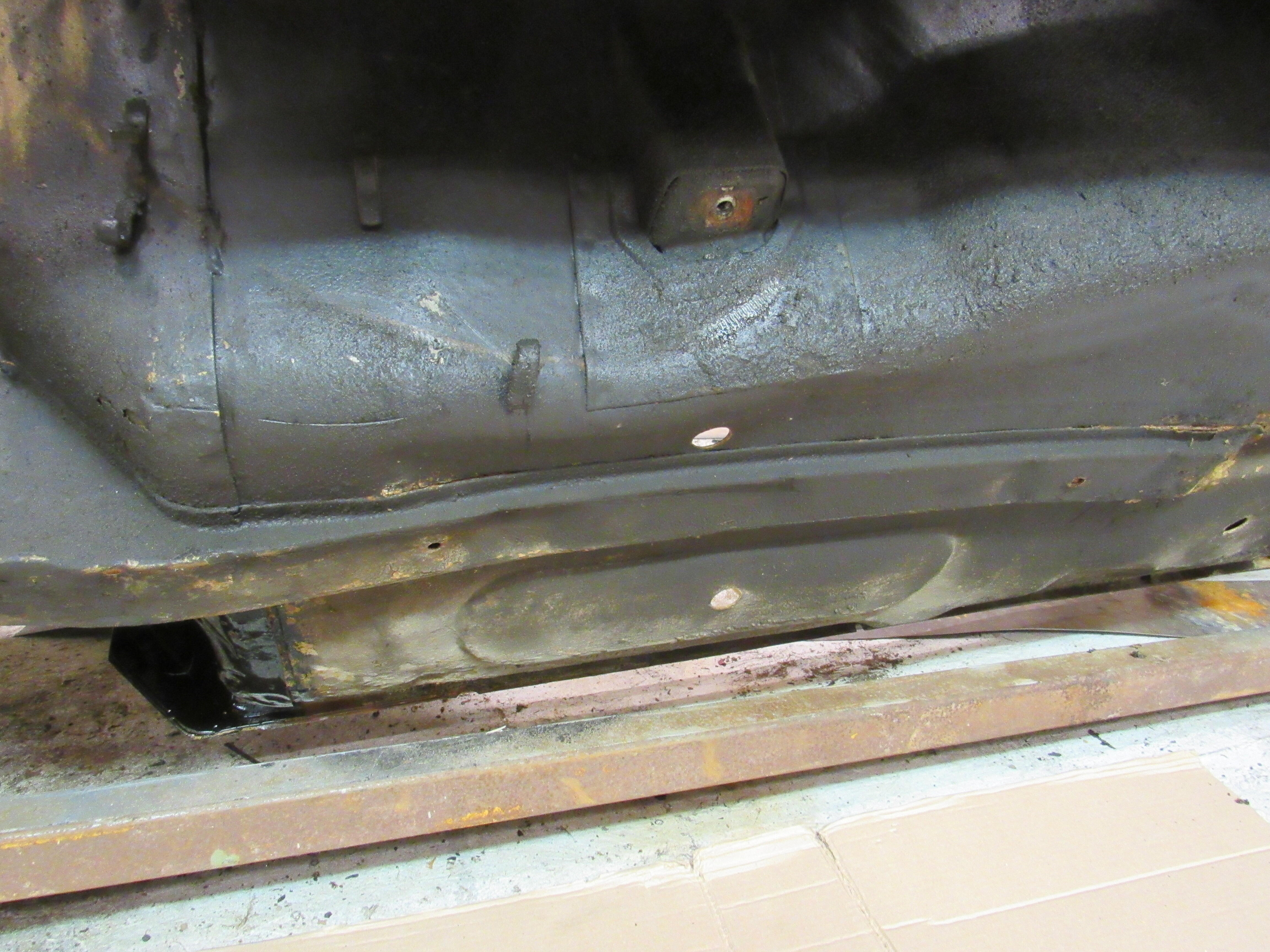
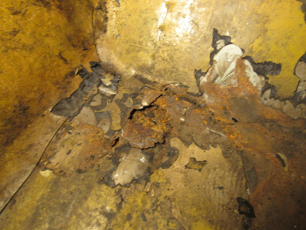
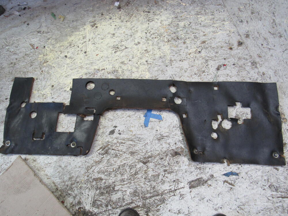
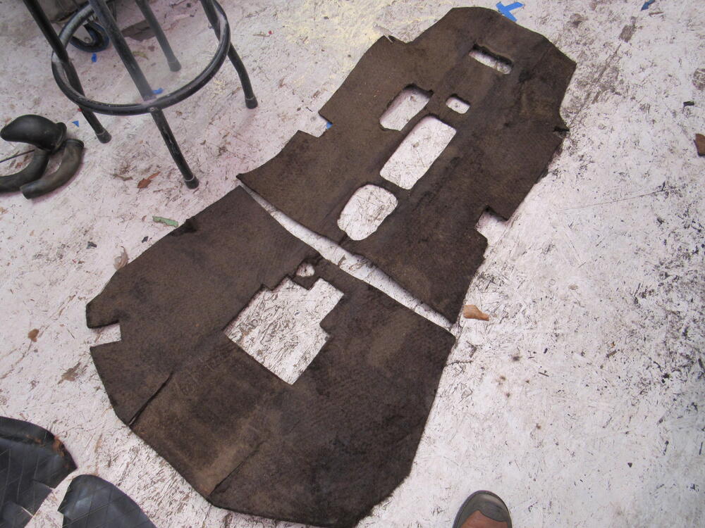
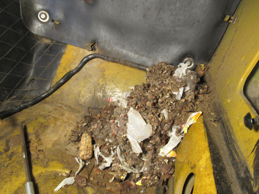
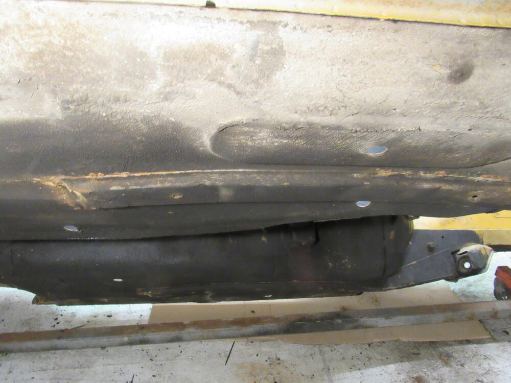
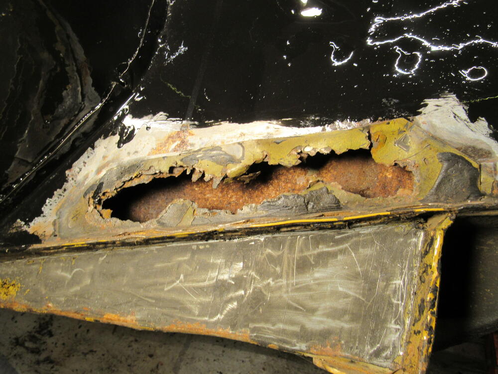
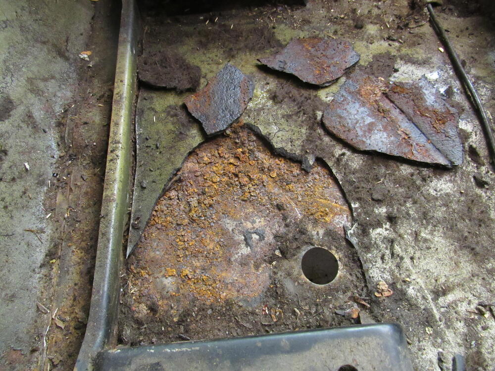
1 pointI started chipping away at the tar mat today, oh what fun I was hoping I could save the floor pans but they are too far gone, water was pooling and the rust is bad. I manged to remove the firewall insulation, vinyl cover and original trans tunnel insulation and I can reuse all of them. Also found another long term tenant, this was only half of what was came out, the rest I had to get by sticking the vacuum hose through the vent.


 1 point
 -
1 pointSounds like you sorted this out but it was my understanding that the +8 caliper was for the non vented stock rotor and the W was for the wider vented rotor. I have had mine on the non vented rotors for some years now and may recall incorrectly.1 point
-
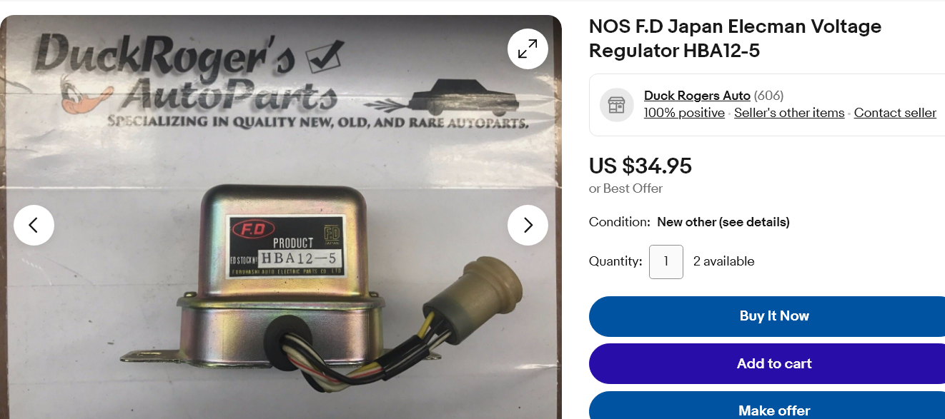
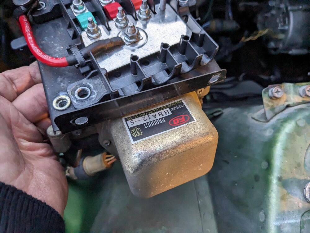
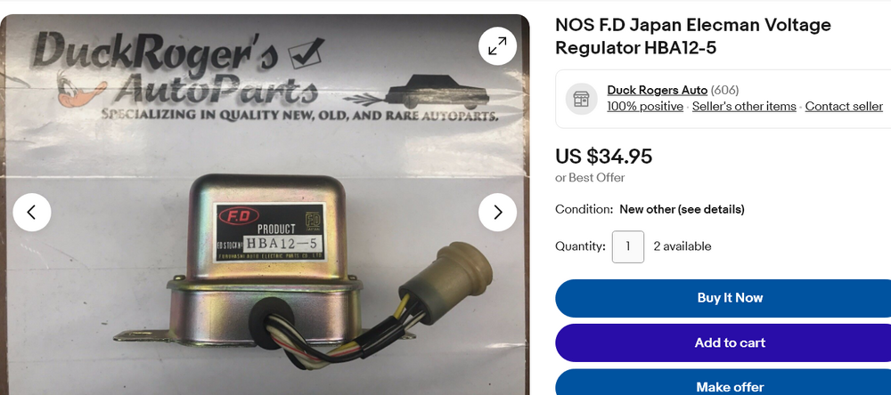
I've not seen that brand name before. Interesting. https://www.ftonline.co/product-category/electrical-parts/voltage-regulators/ https://www.ebay.com/itm/234598216098?mkcid=16&mkevt=1&mkrid=711-127632-2357-0&ssspo=MOJzyVjhShe&sssrc=2047675&ssuid=bBzFtXzvTQO&widget_ver=artemis&media=COPY
 1 point
 -
1 point
-
1 point
-
1 pointI went to O'Reillys and matched the uninstalled rotor with calipers for a 91 4runner v6. There are two options for 91: - to 05/91 (pn 19-1240 and 19-1241) that had s12w stamped on them - from 06/91 (pn 19-1600 and 19-1601) that had s13w stamped on them The rotor fit on both. The only difference I saw was the piston size: 42.7mm on the s12w and 45.3mm on the s13w. Didn't buy them because they were just the basic O'Reilly brand but now I know what I need.1 point
-
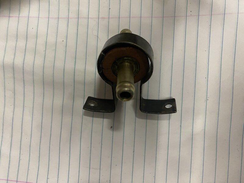
1 pointThanks for the info everyone! Okay, quick recap: 1. The silver check valve connecting two black hoses is for the brake booster vacuum. The black and gray one I have is also a brake booster vacuum check valve. The red ring is for the silver valve. I will test the silver one. If it works I’ll use it. 2. The 240 Z did not have a check valve in the vapor lines prior to (I think) 8/73. There is one on the brake booster, one on the smog system, and a flow valve on the left inner fender for vacuum lines. There IS one on the vapor line for cars that came with a charcoal canister (9/73?). I think there is also a fuel check valve between the fuel pump and the fuel rail on FE equipped cars. *** I think I will set up the fuel lines as they were OEM and investigate having one after the fuel pump somewhere (both placement and necessity).1 point
-
1 point
-
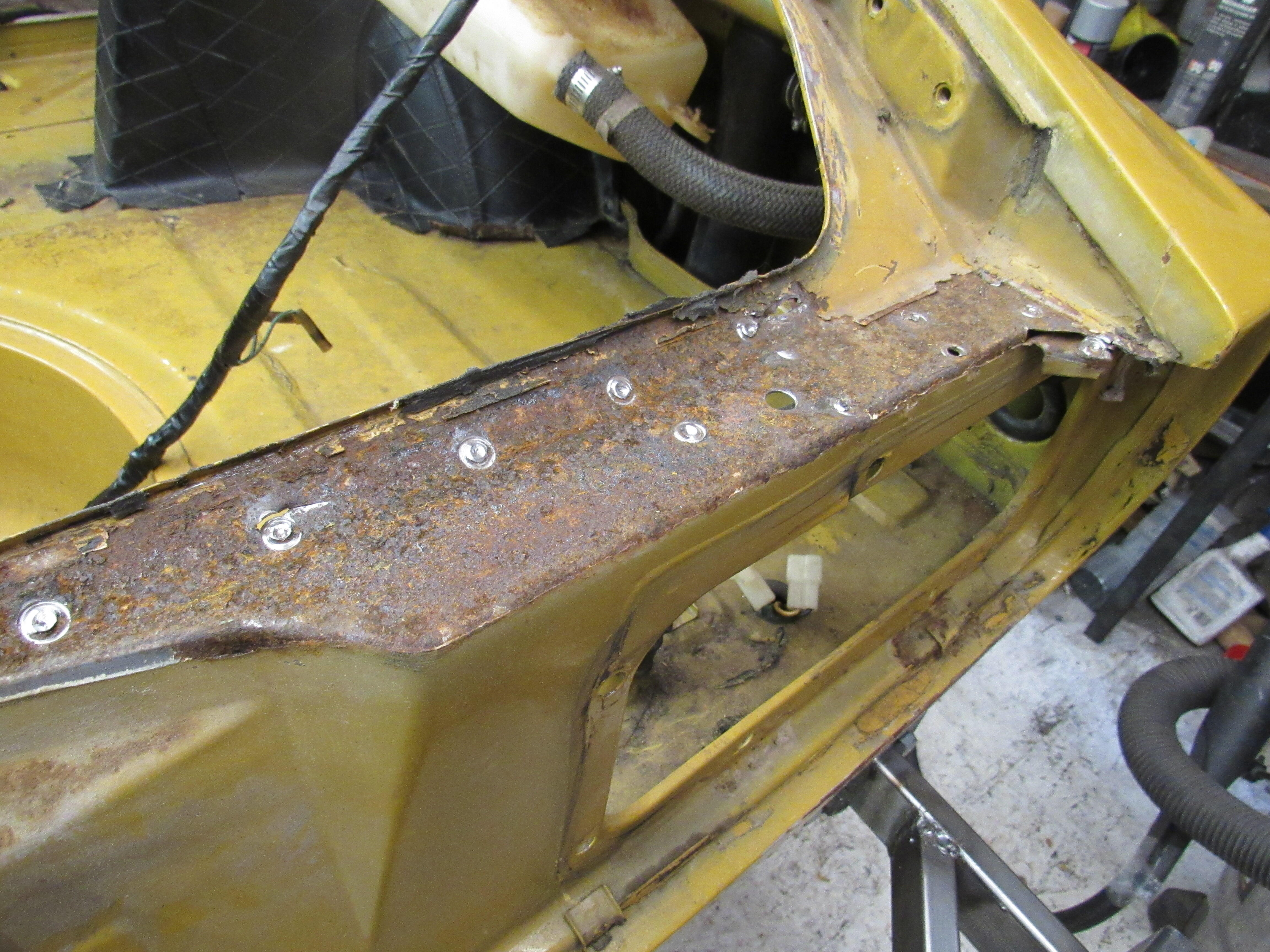
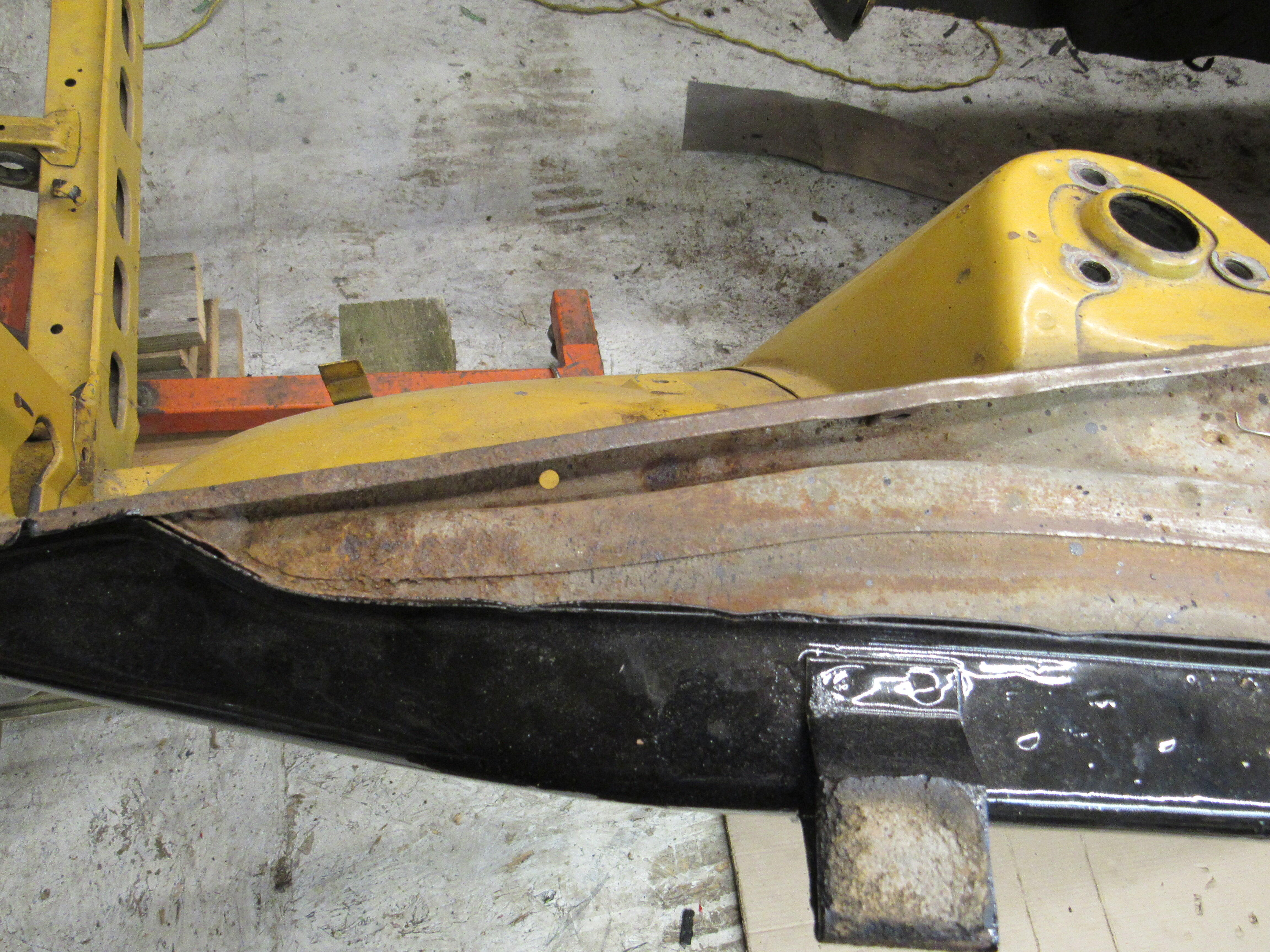
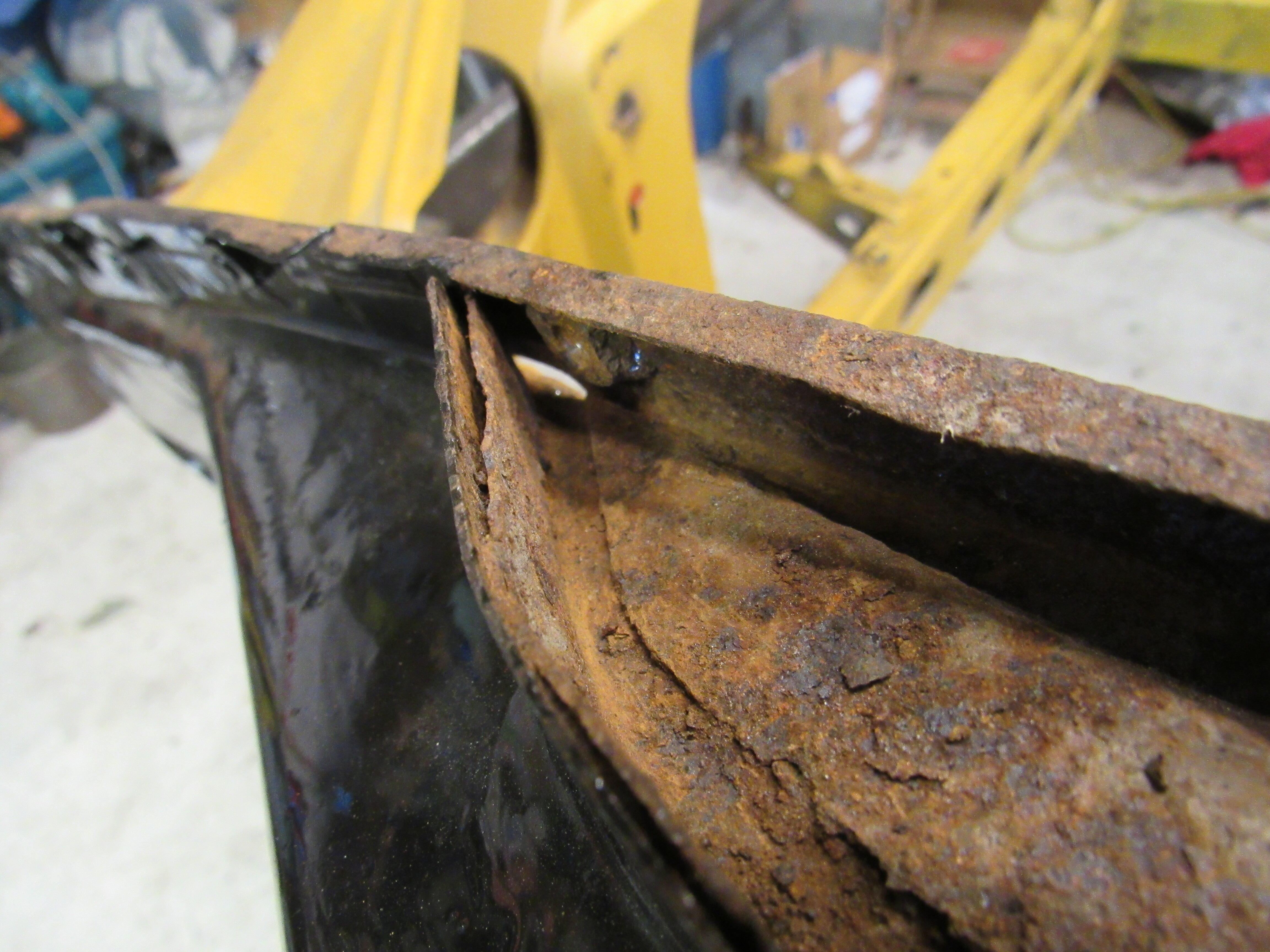
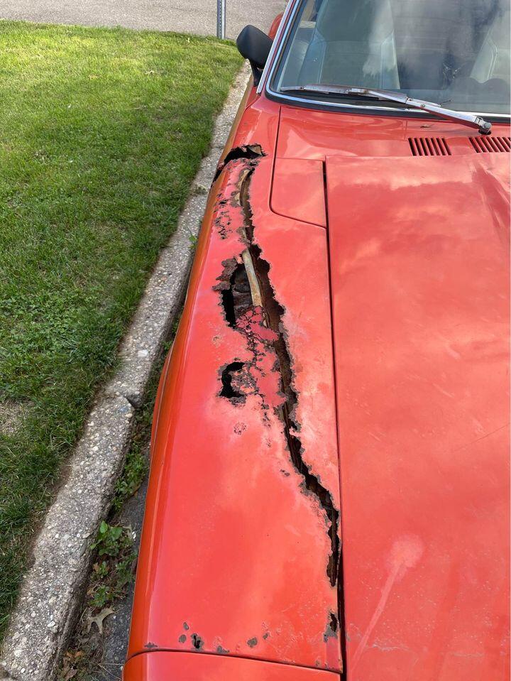
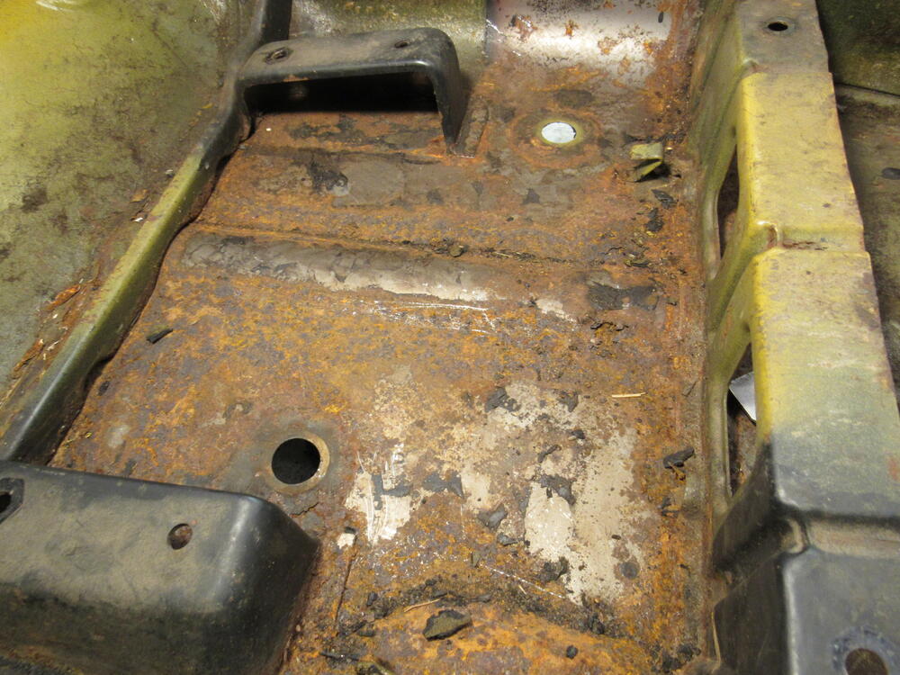
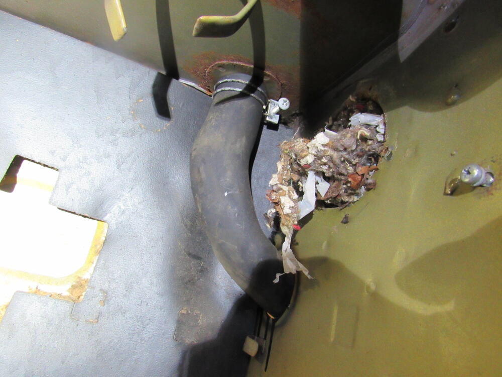
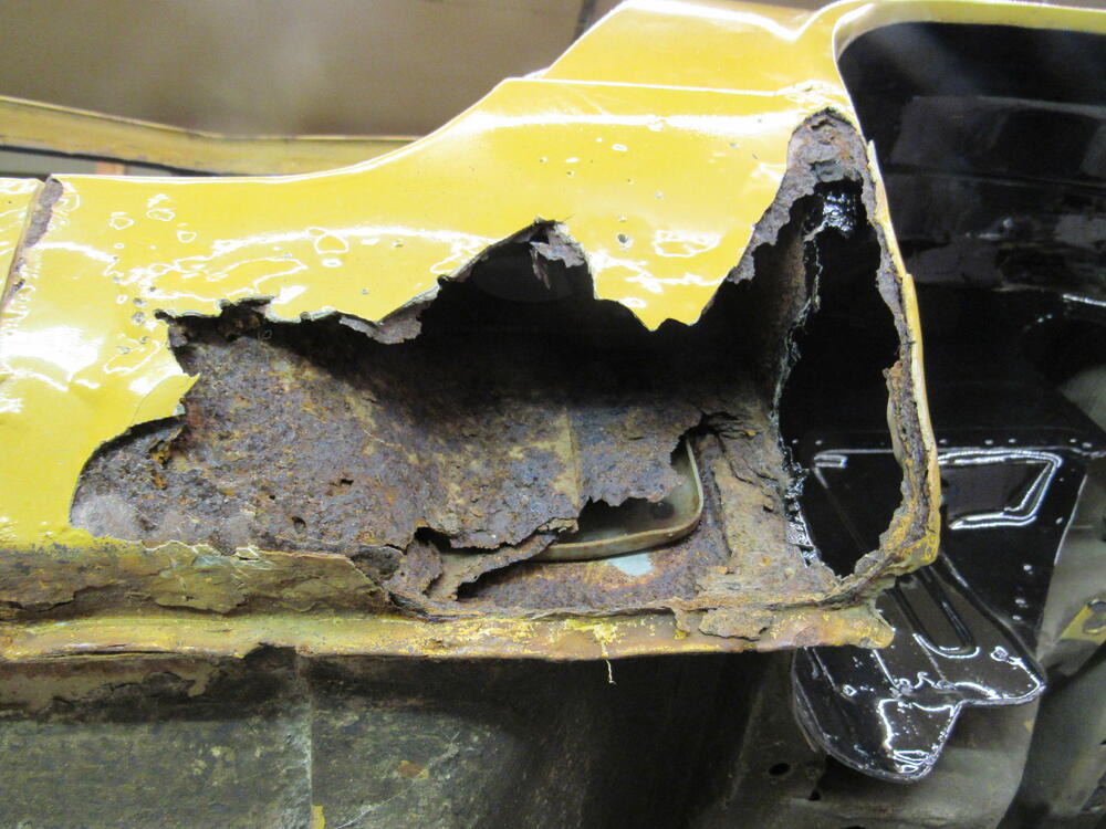
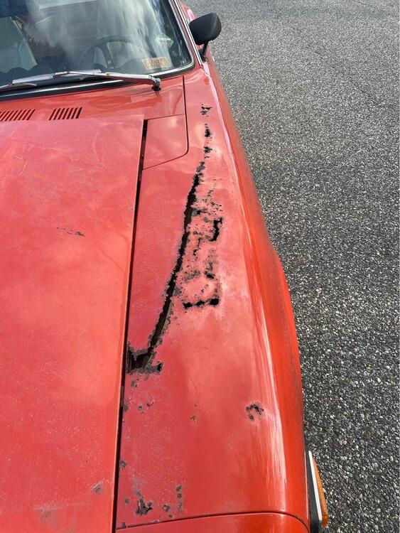
1 pointOoooo that's nasty. Open cell foam will defiantly hold water but closed cell won't. In your first photo showing the passenger side fender it looks like the original rubber seal is still in place. For some reason on the assembly line, a blob of seam sealer was applied blocking the drain hole on top of the wheel well. Any water that does make it past the original rubber seal just sits there in a pool eating away the metal. It's a hard place for water to evaporate from. The last pic I have chipped the old seam sealer out and cleared the drain hole.


 1 point
 -
If you run into a problem send me a pm. I can probably help you out with a set.1 point
-
1 point
-
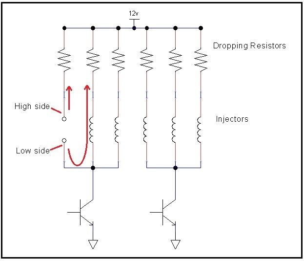
The AFR numbers look good. I'm no engine tuner, but I don't think 10-11 at WOT is that bad. Maybe a tad rich, but you usually want it rich at WOT, don't you? As for the resistance measurements, most of them look good. The two where you are sticking the probes into an empty injector socket (to measure back into the harness) really don't tell you much though. You're just reading a combination of ballast resistors and injector resistances in series parallel combination. Didn't hurt anything, but really no good data to be gleaned from that. If you're not sure what I mean... here's a pic that highlights the situation. You're just measuring a couple injectors and their dropping resistors in parallel, etc. In theory, if you're measuring back into the harness with the key off, you should read open circuit. But you would have to disconnect all the injectors (or at least the correct three) to see that. if you crank the meter up to the 2 MegOhm range. you might be able to pick up the leakage current through one of the output transistors in the ECU, but that's about it. So for the rest of the resistance measurements... You measured the ballast resistors at 5 Ohms and the injectors at 15.5 Ohms. Those measurements look great. Let me think about those numbers a little. In the end, if your AFR's are good, all that theory by the Volvo folks doesn't really matter. Might be applicable, might not. But your AFR's are on target, so who's to say there's a problem?
 1 point
 -
1 pointMake sure the check valve arrow is pointing to the booster, Not the vacuum source! Ask me how I know!!1 point
-
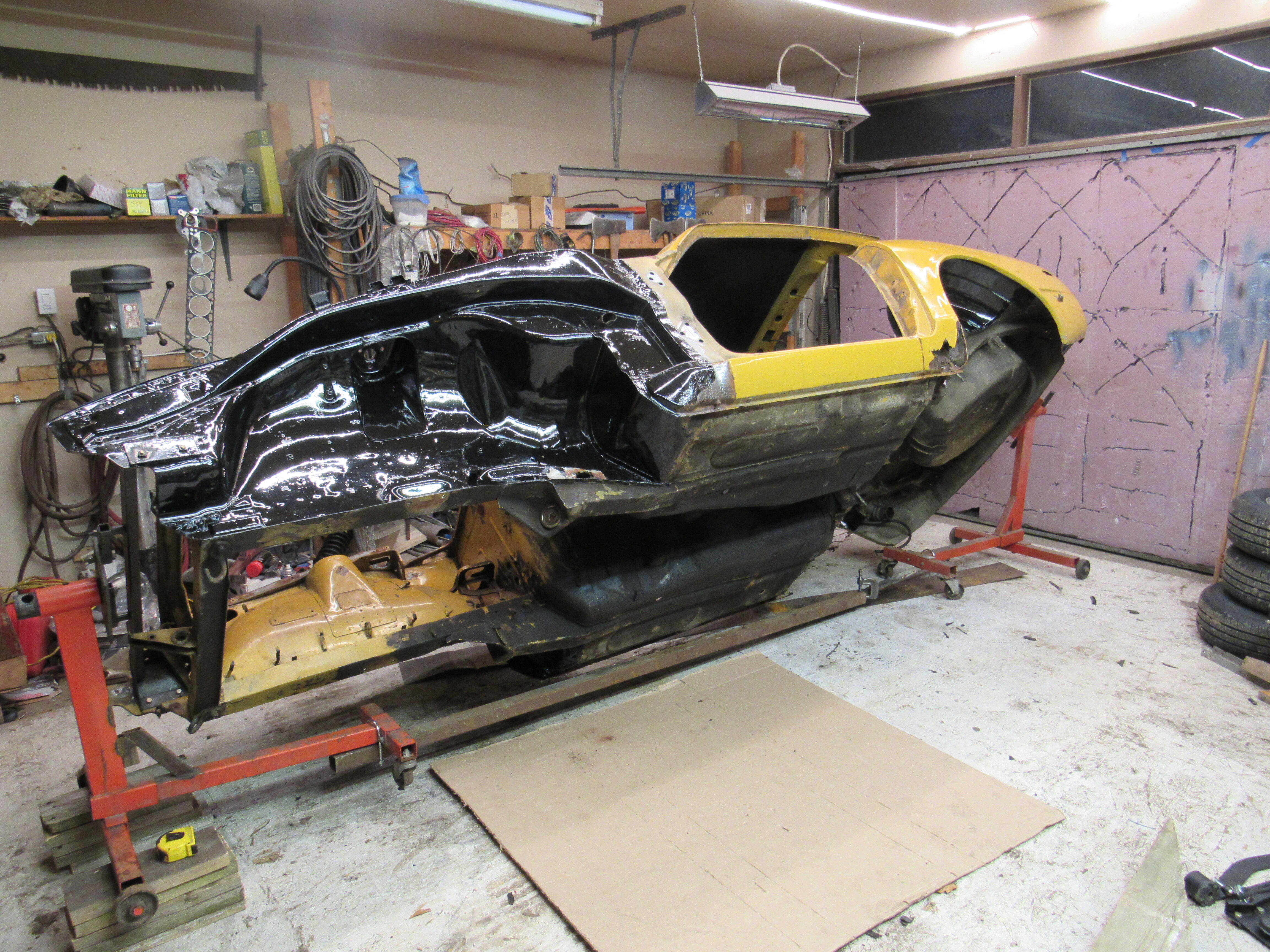
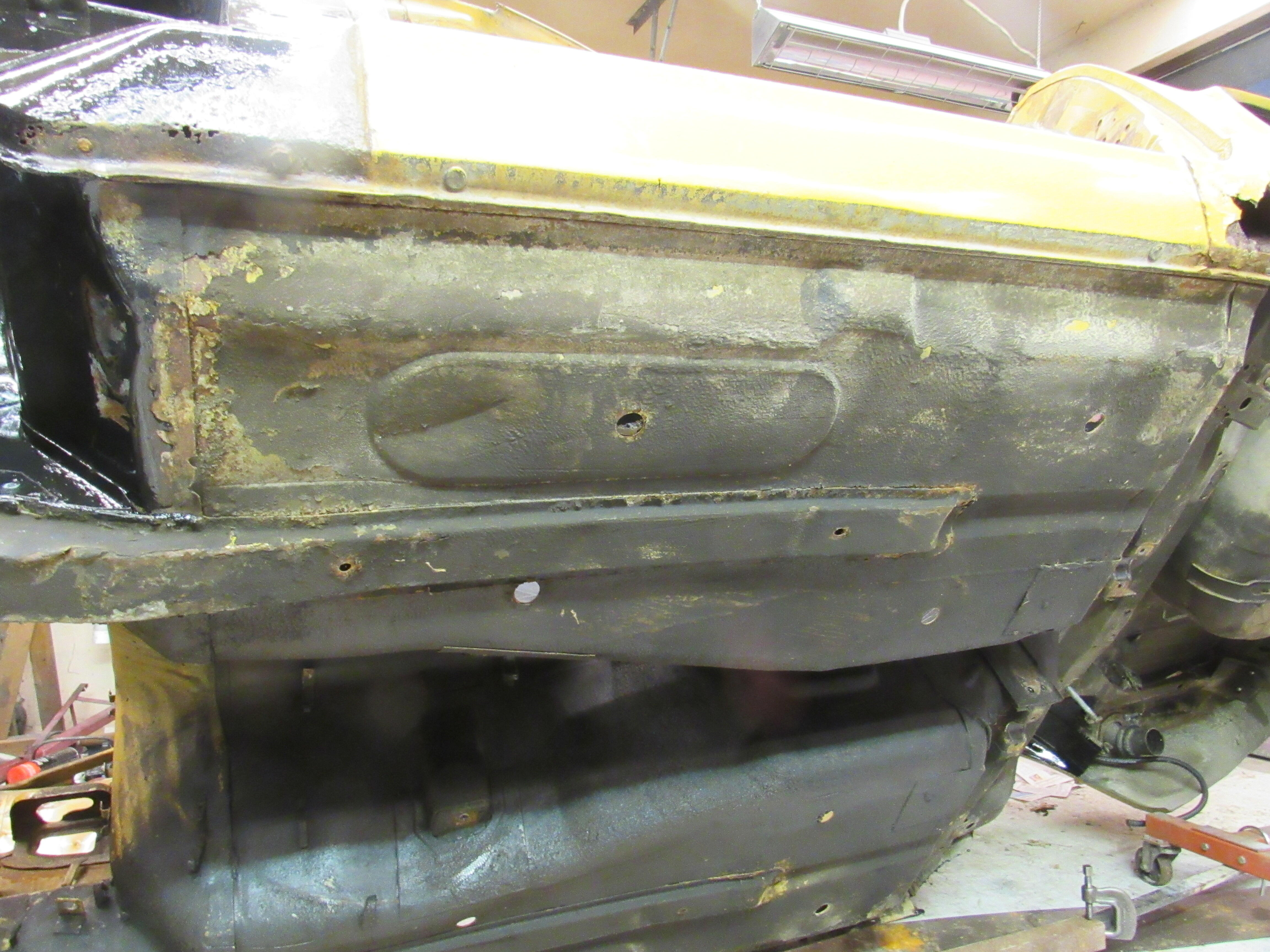
1 pointWell she's up in the air, like an idiot I sold my good rotisserie last fall thinking I would never use it again. So I had to dig out the old one, not very pretty but it works fine. Someone jacked the car up in the middle or the floor pan, I have an anvil that I p/u and drop to correct those. Some rust porn.


 1 point
 -
Another link - some amazing Z's... https://www.mecum.com/videos/the-st-yves-datsun-nissan-collection-mecum-kissimmee-2024/?fbclid=IwAR0QDyChMOcEkXUzE7oQyUJQH6eceyWdy7AohIJ8Du-73GRTBOiPmWHjfe81 point
-
The half-shaft rebuild would involve the ball bearings and their races. I found an older thread about. It should be in the Knowledge Base section. @Mike1 point
-
I asked about the high/low ohm injector combination issue on one of the Volvo forums, as this applies to some early Volvo LH systems. One of the members had this to say: "sorry, you don't want to do that. If you use high impedance injectors with a resistor pack, it roughly doubles the resistance. This means the current flow through an injector is ~1/2, which results in ~1/4 the opening force on the injector pintel. This can cause slow injector opening and/or the injector not fully opening." Another gave more detailed response: "Your injectors are clearly opening; but, the injector offset (which some people refer to as injector opening time) is affected by the injector operating voltage which is now much lower than design. When you reduce the injector voltage the offset increases and the actual injector pulse width is reduced compared to the commanded pulse width. At wide open throttle or close to wide open throttle where the commanded pulse widths are large the error caused by the increased offset may be less significant although the engine will run with a slightly leaner fuel mixture. At idle and low engine load where the injector is operating with small pulse widths it will have a larger % effect on the actual pulse width. At worst, if the reduced pulse width intersects with the injectors non linear region you can cause extremely unstable idle. At best, the reduced pulse width will result in a leaner than ideal fuel mixture at idle and low engine loads." and "I assume that 205CC means 205 ml/min flow rate for the injectors. If so, that is not a particularly large injector which means that your idle pulse widths are fairly large and probably well out of the non linear region which means the increase in injector offset may have a less significant effect. So, the car may still operate right now; however, if you ever have to do a cold start on a cold day with a compromised battery you may run into a no start condition. The reduced battery voltage may result in a complete injector non opening condition at worst or really difficult starting" finally "The good news is that this should be easy to correct. This may be as simple as just deleting / by-passing the original injector resistors. What you need to do is measure the resistance of the original injector and the injector resistor. Add the values together. The 0280 155 712 injector appears to be really high resistance - 16 ohms. As long as the added value of the original injector and injector resistor is less than the resistance of the new 0280 155 712 injector it is 'safe' to just delete / by-pass the injector resistor. I suspect that this will be the case because most low impedance injectors were around 2-3 ohms with external injector resistors in the 5 - 10 ohm range so a total resistance in the 7 - 13 ohm range." I'm going to go ahead and bypass the resistor pack, after I measure the values.1 point
-
0 pointsMake sure not to use home center type weather seals in metal on metal situations. Those materials tend to hold water.

 0 points