


Leaderboard


 Subscriber
Popular Content
Showing content with the highest reputation on 05/12/2023 in Posts
-
4 pointsA few photos to go with my write-up. I didn't take any photos of the work that I did with my door trim panels. These pix show the same technique used for the rear kick panels...

 4 points
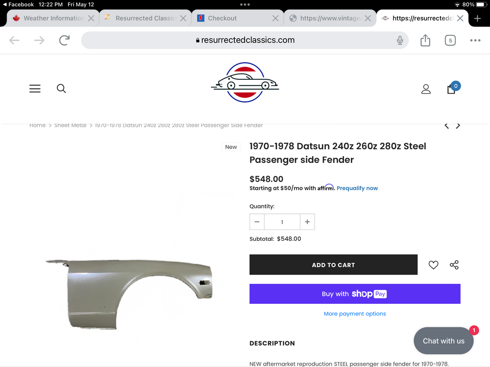
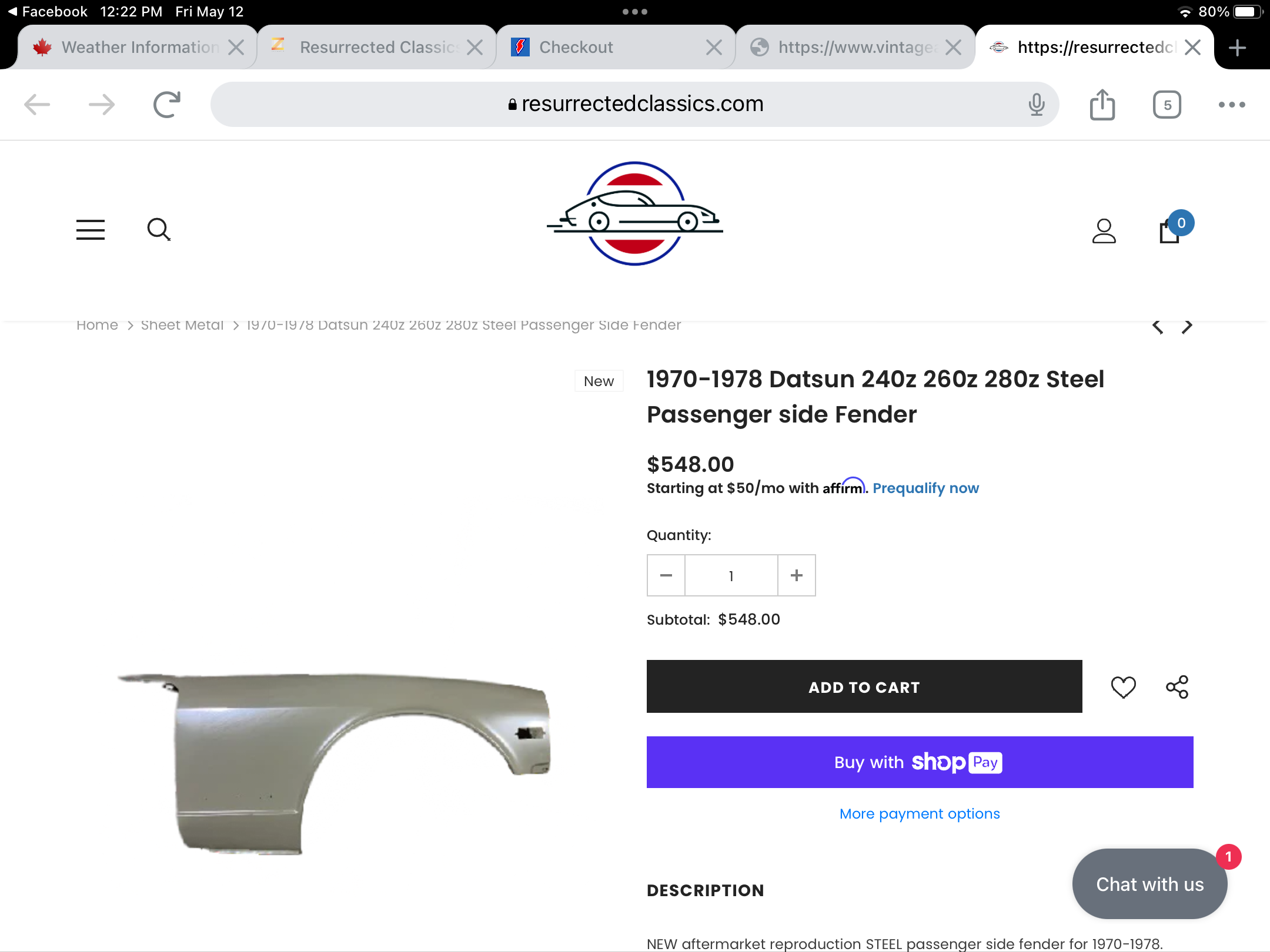
 -
https://resurrectedclassics.com/en-ca/collections/sheet-metal/products/1970-1978-datsun-240z-260z-280z-steel-passenger-side-fender
 3 points
 -
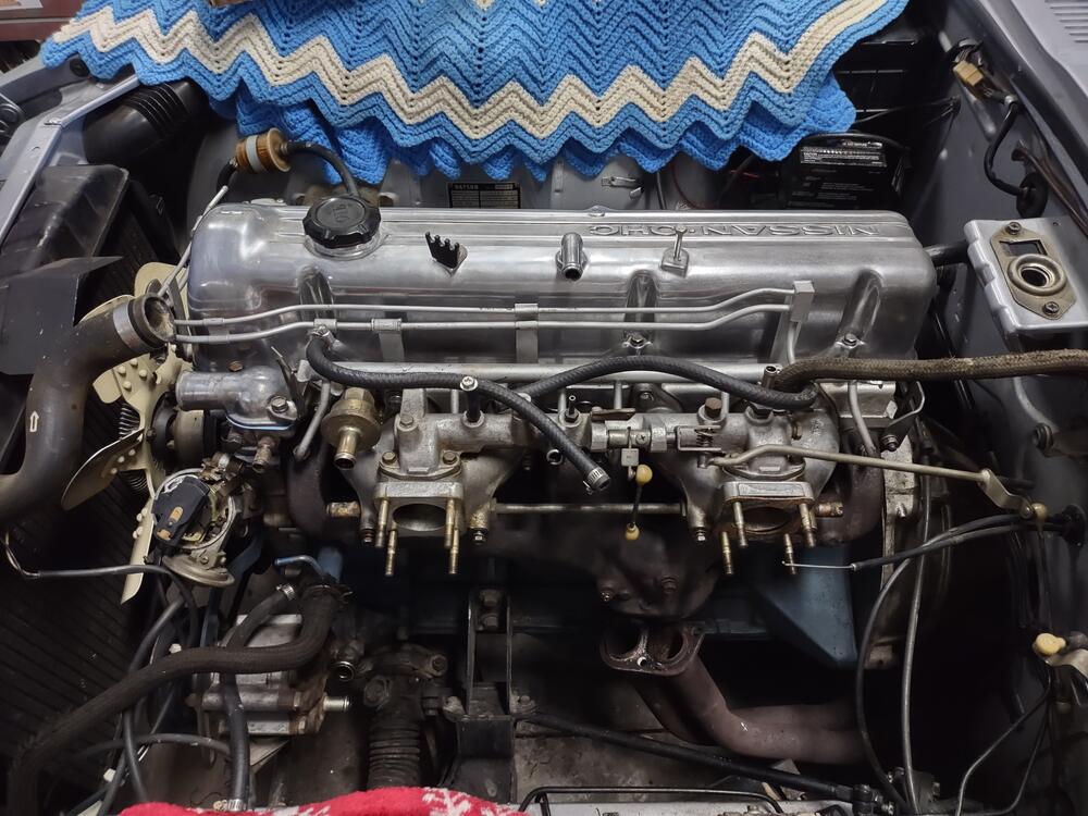
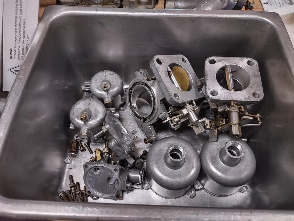
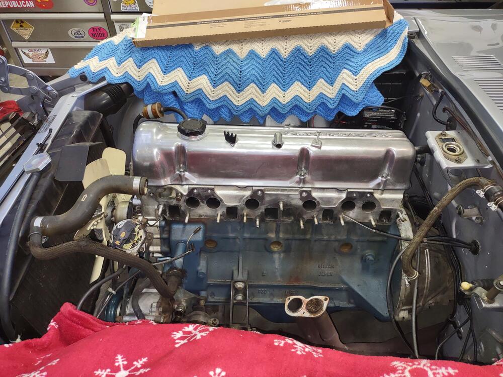
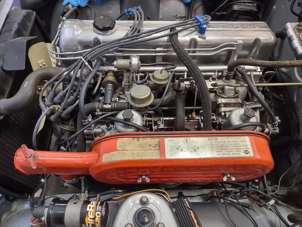
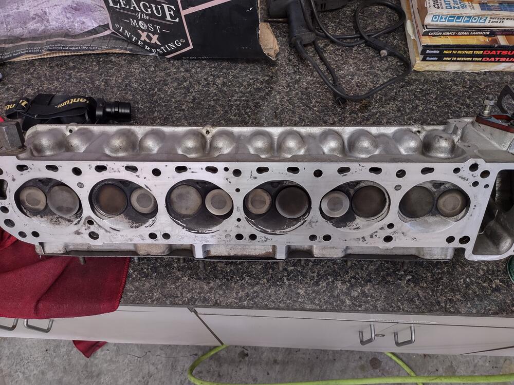
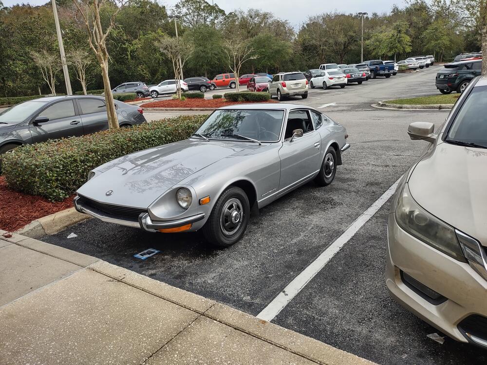
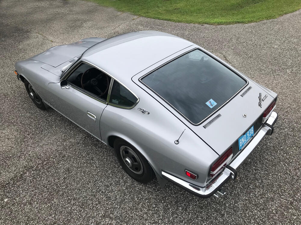
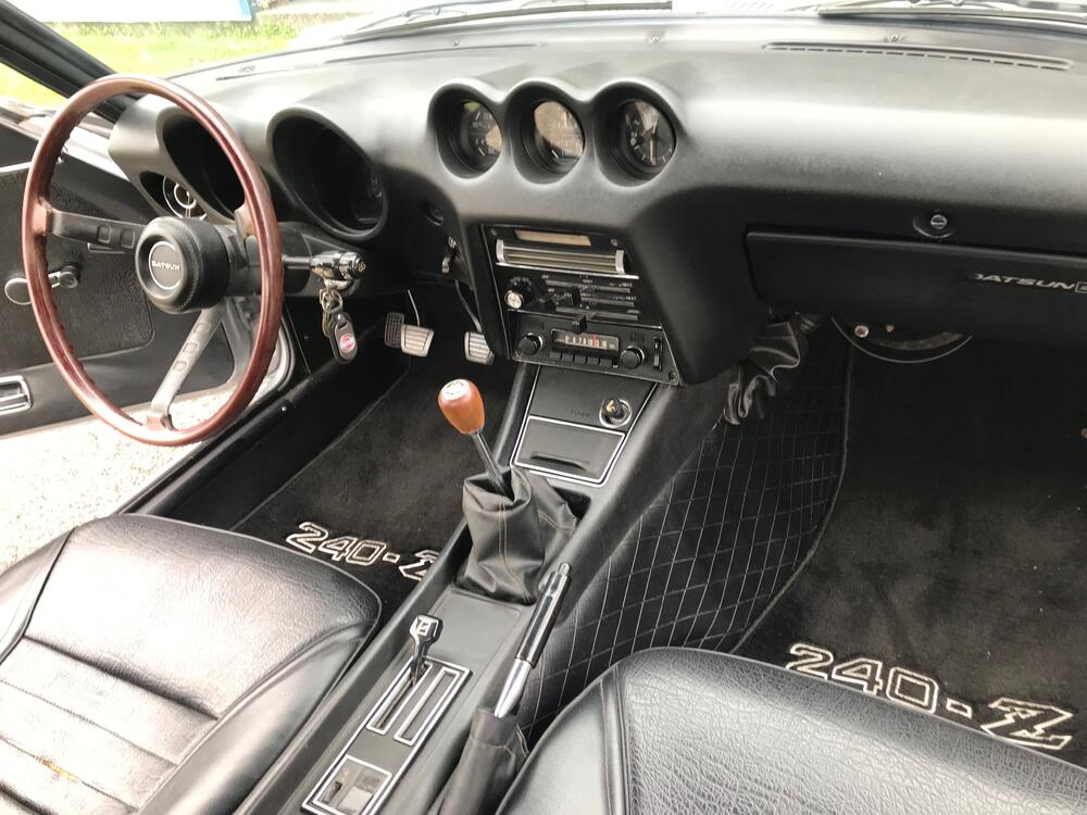
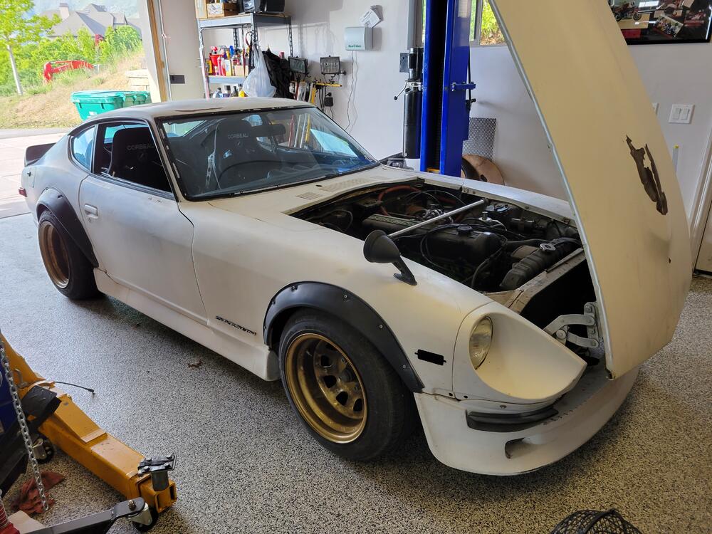
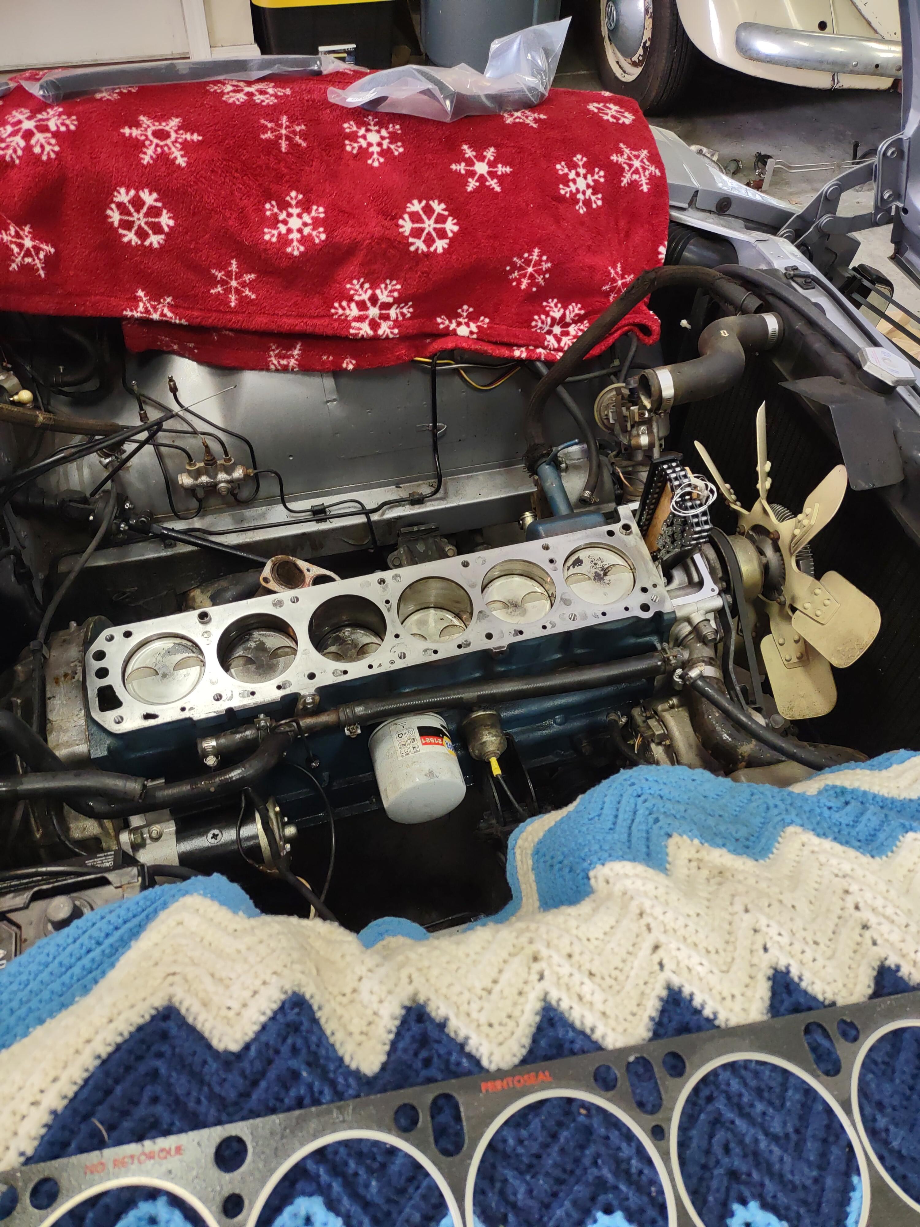
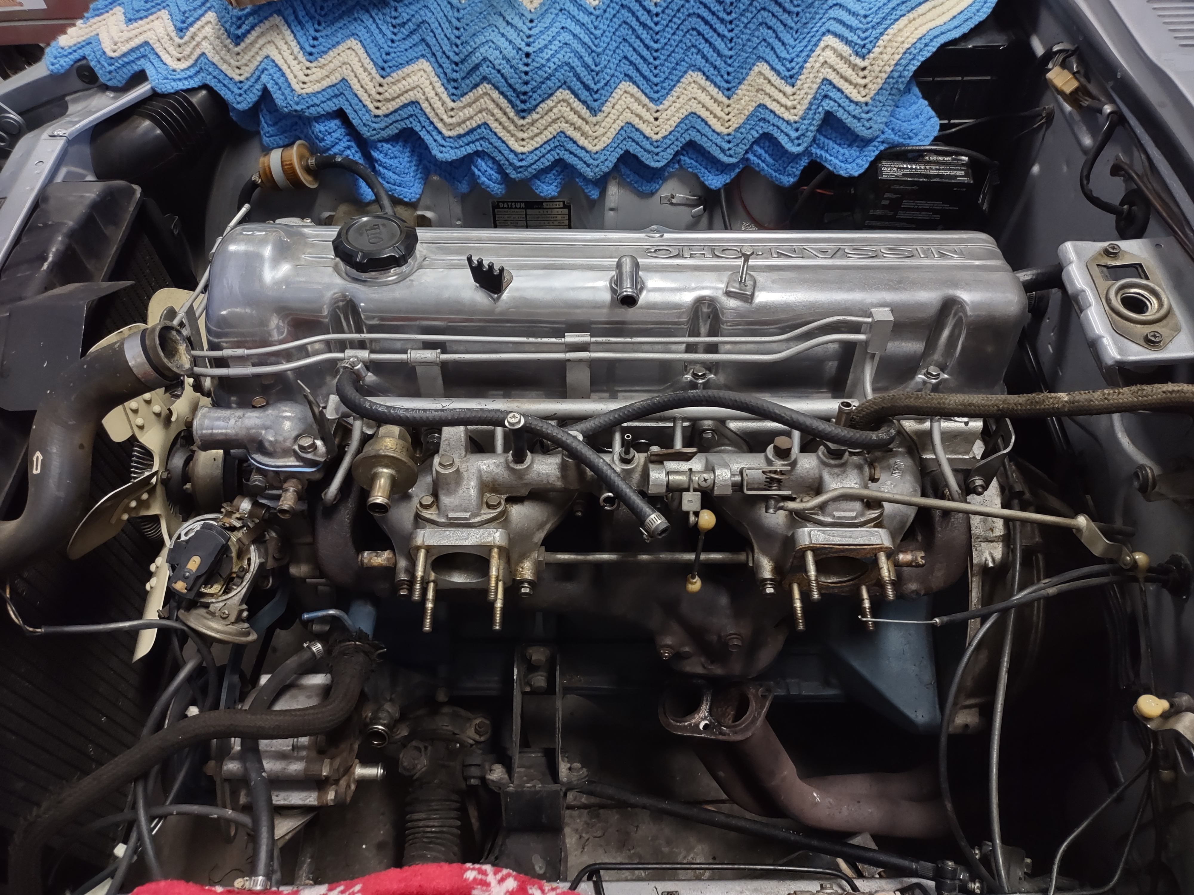
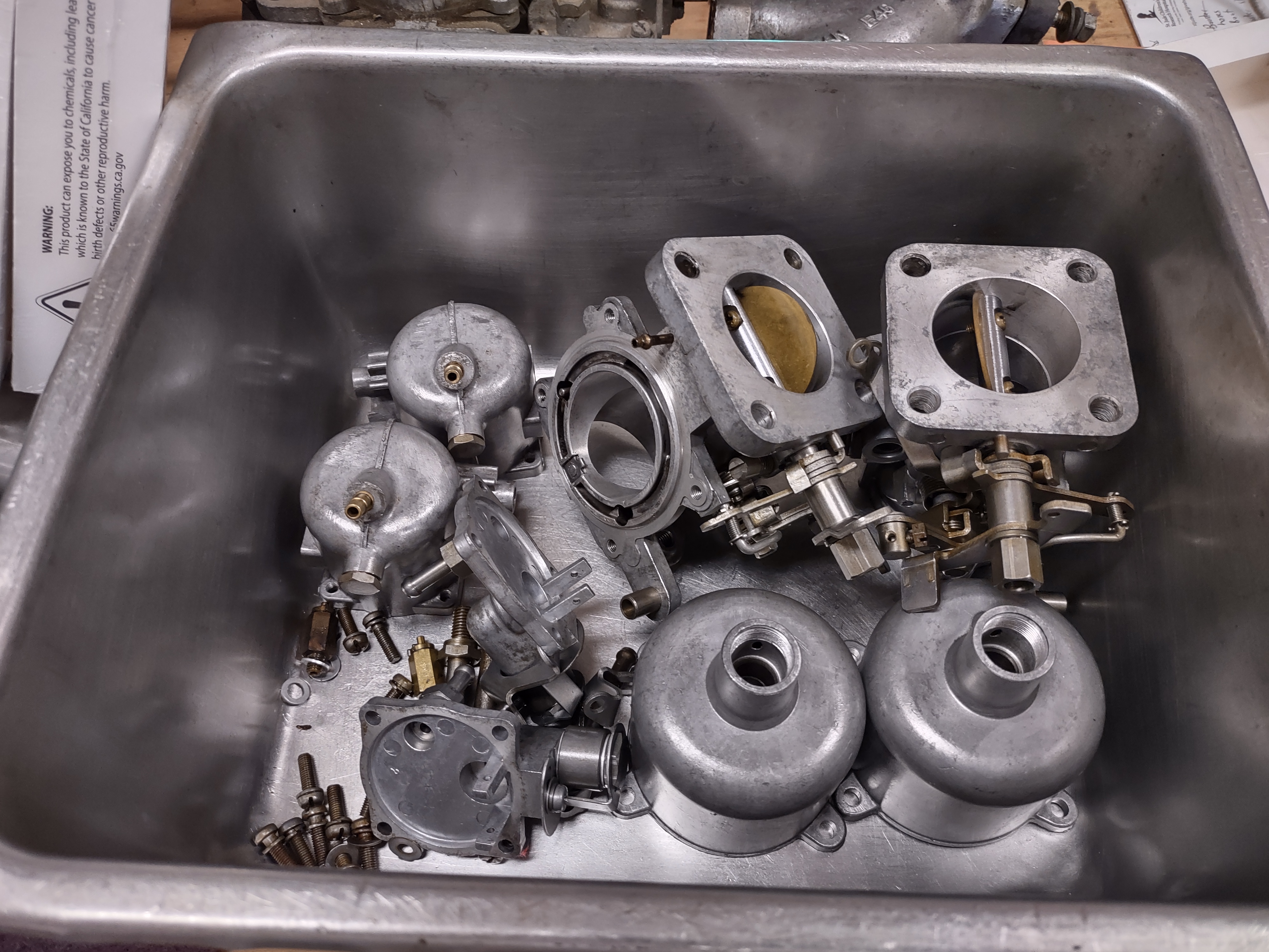
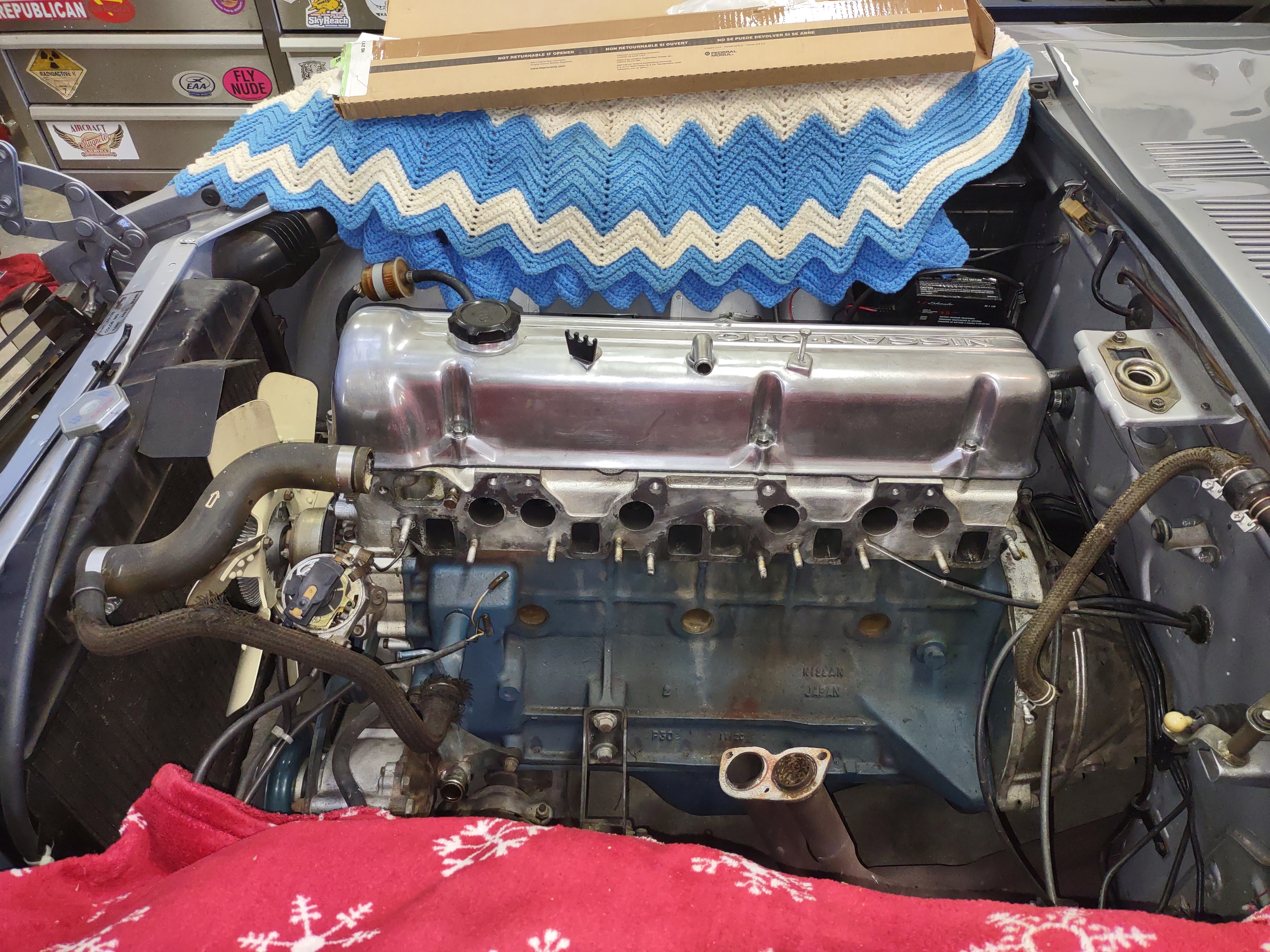
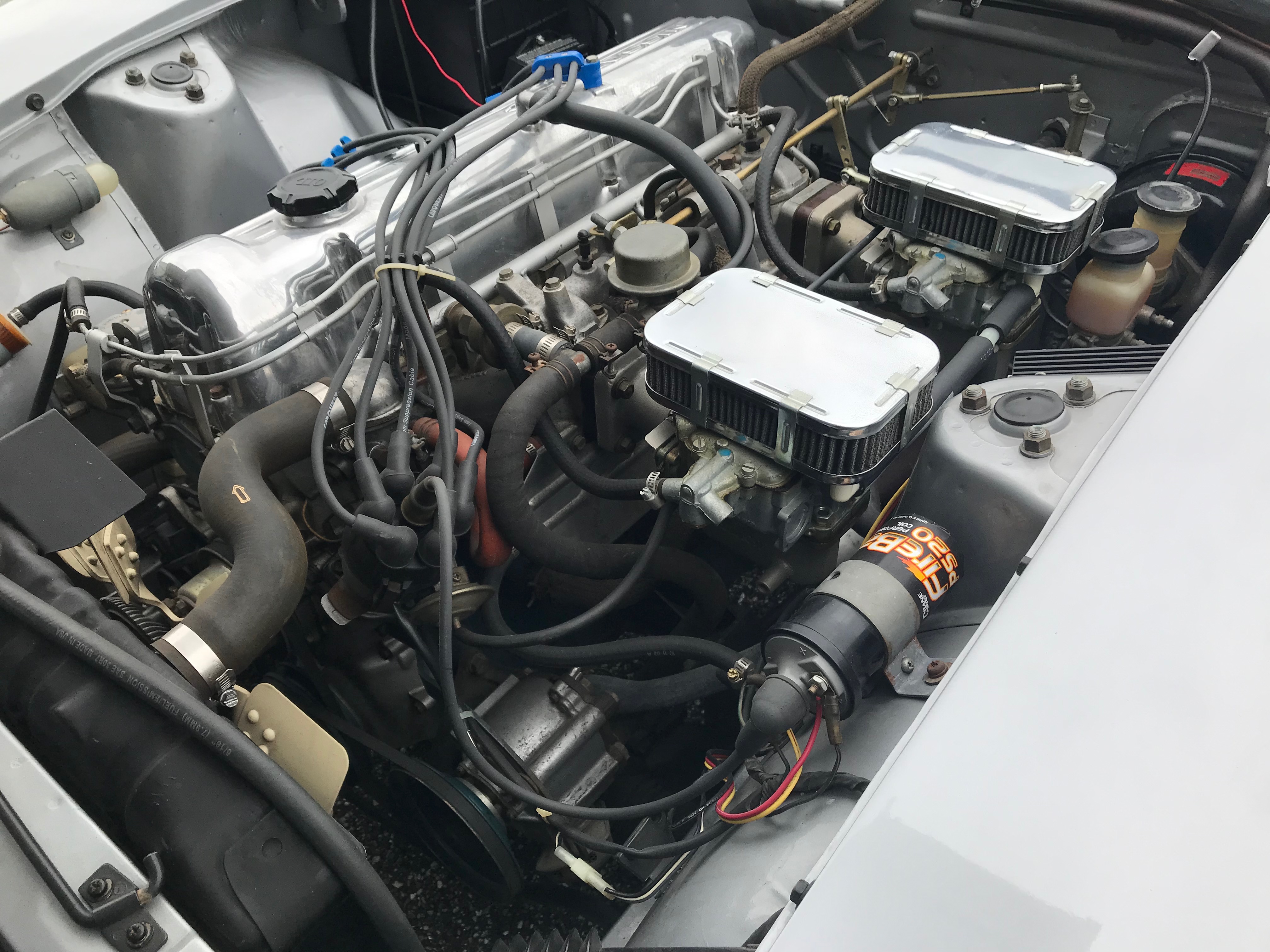
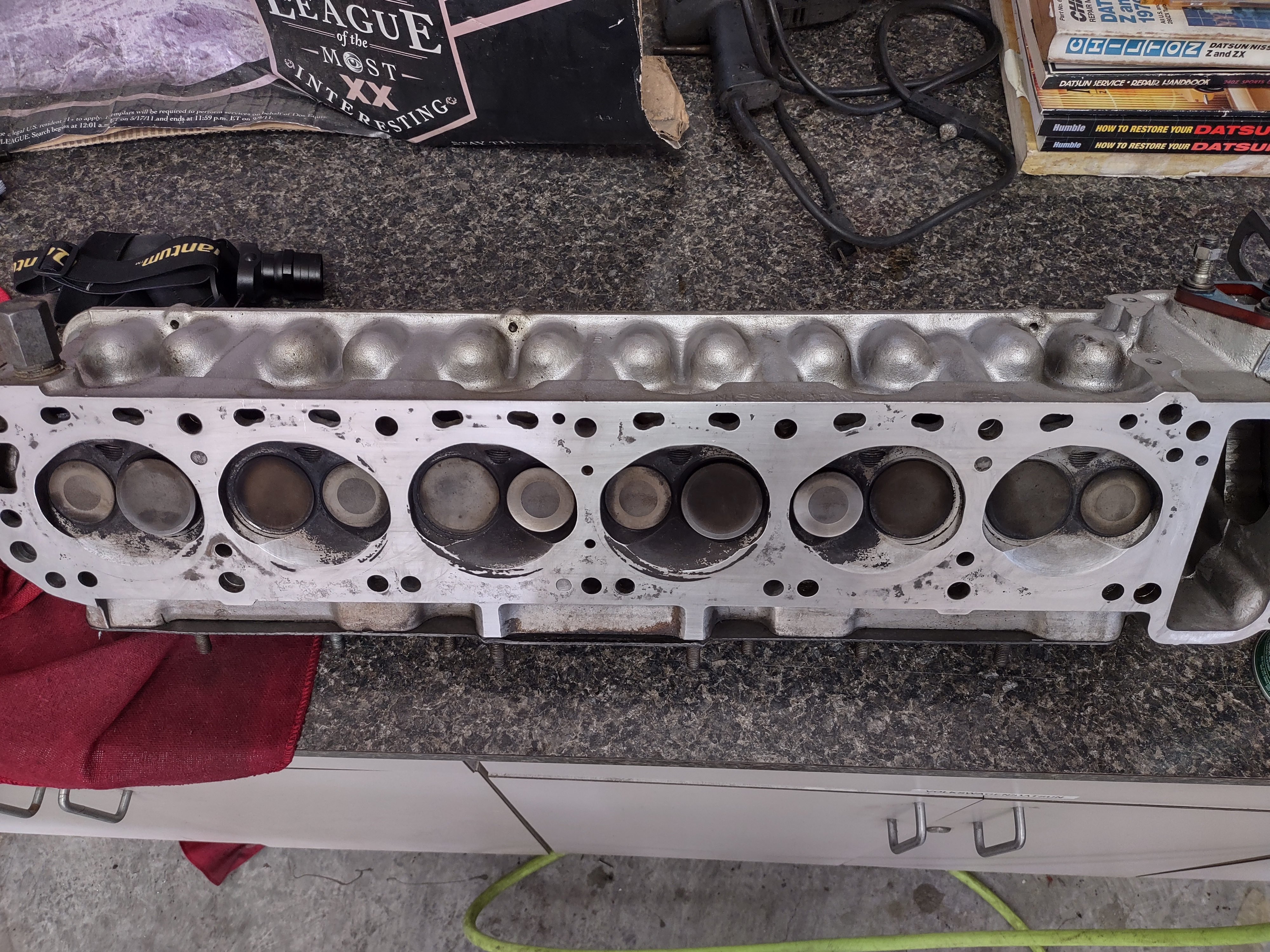
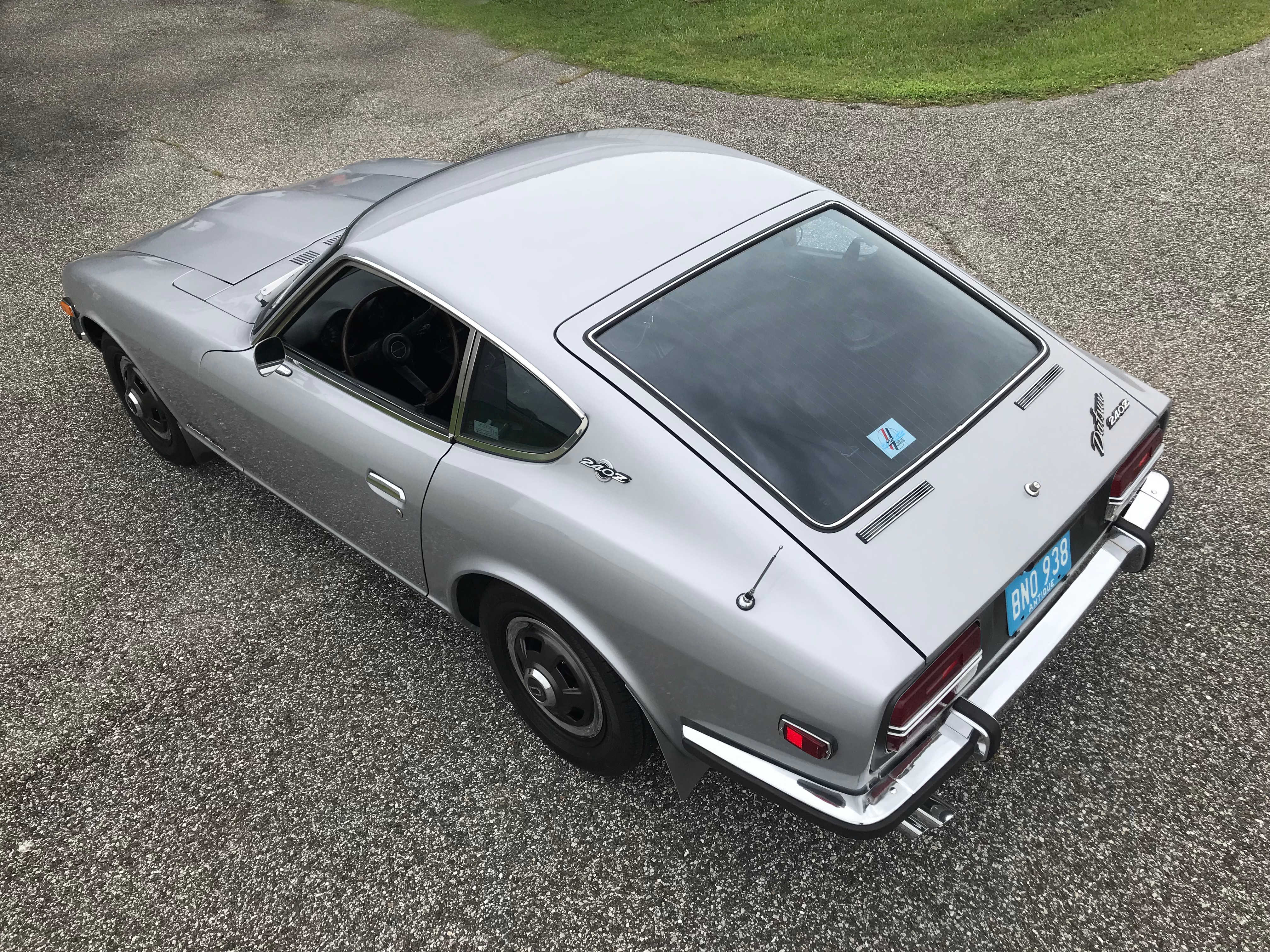
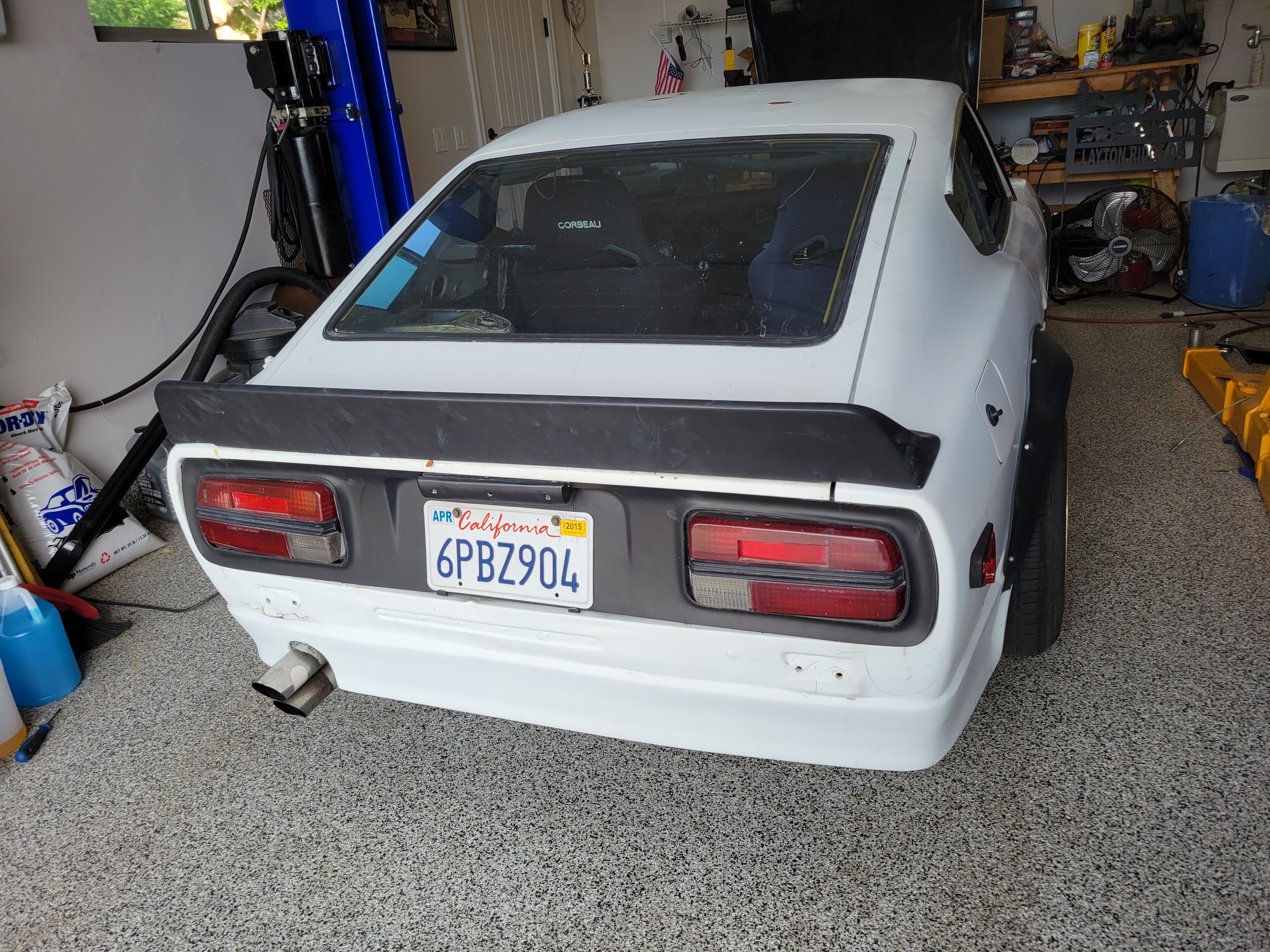
My 1971 series 1 car needed a head gasket (leaking because I think the head wasnt torqued correctly), and also reinstalled original carbs after overhauling and associated emissions equipment back to stock. Engine was rebuilt and has about 2000 miles on it from the original owner a while back. Head and block are straight. Car sat for about 18 years without being driven. Needed new brake lines and a brake booster. I had the brake booster overhauled at Power Brake Booster in Oregon, they did a great job. This is an original car with 48,000 miles documented. Only "restoration" work completed on the car was paint and body. All original interior. No leaks and runs great.

.thumb.jpg.52ab588112d350b142955ba6002d94c4.jpg)
 2 points
 -
2 pointsJust wanted to add some noise to the conversation, this dude makes some really nice interiors for other Datsuns. Wonder what two completely new door cards would cost, and how close they are to OEM. https://www.instagram.com/tree_ausawa/2 points
-
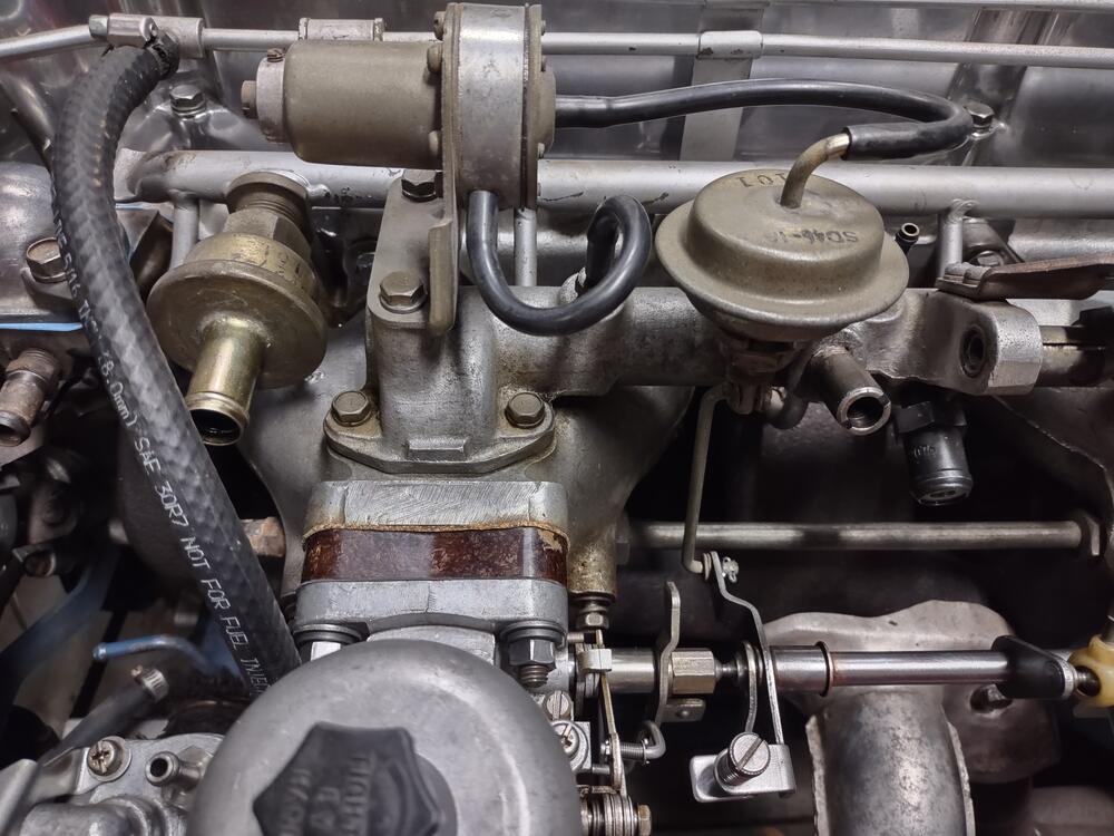
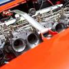
2 pointsDo nothing until you set, and confirm that you have set the fuel level in the float chambers properly. Any changes to float level alter all the jets that you land on using your wide band 02. If you have incorrect fuel level, and you correct it after your tuning with the wideband 02, you will surely have to tune for jetting again. Mikunis are very sensitive to fuel pressure also. Look up the recommended value range in psi. I believe it is 3.5 psi. Use a quality fuel pressure regulator to ensure steady and regulated pressure. If I recall correctly, idle and cruise are going to be running off of the same jets - these are the pilot jets. Setting idle mixture screws appropriately is critical to the selection of those pilot jets. Adjusting the amount that the idle mixture screws are turned in or out will cause differences with any given pilot jets. Set them at 1 and a 1/4 out... to 1 and 1/2 out from full in. Do not go further out than that. And leave them alone after doing so. Later, you can tweak them between that 1.25 to 1.5 to fine tune AFR at idle, but set that thought aside for now. Also, be very careful when bottoming them out. Note (write down or draw) screw head slot alignment... or "clocking", for each screw on each bore. That way, you won't have to repeatedly bottom them out in the carburetors because you forgot where you were while turning them. The idle adjustment screws are fragile, and easily damaged. The screws should have perfectly shaped tapers, not any wear marks or indentations in them where the taper seats against the carburetor bodies. Next, adjust the throttle stop, idle speed screws. You need the throttle flaps cracked open enough to get the car to idle. If you have a lumpy cam, do yourself a favor and set idle to at least 1200 rpm for initial idle and cruise tuning. Start the car. Adjust throttle stop screws to get the car to idle at 1200 rpm. Check air flow across the carbs. Sync at idle speed by adjusting the throttle stop screws per carb. I won't go into ignition timing here, but make sure your ignition time is set properly - static and dynamic. Once the car is idling at the desired rpm and carbs are in sync, swap pilot jets until you get 14 to 15.5 for the air fuel ratio. You can tweak idle mixture screws between the 1.25 and 1.5 range and watch what that does to AFR at idle. From here the car should be drivable. Next, you need to determine appropriate mains and air correction jets as well as accelerator pump jets. When determining all of those, keep in mind they all kind of are interrelated. If you are super fat/rich on mains, the accel pump will be impacted as well. Messing with air correction before getting the mains close is a waste of time. Same with the accel pump jets. Oh, and use the middle hole on the pump lever rods. Don't mess with the other holes in the rod. I recommend avoiding wide open throttle for a while. Instead, I believe the Mikuni manual indicates that the main circuits don't come into play until throttle openings exceed 20 percent. I recommend backing out the throttle stop (on the floor of the car) to give you max 80% throttle - maybe try to fab something to give you near 60 percent. When cruising, ease to your 60 percent throttle (pedal against your floor stop modification - allowing you to hit a consistent throttle position repeatedly for tuning) and record runs (if your wide band has that ability) for examining after the fact. Get 60 percent throttle and record or observe AFR from around 3k through 5k rev range (at 60% throttle). You are looking for steady state of 12.8 to 13 or so AFR while the main circuit is engaged (60 percent throttle should guarantee that). After you get the target AFR for 60 percent throttle, extend the rev range to whatever you max engine revs are, but use the same throttle opening percent. If AFR drops (richer) as highest revs are approached, go bigger on air correctors. Again, I find that the mains and air correctors are interrelated. For example, if you change the air correctors a large amount, it may well change your "baseline" you had with the mains that were achieving the target AFR range. Keep this in mind if you find you are having to make large changes to air correction to get where you need to be AFR-wise at the last 1000 rpm of the range. Do not drill Mikuni jets. They are sized due to their flow. It is possible that the orifices will differ in size for a specified jet number. Do not alter. Again, they are sized for flow, so if the orifice is bigger on one of same numbered jet, it will flow the same as o,ne of the same number but with a smaller orifice.2 points
-
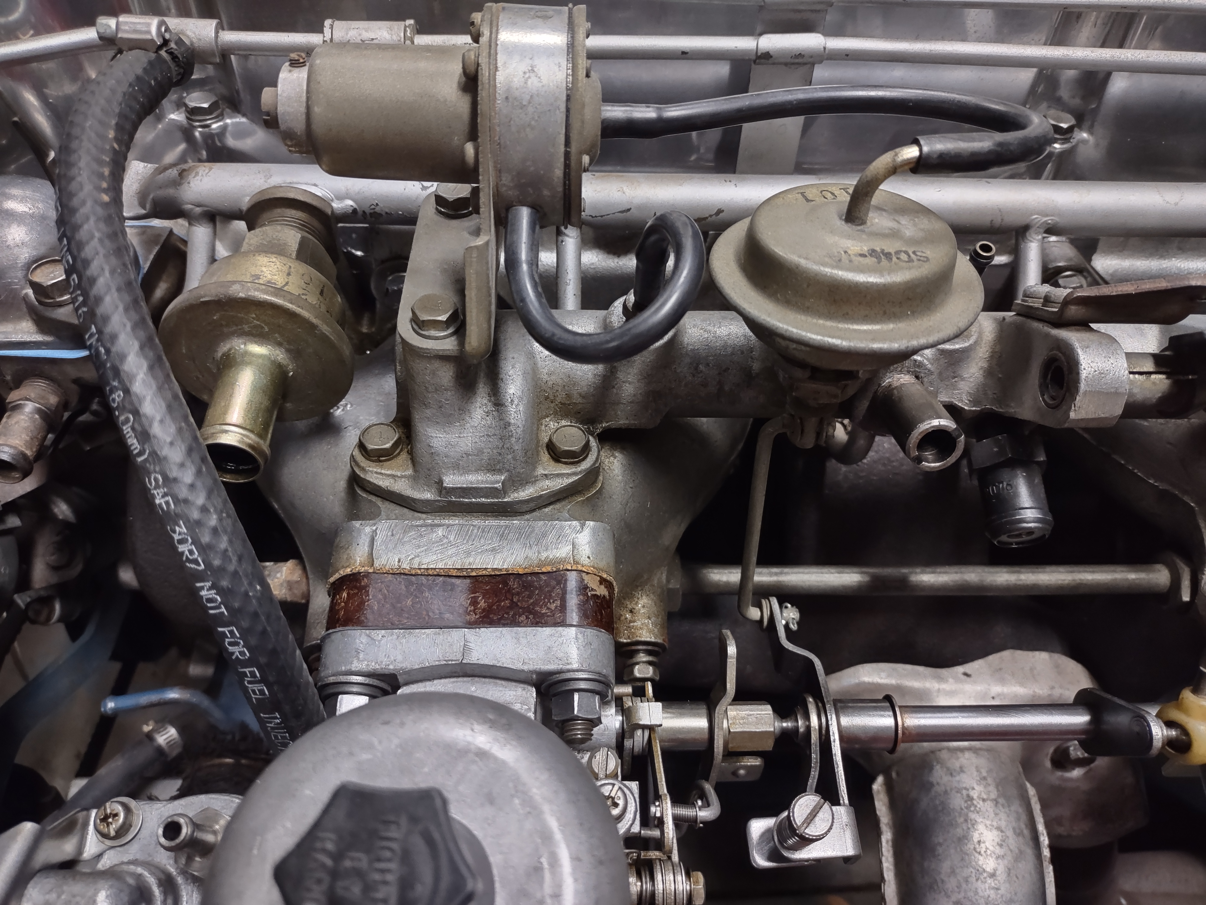
2 pointsI wrapped them around. I wanted to see where specifically fuel was leaking from the banjo nuts, mostly for my understanding. New crush washers took care of the leak. The tape has since been removed.2 points
-
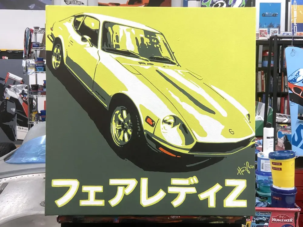
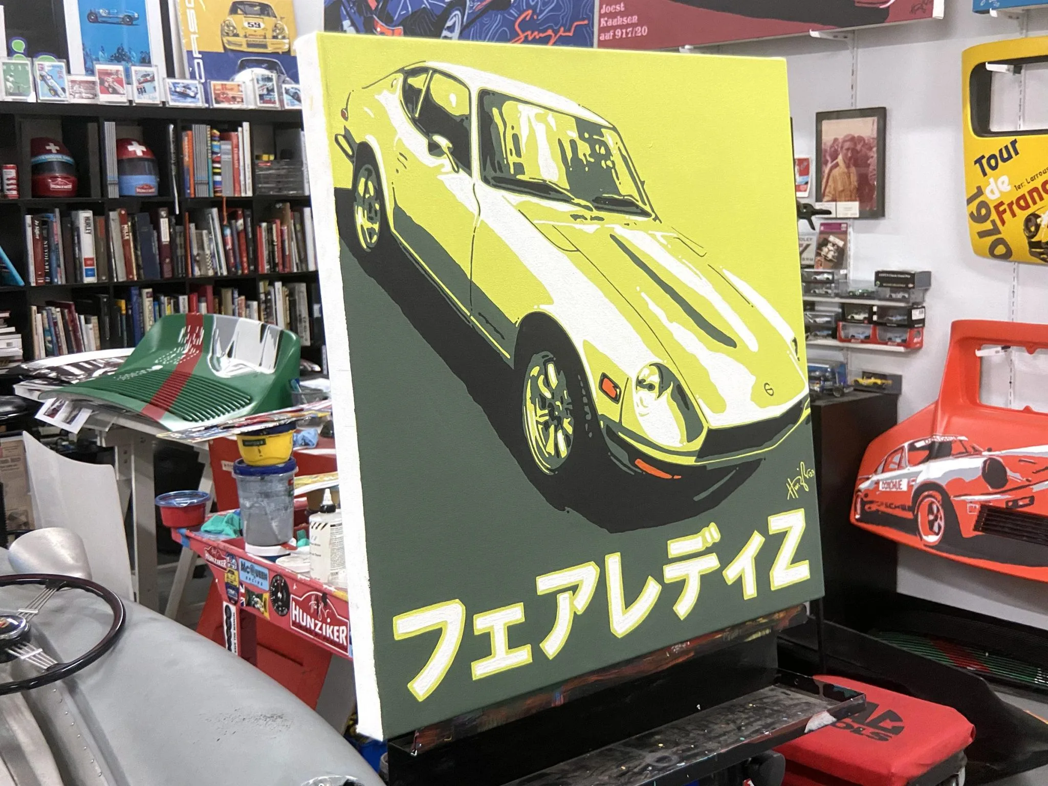
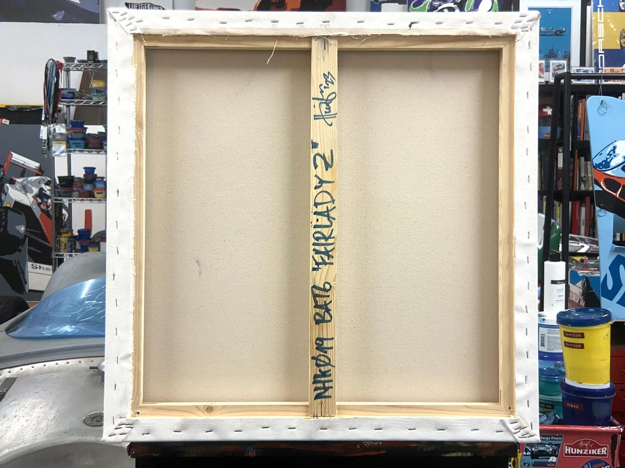
Z artwork on BAT. Six piece collection auction for charity. No Reserve: Six-Piece Collection of Original Paintings by Nicolas Hunziker for Charity for sale on BaT Auctions - ending May 17 (Lot #107,455) | Bring a Trailer No way I can afford to bid but I DID but a T-shirt.

 2 points
 -
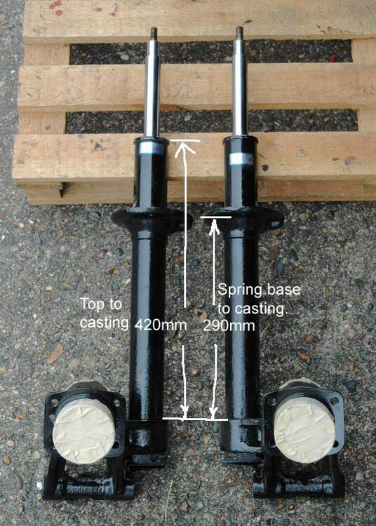
In my black museum of leftover Works rally parts, I have a front strut that came to me described as a 'Monte Carlo' tarmac setting item. It carries Works part number Dymo tape labels 'Y0901-54302' and has the proper Works type Halda drive take-off. I will dig it out of storage and take some measurements.
 2 points
 -
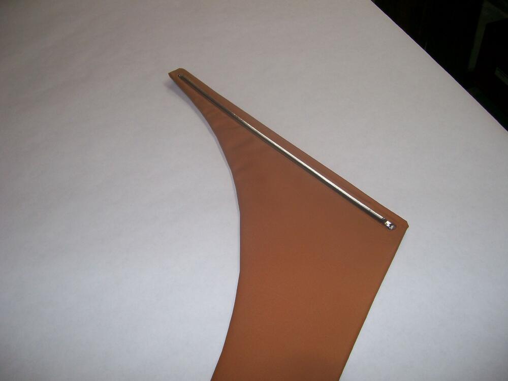
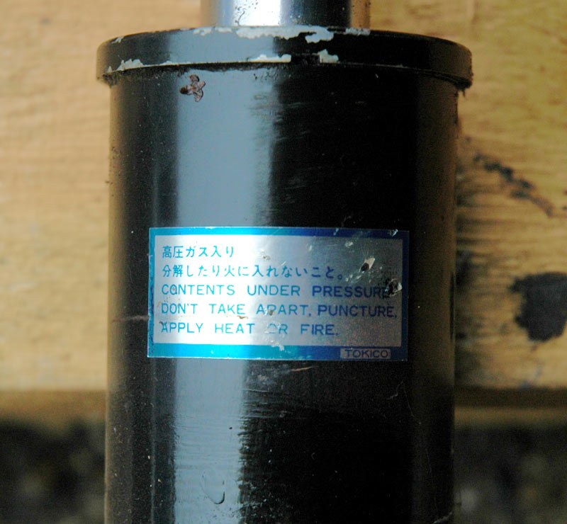
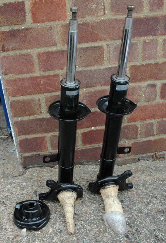
I've been away on a trip to Japan, so a little late answering. Sorry. The 54302/54302/54010 etc etc prefixes on the stock & option strut components simply identify the part according to the Nissan parts numbering system, where 54 denotes front suspension section, 000 up denotes front springs, 200 up spring mounting parts, 300 up suspension crossmembers & 400 up suspension assembly parts. The Competition Department in Japan used these as suffixes in their unique (Works) part numbers, so I guess it makes sense that they correspond somewhat. I'm not sure that the E7220 Rally Option struts and springs are going to be much use as reference for you. I own a set and they have looooong tubes and looooong springs, putting the car up at 'Safari' type ride heights for max travel and ground clearance. They are oil-filled and also gas-charged, but I'd say they are a step below the Works type parts in sophistication and build quality. They were probably OK for a 'Clubman' type rally car in period, but my friend Kevin Bristow used them on his car 'OMT' (prepped in period by Old Woking Service Station) and found they they soon overheated on rough stages. Some photos of my set for reference:

 2 points
 -
2 pointsWell if this works I’ll follow suit because my car smells of exhaust in the cabin pretty bad . I’m sure I’m getting mild carbon monoxide poisoning to some degree. I do have an extra gas mask from when I was in the military maybe I can just drive around with that on the meantime [emoji23][emoji23][emoji23]2 points
-
That's in USD. @zKars posted the CAD price.1 point
-
Yes, please! Knowing the spring perch height, and overall strut height of the Tarmac strut casings would be very useful. If they are identical measurements to mine, or even very close, that would lead credence towards re-using my casings with shorter springs to create the proper ride height.1 point
-
Thanks for posting this Jim. I just went onto there site to look at their rear bumper and asked a few question using their on-line chat. They were very helpful and even sent me a picture of their rear bumper installed when I asked if the center section has that slight curve to match the body. Here's the pic. I will be placing an order soon. Thanks again.1 point
-
When you call ask for Max. Good people.1 point
-
1 pointThank you for that imaginative and detailed report on reproducing the door panel chrome strip. I might just do that. BTW, I've contacted the owner of Treeaswa Retrocar Co., Ltd. in Thailand and will be mailing him a sample of the light blue vinyl fabric that I've chosen for the soft bits of my interior. I'm sure he will be able to work it as it was designed to be used in boat upholstery. I've also asked him to quote on the parts I need produced. Between that and the cost of shipping stuff from the U.S. to Thailand and back, I'm not sure it will be competitive with what a local auto upholstery shop would charge me but you never know until you ask and do your due diligence.1 point
-
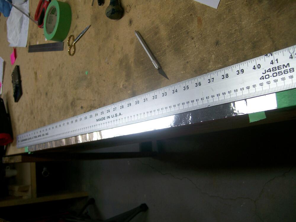
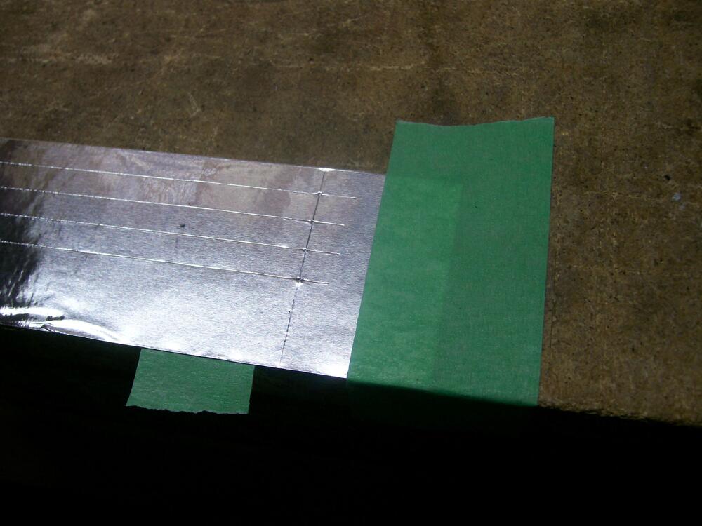
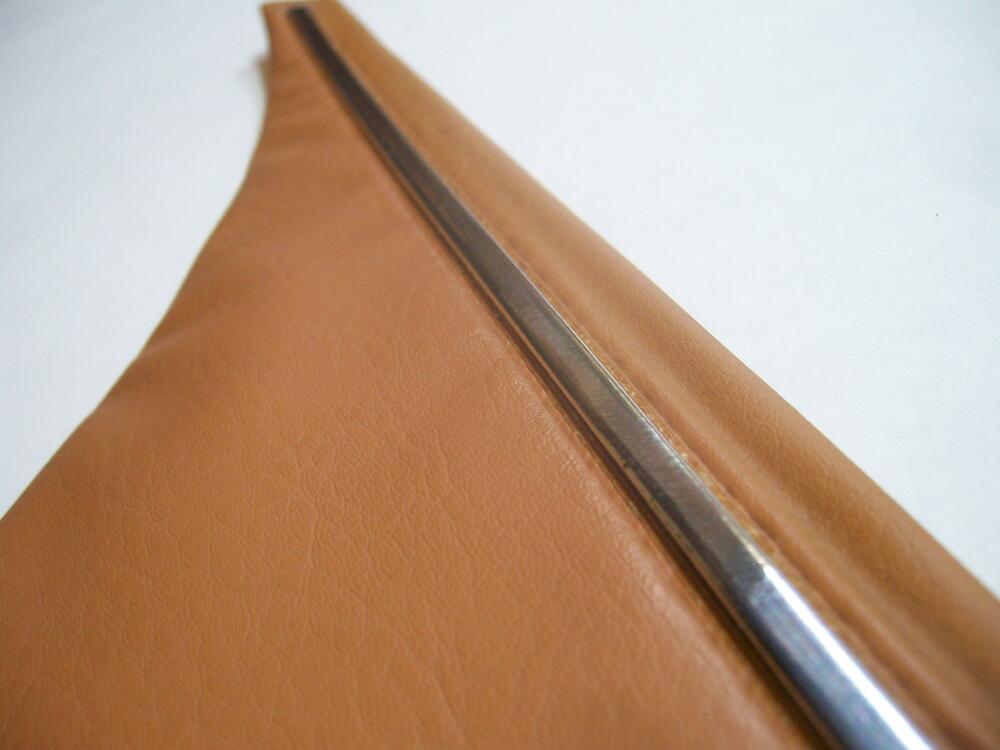
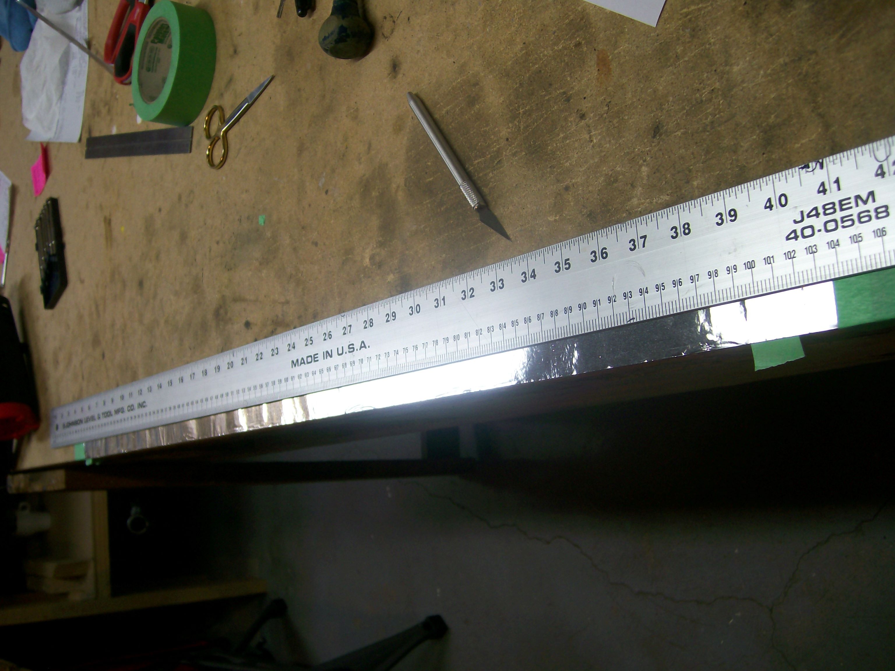
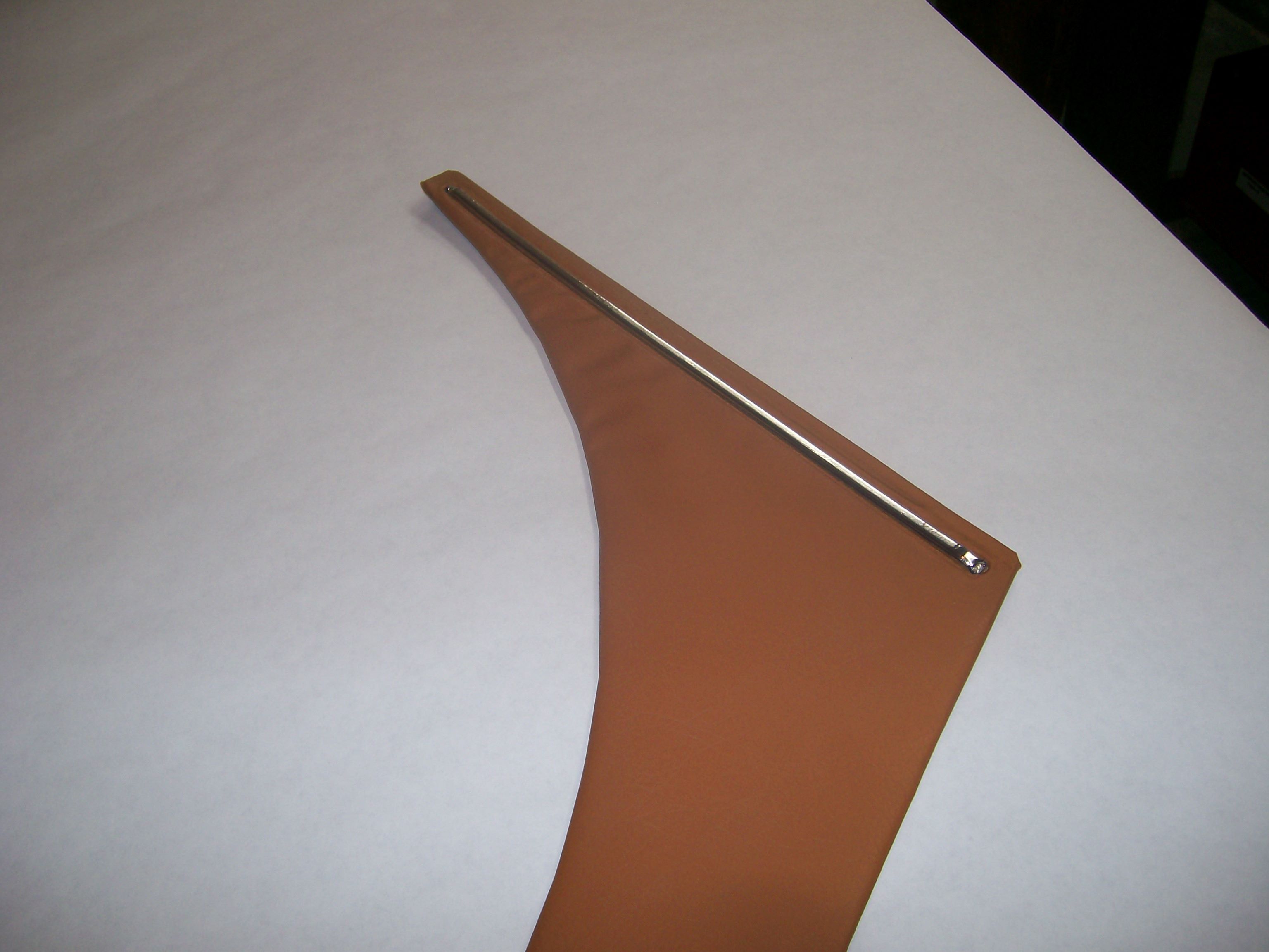
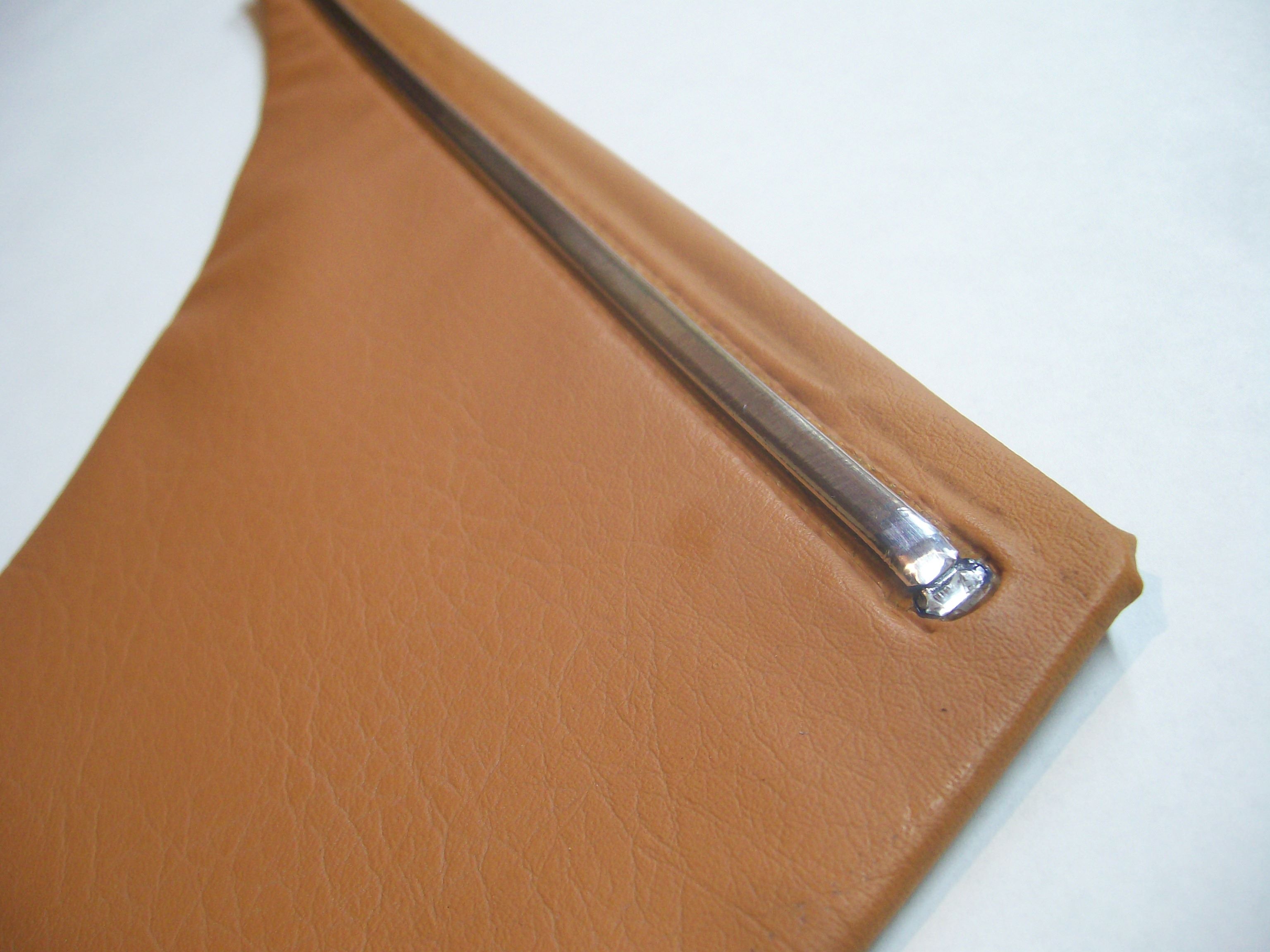
1 pointFor your consideration: HVAC duct-sealing foil tape (adhesive backing) can, with care and patience, be used to replace the chrome film. The result has a finish that's almost indistinguishable from the original. I used this foil to restore my door cards and rear kick panels. Five years later, the tape remains securely in place. Steps: Leave the trim strip in place, but peel off the 'chrome' layer. It comes off as a thin film and you should be able to remove 100% of it without needing to use chemicals. Left behind will be the blue-coloured plastic strip. It has a 'D' cross-section. Measure the perimeter of that cross-section by shaping a piece of aluminum foil over the surface and marking the base of the 'D' on each side with an awl or straight pin. Flatten out the foil and take your measurement. I measured it at 9mm for the rear kick panel. I'm not sure whether it was the same for the door card accent strip. Cut a length of HVAC duct-sealing foil that's about 6" slightly longer than the door trim strip. Secure it to a flat surface, shiny side up, using regular 'duct tape' at each end. Mark off several strips, using the 'D' perimeter measurement to define the width of each strip. Using a long straight edge and a utility knife (with a fresh blade), cut at least full-length 6 strips (you eventually only need two, but you'll probably ruin at least two at the start as you practice stripping off the backing sheet and then applying to the door strip). For each lengthwise cut, work from the inboard edge of the widthwise duct tape at one end to the similar point at the other end. Then, after making your six lengthwise cuts, use a shorter straight edge to cut widthwise at each end. Tip: It helps if you clamp the long straight edge to the table/bench top, so that it can't move while you're making each long cut. Clean the surface of the blue plastic trim strip thoroughly. I used denatured alcohol. It's particularly important to get the top and bottom parts of the 'D' clean (where the strip meets the door trim vinyl). As noted, it takes a bit of practice to figure out how to pull the backing strip off the aluminum foil strip without putting a kink in the foil and/or having the foil accidentally bond to some unintended surface before you have a chance to start laying it down on the intended target (i.e. door card's blue plastic strip). It also takes a steady hand to keep the tape properly centered on the blue plastic strip as you lay it into place along the length of the plastic strip. The application technique is to lightly lay the foil onto the crown of the D. Press it into place at the front end of the plastic strip, then align while gradually lowering the full length of the foil down into place. It may take a few tries to get this right. Unfortunately, every failed attempt will ruin the foil, so you'll need to use a new strip for your next attempt. Once you get a good result, the next step is to cut the excess off at the front and rear ends of the foil. You'll need to judge the position of these end trim cuts so that, once pressed down, the cut end of the foil will align with the end of the blue plastic strip. Getting an acceptable result here requires a little additional work because the end of the blue plastic strip is rounded. The foil will not stretch to meet this contour. The only way to avoid a crinkled surface is to make two short lengthwise cuts so that the foil is now divided into three short segments. Eventually (but not now), you'll be able to press the center part down first, and then press the top and bottom segments into place. There'll be a slight overlap. Returning to the main job, your foil strip at this point is lying flat along the length of the blue plastic strip, touching only the crown of the 'D'. You now start working the foil down over the 'D' contour. Use a soft cloth rub lengthwise, gradually working the tape down over the 'D' contour. To avoid 'bunching', work from the center out to each end, rather than from front to rear. Work from the crown of the 'D' outwards, alternating from the upper half to the lower half. I think you'll be very pleased with the final result. My only caveat for this technique is that I haven't tested the effectiveness of the foil adhesive under extreme temperatures (e.g. car parked outdoors in the summer with the windows up). If you're concerned about this and think you know of a better adhesive, you could always try gluing chrome mylar film over the blue plastic trim strip. Personally, I like the foil because it's metal and actually bends to into shape over the 'D' contour, meaning that there's very little residual force trying to lift the edges. At extreme temps, the adhesive may temporarily get a bit gooey (technical term), but I don't think the foil will lift unless it's disturbed by the side of your arm. I take some consolation from the fact that this foil is designed to be reliable for use on air distribution ducts that carry both cooled and heated air.1 point
-
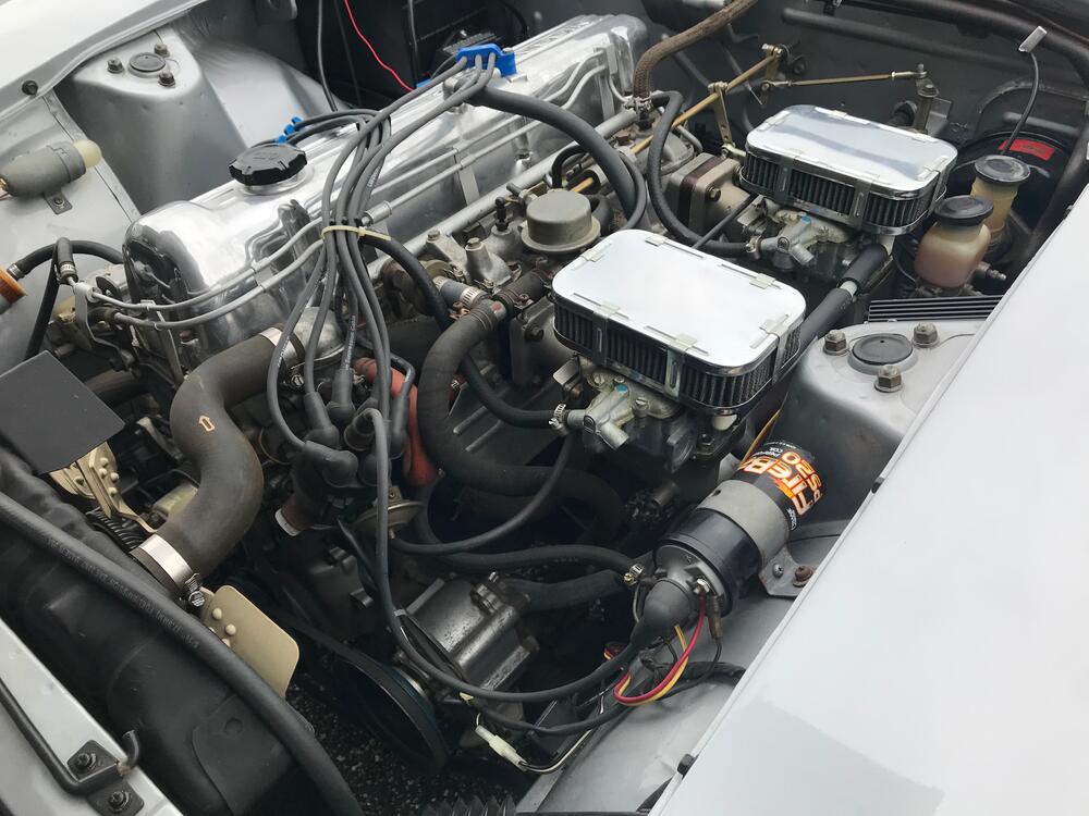
1 pointThanks @inline6 This is super helpful. In post #295 you can see the approach I took which is a bit different. First note being the idle mixture screws were turned out 2-2.5 turns which is double your recommendation. I will need to see where I landed at and if I need to change my pilots. Is there a reason why 2 turns out is too much? I was able to get my AFR gauge temporarily installed enough to check my idle AFR. I'm glad I picked this up because I was LEAN. At idle I was in the 17s. It makes sense now, but I assumed that I would be rich just because I smelt fuel. But looking back now, running lean can have poor combustion where not all the fuel is vaporized. Wasn't able to drive the car since its been raining all day so that'll be for another day. In the meantime I'll check my idle mixture screws and adjust my pilots if needed.1 point
-
1 pointI did go on a test drive on the backroads by the house with the daughter. It’s nice that I don’t need earmuffs anymore when the car is running. IMG_8037.mov IMG_8036.mov1 point
-
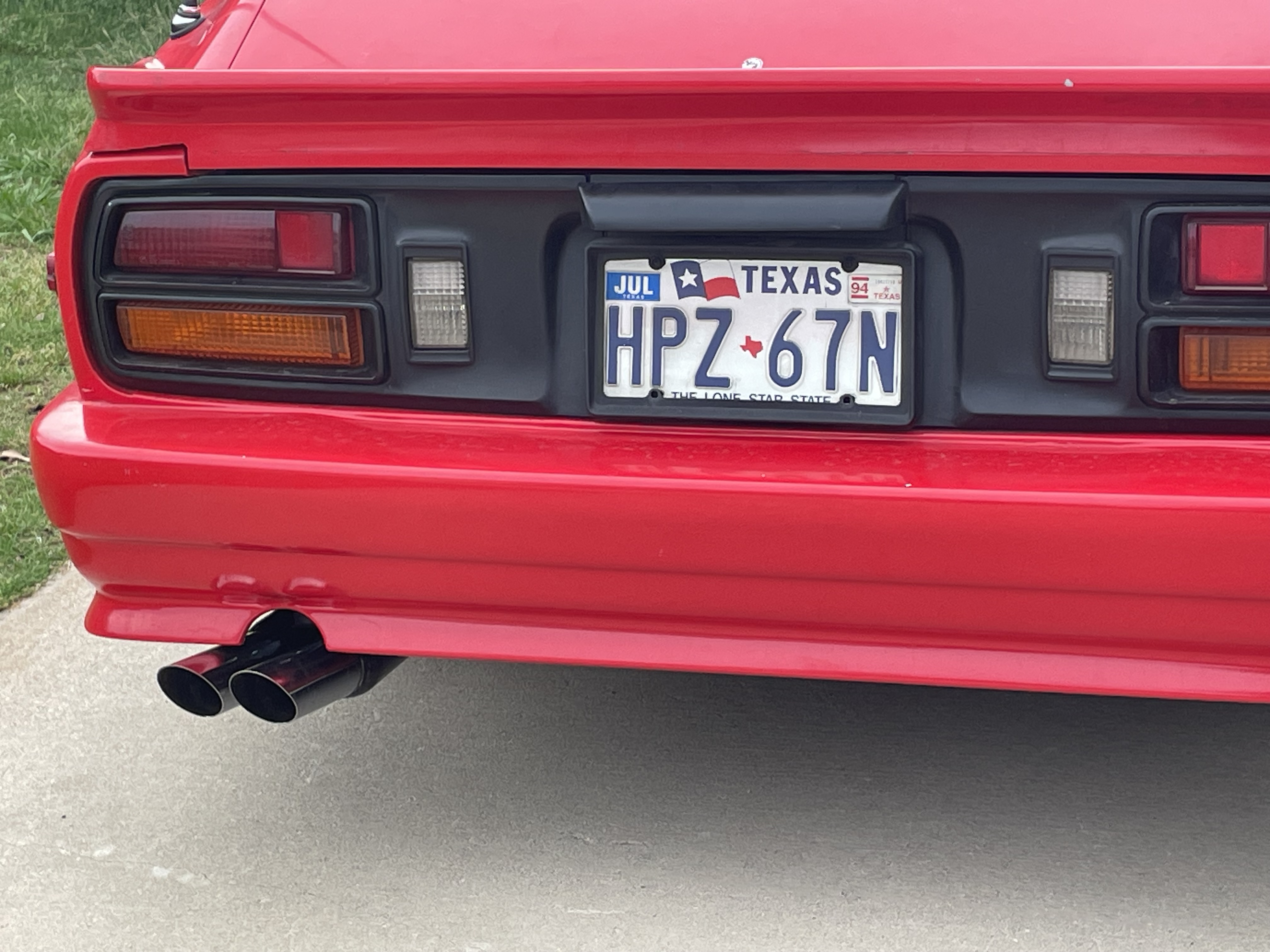
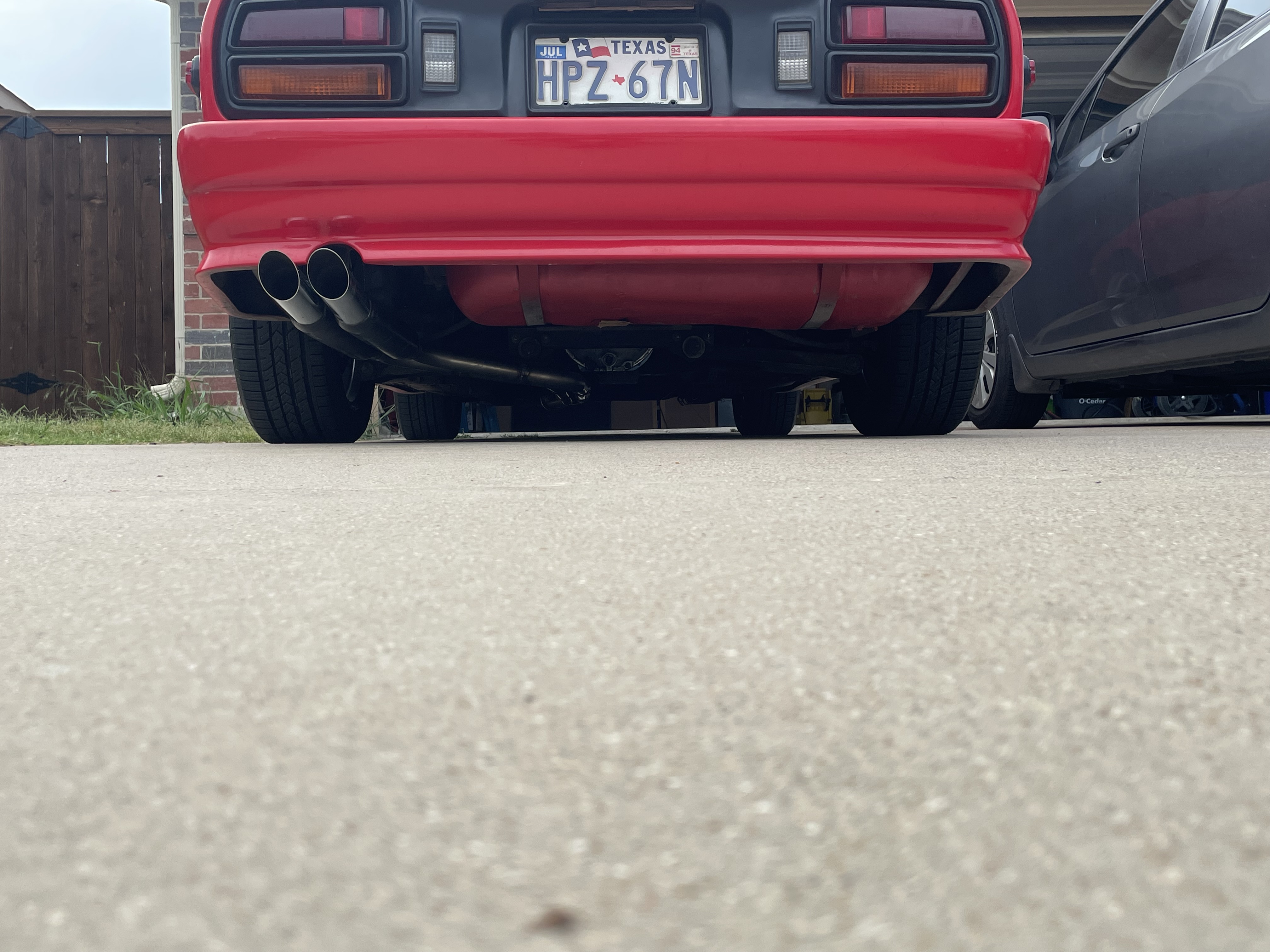
1 pointExhaust installed. I’ll have a fiberglass shop trim the rear bumper appropriately. My big concern is the exhaust scraping when leaving the driveway, my Z32 had that issue. No clearance issues with my current setup on the 280Z. Inspection for registration will be this weekend. A few items to fix: *cigarette lighter socket isn’t working, need to work. *carpet padding in final installation. *clean up interior *replace the mount for rear louvers (right side plastic broke, removed louvers until it’s replaced). IMG_8764.mov 70553628747__F813FE92-D1EE-47FE-91FE-2ED2B3752333.mov

 1 point
 -
Looks like they are no longer there. Search on z story Sean Dezeart and look at his posts.1 point
-
1 pointYou're welcome. I had nothing to lose cutting up that old door panel and I found it quite interesting to look into the methods of manufacture used 50+ years ago.1 point
-
1 pointThanks for those leads, AZ-240z. I shall definitely take a hard look at that option. And, CanTechZ, what can I say other than "WOW!" You went to a LOT of trouble to do that exploratory work and I truly appreciate it.1 point
-
Yeah, understood. If we can make this work they'll come to a great home! 😄1 point
-
1 pointThe OE cans are "thermal" - they use a bi-metal strip that heats and cools at differing rates depending on the flow of the electrical current. They usually operate more slowly at idle and then speed up as engine revs increase. The newer units are termed electro-mechanical, operate at a constant rate independent of the engine speed.1 point1 pointThat sounds like the seal 'n peel clear silicone sealer we ended up using1 point1 pointOK, in that case, if the chrome strip cannot be removed without its disfigurement or destruction, I might just buy two pieces of 3/16" x 3/16" x 36" 304 stainless bar stock from Grainger, cut them to length, radius two adjacent edges, polish them up and glue them in place. I'd use half-round but I can't find any that small. I might even be able to drill and tap the backside of those bars to accept jewelers screws coming through the metal plate. Sure, SS isn't chrome but because I'm going "custom" that won't make a difference.1 pointHad to take a break from the Z - I'm driving the X1/9 to Carlisle Import Show tomorrow, so yesterday I changed the oil & filter (been about 500 miles since the rebuild) and swapped out the wheels & tires for the new Federal 595's on Rota TBTs1 pointGot it running after 7 or so years. Found out it has an L28, coilovers and a 5 speed. Here we go.
 1 point


.jpg.737b5eb76e399d1a5dedf9168ee7ff8f.jpg)


Important Information
By using this site, you agree to our Privacy Policy and Guidelines. We have placed cookies on your device to help make this website better. You can adjust your cookie settings, otherwise we'll assume you're okay to continue.