CanTechZ
Community Member
-
Joined
-
Last visited
Everything posted by CanTechZ
-
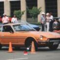
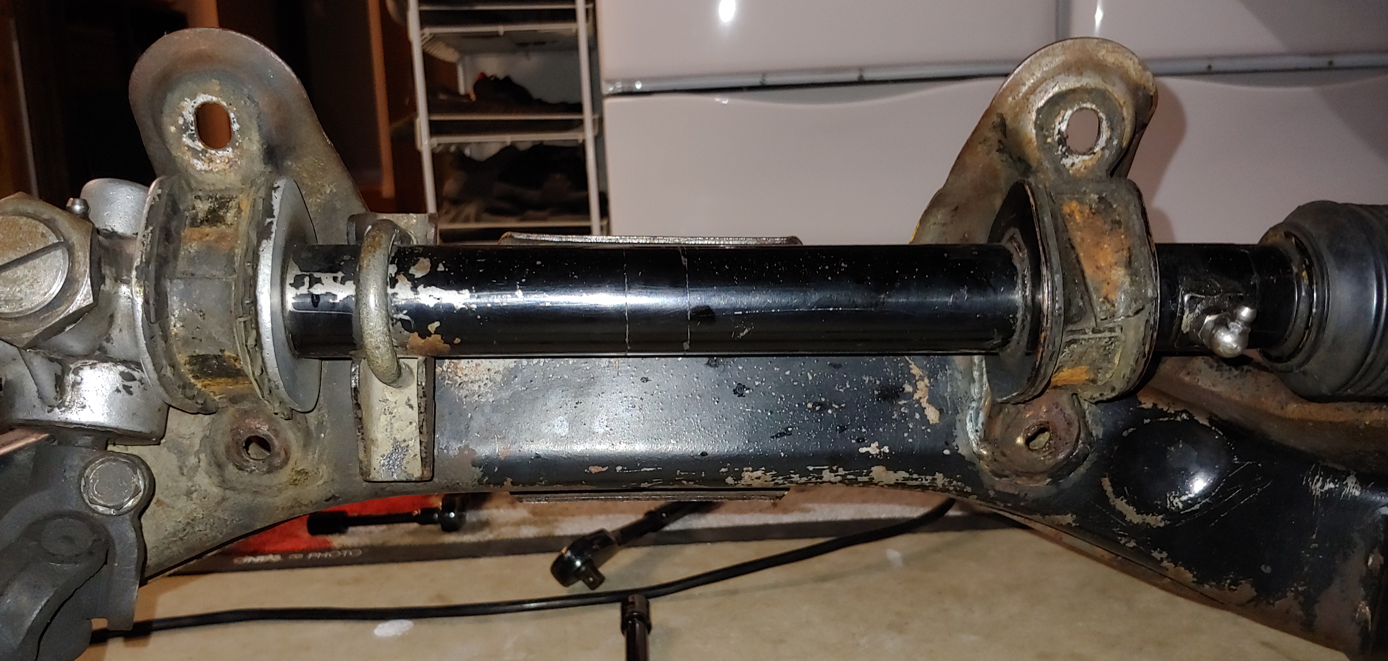
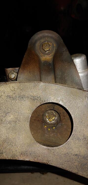
Yesterday I only removed the left clamp and it definitely had the 56° angle end at the front. In '05 I had a mechanic friend replace the rack boots while doing other service at his shop. I don't believe that he removed the complete rack. As of yesterday there were factory yellow paint marks showing. It still has the original bushings. I've owned the car for 43 years and this was the only work I've had done to the rack. However this morning I removed the the right side clamp and was surprised to find that it was installed opposite with the 50° angled end to the front, and 56° to the rear. Judging by the rust in the right clamp and twist of the bushing liner on the right side I think that it was backwards and the left was correct. Here is a picture showing both OE bushing on the rack with the clamps off, Regarding the angles on the crossmember, I have not removed the rack yet. But I have a crossmember from a 12/70 parts car and was able to check the angles on it. Both right and left are the same, the next picture is right side front angle that measure 38° The picture below is of the right side again, for the rear angle. The rear shape is different, it has angle change near the flat surface, I'm not sure how to describe that. The angle of the surface that is tangent to the curved clamping surface is approximately 32° Would probably need to measure the angles on the rack as well to review this in the context of an assembly to confirm which way is correct for the clamps.


-
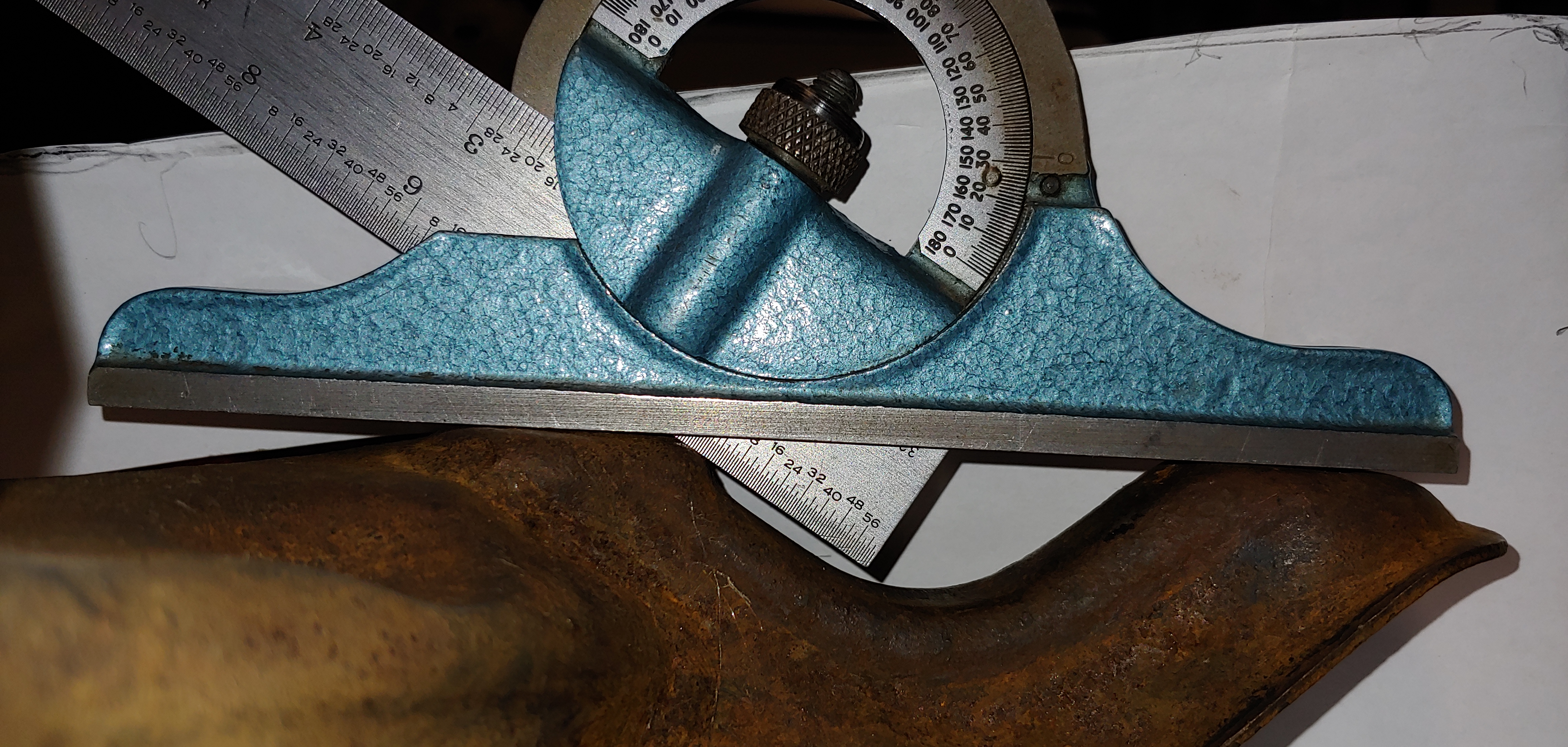
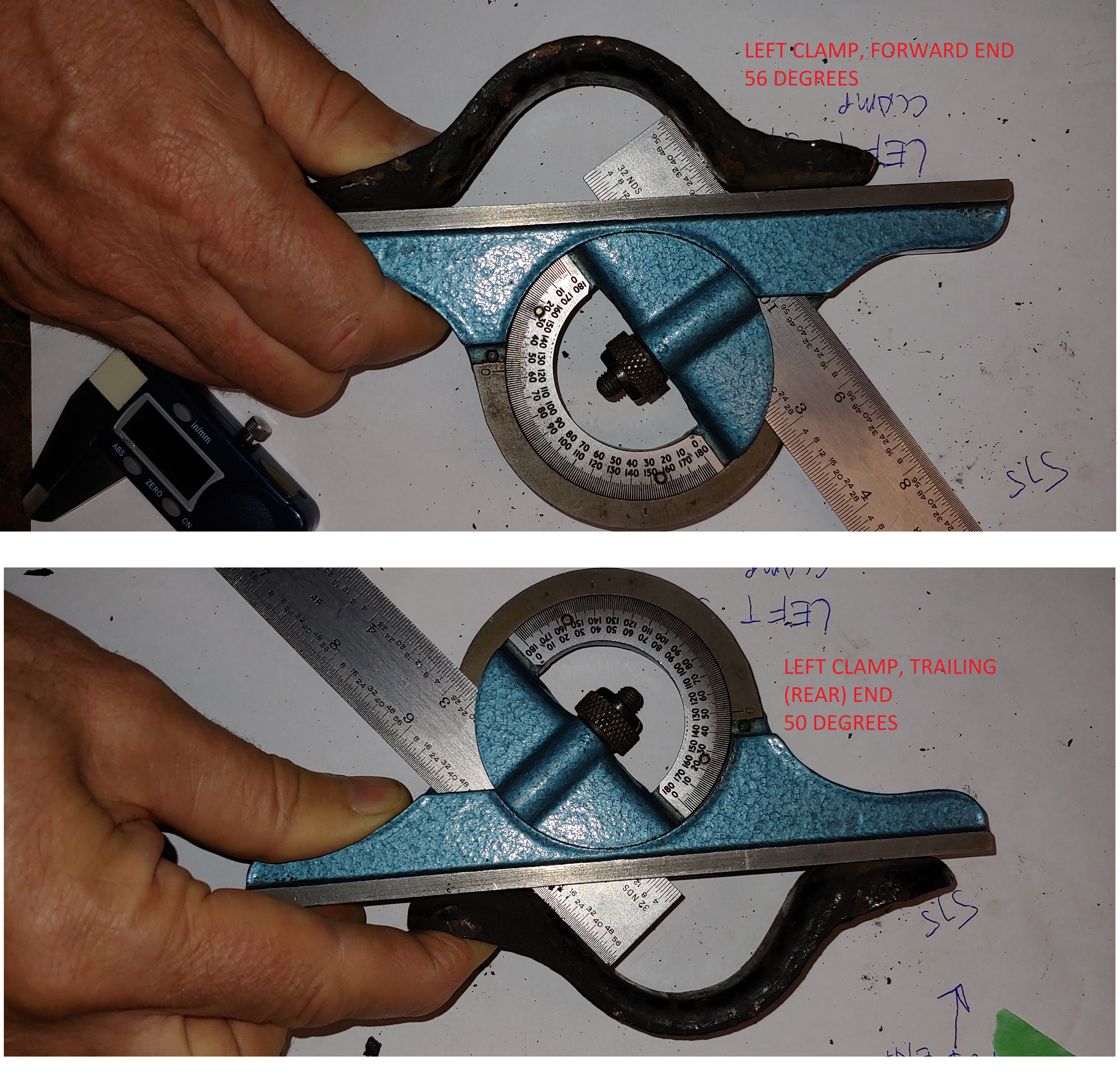
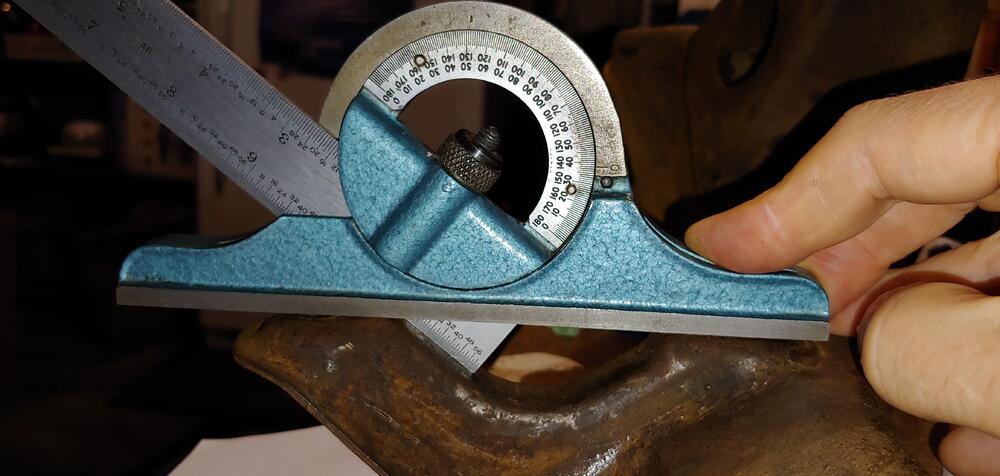
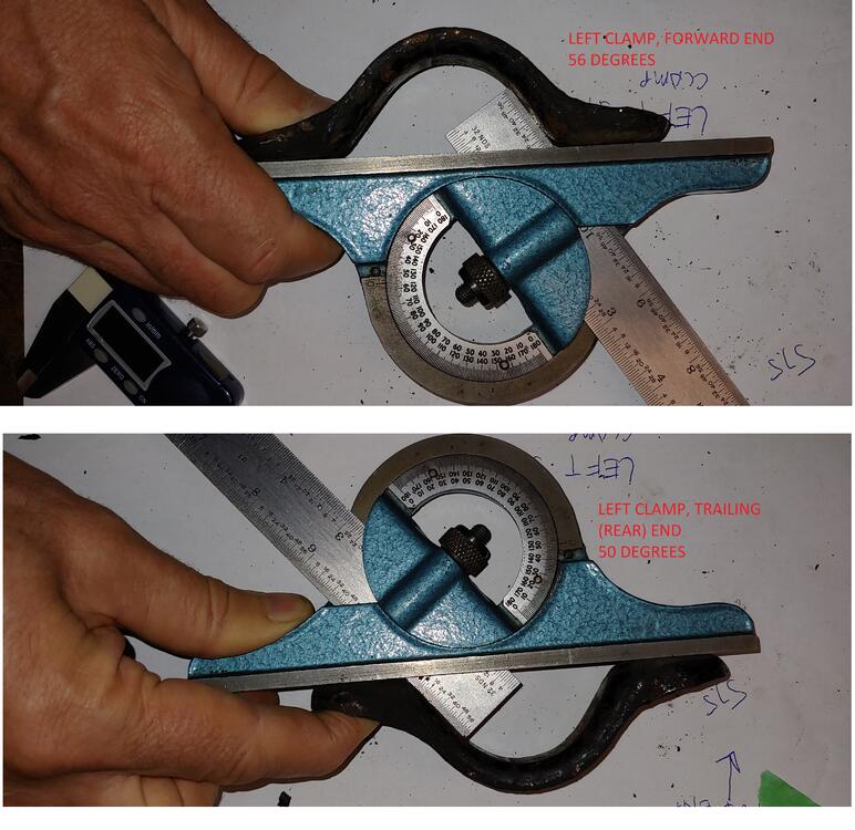
Interesting, Good eye @Captain Obvious. My front suspension is out so I thought I would check the clamps on my 7/70. I took the left clamp of and took measurements of the angle for the forward and rearward ends. The forward end measured 56 degrees and the rear measured 50 degrees, the bottom face was quite parallel for both ends. Thanks for posting this, I probably would have missed it. Good reference for when I go to reassemble at the end of my resto.
-
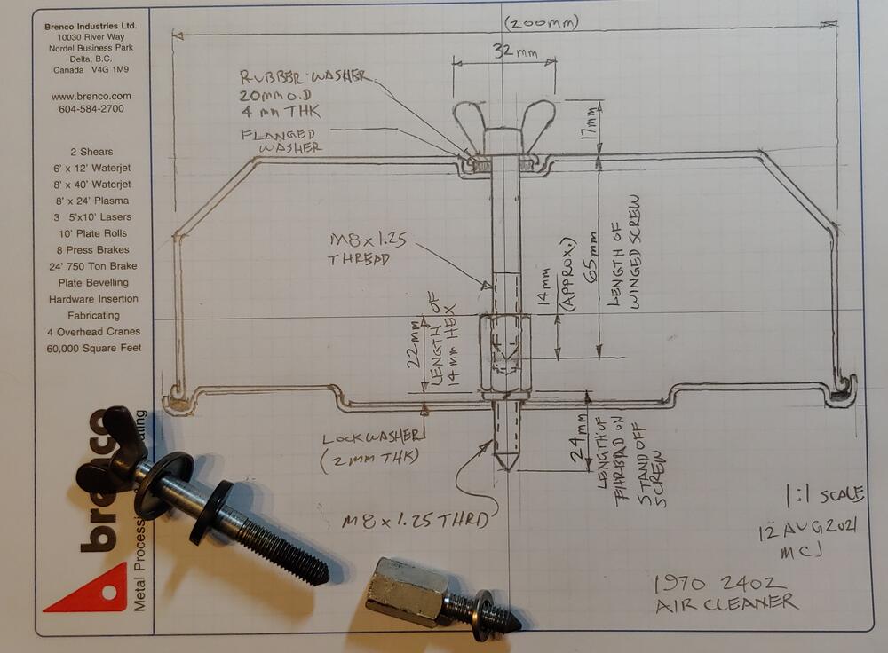
Here is a quick sketch of the air cleaner assembly on my 1970. Hopefully it might help with your search for hardware.
-
If I remember correctly you have to put the filter in to the cover with the winged screws and install them together.
-
I liked that one as well. It was actually created by @zKarsand posted by @Zup here, on this thread that has a lot of good info on the subject of fasteners
-
@grannyknot My 7/70 has one.
-
Your welcome, glad I could help. And thanks in advance for the great references in your build thread. They will help a lot when it comes time for me to re-assemble and as I clean up the parts for my car. Cheers, Mike
-
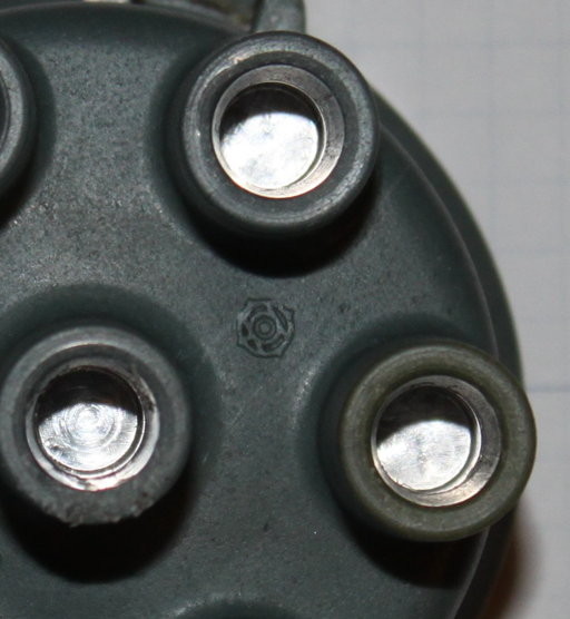
Thanks for checking. If the distributor cap is the original type it will have a Hitachi logo on it like this,
-
-
It would definitely be worth checking, if they are original they would have the manufacturers name, Yazaki, a year of mfg and some symbol graphics. In early 1971 the graphics changed from yellow to white. the style of the connector boots at the distributor cap look look original to me. I am very interested to see your findings. Here is a discussion I started that shows the details and differences:
-
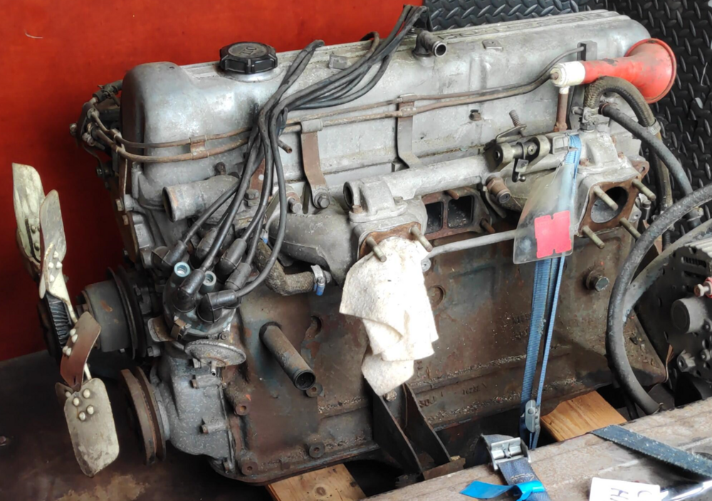
@bartsscooterservice You guys over there got all the cool stuff. Just at a glance I see: - non emissions (EURO) balance tube - single groove balancer pulley - greenish gray distributor cap (original?) - original spark plug leads (are they date coded?) it would be great to pictures of the labeling on them. Overall a great score.
-
Thanks, I also find it interesting to reflect on the design and assembly techniques that were used by Nissan, as the technicians assembling our cars would surely have been under pressure to get things done quickly. This one of the reasons I have been going slowly with the disassembly process. Taking the time to smell the roses, so to speak.
-
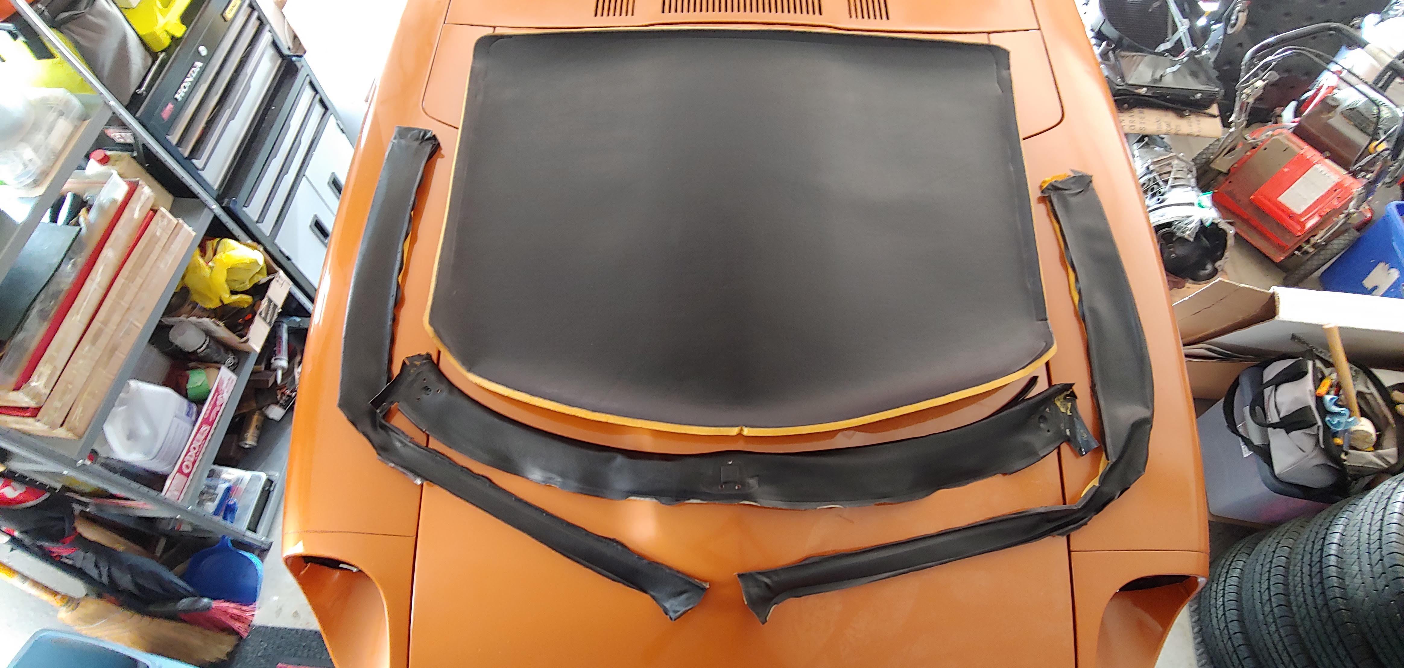
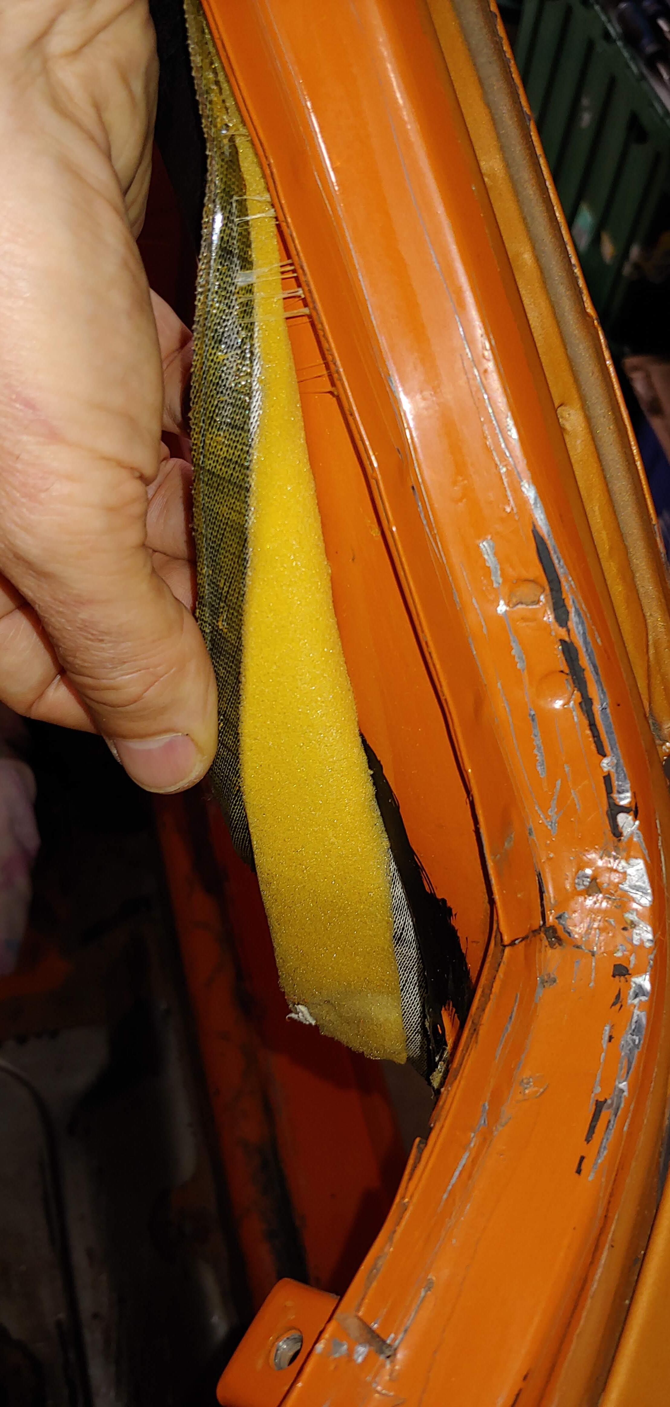
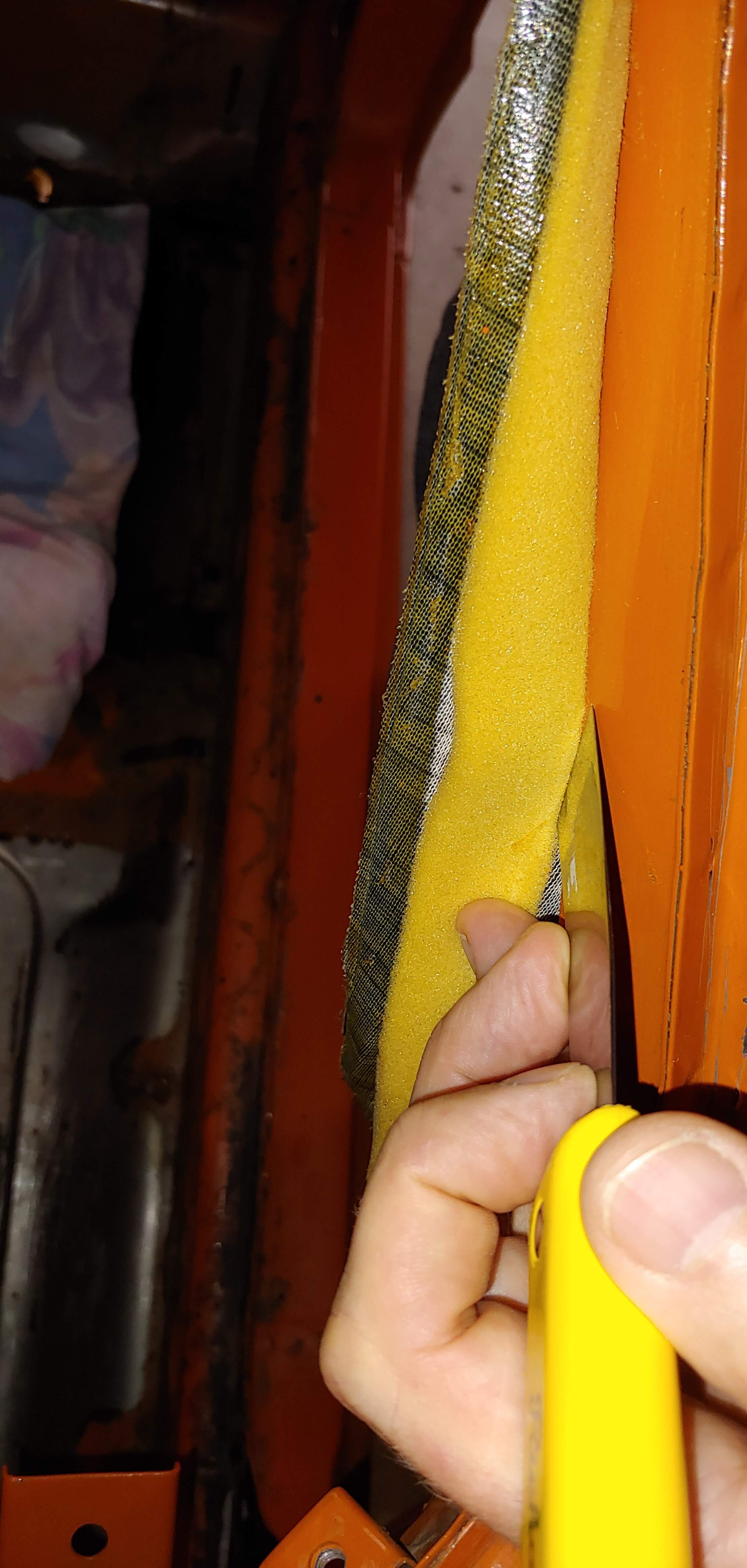
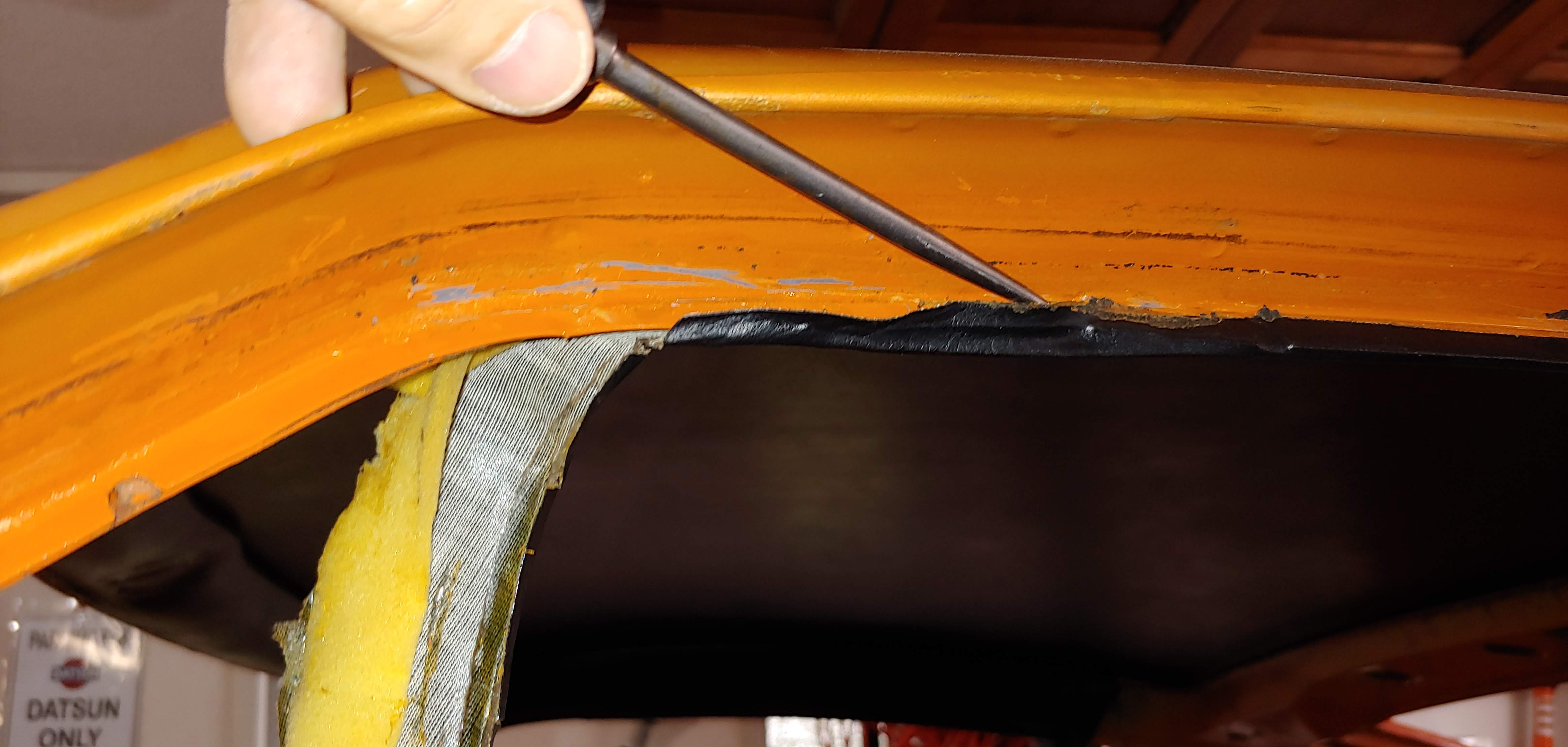
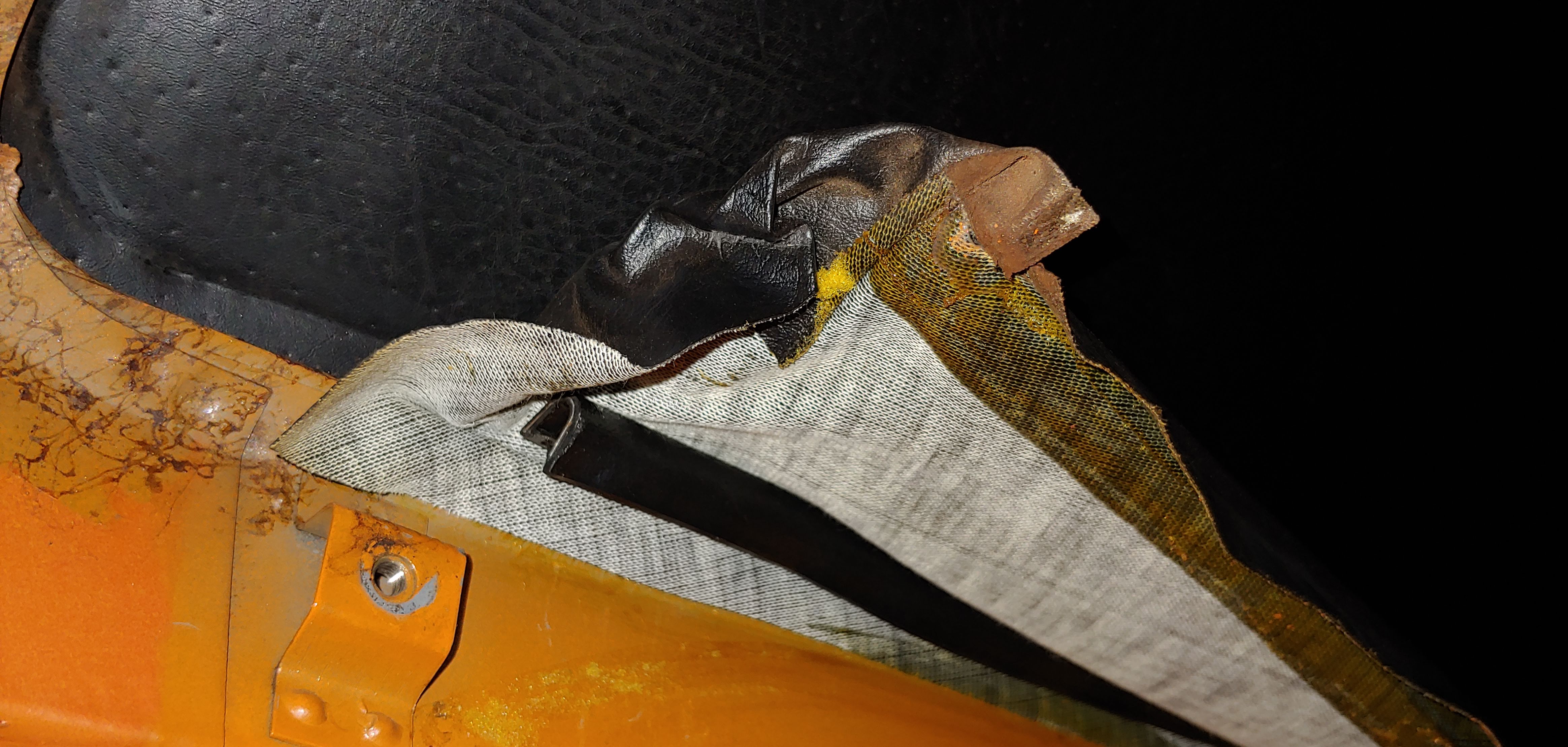
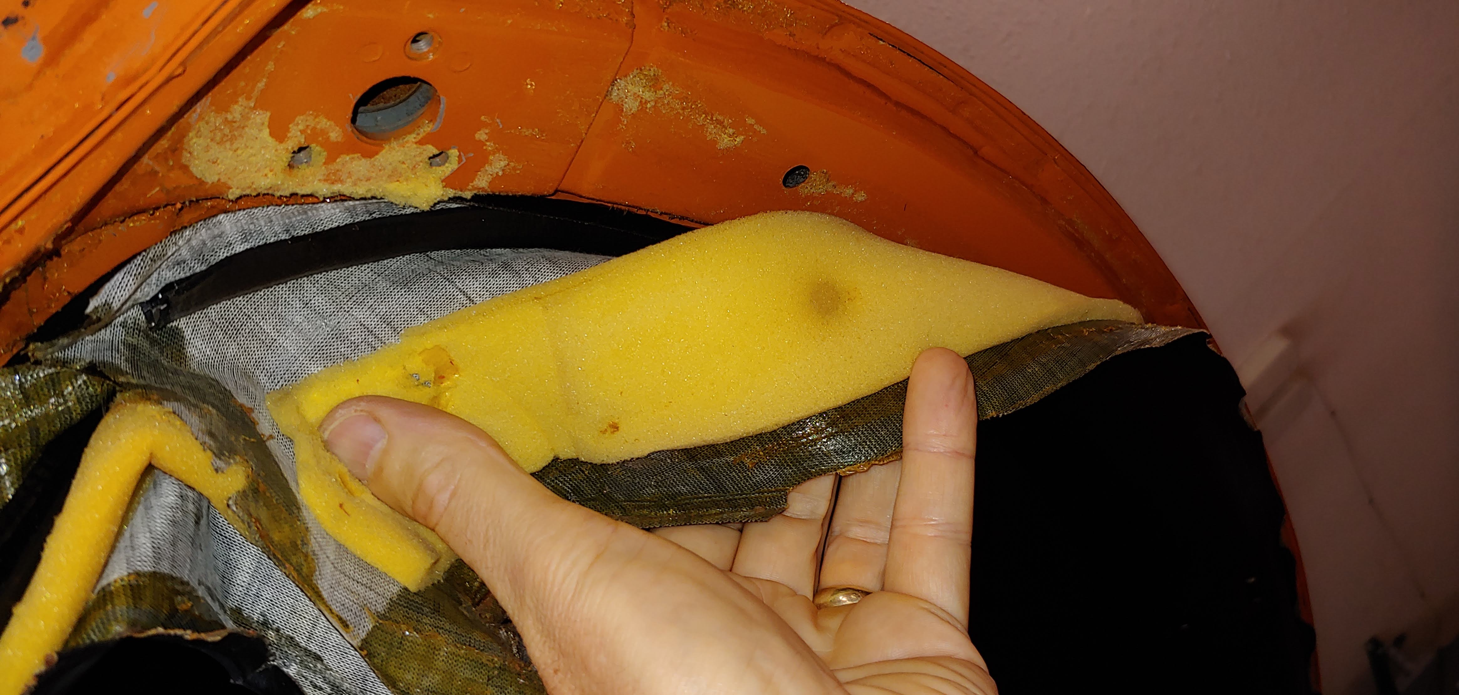
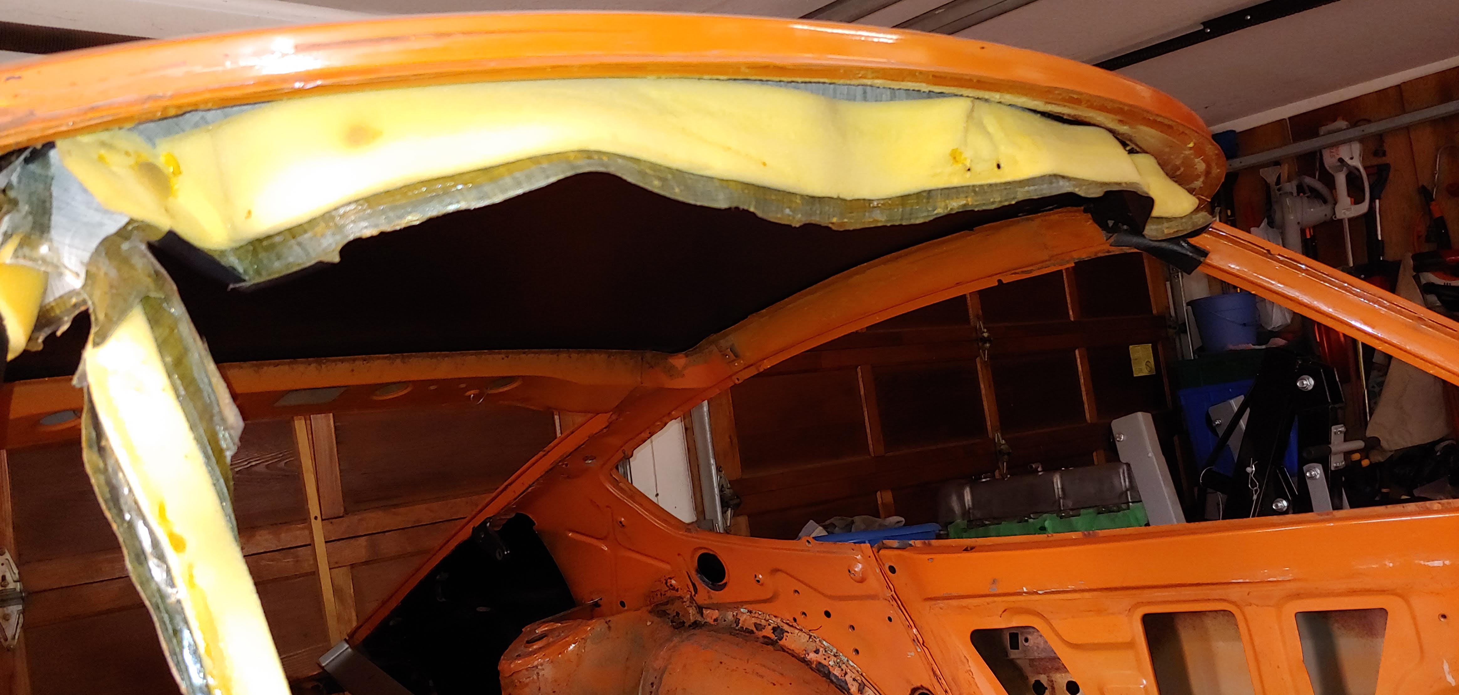
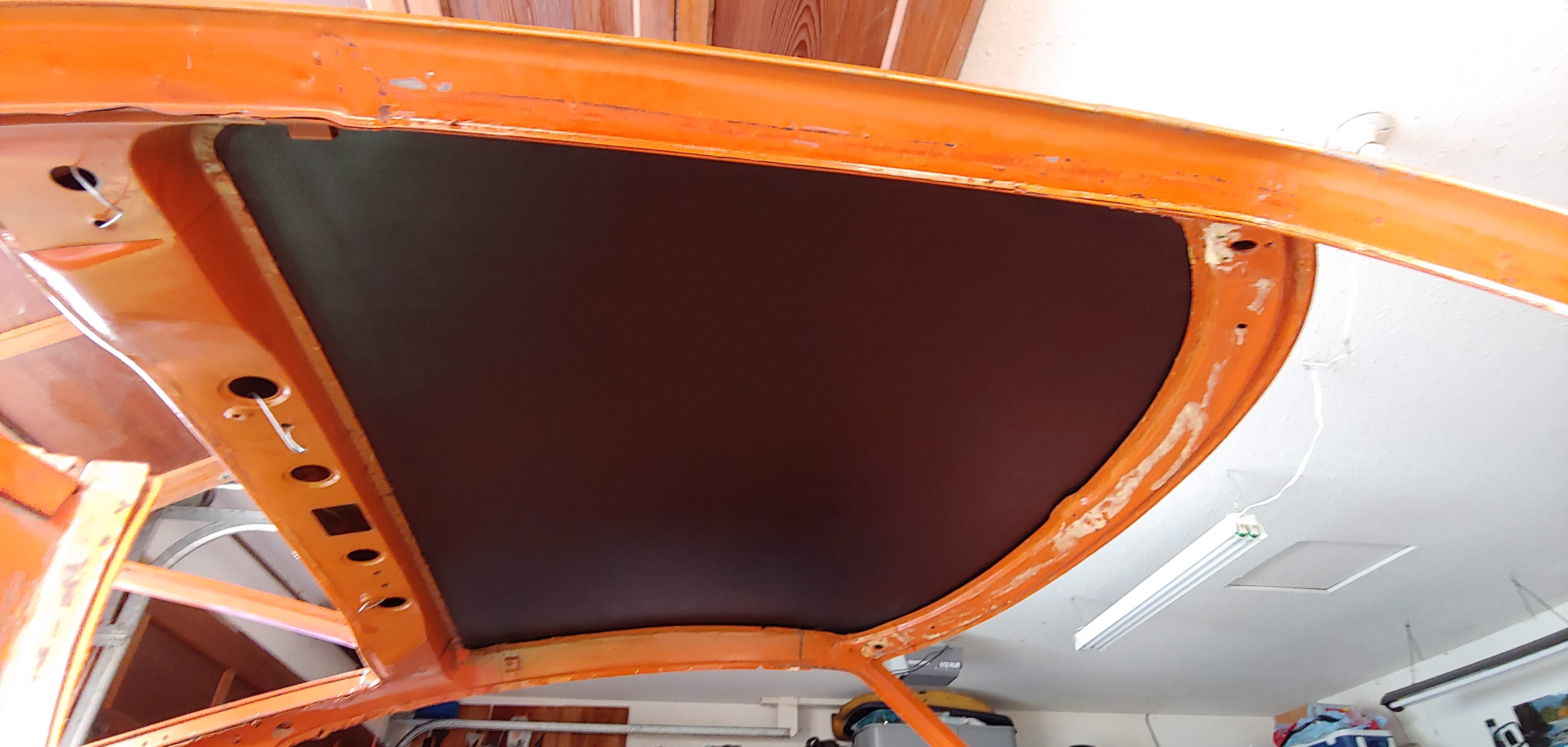
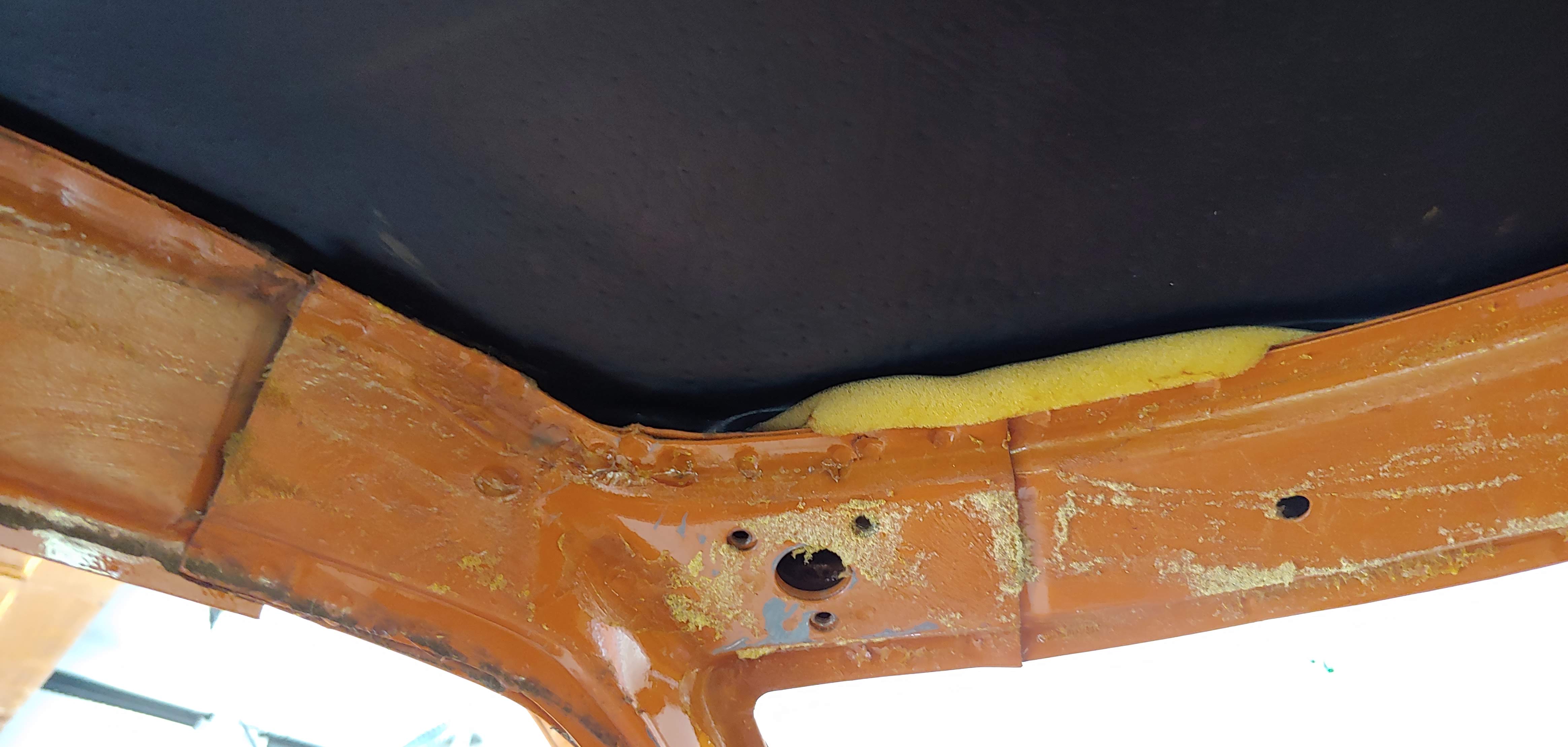
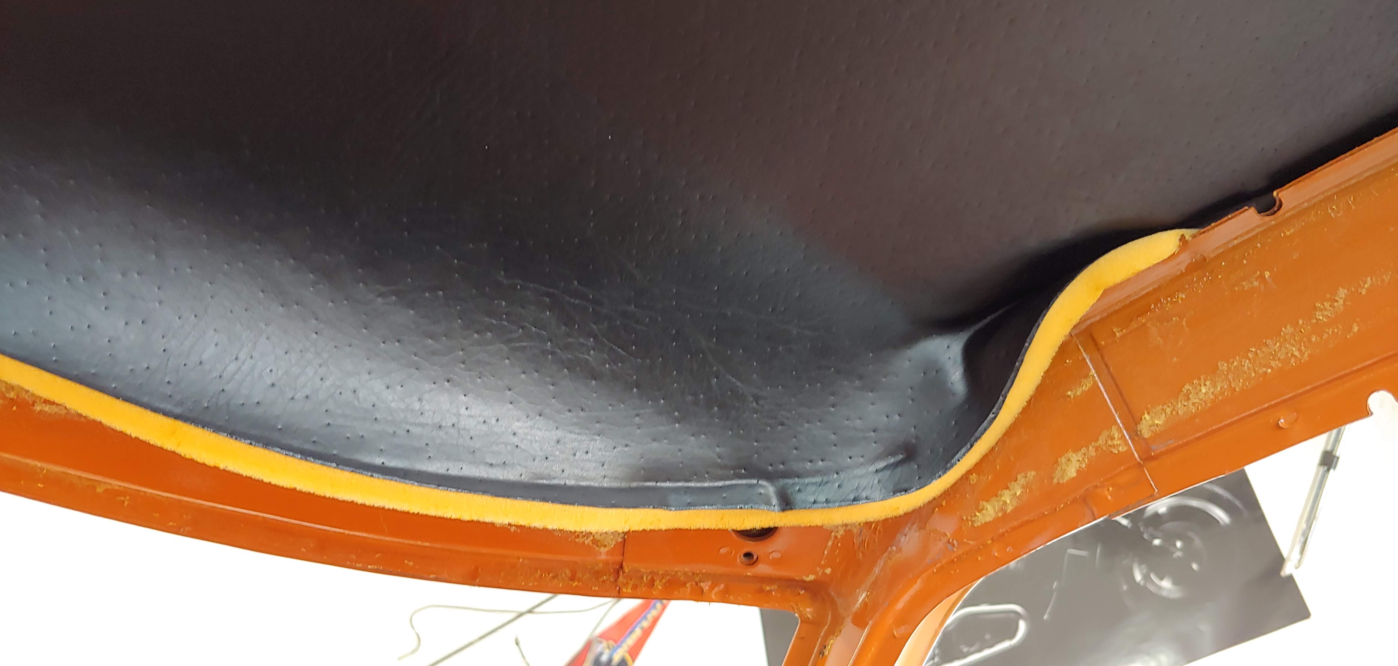
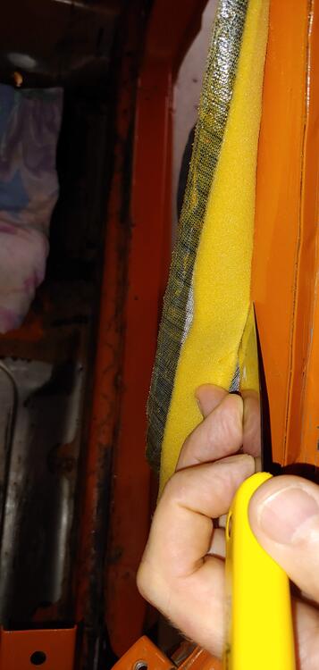
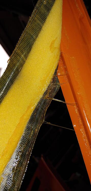
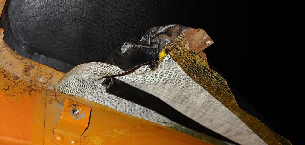
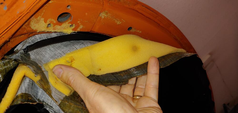
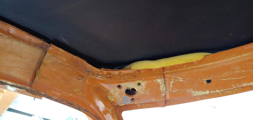
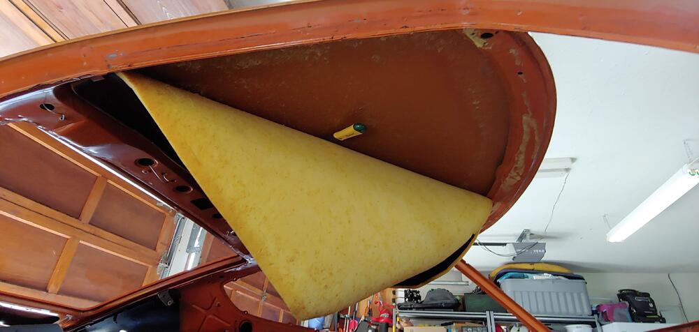
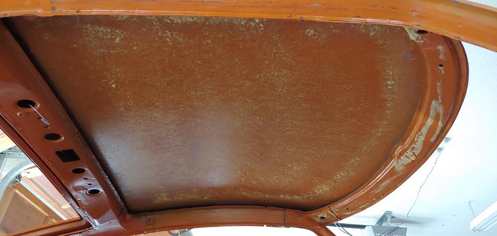
This weekend I removed the headliner and surrounding padded vinyl trim and A-pillar trim. I had a little anxiety about doing this as they are are in very good shape. Luckily all came out with no issues and will be reusable, including the foam padding. I took lots of pictures of the joint details to help when I reinstall. Here are some pictures of my process, the only tools I used were a 1.25" paint scraper with corners rounded off and an awl. I started at the lower end of the A-pillars and carefully peeled back the vinyl exposing the foam padding. In some areas I could do this with just my fingers and other areas I had to use the scrapper to break away the adhesive as I pulled. When I got to the vinyl over the door opening I used the awl to break the adhesive as space was limited. For most of the length the foam was glued at the edges to I had to go very slow using the scraper gently while keeping light tension on the foam. There is also U shaped welting that holds the vinyl to the roof frame that had to be pulled away. After removing the A-pillar and over the door opening trim I used the same process for over the windshield opening. For the headliner I found that there was no adhesive where it tucked into the roof frame but there was a very uniform coating of the adhesive on the rest. To get started I poked my little finger in to the hole for the LH visor mounting bracket pushing the unglued edge of the headliner and at the same time gently pushing inward with the fingers of my other hand until I had exposed the edge of the headliner foam. From there I could work the unglued edge out of the frame for the full perimeter. I freed the headliner using the scraper with a short jabbing motion, keeping light pressure on the roof and holding the headliner with light tension with my other hand. I had the scrapper at about a 30 to 45 degree angle to the roof while doing the scrapping. Using this technique very little of the foam was damaged. All in all it when quite smoothly and there was very little foam reside left on the steel. It was definitely worth taking my time to be able to salvage everything.


-
Thanks for this, I like the idea of getting your own carbs back as well. His prices look very reasonable.
-
Hey, @inline6I missed reading this part of your post so I edited mine above a bit. BTW your carbs look great, are they from ZTherapy?
-
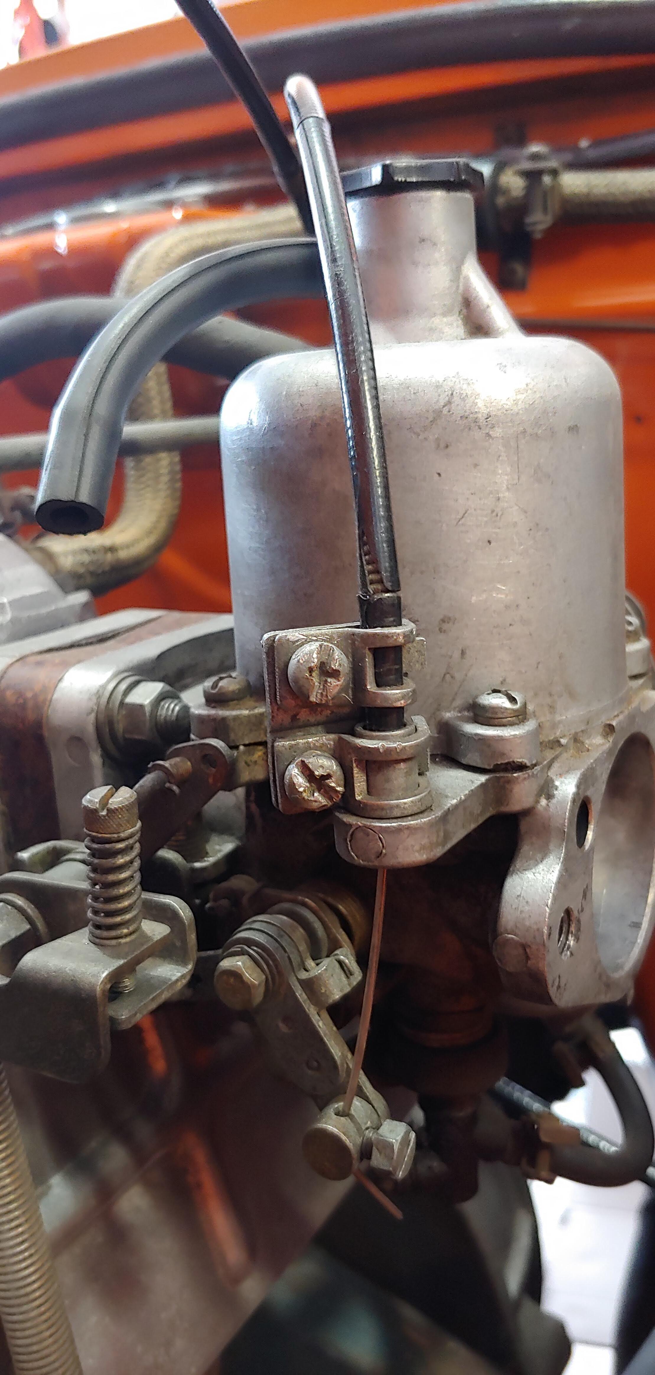
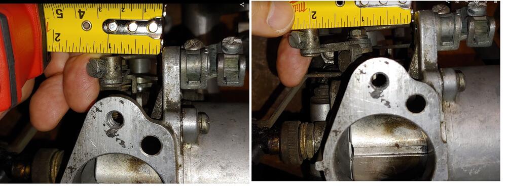
I'm also of the opinion that your car did not originally have bellows, as they appear to have started for the 1972 model year in 9/71. I have never seen what are called complete assemblies (early type) offered for sale with them. Not saying there is anything wrong with adding them. Here are some measurements that might help with adding them, for anyone who is interested. The travel required for full motion of the choke linkage is 1-1/8" and the compressed length of the bellows must be 3/4" or less. This is based on open and closed measurements I just took from my carbs, and I also checked at the choke lever on a drawing from a parametric 3D model I created a few years ago. Hope this info helps anyone trying to add bellows, Cheers Mike

-
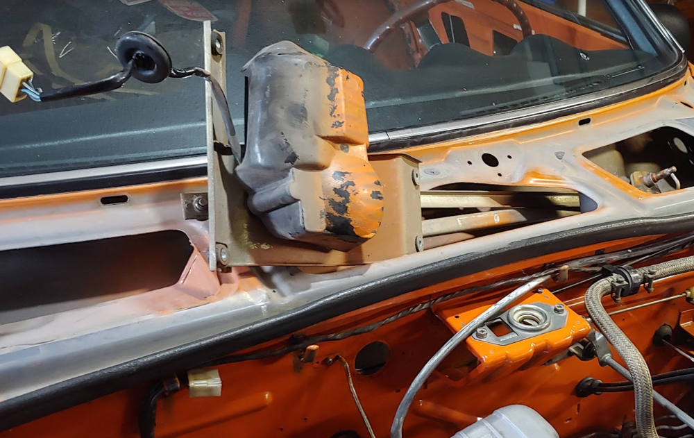
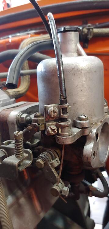
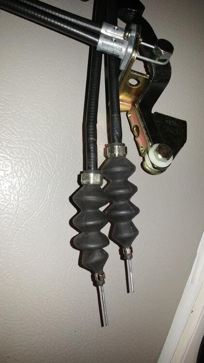
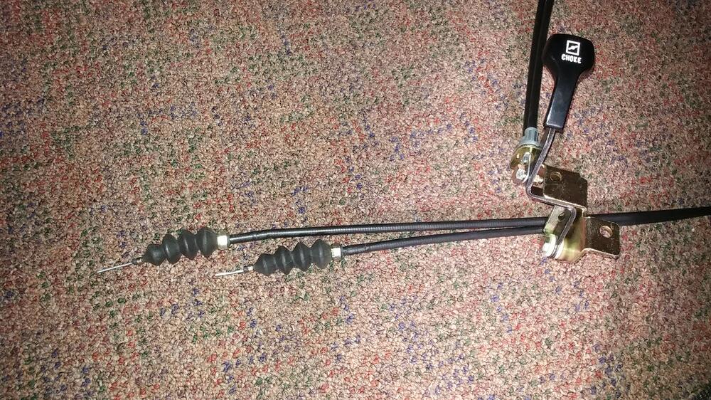
Here is what my early choke cable assembly looks like. There is not enough room for the bellows after accounting for full travel of the choke.
-
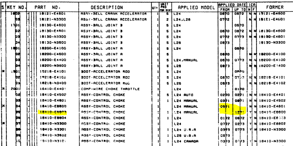
I believe, It was started 09/71, the one I had was a 18410-E8803, but I think 18410-E8800 was actually the first version on the "new design" and it started 09/71.
-
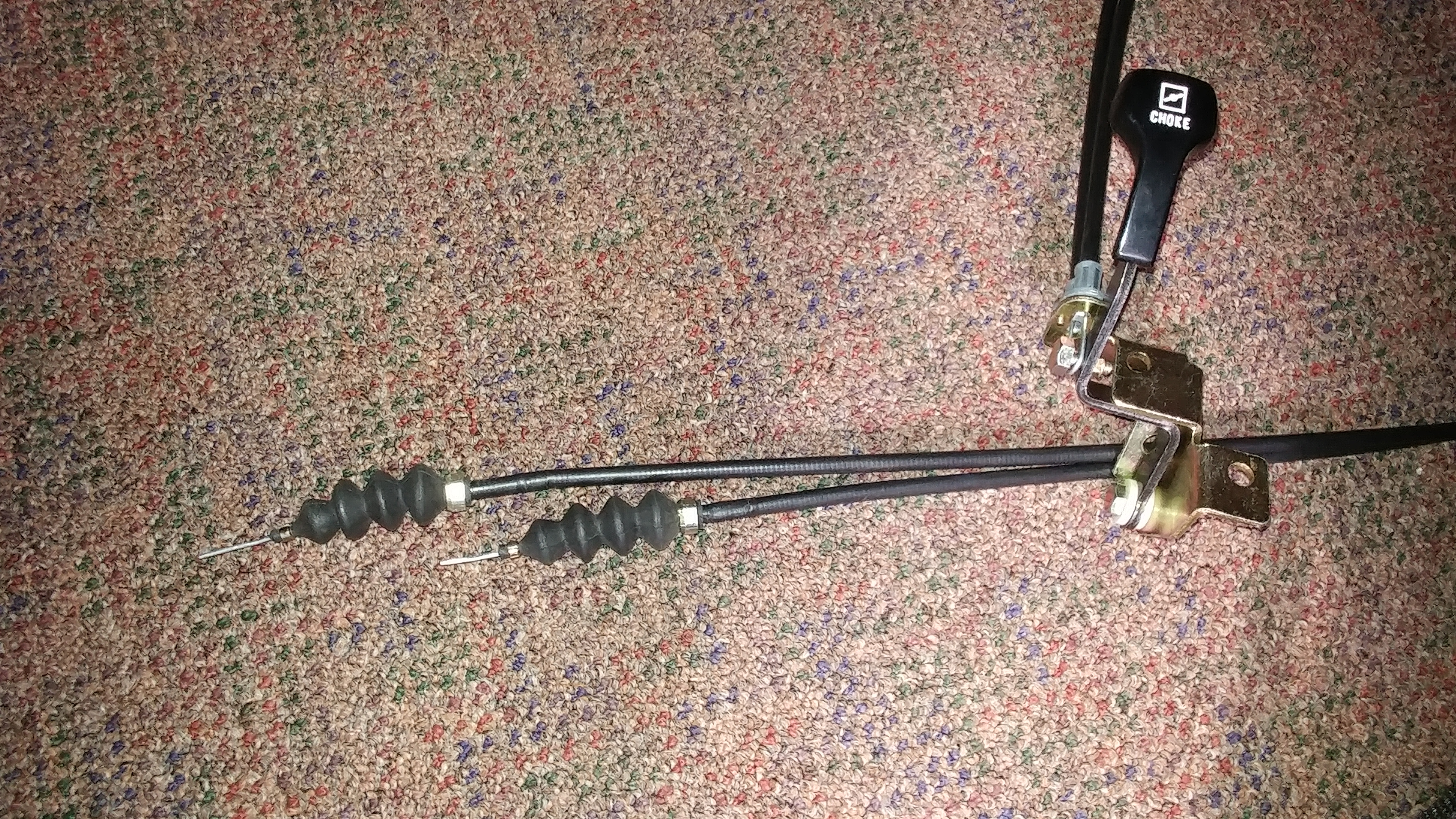
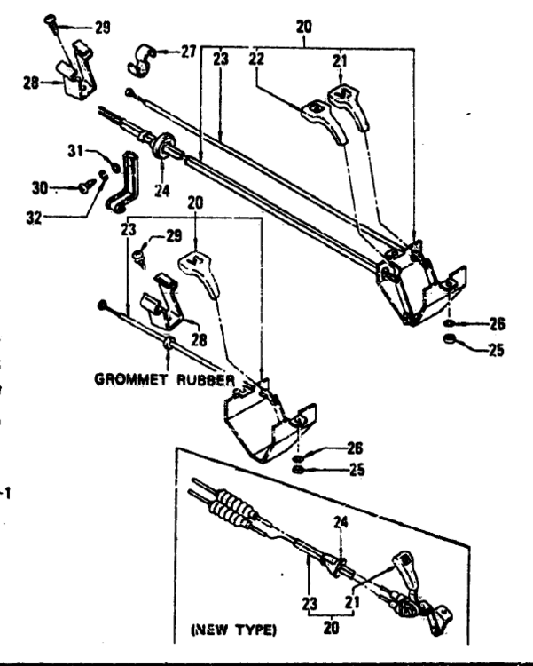
Does your car have the new style choke cable assembly (1972) or the early 70/71 style? Looking at the BaT sale for your car, it looks like the early type. The early type did not have the rubber bellows. I know this because I accidentally bought a 1972 style choke cable assembly and had to remove the bellows to use it in my 1970. Even then it was a problem because the new style cables are shorter. If your car has three screw carbs they might work as I believe the linkage was different than the four screw carbs on mine. I ended up selling it and repairing my broken early cable. Here is a discussion from when I sold it on here, Here are a couple more pics I took before I sold it. For reference, here is an image from the parts book. You can see the bellows on the "new type" and none on the early one.
-
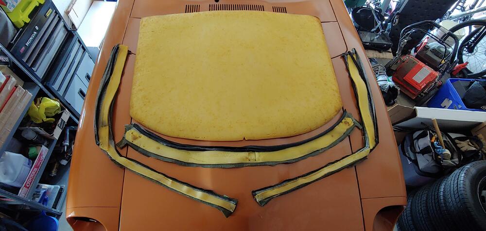
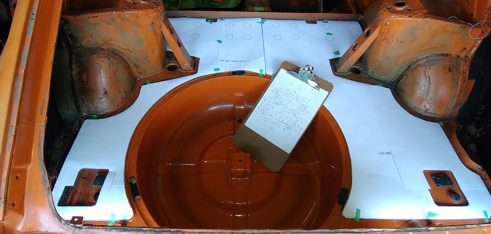
Continued with creating templates for the tar mat insulators. I have finished and uploaded templates for the rear deck area to our downloads in the cad files section, https://www.classiczcars.com/files/file/142-1970-240z-floor-tar-mat-templates/ Here is a picture of testing the templates to confirm fit. All that is left to do is the transmission tunnel area, hopefully I will get that done soon, before the shell goes to the body shop.
-
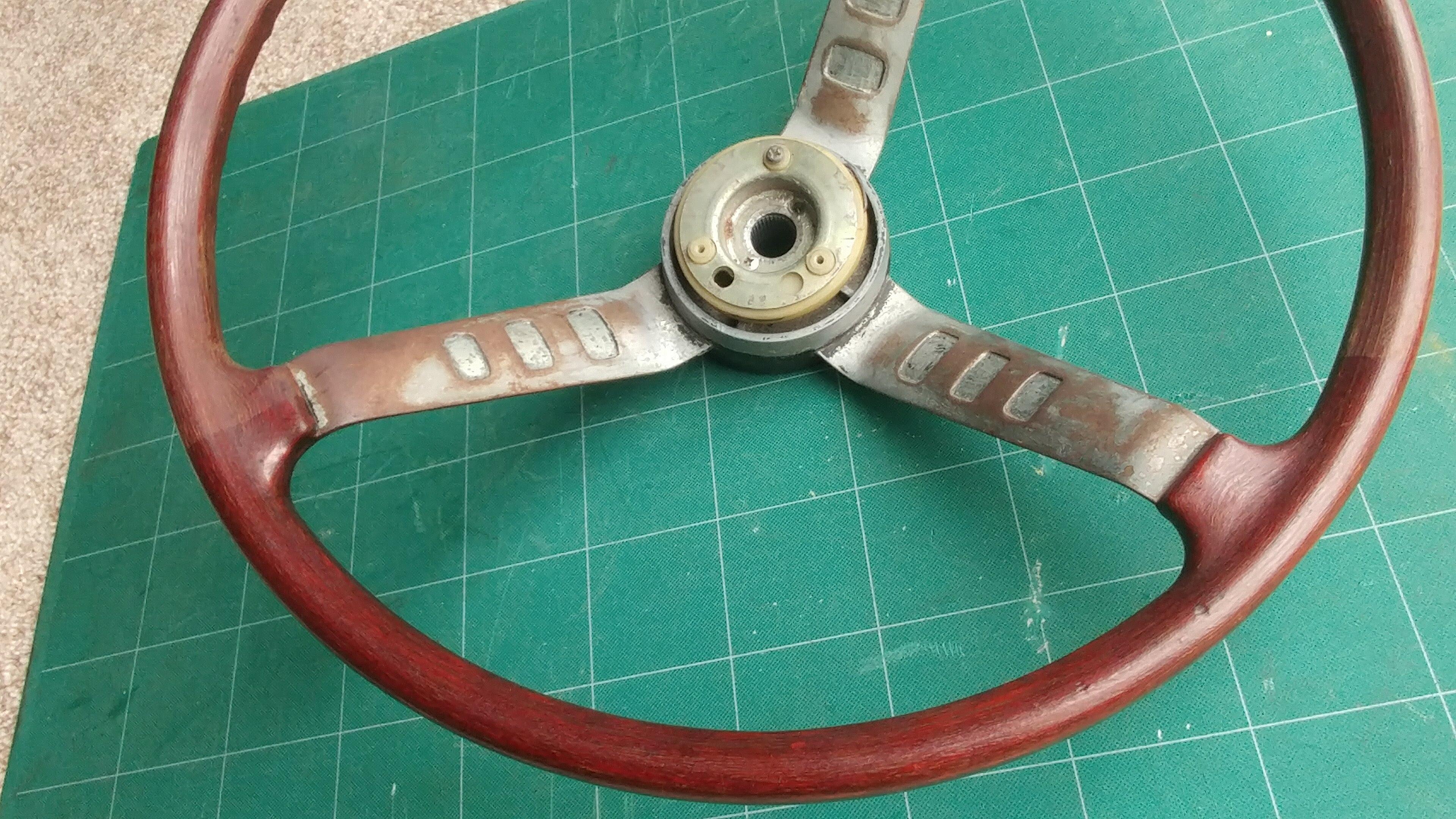
A little of topic but I have tested a product called Revive to refresh the finish of an old steering wheel from my parts car. I was very impressed with the result and there is no greasy feel to the surface. This steering was very grey looking before I started, but I didn't take a picture at that state. I first cleaned the wheel with soap and water and after it was thoroughly dry I applied the product.


-
Amazing attention to detail. Very inspiring.
-
That's the the idea, carefully flex the window piece away to get a gap on the rear vertical edge to slide the rear panel in behind. Like I said before my preferred method is with the window panel out.
-
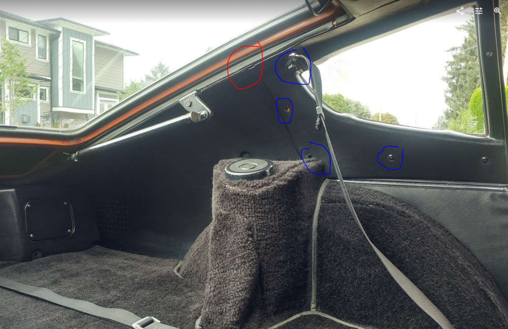
In my case the carpet was glued down, so it was better to remove the quarter window panel. Or at least the fasteners and seat belt shoulder strap as shown in blue here, that method also worked for me as long as I was careful.
-
No question that you have to be careful when flexing these old panels. It can be done if you are careful without removing the quarter window panel, but it does help. On mine it was necessary because of the change from vinyl to carpet on the shock towers. Good luck with what ever method you use. At least the weather is warm, which helps with flexing the panels as compared to winter temps.