


.JPG.cfcada9cf1c1b502df3f5f2f2ca3ff36.JPG)

SteveJ
Free Member
-
Joined
-
Last visited
Everything posted by SteveJ
-

-
Find a weather resistant maxi fuse (or ANL fuse) holder if you are planning to mount the fuse holder where the current fusible link holders reside. I also suggest using ferrules on the wire ends to improve clamping force on the wires. You will need to find a ferrule crimper that can handle the wire sizes (relatively easy to find on Amazon). Here is an example of a marine ANL fuse holder: https://www.crutchfield.com/p_867FUSEDIS/Wet-Sounds-WWX-FUSE.html
-
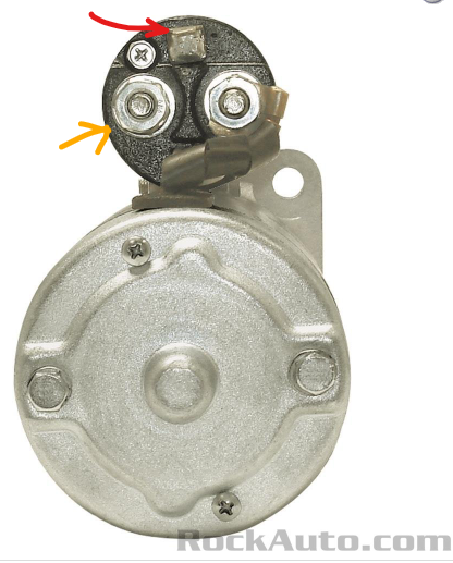
The click you hear is normal. That is the accessory relay. Move on from that. You need to verify voltage to ground (or negative) at the starter solenoid when the key is in START. That is the black/yellow wire. Suggested actions: Pull the black/yellow wire off the starter solenoid. Put the positive voltmeter lead on the black/yellow wire and the negative lead on the battery negative. Have your assistant turn the key to the START position. Measure the voltage (and report it here). If you have around battery voltage at the black/yellow wire, then here is the next test. Keep the black/yellow wire removed. Ensure the car is in neutral. Get a screwdriver. Touch the screwdriver to the positive cable on the starter and the spade terminal where the black/yellow wire was. You don't have to hold it there for long. If it doesn't engage the solenoid immediately, try a couple of more times. Red arrow - Spade for black/yellow wire Orange arrow - Positive cable from the battery. If the solenoid immediately engages, then your starter solenoid is probably in good shape. Report your results.
-
Also: https://www.vredestein.com/classic-tires/products/990-SPRINT-CLASSIC/ Tire Rack link for the above tires: https://www.tirerack.com/tires/tires.jsp?tireMake=Vredestein&tireModel=Sprint+Classic&sidewall=Blackwall&partnum=7HR4SC&tab=Sizes
-
Look here: https://cokertire.com/amfinder/index/index?finder_id=33511382
-
https://www.zzxdatsun.com/
-
@Mike, I think osinpowe may be some kind of bot or spammer.
-
 Well @Gav240z was here back in January. If you send him a PM, he might get an email notification.
 -
I just semi-permanently installed the electric fuel pressure gauge in my car. My job (and helping the parts cannon crowd) has conditioned me to have more diagnostic info readily available.
-
The redneck way is to use a long piece of hose. I took a different direction. I went a 0-30 from this brand: https://www.glowshiftdirect.com/elite-10-color-100-psi-fuel-pressure-gauge/ If you want a cheaper alternative: (Wrong part removed) https://www.ebay.com/itm/176895594944?_trkparms=amclksrc%3DITM%26aid%3D1110006%26algo%3DHOMESPLICE.SIM%26ao%3D1%26asc%3D20200818143230%26meid%3D5a579eb1d3964f638fde15fc3eb8a2e0%26pid%3D101224%26rk%3D4%26rkt%3D5%26sd%3D176367258697%26itm%3D176895594944%26pmt%3D1%26noa%3D1%26pg%3D2332490%26algv%3DDefaultOrganicWebV9BertRefreshRankerWithCassiniEmbRecall&_trksid=p2332490.c101224.m-1 I can't vouch for the quality, though.
-
The fuel pressure gauge should go between the fuel filter and the fuel rail.
-
-
The two ways a diode can fail: Open or Closed. Open: Detection - You will see infinite resistance (OL) no matter what orientation you use with your meter leads. (Always try both directions.) Result - The alternator won't charge. Closed: Detection - You will see zero (0) resistance no matter what orientation you use with your meter leads. (Always try both directions.) Result - The alternator will charge, and the car will probably try to keep running with the key off since this will backfeed the ignition circuit.
-
-
-
-
-
-
-
There are times to be pedantic. This isn't one.
-
Black/yellow - 12VDC switched from key in START. Black/white - 12VDC switched from ignition relay. The ignition relay coil is energized by the key in ON.
-
Another great share, Alan. I caught a glimpse of the link to the article on Facebook, but I didn't have the time to click on it then. I know there are plenty of us who appreciate the chance to understand what was different in other markets and why. Thank you @JDMjunkies.ch for making the time to write the article.
-
That reminds me of a joke. What do you call someone who speaks two languages? Bilingual What do you call someone who speaks several languages? Polygot What do you call someone who speaks one language? American
-
You can reach out to them on Facebook: https://www.facebook.com/s30.world
-
@HS30-H Alan, I wasn't looking for diplomacy. I prefer accurate. I've been reading your posts long enough that as I read through the link, I thought there was something fishy about it. The first thing was that the pricing didn't seem to fit what I recalled hearing about the 432 or 432-R market.

