.JPG.cfcada9cf1c1b502df3f5f2f2ca3ff36.JPG)

SteveJ
Community Member
-
Joined
-
Last visited
Everything posted by SteveJ
-
-
I'm glad you found the links useful. Phil, aka Blue, inspired me with all of the tech tips he created on his club's website.
-
With the help of a couple of great people, I changed the front struts, springs and ball joints. I used the Chevette springs, cutting 2.5 coils. It looks like I need to cut 3 in the front. Next week will be the rear springs & struts.
-
Do you have a ballast resistor? Is it a 4 wire or 3 wire tach?
-
-
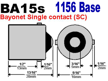
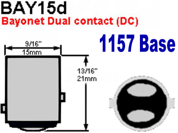
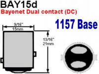
One issue that I believe is happening is that you have an 1156 bulb where you need an 1157 bulb. That is why everything lights up when the parking lights are on. As you may notice the 1156 has one contact at the bottom, whereas the 1157 has two. Did your side markers light up with the hazard switch? That would be another indicator of the wrong type light bulb in a socket. Another issue you may have is a problem with your hazard switch. The circuits for the turn signals and your brakes go through the hazard switch. When the hazard switch is on, the circuits for the brake lights and turn signals are interrupted. When the hazard switch is off, the circuits are supposed to be restored. However in an older switch, the contacts may be too dirty or may have moved slightly. Here are a couple of references on the subject: Early Hazard Switch | Fiddling With Z Cars Hazard Switch ? Brake Light ? Turn Signal Circuit Analysis | Fiddling With Z Cars I suggest you remove your hazard switch and make sure there is continuity between the two green wires (with no stripe). If not, there is your issue.
-
Did you replace the alternator at the same time?
-
Put in a thermostat. The cooling system is designed to have that restriction in there.
-
Why do you want underdrive pulleys?
-
PM sent.
-
I know a guy in Lawrenceville who could weld it for you. He's a Z guy, too.
-
And I found this, too...Cable Ties & Accessories | Parts | Panduit
-
I got close...McMaster-Carr Look at the panel mounted ties.
-
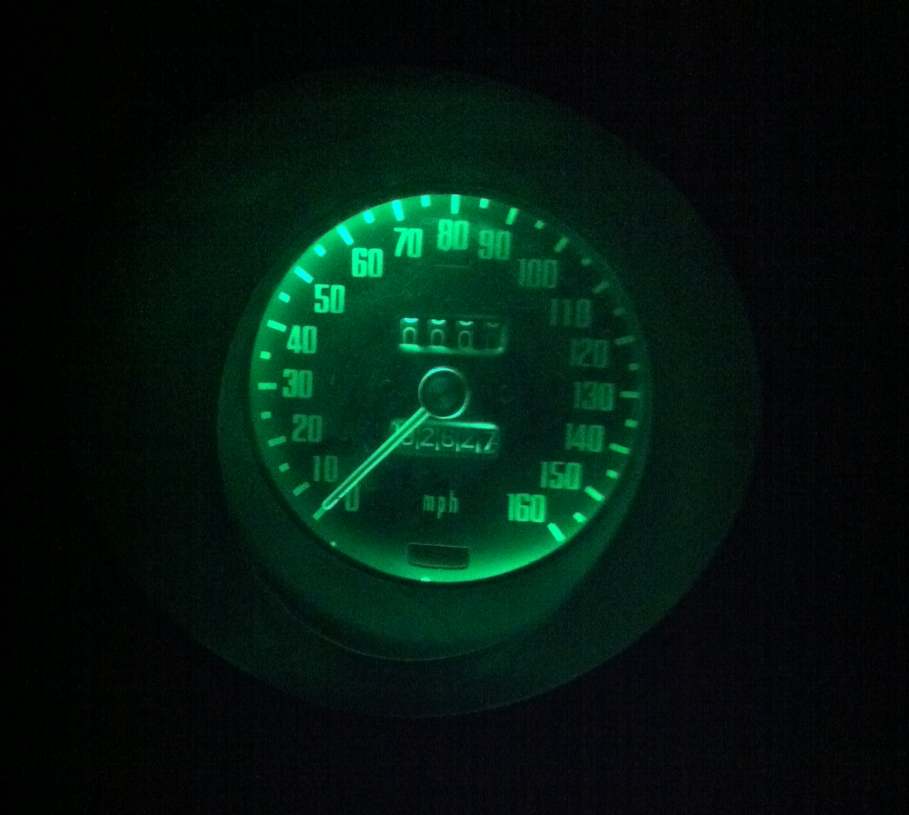
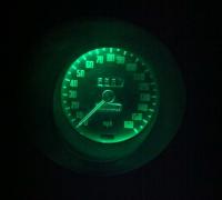
Here's a picture of a speedometer I used to test the new LEDs and bulb sockets I described in my earlier post. I know I'll be able to see that better at night.
-
They certainly look handy to hold the metal in place for welding.
-
You could always use the Internet Wayback Machine to see if the site is archived. I've brought some old links back to life that way.
-
I've been doing some experimenting lately. I bought some wedge bases for the instrument lights (10 Pcs Heavy Duty T10 168 194 2825 Wiring Harness Sockets Pre Wired | eBay) and some low-profile wedge bulbs (green - Amazon.com: Jtech 10x T10 8-SMD Green LED Car Lights Bulb W5W, 147, 152, 158, 159, 161, 168, 184, 192, 193, 194 2825: Automotive red - Amazon.com: Jtech 5x T10 8-SMD Red LED Car Lights Bulb W5W, 147, 152, 158, 159, 161, 168, 184, 192, 193, 194 2825: Automotive blue - Amazon.com: 8x T10 194 168 501 4-smd 3528 LED Car Light Bulb Blue: Automotive). The green bulbs have 8 SMD LEDs, and they all point forward, illuminating my test gauge fairly well. The low profile bulbs make it where I don't have to remove the lenses from gauges, too. I am looking forward to doing the conversion.
-
The Georgia Z Club surrendered to the masses and is using Facebook. The old website re-directs to the Facebook page. I believe we actually attract more traffic that way. Oh, and if you're worried about FB privacy, can't you just use fake info?
-
-
Heck, I'll help. I can probably recruit some other guys to assist, as well. Stripping party! Wait, that sounds weird.
-
I'm also interested in the license plate light.
-
By the way, while the address says Gainesville, I live in NE Forsyth County.
-
Okay, not too far away. I would just have to have a plan to stash the 240, or see if he would part with the hood.
-
Okay, where in Cumming?
-
If necessary... Datsun 510 120Y B210 240Z Side Marker Lamp Red Amber | eBay