


.JPG.cfcada9cf1c1b502df3f5f2f2ca3ff36.JPG)

SteveJ
Community Member
-
Joined
-
Last visited
Everything posted by SteveJ
-
I found out this morning that there will be at least one more Z car. David Martin also had his car accepted. Now I wish I made plans when Randy first told me he was trying to get his car in.
-
The ones I purchased had the round head screws. Unfortunately, I can't remember from whom I purchased them.
-
I do want to perform a compression check on the motor. I've been busy helping a friend with his LS1 240Z. If I can remember, I'll put the car on my ramps to see if I can get the block type. I also need to check the fuel pressure and decide if I am going to change out the fuel pump. Finally, there is some re-wiring I want to do in order to power the fuel pump while starting. Have you planned out what fuel pump you're going to use?
-
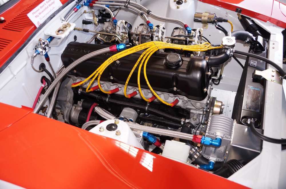
I wouldn't purposely mess with another Steve. We took it easy on the timing since I still had some regular mixed in with the premium. I have just been putting in ethanol free premium since a week before my friends and I did the swap. I wasn't too worried about the details of the engine since I got an insanely good deal on it. It even had a new clutch and flywheel thrown in. Here's a photo of the engine when it was in the previous owner's car.
-
I forgot which block. It's probably an N42, though I know better than to swear on it.It has flat top pistons. I asked the previous owner about details. He said that aside from the head and pistons, it was just a run-of-the-mill build. All I know is that the engine pulls a hell of a lot better than the old tired engine I had in the car.
-
I lucked into an MN47/L28 combo that was a fresh rebuild. It's a nice combination. I had to open up the SUs all of the way to prevent it from being too lean. I've also considered researching a different needle profile to fatten up the carburetors some more. I'm also running square port headers on the round exhausts. I haven't seen any issues thus far.
-
-
There will be at least a couple of Datsuns running around Laguna Seca this year for the Monterey Historics. Glenn Chiou and Randy Jaffe both had cars accepted. John Morton will be driving Randy's car. Okay Bay Area guys, there are no excuses. We expect photos and videos.
-
Seriously, it's difficult to gauge the condition of most of the components just by photographs. I would look at this thread and do as much of it as you can: After that, you'll need to assess the mechanical components. Look at the date stamps on the tires. There's a good chance they are old and rotten. Examine the body above and below thoroughly. What is your target? What kind of car do you want to end up with? That will drive your budget.
-
I would prime the fuel line. The fuel filter is probably the easiest access point.
-
A plan.
-
I have a beat up air cleaner cover I can let you have cheap. I just have to remember where my stash of wing nuts are to secure it.
-
This counts as threadjacking, Charles. To atone for this, you must bring us a shrubbery.
-
The voltage on the injectors will only fluctuate about 2 volts when they are firing. You might consider getting a fuel pressure gauge to install on the fuel line in the engine bay. Get one that goes to 60 PSI. From your follow-up, it sounds like you didn't have pressurized fuel in the rail. I'm not an expert on fuel injection, but I'm thinking the injectors might not be making much of a clicking sound if there isn't fuel in them. In the meantime, download the FSM for your car. You can get it from this site or from the link in my signature.
-
You're welcome. If you have any other questions, post away.
-
It would be unusual for there to be an issue with the turn signal after Dave reconditioned it, but it is not impossible. The turn signal is the point where the brake light circuit and turn signal circuit meet that could cause the issue that you describe. Fortunately a meter and knowledge of the circuits can give us a more definitive answer.
-
-
Yes, they are. They tend to transmit less vibration than the brass ones. Personally I never have been bothered by that with the brass bushings.
-
Adding some dielectric grease in the socket wouldn't hurt.
-
While we are going over things, you do have a condenser attached to the negative wire of the coil, don't you? Make sure the spark plug and coil wires are seated well.
-
Well, if it's in wood shape, you could do a nice mahogany stain on it. That would really stand out. Damn autocorrect.
-
It's probably the turn signal switch. https://fiddlingwithzcars.wordpress.com/2013/01/20/hazard-switch-brake-light-turn-signal-circuit-analysis/ https://fiddlingwithzcars.wordpress.com/2012/12/04/turn-signal-repair/ I'm two hours away if you want a definitive diagnosis.
-
I said we weren't going to get into that.
-
I didn't emphasize it because I was planning to inspect in person, especially since the car has been recently painted.
-
I saw them in person. The current owner is a good friend.


