Namerow
Community Member
-
Joined
-
Last visited
Everything posted by Namerow
-
IIRC, the Reverse Switch is an 'interruptor' type and doesn't care about the quality of its local 'ground'. The switch is normally 'open'. When you engage Reverse, the switch contacts close so that power can flow through the switch and back to the main harness. The switch has a rubber dustboot to protect the 'in' and 'out' terminals from water and crud. On the units I've looked at, the boot had perished and the terminals were pretty dirty. I'd look at that first. The dustboot may be destined for the trash bin. Clean up the contacts and the wire-end terminals, re-install, and then figure out some way to seals things off. Alternatively, just buy a new switch (which may come with a brand-new rubber dustboot). I don't think you're going to find much difference from one switch manufacturer to another, but I would suggest you pick a known brand just to be safe.
-
Eastwood Internal Frame Coating http://www.eastwood.com/internal-frame-coating-w-spray-nozzle.html Tough phenolic resin penetrates, converts and encapsulates the rust on the internal surface Zinc phosphate seals it to prevent future corrosion 24"-long tube with conical nozzle reaches in to spray coating in a radial pattern for complete coverage Aerosol covers 10 sq. ft., qt. covers 50 sq. ft. Fully cures in 24 hours US $18.00 per can. For your small-ish job, one can should be enough. The features of this product that make it attractive are: 1. Zinc phosphate content helps to neutralize whatever rust might already be there, while the resin base seals off the surfaces from exposure to air and water 2. The applicator is a long, skinny tube with a special, multi-directional spray tip on the end -- perfect for what you want to do. I found that the tube had an undesirable curvature that made the tip scrape against one wall of the structure, so I heated it with my heat gun and then flat-rolled on my workbench using a spare piece of flat 1é2`plywood. The tube straightened out very nicely and held its new shape. 3. Cures to a dry surface (unlike wax-type cavity sealers), so won't trap dirt Practice the application first, so that you can execute an nice steady 'pull' for even, run-free coverage. Be careful not to snag the tip of the spray wand on a lip inside the A-pillar, since you will then be holding a 'live' spray can, pointed at your pretty yellow paint. In face, some judicious masking around the top of the A-pillar might be a good idea for just this reason. I wish my Z looked as nice as yours. Keep us posted on your build.
-
I like your theory, Zed Head. The outermost studs, at 8mm, are probably just a bit too small to withstand the bending cycles. The factory's field fix (re-tap for a 9mm stud) suggests that they were thinking along these lines too (note that the 9mm replacement stud would have reduced the longitudinal clearance for the stud within the manifold mounting hole -- which suggests that it's not an issue of actual stud/manifold contact). This kind of fatigue failure is based on number of cycles (assuming that the bending load falls slightly short of causing instant fracture), so a lot of L24's may have the original front and rear studs still intact but well on their way. It may be that the rear stud is found sheared off more frequently than the front one because the rear stud also mounts not only the engine slinger plate but also the coolant rear transfer pipe. It's the latter item that probably got messed with the most (during attempts to replace perished coolant hoses), leading to the 'uh-oh' moment when just a bit of wrench force on the nut snaps off the already-weakened stud. Interesting that Nissan never up-sized these studs from 8mm to 9mm over the full 240-260-280 production series. Maybe the engines had to get up over the typical ownership period (say, 60 to 70 thousand miles) before the studs saw enough thermal-load cycles to start breaking off.
-
Thanks, guys. Some very useful thoughts (and reminders) have surfaced here. I agree (sigh) that the manifolds are going to need to come off. Bore scope or not, trying to accurately mark and center-punch the top of a sheared-off, rusty 8mm stud that's sitting at the bottom of a .5" x .5" hole sounds like a high-odds proposition. And I'm still not sure how one would align the drill so as to end up with a pilot hole that runs true down the centre of that itty-bitty stud. The left-hand drill bit technique sounds tempting, but not tempting enough. The root issue here is galvanic corrosion between the threaded surfaces of a steel stud and an aluminum head. I'm not convinced that drill-generated heat and bite is going to be enough to overcome that -- although I'm intrigued by the notion that the resulting hole might relieve the 'pressure' between the stud threads and the head. I think I'll experiment with another alloy casting I've got lying around that also has a snapped-off stud. Note that I've never had the engine running since I bought the car, so I don't know whether there's observable leakage at the back of the manifold or not. A small voice in my head says, 'Listen to Sweatybetty' and just leave it alone. But then Zed Head's came along and spoiled that with his comments about potential damage to the head. I've looked at a number of Youtube videos that deal with removing broken studs. My sense is that the weld-a-nut-to-the-top-of-the-stud strategy is the right one. The views of the localized heat generated in the stud by the MIG is pretty compelling... According to the video narrator, the technique becomes a little more challenging when the stud size gets down in the range of 1/4" dia. -- which, of course, is exactly what I'm dealing with on the Z. I suppose that if the welded-nut approach doesn't work, it should still be possible to use the drill-out strategy as a fallback. The extreme heat cycles created by the MIG would certainly assist chances for success with the reverse-drill. BTW, the Nissan-sanctioned explanation that the end studs break off because the manifold expands as it gets up to operating temperature is interesting. The hole in the manifold flange for the stud measures 0.56 diameter, while the max diameter of the 8mm stud is 0.33" (8.34mm). If the hole is centred over the stud when the manifold is dropped in place (maybe a bad assumption), that would allow about 0.1" of radial clearance before wall of the manifold hole comes into contact with stud. That suggests that the exhaust manifold must be expanding lengthwise to the tune of 0.08" - 0.12" at each end (or by up to 0.24" from front to rear!). That seems hard to believe. Maybe it's more a question of manifold fore-aft misalignment during assembly?
-
If you are able to resist the voices... This one looks like it has a mix of Series 1 and Series 2 features. If it's got the chrome 'button' style coat hooks on the B pillars, I'd like those. If you need anything from a 72, I have a small store of spare parts that might produce the basis for a parts swap. Don't forget to check to see if the aluminum door sill plates are still there. If they're the 'Datsun' logo type and in restorable condition, you might be able to sell them for a fair chunk of change. Love the 'forced entry' technique used by someone to get the rear hatch open!
-
This topic came up here about two months ago. In fact, I even commented at the time (without much optimism). However, now I have to deal with the reality of my own situation and I'm looking for 'been there / done that' tips from anyone who's managed to accomplish the task successfully without pulling the head and manifold. Issue: the rear-most manifold stud on my L24 engine has been snapped off (not by me!) flush with the face of the cylinder head. The exhaust manifold is still in place, and I'd prefer to leave it there if I can. That means drilling out the stud with a hand drill and working within the confines of the hole in the manifold flange (which is about 0.56" dia. and 0.60" deep). The consensus seems to be that this particular stud was undersized in the first place, meaning that there's not much point in worrying about preserving the original M8 x 1.25 thread. Next size up would be M10 x 1.25. Max OD of the existing M8 x 1.25 internal thread appears to be 8.34mm (dimension was taken from a thread chart) Recommended ID for the pilot hole for an M10 x 1.25 tap is 8.8mm (which is only .003" different from 11/32", so that's the drill I'd plan on using) That nominally leaves 0.016" difference between max ID. of old of 8mm thread vs. OD of the new pilot hole. It suggests that the pilot hole would need to be centered accurate to within 8 thou of true center for a 'clean' pilot hole. Not much room for centering error when starting the drill, then. Fortunately, though, the thread pitch won't change from old to new, so that (perhaps) provides some forgiveness for starting the pilot hole a bit off centre. There's still, of course, the matter of aligning the drill 'tilt' so that the pilot hole runs parallel to the the centreline of the existing hole. If I've done my trigonometry right, a 5 degree error in drill tilt will generate about 0.09" (one-and-a-half sixteenths) in top-to-bottom misalignment for a 1"-deep hole. Cut that down to just 2.5 degrees of drill tilt error and you've still got 0.04" of misalignment at the bottom of the 1" pilot hole. Acceptable for an exhaust stud hole, I suppose, but only just. Now it gets interesting. The L engine is, of course, not mounted vertically so using my hand drill's bubble-float aligner won't work (and that would only assist with alignment in the vertical plane anyway). So how to gauge the right 'tip' angle for the drill, up-and-down and side-to-side? In addition, there's the matter of centre-punching the top of a sheared-off 8mm stud while looking down through a 0.6" dia x 0.6" deep hole in the exhaust manifold flange (while leaning over the fender of the car). And BTW, that hole in the manifold flange isn't likely to be centred all that accurately relative to the stud. Which leads to my question: Has anyone accomplished this job successfully with engine and exhaust manifold still in place? If so, what tips can you offer for: a) centering the drill bit's starting point on the stud, and; aligning the drill so that the pilot hole runs true? Or is this just a bad idea?
-
Agree that the cover bag for the S30 windshield wiper motor would be a nice addition to your product line. The shape is simple, so I don't think it wouldn't be terribly complicated to fabricate. I'd make my own, but I don't know how to seam/seal the edges.
-
sorry - double-post
-
As an FYI to anyone reading this thread, Motorsport Auto now offers a rebuild kit for the S30's brake proportioning valve...

-
Very nice. I enjoy seeing what you've been able to accomplish in this project, especially because you're working in a relatively small garage space (and I think we all know that you can never have a garage space that's too big). Can you share some tips on buying parts off the internet from Japan-based vendors? For example: Do you direct-shop from vendors' websites, or are you searching through eBay-type auction listings? Do you speak/read Japanese, or are you using an online translator? How are you able to understand, and then select/negotiate, the shipping arrangements? Or do you work through a broker in Japan?
-
This seller is also offering a number of other S30 parts, including: 280 crank280 cylinder head (complete)S30 NOS inner rear quarter panels (both sides - B-pillar + front half of wheel arch)S30 NOS roof rear frame (includes hinge pockets for hatch)No frame rails, though.
-
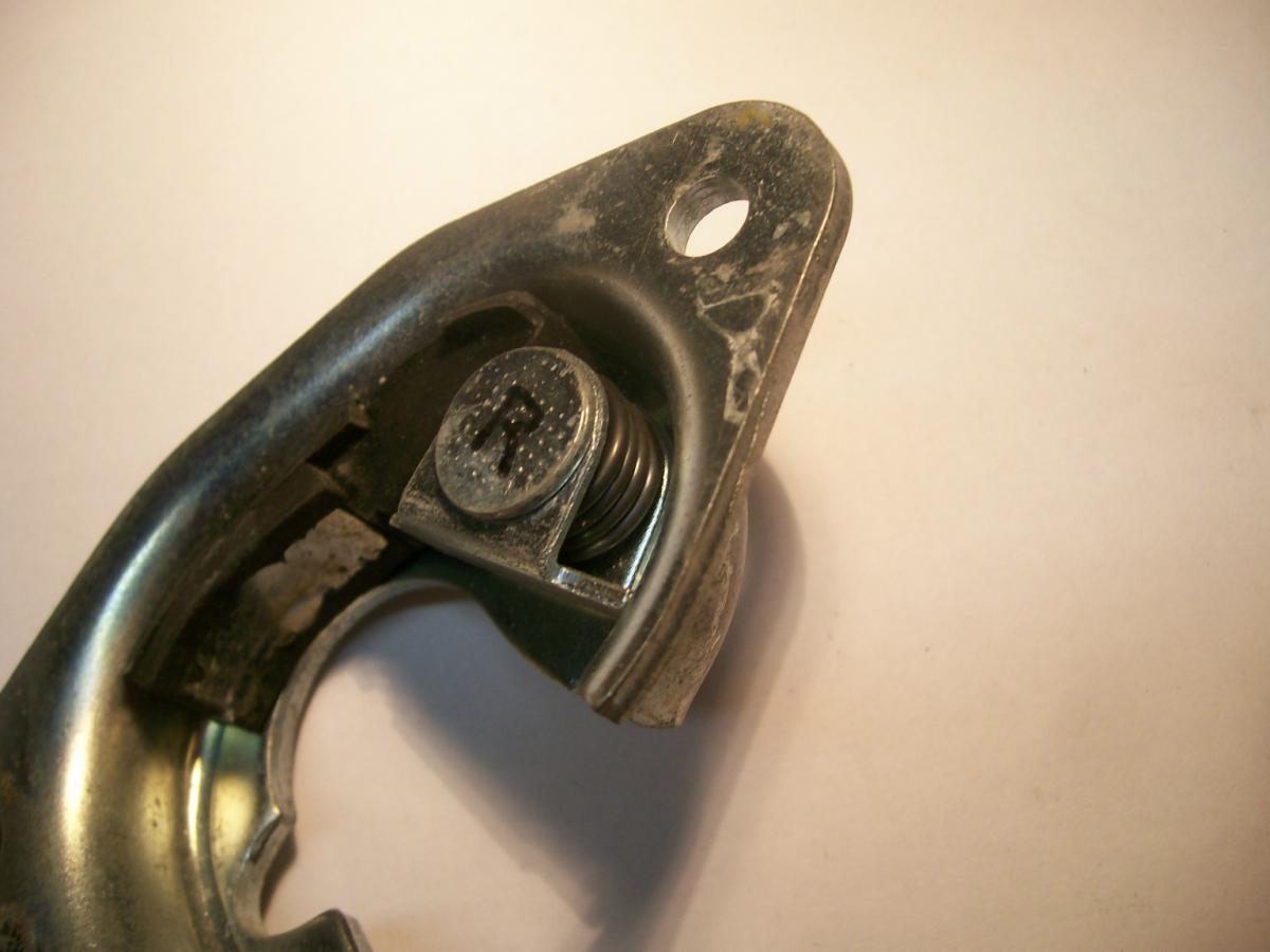
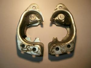
Thanks, zCars. Interesting, but worrisome, to learn that the missing 'dangly rubber bit' is typical. If that's the case, then I would guess that most of the Z's on the road are missing this piece on at least the drivers-side door (MFS... Most Frequently Slammed). It would appear that the dangly rubber bit is the part that takes most of the impact when latch meets striker (as testified by the fact that it breaks off on the drivers side, but not on the passenger side). So wouldn't the loss of the main impact-absorbing piece be a bad thing? I guess the only way to tell would be a 'door slam comparison test', using striker plates that do and do not have an intact rubber cushioning block. Not likely to happen, I suppose. BTW, I still don't understand why there's a spring. Are you telling me that you think the rubber block is supposed to pivot on the mounting pin? If that's the case, is the block supposed to pivot out away from the plate frame in the door-open condition and then get pushed back flush against the frame when the lobe on the door latch hits it? Any door latch experts in the audience?
-
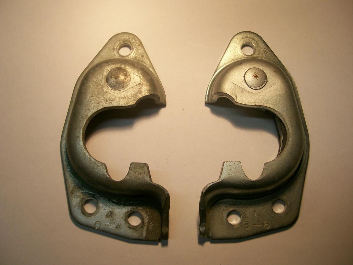
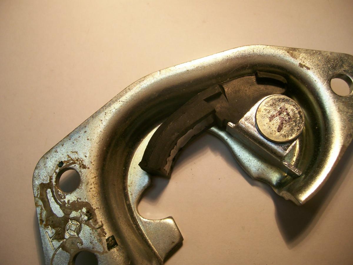
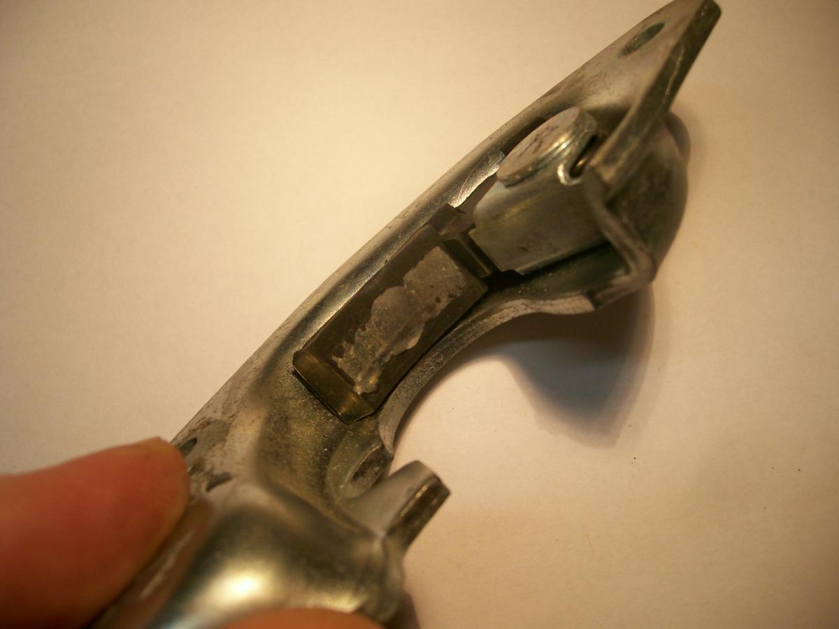
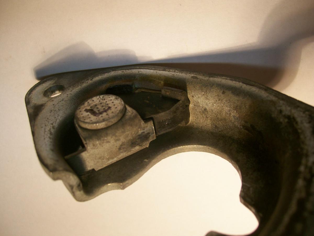
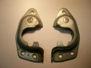
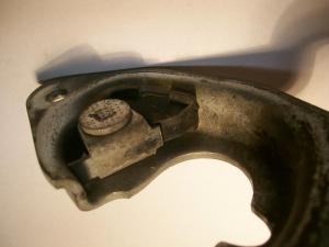
I happened to be looking at my '70 Z's door striker plates (aka 'door catch') the other day and noticed, for the first time, that they're not as simple in design as I thought. It had always been my impression that they're just one-piece metal stampings. When I turned one of them over, I discovered that this isn't the case at all. They're actually pretty complicated in design and construction, consisting of: Main stamping Cushion Block (rubber molding with a metal insert) Mounting Pin & Spring for Cushion Block Mounting Boss (metal stamping) for Cushion block I'm not really sure how the cushioning block arrangement is supposed to work. Any efforts to make it pivot on its mounting pin have been unsuccessful, so I'm not even sure if it's supposed to move in the first place (but then, why is there a spring? and why does it appear that there's a metal tab on the mounting boss to set a 'rest' position?). Note: In the third picture, I levered the 'leg' of the cushion block away from the striker plate surface to show the amount of flexibility it has (i.e. the leg's displaced position wasn't generated by the cushion block pivoting on its pin). Normally, the 'leg' rests on the inner surface of the striker plate, as shown in picture #2. In addition, I'm not sure whether either of my striker plates has a fully-intact cushion block. As you'll see from the last picture, the cushion block for my left-door striker plate has broken off up near the pivot pin. I'm not even certain that the cushion block on my right-side unit is still its original length. Notice how the rubber has worn off on the 'intact' cushion block to expose the metal underneath. This would be the place where the latching lobe impacts and sits when the door is latched closed. So, two questions: 1. Does anybody have a picture of a NOS striker plate that shows what the cushion block looks like when it's new? 2. Can anyone explain how the cushion block is supposed to work? (i.e. Is it supposed to pivot and, if so, how much? If not, why is there a spring?)


-
The swap meet organized by the Ontario Z-Car Club back in October had at least one set of Z doors in v. good condition that did not sell. Hood, I'm not so sure about (they're a little more difficult to haul back and forth to events). Bottom line is that these parts are still out there. I think that if you post a want-to-buy listing on the parts-for-sale section of the larger owners club sites, you'll find what you need pretty quickly -- and probably at a good price, too.
-
Niles Co. - still in business... Niles Co., Ltd. - ProfileNiles has been developing and manufacturing switches and other electronic components for automotive use ever since its establishment in 1954. Born just over a half-century ago in Tokyo’s Ota Ward, Niles has developed into one of the leading automotive electronics component suppliers in the world, with sales, engineering and manufacturing bases in Japan, the US, Europe and Asia. We at Niles are truly grateful for the support and patronage from all of our business partners over the years. Our outstanding reputation for quality and technology have been embraced by auto manufacturers and automotive systems suppliers around the world. We at Niles understand that our customers expect only the best from Niles, and we are poised to meet the challenge. N.I.L.E.S. = Nippon Instrument Light & Electric S___ ? (just a guess) Maybe somewhere at the back of their warehouse, there's an unopened carton of brand-new Z inspection lights!
-
I'd like them back now, please.
-
Thanks, Chris.
-
I noticed today that MSA has begin to offer refurbished differential hanger brackets on an exchange basis. In their write-up on these new parts, they discuss applications in relation to solving the differential 'clunk' problem and emphasize that Series 1 owners will need to install the Series 2 differential hanger parts and moustache bar in order to be able to use the Series 2 front insulator (I believe that this is because the arrestor strap won't fit otherwise). This made me curious, so I started to look around some of the commonly-used parts vendors' websites to see if anyone was offering the Nissan Series 1 part (PN 55415-E4102, for reference). A quick look turned up 'not available' at Rock Auto and Chesapeake Nissan. Z-Car Source of Arizona offers only used units, and only on special order. Courtesy Nissan lists the part and a price, but that doesn't mean they have it or can get it (I haven't asked them yet). MSA lists it, but warns that it "...has been discontinued by Nissan or another manufacturer, and we are currently in the process of locating an alternate supplier or having the item reproduced" So: Is a new OE Series 1 diff mount/insulator definitely NLA ? If so, are there any known aftermarket options?
-
The failure of the rearmost manifold stud seems to be common to the Z L-Series engines and it's the bane of a lot of Z owners (i.e. welcome to the club). Your ex-Nissan friend's statement that the cause comes from rearward shift of the manifold is interesting -- many have speculated on why this particular stud shears off, but I'm not sure I've ever heard exactly that explanation before. In the end, though, 'why' doesn't really matter. You need a solution. Because I have to deal my the same problem with my '70 (and I'm about the same age as you), let me think out loud for both of us: Note: Everything I say below is premised on the assumption that the stud is sheared off flush with the surface of the head, so that there's nothing left to grip on. Solution #1: Remove the stud using heat and an EZ-out. As noted by Patcon, the intake and exhaust manifolds are going to need to come off. Then you'll need to drill an accurately-centered/directed hole into a small-dia stud and use the smallest-dia ez-out in your toolbox. From my experience, this is a certain recipe for disaster. It's going to be hard to get that hole drilled accurately with the engine/cyl head still in the car. I predict the end result will be an ez-out snapped off inside the stud. Now what do you do? Solution #2: Forget about trying to drill a hyper-accurate hole and forget about using an ez-out, too. Forget about trying to save the old threads. Just drill a reasonably accurate hole into the stud, then keep stepping up the drill bit diameter until you've taken out all the stud material and created a hole in the aluminum head casting suitable for tapping for a next-oversize stud. I believe this is the most common solution, historically. You may want to wait to hear what others have to say about this, though. Solution #3: Remove the head and take it to a competent machine shop. There's an element of trust involved in this approach. You may end up with an oversize stud anyway (see #1, above). Solution #3: Remove the head and try the ez-out strategy, taking advantage of better access to drill an accurate hole and apply directed heat. Good luck with this. I've recently tried to get a snapped-off mounting stud out of a Honda windshield wiper motor casting. The stud has a 6mm thread. The motor/casting was sitting on my bench in a vise, so I had perfect access. I pre-soaked the stud with repeated applications of acetone/ATF for over a week. I applied heat repeatedly for over two minutes. I even tried cold-shock, using an aerosol spray-cold fluid. Result: On my sixth cautious attempt to get the stud to move, my name-brand ez-out snapped off inside the stud. I might have had a better result using an oxy-acetylene torch for heat, but I don't have one (and it probably would have fried the wiper motor wiring anyway). Solution #4: Remove the head and take it to shop that offers 'metal disintegration' services (also known as 'electrical discharge machining' or 'spark erosion'). Good news: You'll get to keep the original threads and stud size. Bad news: According to others, It's going to cost you $200 - $300. Can anyone else confirm? Solution #5: Remove the head and replace it with a used one. Z cylinder heads seem to be dirt-cheap. Of course, you'll need to be sure that the one you get is straight and not damaged (check the cam lobes for good wear patterns). It may need new valve seals (but then, the one on your engine may already need these anyway).BTW, all of the head-removal strategies are going to require ponying up for the cost of a gasket kit. Comments, anyone?
-
That's a great resource. Lots of time invested by the owner of the site. Now I know where the wire stand for the oil pressure sender unit goes!
-
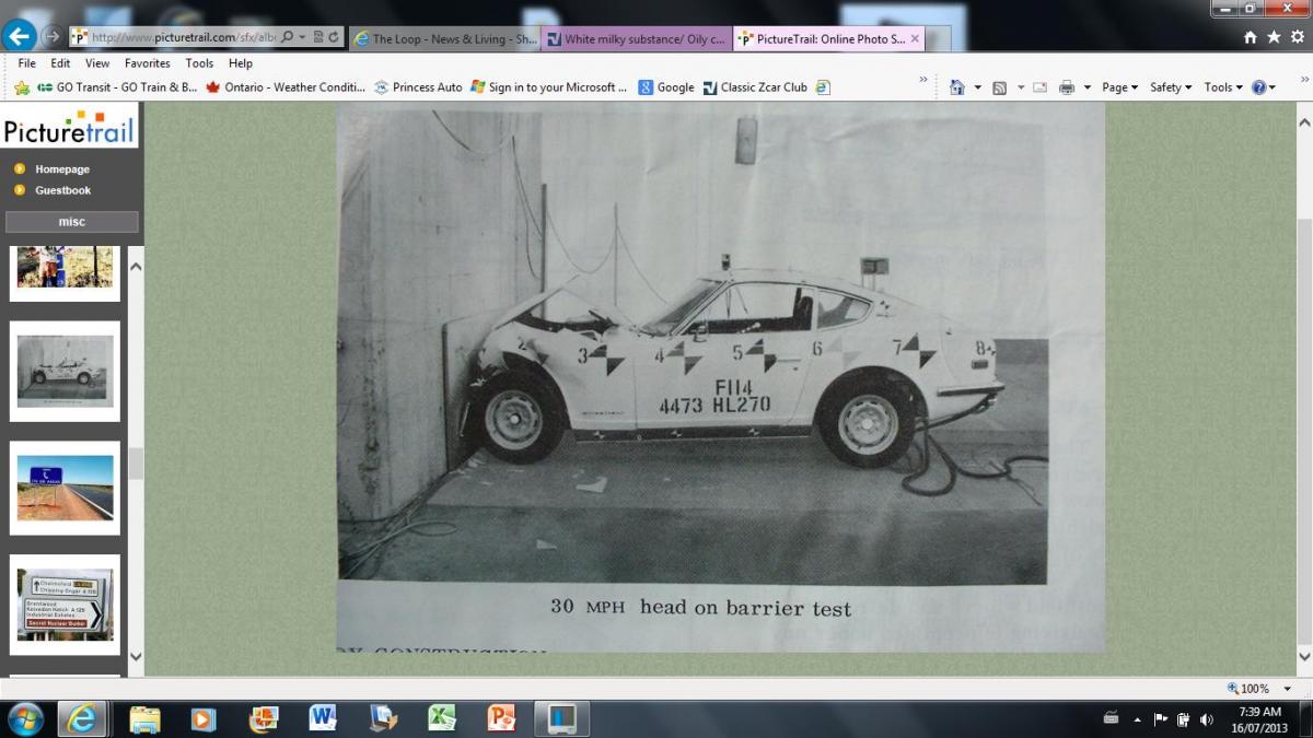
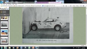
Crash test results for the Z. One by Nissan, pre-production. The other by U.S. government testers. Both, I believe, at 30 mph. In my opinion, the most important thing you should attend to is the condition of the car's seat belts and their mounting points. Forty-year-old seat belts are not a good idea. First, the material characteristics can change over time (exposure to sunlight UV rays and air pollution). Second, the webbing may have become damaged (frayed edges, mini-nicks, etc.). It will be very difficult to find 'new-old-stock' Nissan belts. Most Z owners look to either Wesco Performance or Motor Sports Auto (MSA) for new, replacement belts. These have the additional advantage of providing brand-new retractor mechanisms (unlike the forty-year-old items in most Z's, which are likely not too happy about retracting smoothly). New seat belts are inexpensive insurance against being thrown out of the vehicle or going through the windshield in a crash. They're also important in that they let you and your body 'ride down the impact' by absorbing your forward energy as they stretch under load. You may come out of a crash with some black-and-blue marks, but that's better than the alternative. Of course, new belts aren't much good if any of the mounting points have deteriorated. Unfortunately, that's a problem area with a lot of Z's, since the lower outboard mounting points for the belts is situated in a chronic rust area (that's also difficult to repair properly). Have this inspected by somebody competent.

-
Having seen the pain that others have gone through for this particular job (Exhibit A: Blue's write-up on the Atlantic Z-Cars site; Exhibit B: Hardway's write-up on this site), I don't think there would be an issue with $80 - $100 for this tool -- if it proves to be effective. The big socket would only add another $10 or so.
-
Puzzle solved (unless that extra '012' stud shows up in another location on the engine!). Or maybe Nissan already knew that the rear stud was going to break on 90% of the L-6 engines they produced and decided to equip each car with a spare .
-
I'm still confused. For the '013' studs, I assume that these are for the outermost holes at the front and rear of the head, each of which also serve to locate an engine sling/hoist plate (this agrees with the fiche/e-fast, which says 2 required). I agree with the count of 6 required for the '014' studs. However, for the '012' studs, I count a total of 6 + 3 = 9 required (fiche/e-fast says 10 required). So, which is correct: 9 x '012' + 2 x '013' ? or, 10 x '012' + 1 x '013' ? Or is it something else?
-
When installing my new vinyl seat covers (made by Distinctive Industries, bought from Banzai Motorsports), I discovered that the cover for the 'cushion' (bottom) part of the seat is sized specifically for the aftermarket replacement foam. That aftermarket replacement foam bottom piece is molded so that it's about 2 cm taller ('thicker') than the original Nissan foam. This was only an issue for the bottom part of the seat. However, you can't buy the top and bottom foam pieces separately. I was able to get proper fit with my old Nissan foam (which, on my car, was in remarkably good shape) by putting a 1-inch-thick slab of upholstery-shop foam under each molded bottom piece. Nevertheless, for best fit, my experience suggests that new seat covers should be accompanied by new seat foam. I expect that the leather seat covers will also be sized for the aftermarket replacement foam. Maybe somebody who's bought the MSA or Innovative Industries leather covers can comment.