Namerow
Community Member
-
Joined
-
Last visited
Everything posted by Namerow
-
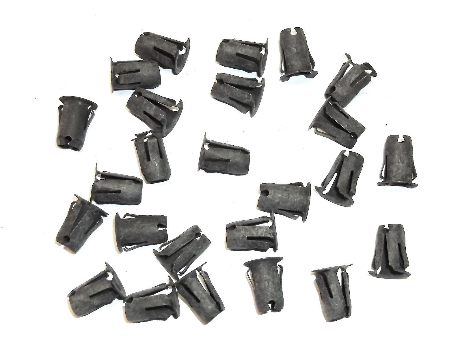
When I bought my Z from the PO, the body had been repainted and all of the small press-in clips used to secure the trim badges had been removed and lost. Now that I get around to replacing them, I find that I need 20 of them and they cost $2.50 each. That's $50 for a bagful of clips that I would have expected to be worth five bucks max (ok, maybe ten). Has anyone located a non-Nissan source, or a parts-store substitute, for these pieces? In Nissan parlance, these are: 'Clips - Tublar' (tubular) with the part number, 63845-18000 . In the non-Nissan world, I believe these are called 'trim barrel nuts'. Everybody used to use them back in the day. I think these are what the Nissan clips look like...

-
This is an impressive build. Great attention to detail. I like the fact that you're willing to divert from the conventional aesthetics here and there (e.g. black fasteners) to get the look you like. I didn't track back through the entire thread to pick up on the details, but I believe there was discussion of electrical tape. May I suggest that you have a look at using automotive 'loom' tape (no adhesive), rather than the non-automotive. Maybe not so important for the under-dash wiring (where covering the wiring runs with tape is probably optional), but a real consideration for the engine compartment, where engine heat can cause the tape adhesive to weep out of the wrap, creating a dirt magnet that will defy easy clean-up. I used loom tape to re-wrap my engine compartment harness (pretty much all of it, by the time the job was finished) and was really pleased with the results. There are some tricks to working with this material but, with a bit of practice, you should be able to complete the job in a morning or an afternoon. A $25 roll should be enough for the front part of the car. If you're interested, I'll post some hints on how to do the wrap.
-
Well, I meant electrical, of course. Chemical engineers just play with reactions and stuff. Nothing useful.
-
IIRC, there was a vendor in Victoria, BC who offered Brit-style jute by the yard. Knowing the Brti car community on the lower Island, I don't think they'd tolerate anything that wasn't absolutely 'pucka'. Maybe worth investigating. Alternatively, just 'go to the well': Britain. That was Nissan's inspiration for a lot of things in the early days ('My Fair Lady')..
-
OK, this -- along with the socket-head cap bolts substitute -- wins my vote for, 'best improvised maintenance fix of the year'. If you'd been a Nissan Service employee when these cars were in production, CO, they probably would have given you an award! Who said chemical engineers can't think outside the box?
-
It's been done, and documented with photos... somewhere (where?) on this site . Is that strands of fibreglass I see across a hole at the bottom of the A-pillar? Yikes!
-
There was a good discussion here recently about sources for authentic jute (The Roadster Factory... http://trf.zeni.net/webcatalog/specials9.35/38.php?s_wt=1680&s_ht=1050 ) and OE-matching early-style carpets. Can't remember the carpet mftr's name (I think it was brought up by Jim Arnett). Do a search on 'Careless'.
-
According to my notes, these were the changes to the carbs that occurred as of Jan. 71 production and the emergence of the so-called Series 2 cars... Different, front vs. rear… Front = long-ear, long-needle; Rear = short-ear, short-needle. Drain fittings added. 3 screws for float bowl covers. (S1 carbs used 4-screw float bowl lids, with long-ear / long-needle for both front and rear. Bowls did not have drain fittings.) For the 72 that I no longer have, the carb re-build kits that I bought had entirely different part no's.
-
I found Eastwood's 'DuraBlock' sanding blocks to be just about ideal for the contouring of my S30 dash. The big, teardrop-shaped block got the most use. Perfect for the big-radius valleys between the gauge pod humps. IIRC, I had to use a small length of heater hose as a block for certain areas (inside lips of the small gauge pods, maybe). I had the same problem with the bumper repair compound (I used 'Bumper-Bite'). I recall having only about 45 seconds available per mix before it began to set and could no longer be shaped or smoothed. Even cutting the ratio of hardener-to-base down to 1:10 had no effect -- the stuff just seemed to be ultra-sensitive to the hardener catalyst. I only used it to finish off my localized repaired areas. I can't imagine trying to use it to cover the entire dash surface!
-
As one of the PO's of this car, all I can say is that I didn't know about these specific rust areas... but I suspected there'd be stuff like this lurking under all that undercoating. Anyway, Grannyknot is an artist with a MIG welder, so this should be quite fix-able. Chris: PM sent
-
Does Bender know about this?
-
I spent a lot of time reading other contributors' write-ups before tackling my cracked S30 dash two years ago. I don't recall anyone who had tried applying the flexible bumper repair compound over the entire surface of the dash. I can see some possible attraction, since it would theoretically put a flexible cover layer over the vinyl-to-filler seams that everyone worries about splitting apart after the dash has been put back in the car and exposed to the elements. However, it seems like the equivalent of applying body filler over an entire hood panel just to deal with a few localized dents -- you'll be setting yourself up for a massive sanding and contouring challenge. That said, I do recall one or two people who covered their entire S30 dash with fibreglass for exactly the same reason (and ended up facing exactly the same challenge afterwards).
-
I remember someone else promoting the benefits of LH drill bits. I hope to give this a try sometime, but first need to buy a couple of them (not available at your average hardware store) -- prob. one for M8's and another for M10's. One of my perennial problems, though, is positioning and then punching an accurate centre mark, and then keeping the bit from drifting out of it. I always seem to end up with a hole that's 10 - 15% off-centre. Not sure if it's bad marking technique, bad punching technique, wrong drill-tip shape, or bad drilling technique. Maybe it's all four!
-
Give me a day or two to pull some pictures together.
-
I had a quick look at the TPP website and found some interesting info (assumed accurate) about zinc and cad plating and chromates... " Zinc plating is a soft, decorative, corrosion-resistant finish. Zinc protects the substrate by sacrificing itself and thus corrodes before the base metal. This means that zinc will protect even if the zinc coating sustains minor damage, such as scratches or small punctures because of the galvanic protection of the zinc; however, the zinc coating can be attacked or dissolved by ordinary liquids such as soft drinks and vinegar. The ultimate corrosion resistance of zinc is dependent on the thickness of the coating. To increase the corrosion-resistance of the zinc, a conversion coating is usually added. The primary use of chromate finishes on zinc is to retard or prevent the formation of white corrosion products on zinc surfaces." 'Attacked or dissolved by ordinary liquids such as soft drinks or vinegar' !!! I'm going to try this on one of the parts that I've already plated (poorly) to see what happens. Also: It looks like the max. target thickness for commercial/industrial zinc plating is 0.001". TPP has the following to say about cadmium plating (which they apparently still offer): " Cadmium plating is generally bright silvery white. Supplementary treatments for type II can be golden. iridescent, amber, black, or olive drab. The corrosion resistance is very good, especially with the type II finish. Cadmium plating is still the preferred metal over zinc, in the aerospace industry. This is partly due to its excellent adhesion properties for painting, and it can't be stripped off as readily as zinc. Cadmium is excellent for plating stainless steels that are to be used in conjunction with aluminum, to prevent galvanic corrosion. TPP offers the following chromate conversions for cadmium: Clear, Yellow, Black and Olive Drab. Parts with a hardness greater then Rc-40 shall be stress relieved prior to cleaning and plating, and should be given a hydrogen embrittlement relieve post bake." Interesting that there's no mention of post baking (re hydrogen embrittlement relief) in their discussion of zinc plating.
-
Thanks, Patcon. This is really helpful. Success with this process seems to be really dependent on uber-cleanliness and getting all the details correct (hence the long list of detail-y questions ). I just made a sweep of the Dollar Store yesterday after work to pick up a new set of virgin pans, pails, buckets, and spray bottles. I'm going to create a fresh acid bath and bust out a brand-new wire wheel, too. Taking no chances!
-
-
The consensus at Z-Fest was that the best route to plating success might be for us to send all of our parts to you! I have a lot of questions (apologies if you've covered some of this earlier) How would you describe the nozzle setting you're using to spray your rinse water after the yellow chromating step: 'mist'? 'jet'? Or somewhere in between? Are you heating your electrolyte bath? What temp? Are you heating your chromate dip(s)? What temp? Are you using a bubble-stream agitator in your electrolyte bath? What acid concentration are you using for the pickling step? Have you been using the Caswell brightener in your electrolyte bath? Any signs detected yet that it may need refreshing? Have you been taking any special steps when plating parts that would be susceptible to 'corner' effects? What are the approx. dimensions of the wet part of your electrolyte bath? (I'm assuming your using a pail, so that would mean diameter and depth of fluid volume) What is the layout and approx. total wet surface area of your zinc anode plate(s)? (I'm assuming that only one surface would come into play, so a single plate with wet surface measuring 4" x 6" would equal 24 sq.in. rather than 48 sq.in.). I'm trying to get an idea of the ratio of anode surface are to electrolyte 'wall' area, as well as how you've placed your anodes. Are you taking any special measures to clean or polish your anode plates between plating sessions? Are you using a metal wire wheel or a fibre wheel to dress your parts before final cleaning? If your cleaning process involves a solvent, what solvent are you using? Are you taking any kind of de-rusting measures other than media blasting and wire/fibre wheel? (e.g. chemical/'Evapo-Rust, or electrochemical) When you've determined the amps setting you need for a given batch of parts, do you: 1) simply adjust the power supply setting up to this level and then connect to the part, or; 2) perform '1' as a starting point only, followed by using the read-out from an ammeter hooked into the circuit to do the final setting? (In other words, you've said earlier that the amps need to be set at the power supply in a no-load condition, but it would seem to me that the actual current flowing will change after a load -- i.e. the part and the bath -- is applied.) Looking at the overall process, when is the last time you actually touch a part with your hands? (I'm guessing that it's when you hook up the wire that will be used to suspend the part in the various baths and dips).
-
Just the basics: Electrolyte, brightener, blue chromate and yellow chromate. Only enough for a 1.5-gallon tank, but these cost close to Cdn $200 and that's about all I'm prepared to spend on this adventure. I still need to buy several small plastic pails for distilled water dipping. I've read some comments about not sharing the distilled water bath from one step to another, so I'm going to use separate baths for each step along the way. I'm also going to buy a squeeze dispenser that I'll use after each water bath, just to make sure that the part isn't carrying any residue from the bath into the next step (Caswell says to rinse the part in fresh cold water). I'll get at this next weekend, while I've still got the use of Grannyknot's controllable amp/volt power supply. I may have some questions for you during the week as I get closer to being ready to start..
-
Just keep in mind that it may have a shelf life, due to the acetone evaporating away over time (leave a small bowl of acetone out sometime and see how fast it vanishes). Although I've used this DIY mix, I can only say that it doesn't work any worse than any of the other penetrating oils I've tried -- and it costs a lot less. Overall, though, I had only limited success any of the penetrating oil (and WD40 is useless). Fasteners that have finally been coaxed free using an impact tool showed very (very) little oil penetration below the surface, even after repeated applications and having sat for days beforehand. I like heat (controlled) and impact (also controlled). That's just my experience, though. Your results may vary.
-
We had a short but lively discussion about electroplating at Z-Fest yesterday. I've now received my shipment from Caswell and I'm getting ready for what I hope will be my final (and successful) attempt. I'm pulling my notes together before getting started. Thought you might be interested in what I've learned about three topics that don't seem to be well understood: chromate dips, acid pickling, and hydrogen embrittlement: Chromate Dips Aka ‘chromate conversion’... The effect is called ‘passivation’ The purpose is to create corrosion resistance for the underlying metal surface. The zinc from electroplating is intended to provide corrosion resistance for the underlying steel part. However, the chromate is applied to provide corrosion resistance for the zinc (which is susceptible to tarnishing and becoming dull over time). ‘Passivation’ involves creation of an outer layer of shield material that is applied as a microcoating, created by chemical reaction with the base material. The technique involves the application of a light coat of a protective material (such as a metal oxide) to create a shell against corrosion. Passivation strengthens and preserves the appearance of a metallic surface (like zinc). The tarnishing of metallic surfaces is a natural form of passivation, called ‘corrosion coating’... When exposed to air, many metals naturally form a hard, relatively inert surface (e.g. silver ‘tarnish’). Corrosion coating (tarnishing) reduces the rate of corrosion of the underlying metallic surface. The thin, hard and relatively inert outer shell of corrosion inhibits deeper corrosion. The protective effect varies, depending on the kind of base metal and the nature of the surrounding environment. At room temperature, the protective effect is notable for aluminium, chromium, zinc, titanium, and silicon. When corrosion coating (aka tarnishing) occurs, the inert surface layer -- termed the ‘native oxide layer’ -- is usually an oxide or a nitride. For aluminum, even after several years, it will have attained a thickness of only about 50 Å. Pickling Pickling is a metal surface treatment used to remove impurities, such as stains, inorganic contaminants, rust, or scale from ferrous metals, copper, precious metals and aluminum alloys. A solution called ‘pickle liquor’, which contains strong acids, is used to remove the surface impurities. It is commonly used to de-scale or clean steel in various steelmaking processes. The primary acid used is hydrochloric acid, although sulfuric acid was previously more common. Hydrochloric acid is more expensive than sulfuric acid, but it pickles much faster while minimizing base metal loss. Hydrogen Embrittlement Hydrogen embrittlement becomes a problem for the pickling of some steel alloys and high-carbon steels. The hydrogen from the acid reacts with the surface and makes it brittle, leading to cracks if flexed… Carbon steels, with an alloy content less than or equal to 6%, are not very susceptible. Either hydrochloric acid or sulfuric acid may be used. Steels with an alloy content greater than 6% must be pickled in two steps and acids other than the usual sulphuric or hydrochloric are used. Substitute acids include phosphoric, nitric, and hydrofluoric acid. Nickel-chrome steels (which offer rust- and acid-resistance) are pickled in a bath of hydrochloric and nitric acid. It appears that some plating shops err on the conservative side on the matter of hydrogen embrittlement, recommending that any steel part that has been plated be heat treated afterwards if its going to see vibration or flexing in use.
-
Maybe a short step-by-step explanation of the re-and-re process (photos are nice) would encourage more tire-kickers viewers to become buyers? Maybe Grannyknot can do this as he works through his installation. As discussed yesterday at Z-Fest, this may be more about preventing bad stuff from going into the tank, rather than good stuff coming out of the tank.
-
Maybe he meant $8000 Canadian dollars (which would be roughly $6K US)? On the other hand, it's hard to find a good, rust-free S30 in these parts. You and your cars offer a degree of being 'pre-vetted' and US $7000 isn't an extreme price. This guy may be just trying for a knock-out bid so that he can bypass many of the unknowns that are usually part of shopping for and buying a rust-prone type of car from a distance. I'd take the chance and hear him out. Maybe keep it to email, though, until you get a better feel for what he's about. We have just as many scam artists here in Ontario as there are in any other part of the world.
-
I've had mixed success with freeze sprays. Worked like magic in one case (frozen brake line connection), but failed miserably in another (snapped-off distributor clamp-down bolt). In the latter case, I had the part on the bench and worked away at it for a week, using various sequences of heating, freezing, shock, and penetrating oil. I finally had to drill out the remainder of the stud and re-tap the hole for an oversize bolt). My theory (and that's all it is) is that the freeze sprays work well to break up ferrous-metal rust, but not so well to break up the thread bonding that occurs between dissimilar metals (i.e. aluminum casting / steel bolt). Nevertheless, your results may be different -- and I hope they are! One warning: Freeze sprays are quite flammable, so be careful about spraying a part that you've previously heated with a torch. You'll end up with a dandy little fire and you better have an extinguisher close by (ask me how I know this).
-
This past March, a friend of mine -- mid-60's in age -- contracted 'legionnaires disease' (legionella) and had to be kept in a medically-induced coma for over a month. It's been a long road to recovery, but she's now up and walking and working through daily rehab at the hospital to recover sufficient strength and mobility to be ready for discharge sometime in September. Your son is presumably younger and -- all other things being equal -- should be able to enjoy a comparable, if not more rapid, recovery. So, be patient, be positive, and reach out to others -- including your friends here at CZCC -- for your own support.