Leaderboard
-
HusseinHolland
Free Member6Points1,031Posts -
conedodger
Free Member4Points12,513Posts -
JDMjunkies.ch
Free Member4Points637Posts -

siteunseen
Free Member2Points15,115Posts


Popular Content
Showing content with the highest reputation on 01/02/2024 in all areas
-
It's done! After a few weeks of tinkering around i had it finished. Well, actually, quite a while ago. But it's finally time to show you some details. The kit took me approx 2 weeks of work every evening 1-2 hours. it's not too much of work, and pretty straightforward. the Manual is idiot-proof despite being in Japanese it's easy to make. The difficulty level is so-so. It will be tricky if you never used a screwdriver before. But for me, who didn't really have any experience with such kits it was doable. In my case the previous owner messed up a few things which i had to fix. The kit is intended to be only installed with screws (no glue!) but in some cases, it was nessecary to add some glue to make it more fixed. Some of the parts require quite some force to be installed, while being fragile at the same time. I broke 2 small things, but nothing a bit of superglue could'nt fix. At the end it's a super detailed model car of a Japanese Fairlady Z (with L20 engine). There is light, door light switches, brake pedal switches, many controls are movable (heater control knobs!), and it's pretty much close to the original car, from the chassis frames to all the engine bay and interieur details, it's absolutely incredible. It's a super fun project and well worth the hours spent: Here arew a few details. Frame rails and front axle with steering rack installed: All the lovely details of the L20 engine (yeah, you have to install every ignition wire manually!) Rolling chassis with transmission Propshaft and engine installed: Time for the interieur: Here's an example of all the details. the battery alone is for e.g. 17 Parts: And completed: Or look at the hood hinge: Incredibly close to the original design 12 screws for one hinge alone!! Some parts, like the door lock is as tiny as this: The window have an actual working crank mechanism: Body completed: Time to put it all together: This part was a bit tricky: Batteries for the interieur, headlights, brake lights, etc: And done, including the nice display stand: The interieur is really lovely: And all the details in the engine bay: The tools and towel that came with the kit (original tool pouch got lost by the previous owner): The spare screws, which are leftover at the end (each screw comes with at least one spare): It's not going to be my hobby and i had to swear more than once, but at the end it was a super fun project with a really nice result. And the magazines, dvd's and the car itself are well worth it.4 points
-
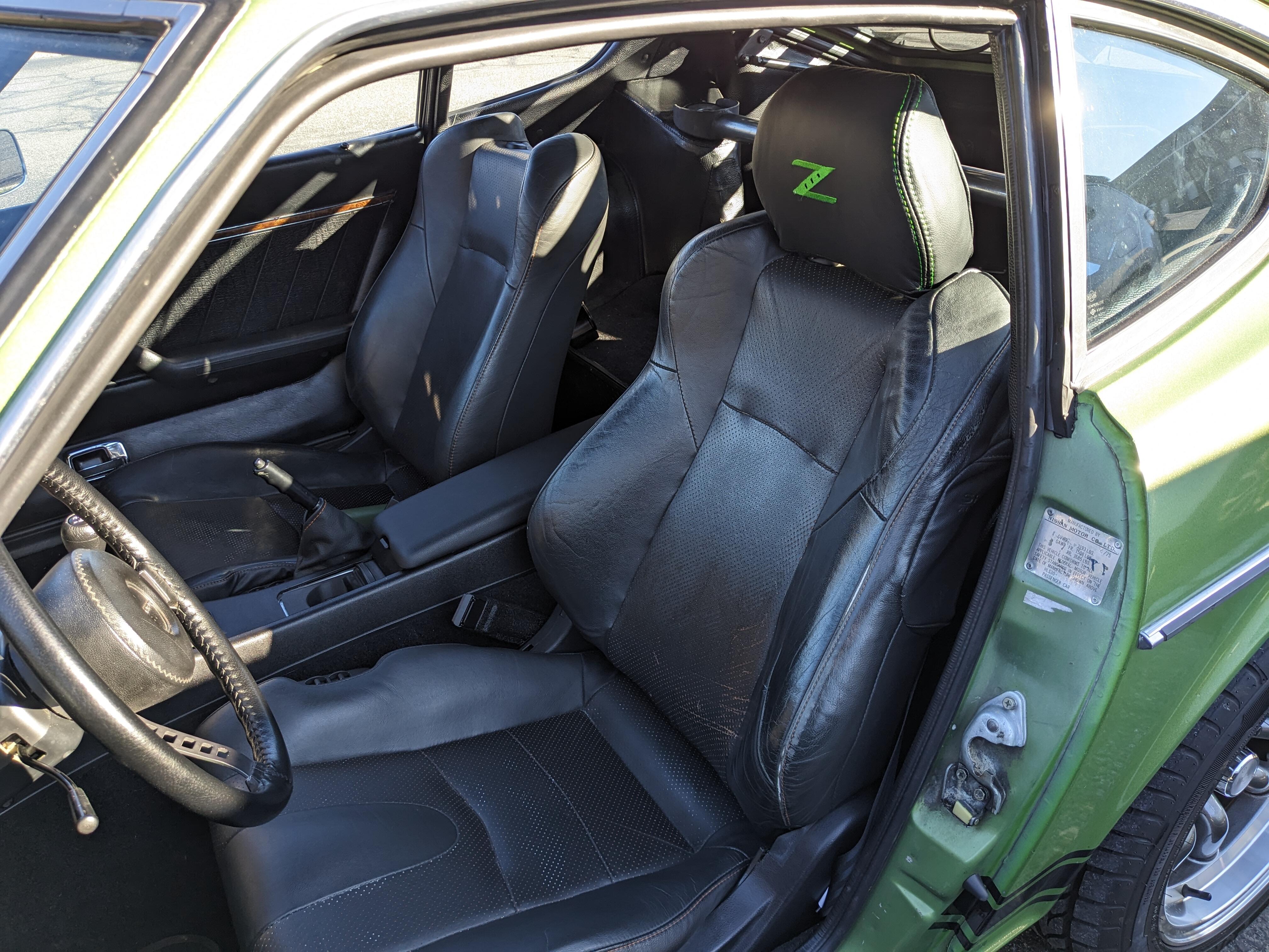
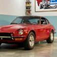
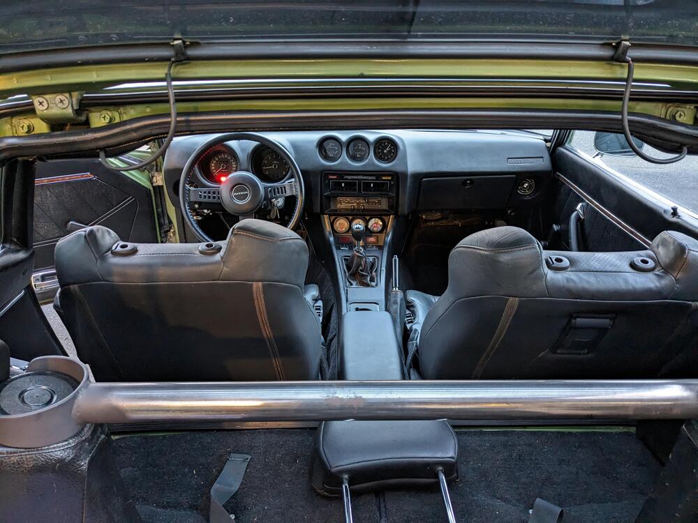
2 pointsDaytime pic with headrest. New leather for the seats has the same green stitching. I also went with a dark grey inset for the perforated panels. Not sure it's dark enough though. Seems more like a medium grey to me. Pics later
 2 points
 -
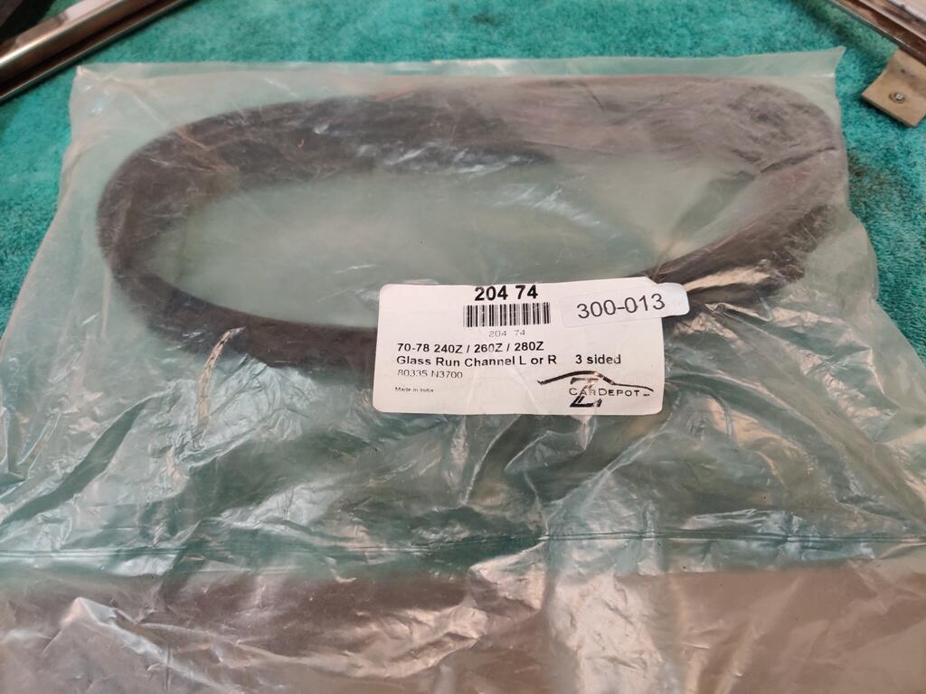
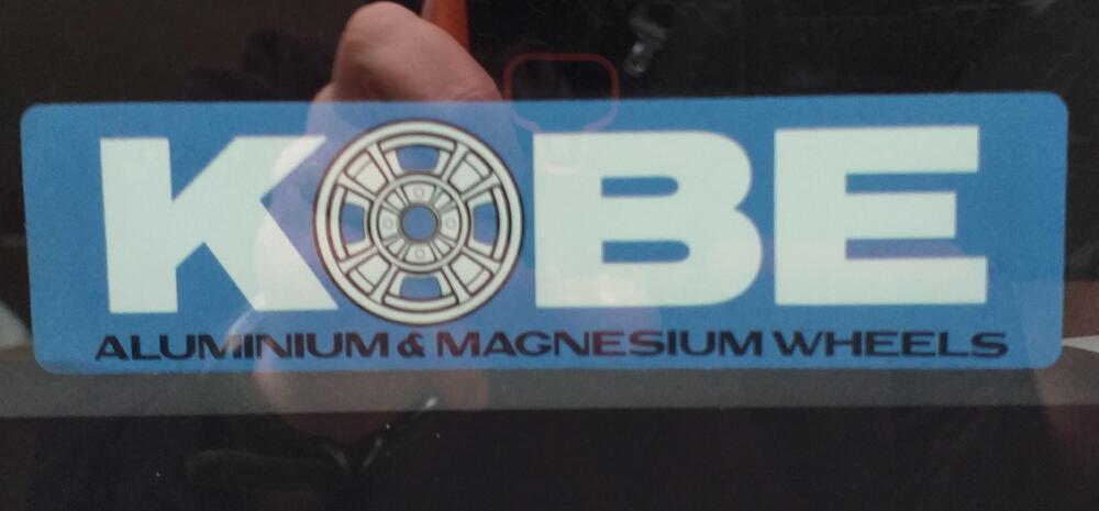
2 pointsAnd finally here is an image of the sticker on some car glass...
 2 points
 -
When you adjust the plastic part on the interior latch rod make sure you have enough play on the latch for when you put the door card on. If its too tight and the latch isnt completely releasing the lock will not work. I tightened mine up to take all the play out of the interior handle and when I put the door card on the lock wouldn't work......and it all had to come apart. Hope that makes sense. Good thing you installed the mirror before the glass. Its a pain to get on with the glass in place. Pro tip......The clips that hold the door card in place go opposite the little notch on the door card. 😀2 points
-
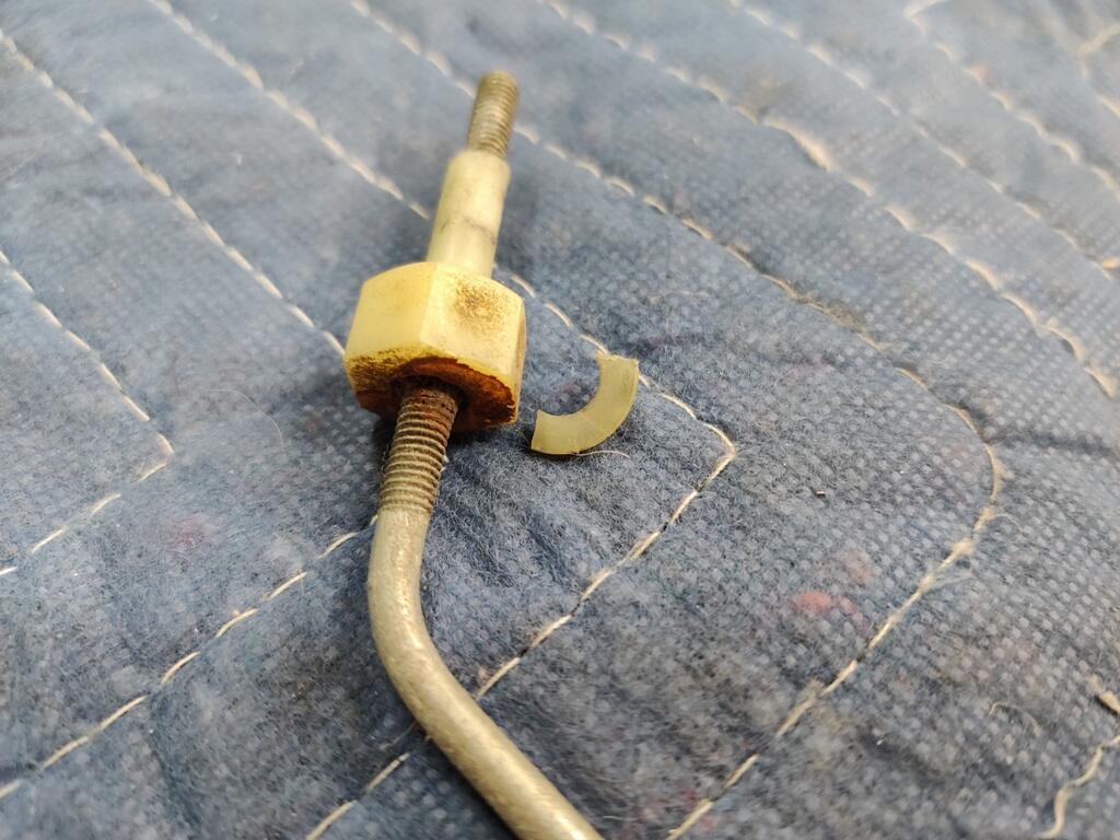
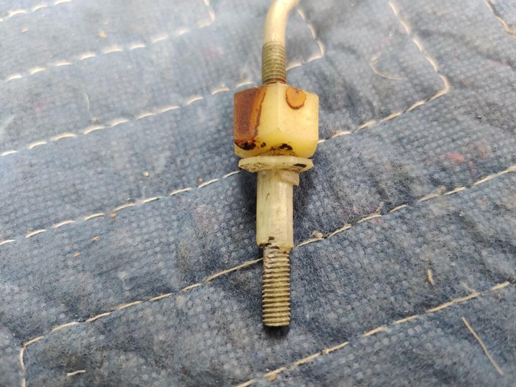
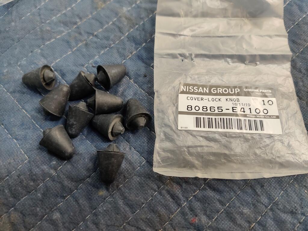
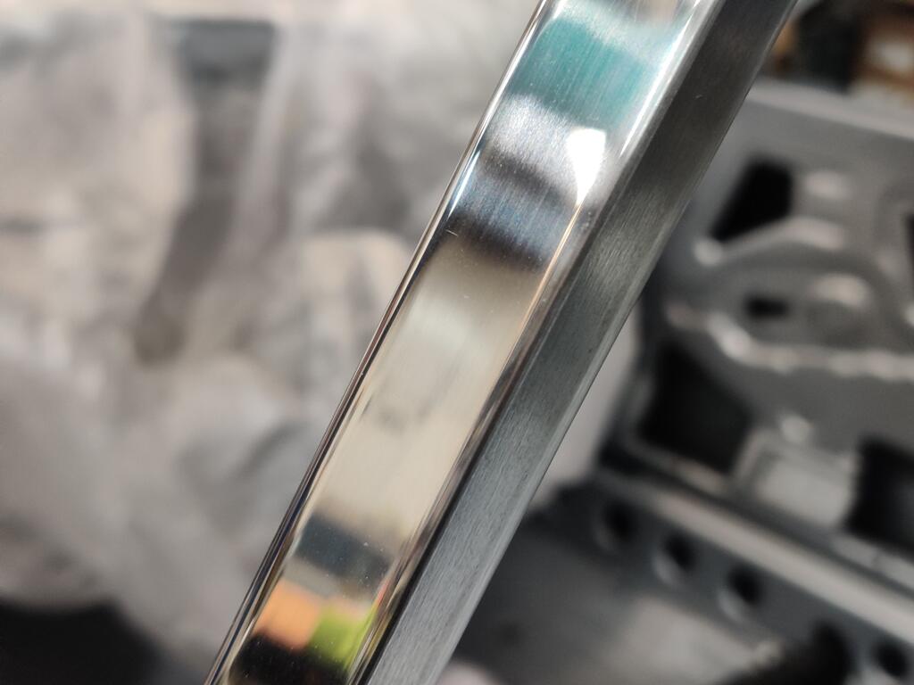
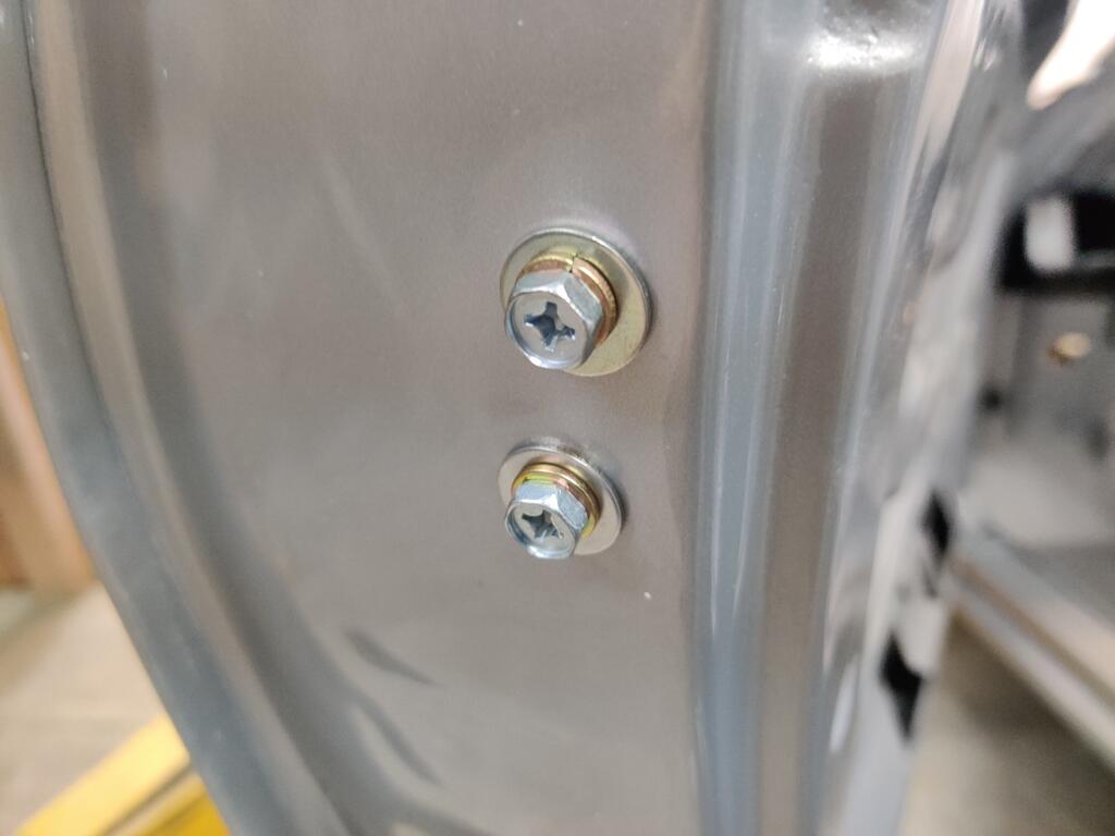
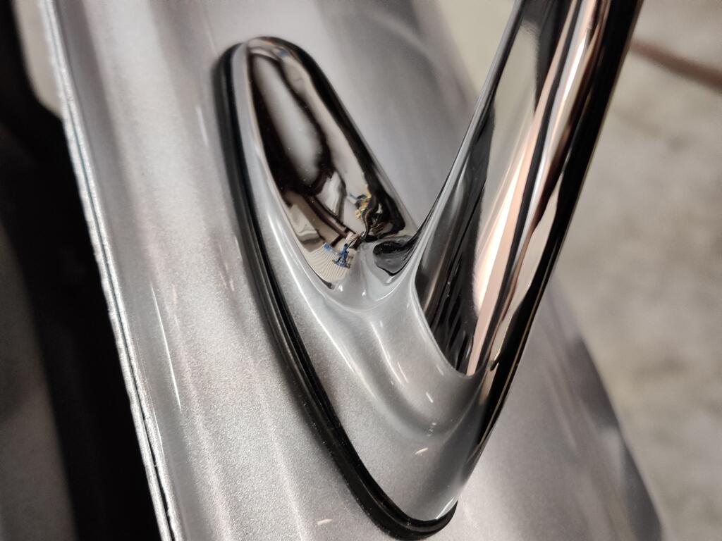
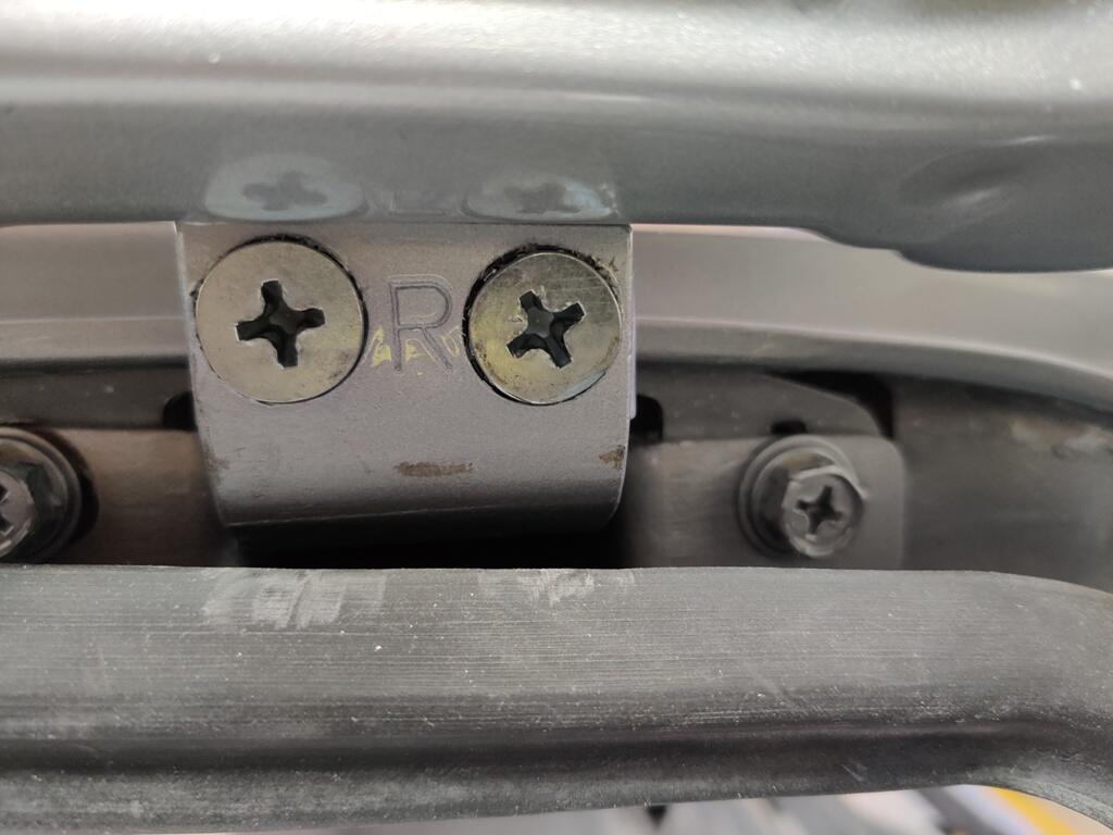
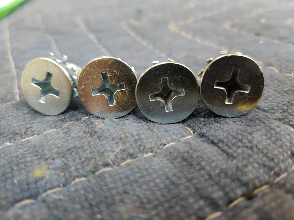
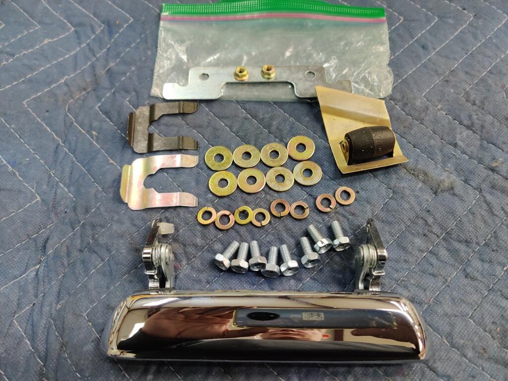
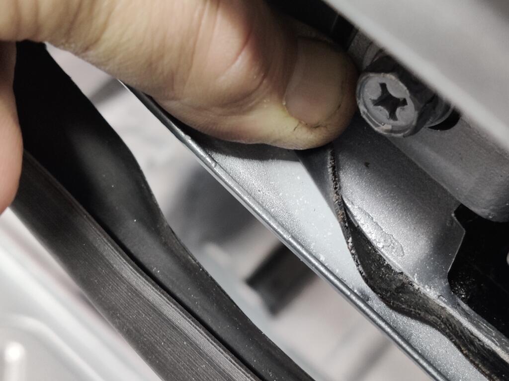
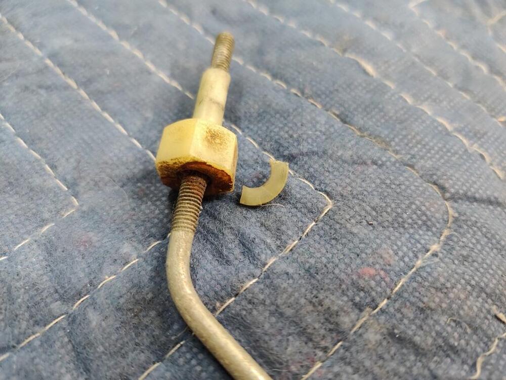
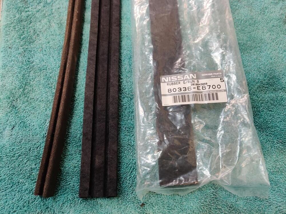
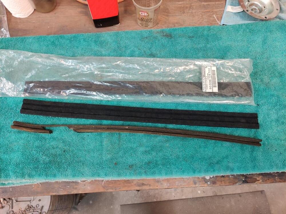
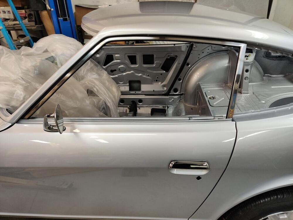
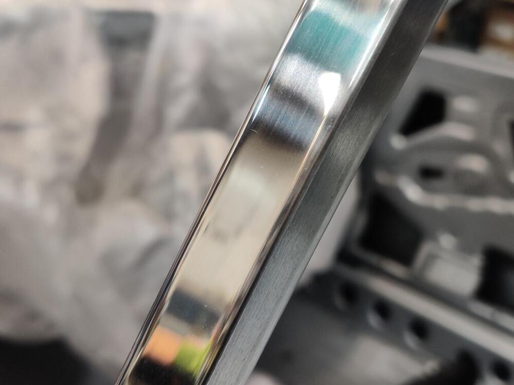
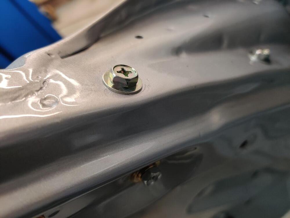
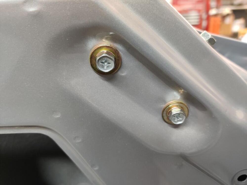
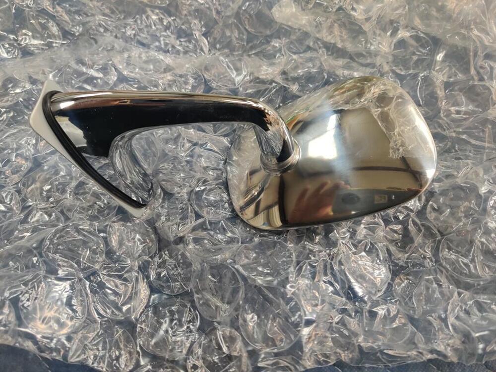
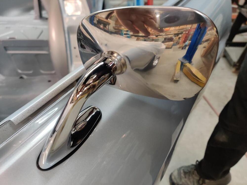
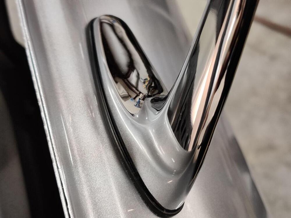
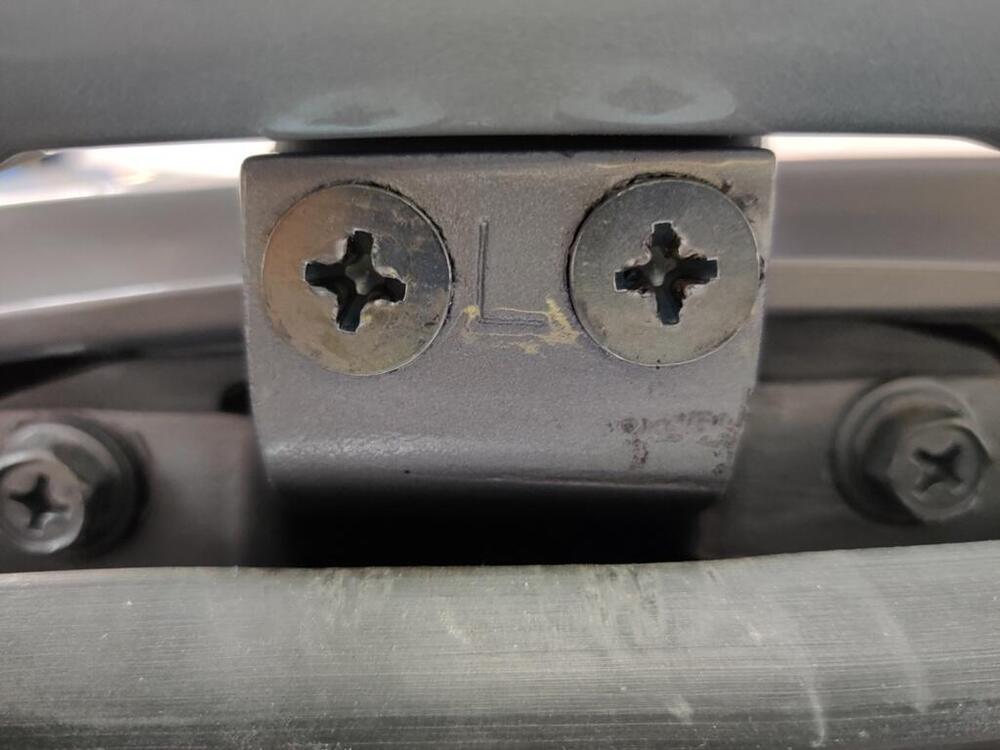
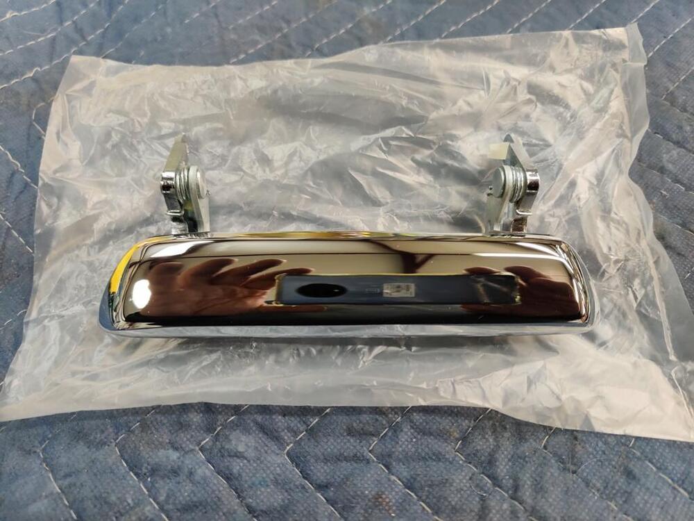
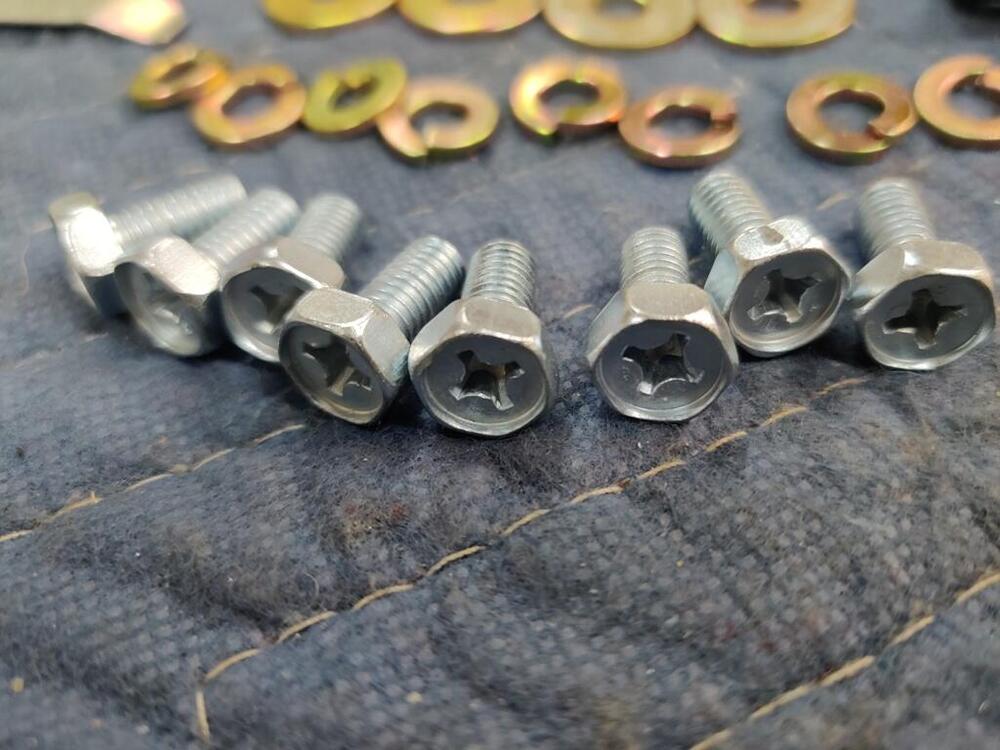
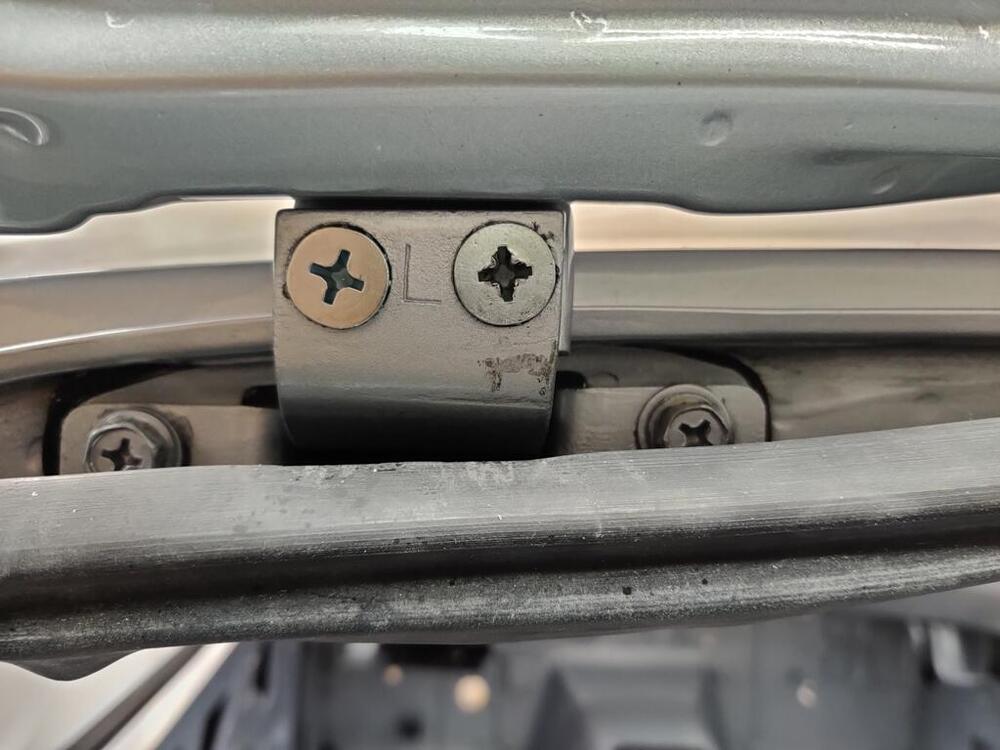
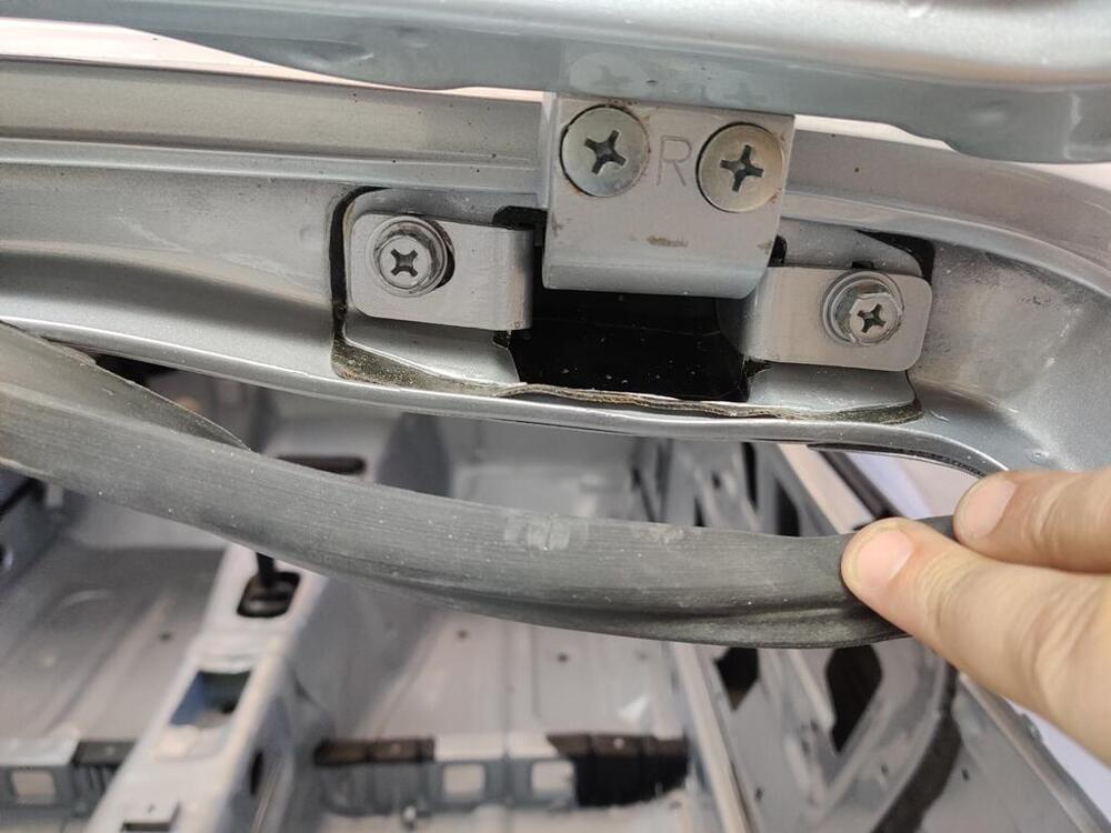
Here are some pics from the work completed this weekend. New factory original parts like this mirror and door handles are so nice to install! Little remnant of plastic piece (middle and third photos here) was a sleeve that sits on top of the door latch lever. When those disintegrate, the amount the door handle has to move increases. Obviously, you can adjust the height of the plastic part on this rod to achieve proper handle movement to operate the latch. I am second guessing the plating of the hardware for the bolts that attach the stainless window frame to the door shell. Yellow chromate on the washers isn't looking right to me. I think I have the original bolts here (clear zinc), but I think the lock washers and flat washers should also be clear zinc. Also, in the first pic here, I used some bolts that have a captive flat washer and no lock washer. I believe these are incorrect and I will have to swap them out. New window weather stripping is nice - it will make for some tight (and quiet) windows when they get installed. I mainly used 1000 grit on the stainless window frame to remove light scratches. I used 600 grit in a couple of places, as there were a couple of deeper scratches. Then followed with 1000, then 1200, then a light finish with 2000. I like the finish. You can still see some "grain" which is how the original finish appeared to me. I found another thing the body shop did that I was unhappy with. The hatch was not well aligned - the left side was a little low. I instructed them to align the hatch, and then remove only the hatch panel, leaving the hinges in place to be painted (as they did at the factory). I have no idea what they did here with the hinges. They didn't remove them to paint the inside of the hatch frame, as can be seen in the pic where I am lifting up the rubber hinge seal and you can see primer underneath. That is fine, and what I wanted, but why is the hatch hinge seal not painted, and yet the "seal cover plate" is? I don't know how they did that. The bolts securing the hatch hinge to the body were loosened and the hatch shifted/aligned after painting! I specifically wanted to avoid that. Now the paint on the bolts is chipped and there is an unpainted spot on the right hinge - you can see where the bolt was when the hinge was painted. And they managed to mess up the phillips screws... Fortunately, I had a spare set of screws on hand, so I swapped them out. Swapping out the messed up screw for a nice one (first pic below) makes a big difference cosmetically. Details like this matter to me. I wish this was done as I instructed. Live and learn. Next time, I will make sure I complete everything - everything, before I hand off for paint.


 2 points
 -
added the support bracket with two nuts to the driver's side of the strut brace. Have to do the pass side tomorrow, ran out of daylight

 2 points
 -
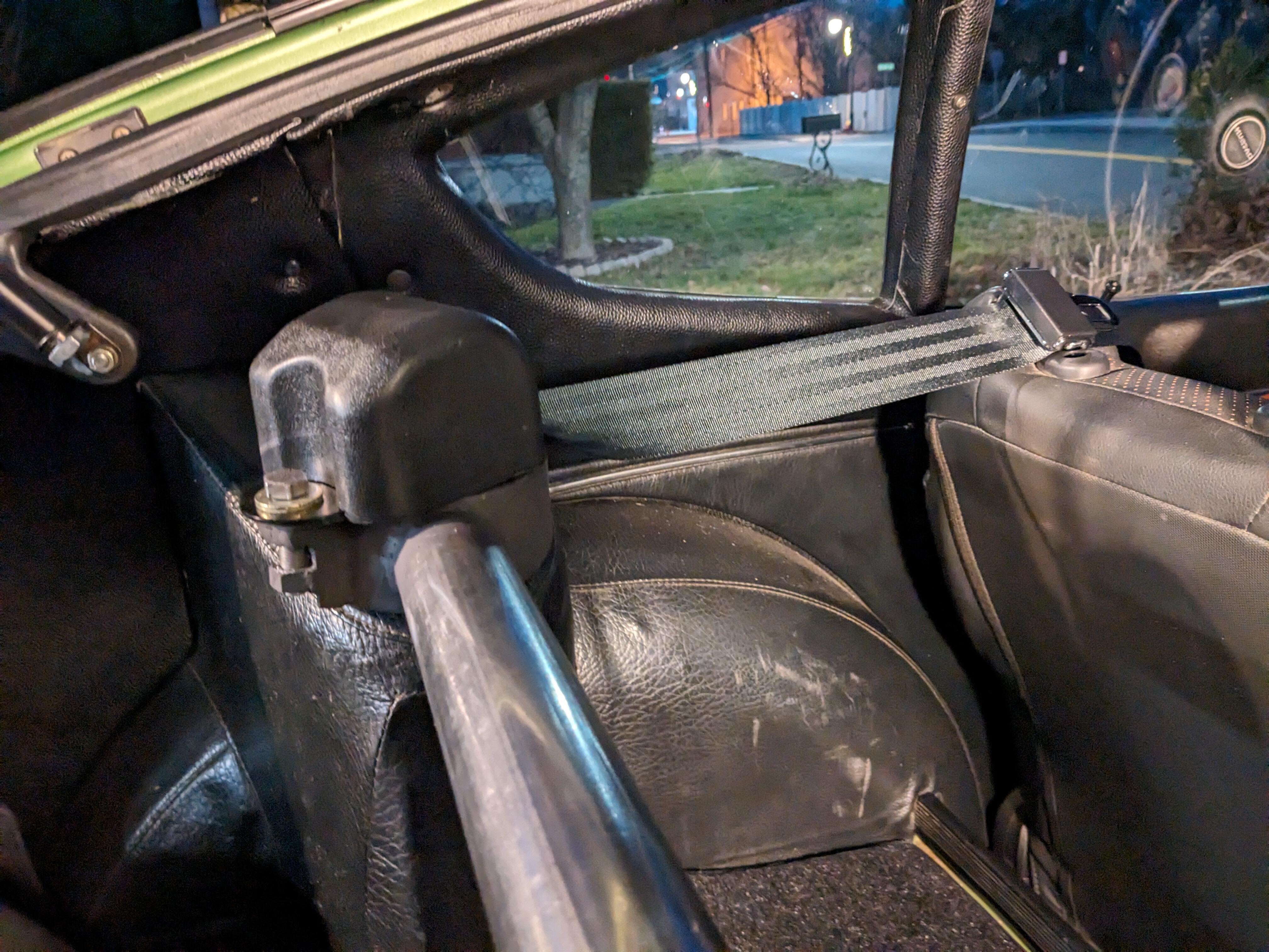
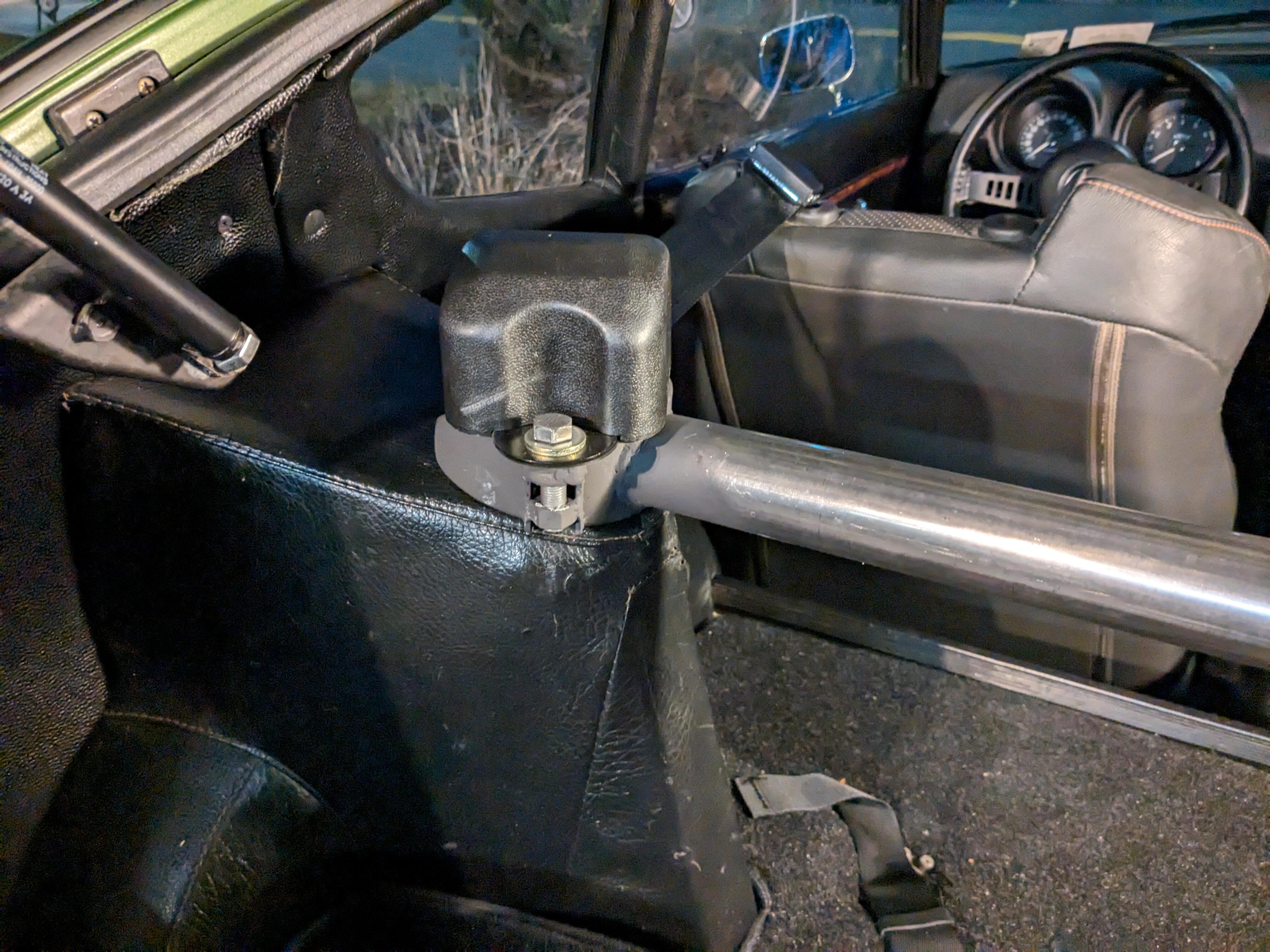
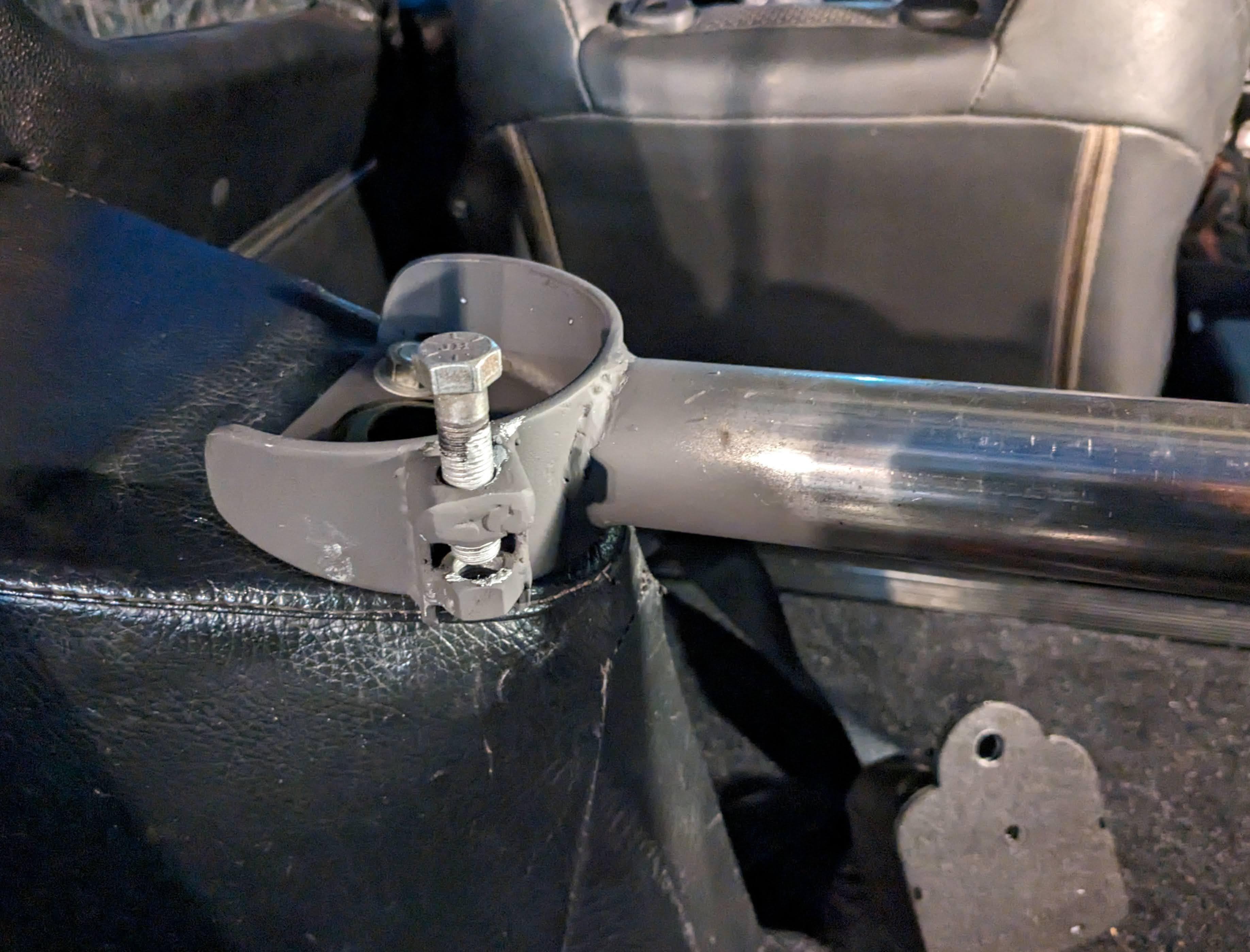
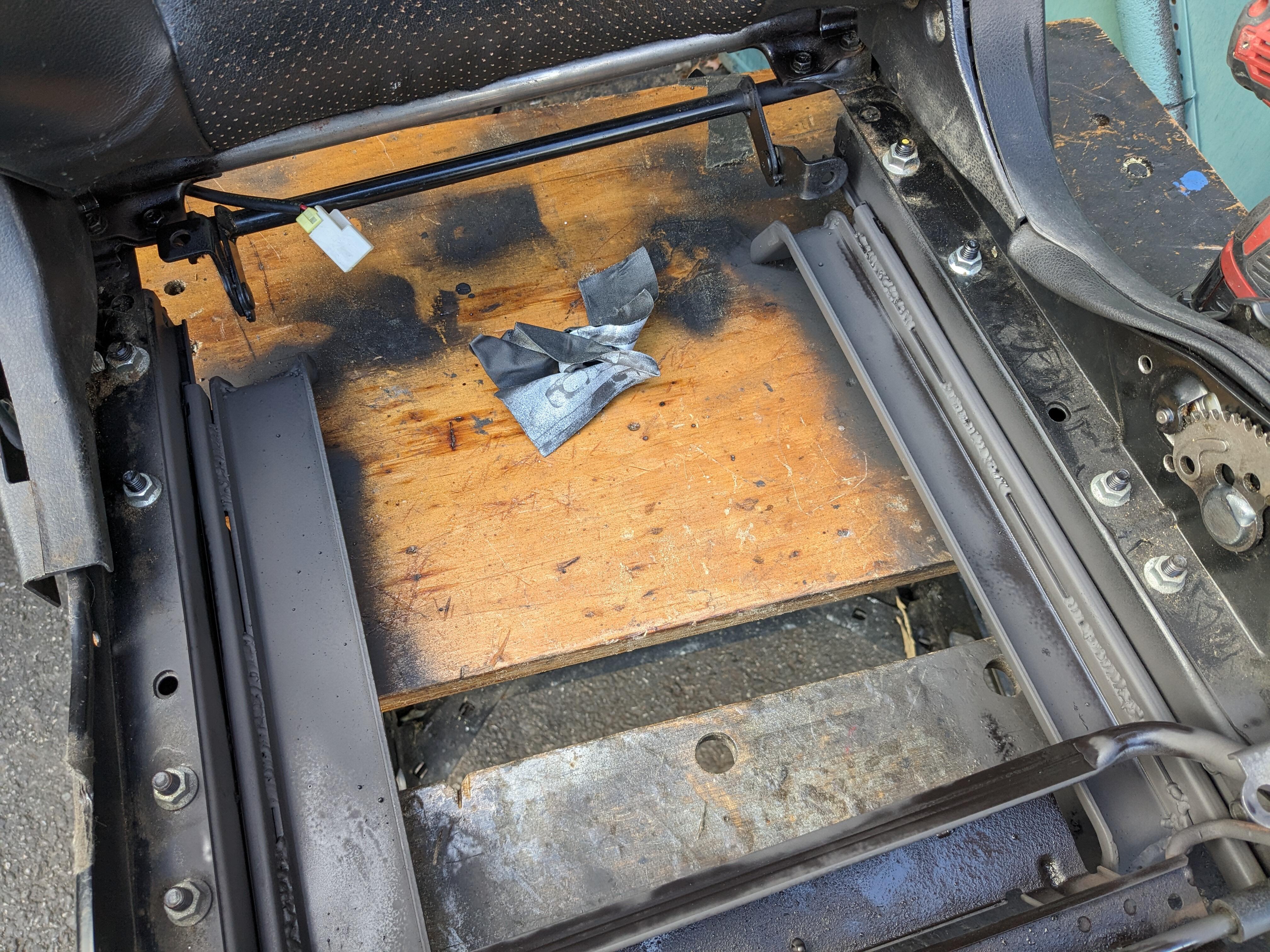
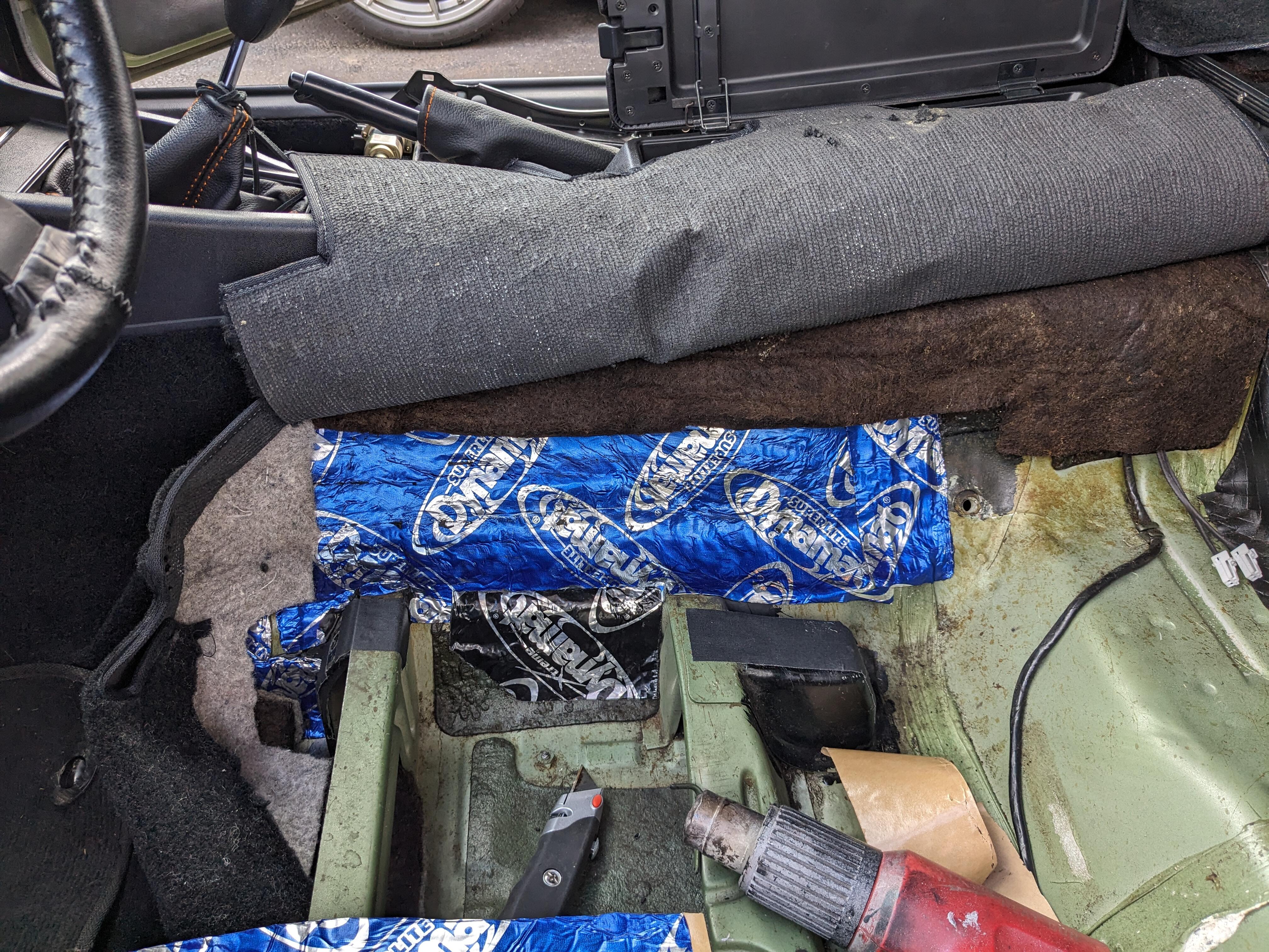
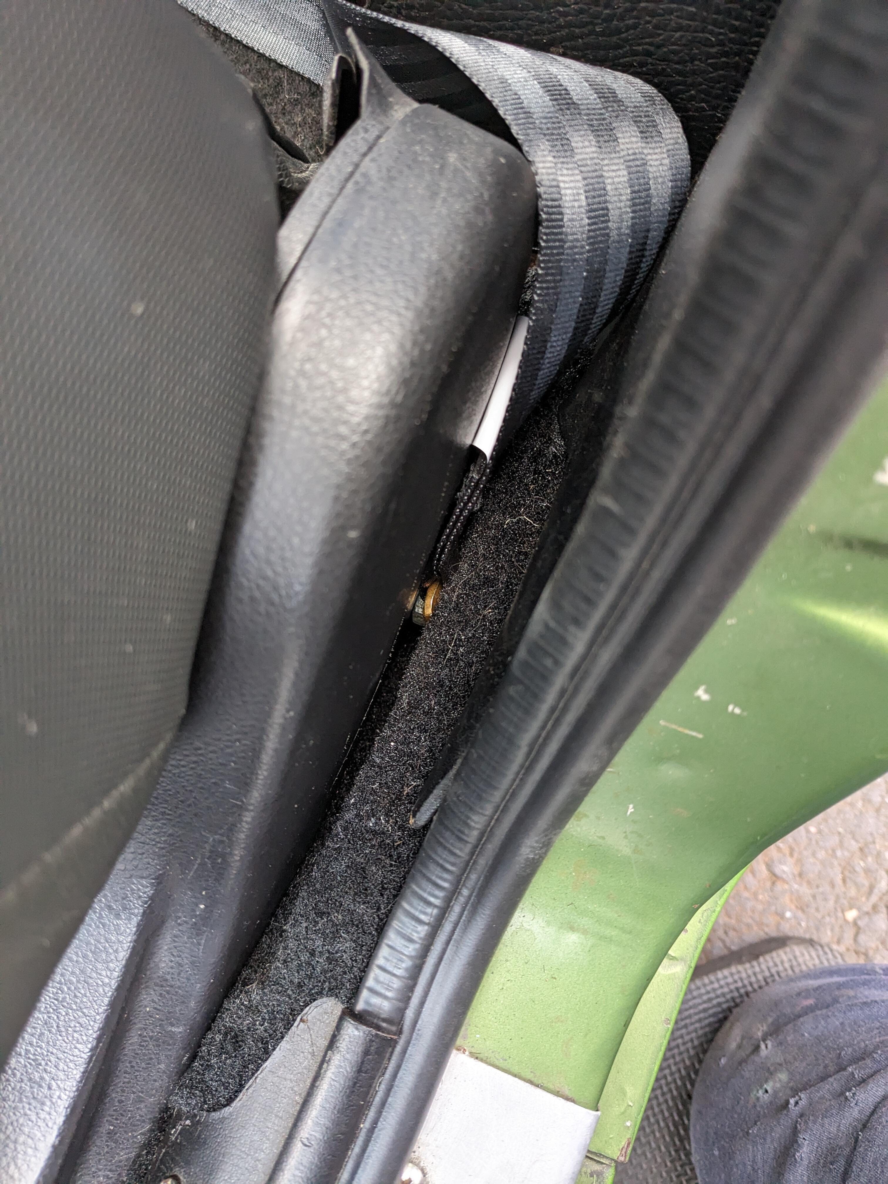
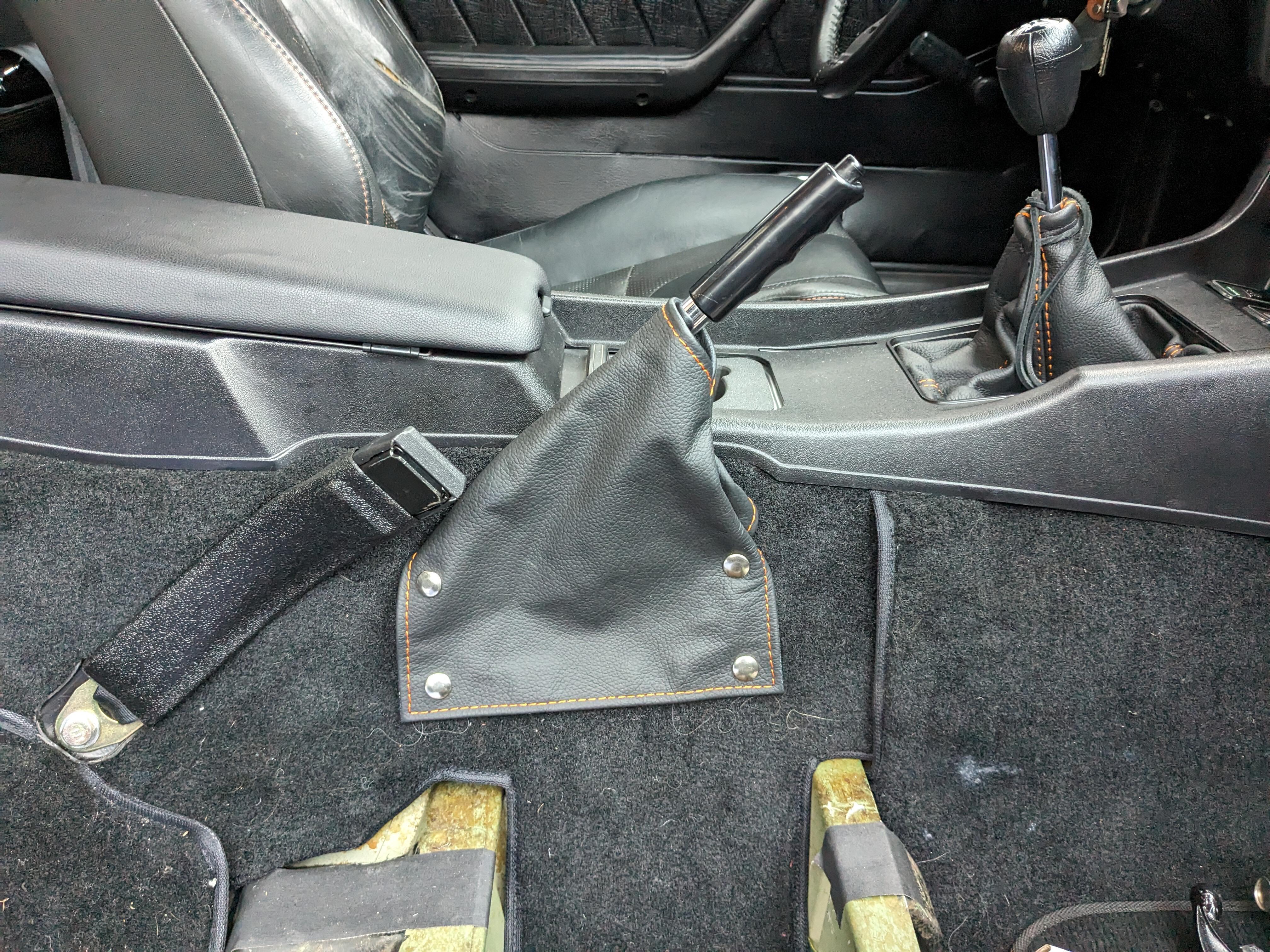
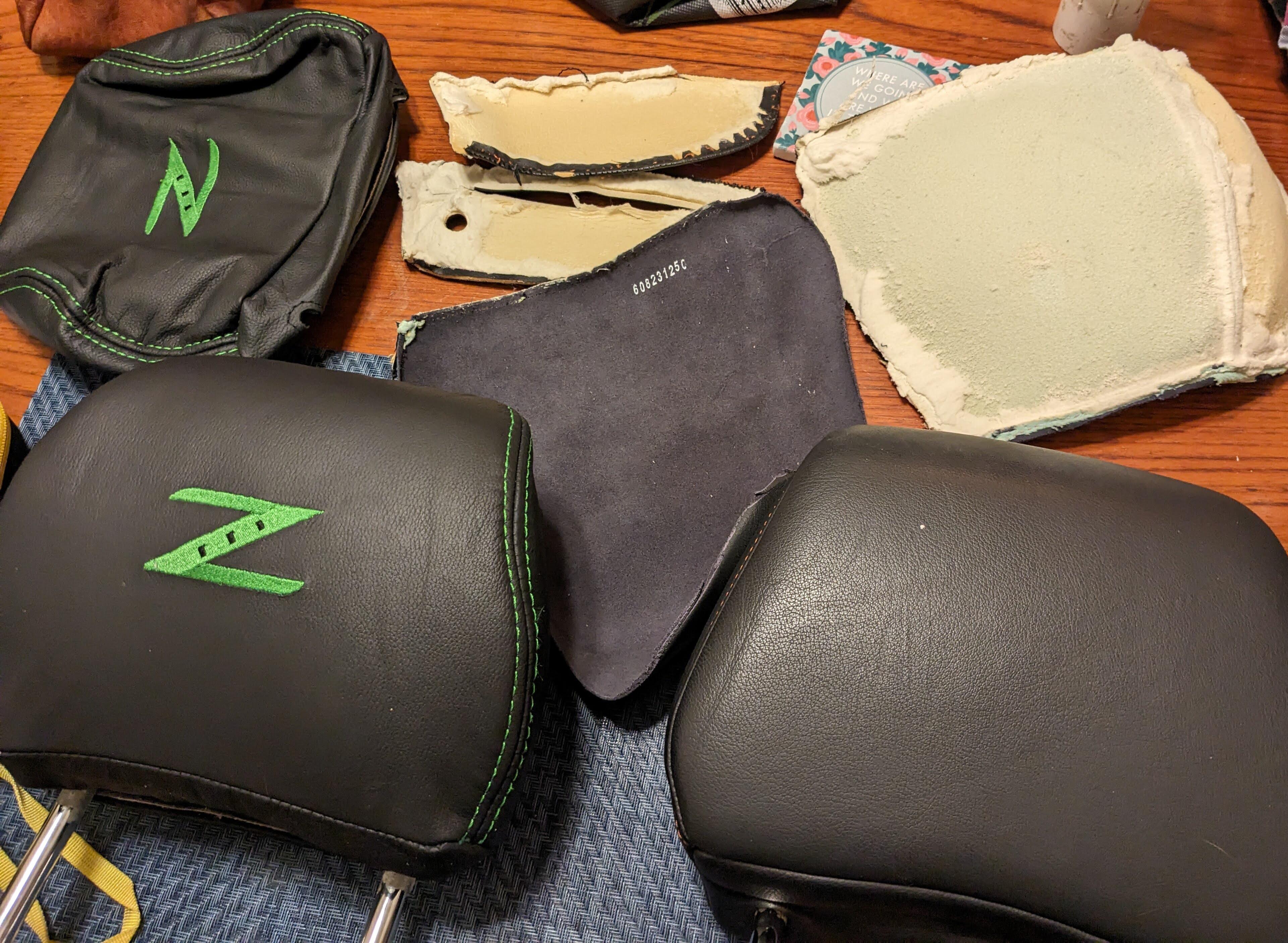
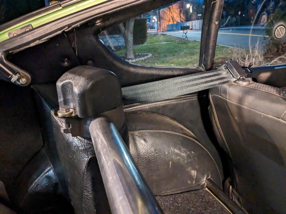
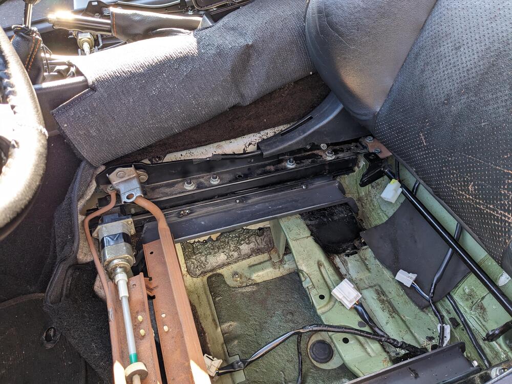
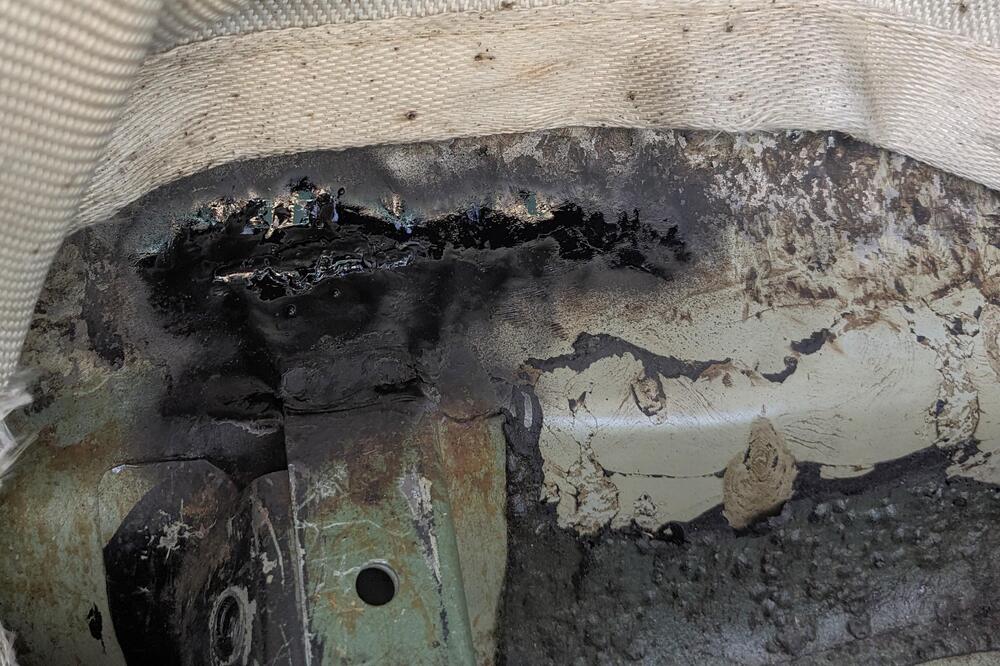
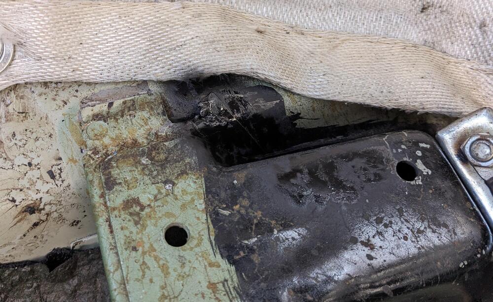
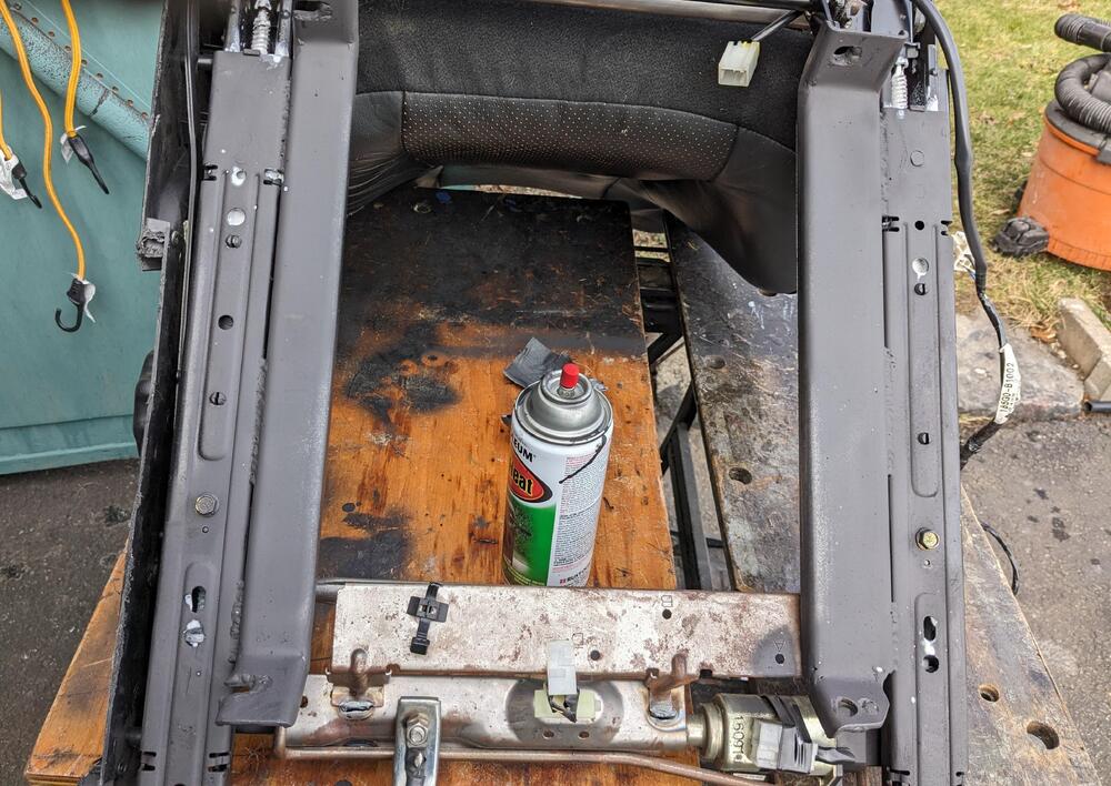
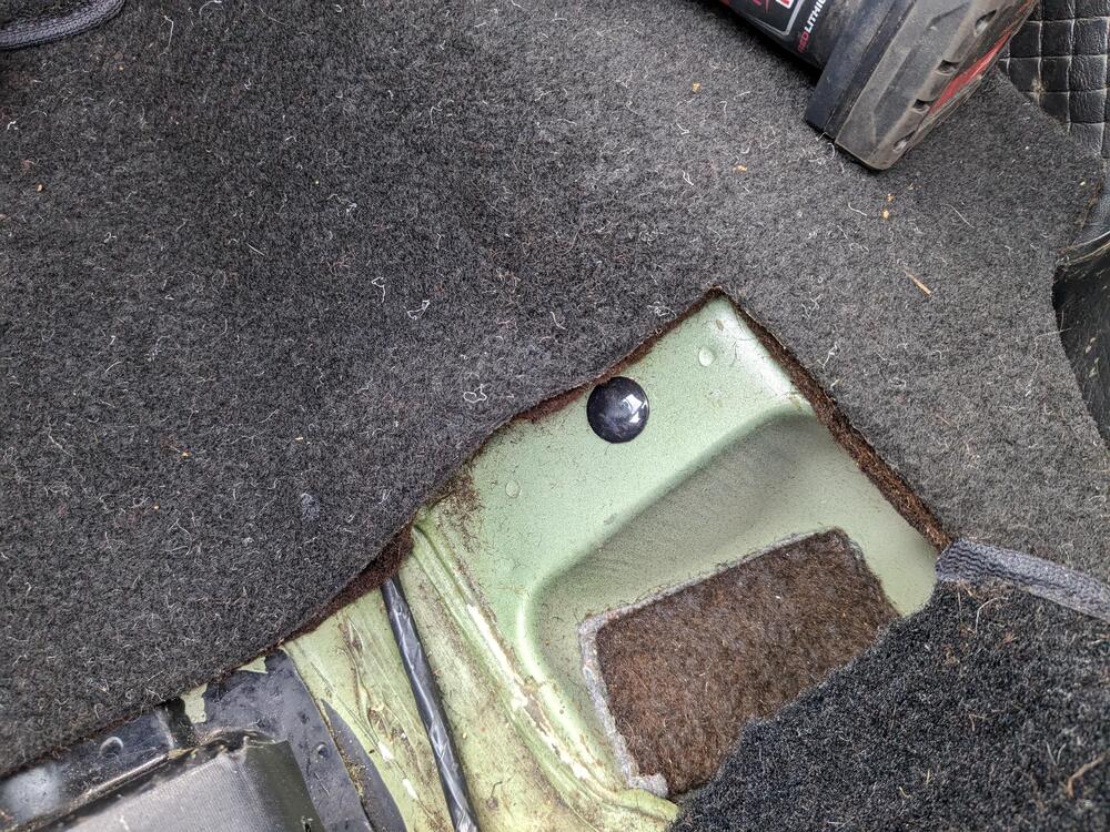
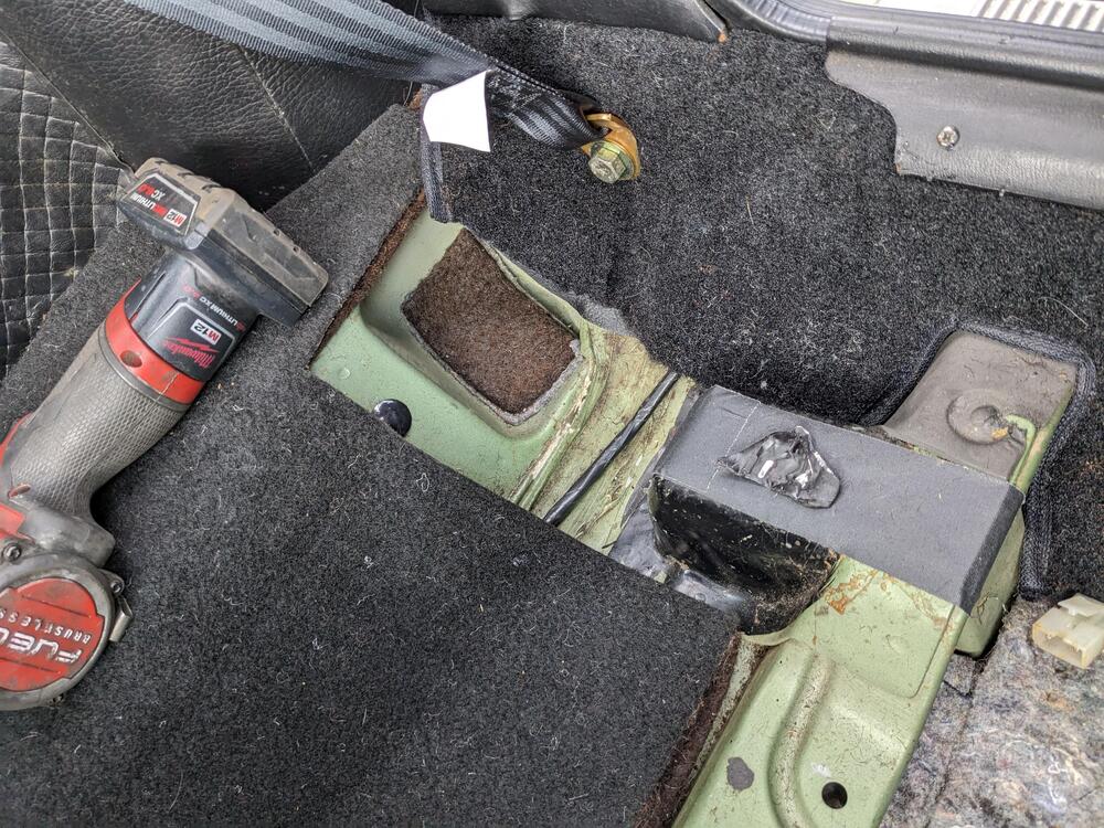
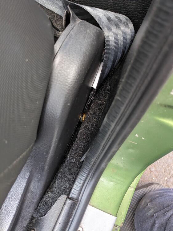
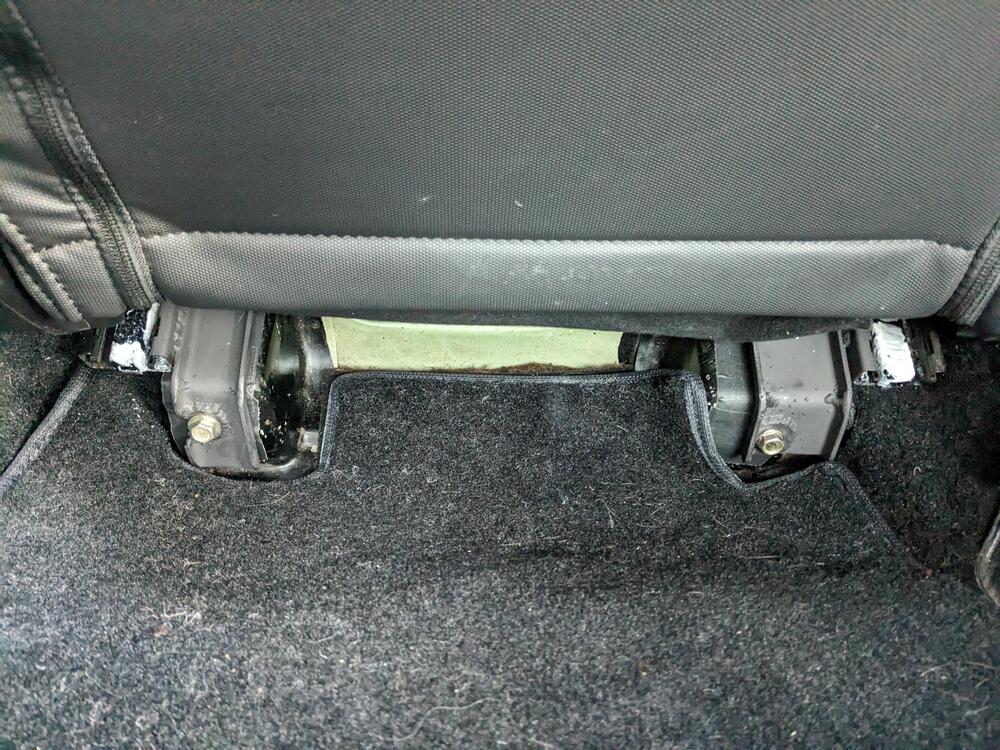
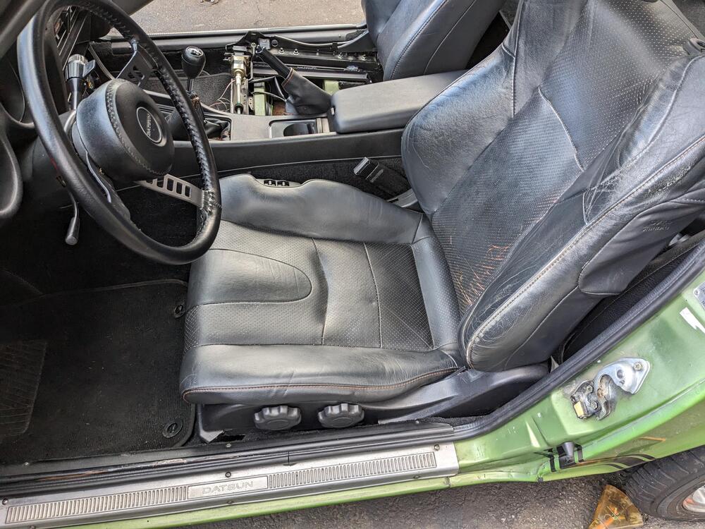
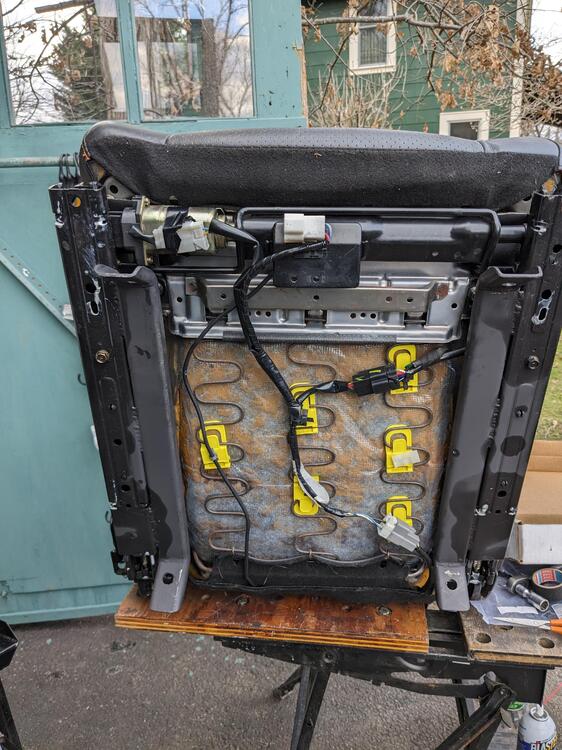
2 pointsGot back from Baltimore yesterday afternoon, so back on the seat install today. Had to do some more pounding on the tunnel. Metal only stretched so far, then it split, about 3" wide, a couple inches above the seat crossmember. flange tore where the black paint is on the tunnel. dynamat after paint after that, I welded the rail adaptors - tacked in place, then removed to stitch plug for stock seat belt bolt hole (Wesco) seat belt outer Wesco seat belt inner , also added receiver snaps in the carpet for the leather handbrake cover Driver's side, rear attachment sill spacing - just clears the seat belt Seat will be re-upholstered, just not today pass seat out to install cushion, harness routing Headrest cushions have to be stripped to fit the new leather covers, the original covers are glued to the foam


 2 points
 -
1 point@ckurtz2 the thread linked in the first post has some links to the bearings that were used.1 point
-
1 pointOK. I didn’t know that. You’re probably right about them then. Thanks!1 point
-
1 pointHey sorry, wasn't able to check everything till today. History of engine... Long story short the head was rebuilt between 500-1000 miles ago (sorry can't give exact number) after pistons met valves (timing sprocket came off while running) at a shop. Shop replaced pistons/ rebuilt head and replaced valves. Before this happened at the shop the head had been rebuilt already, new timing chain, tensioner, etc. Engine was completely refreshed but the block never taken apart if that makes sense. Oil pressure when cold sits around 65psi and when hot around 30-40psi. It is running a comp cam 260s / MSA 6-1 headers / aftermarket fuel rail. Everything else is pretty much stock. Compression 155psi across the board. In regards to the valve springs. Honestly, I have no idea if they were replaced or tested (I assume they are the stock ones). Cam wipe patterns look good on rocker and cam.1 point
-
1 point
-
It annoys me when people in my life say I should sale my Zs while the market's up like it is. They look at BAT and ebay then advise me about cars I know better than they know their kids.1 point
-
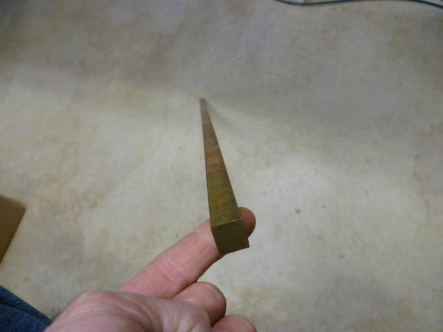
1 pointI know you already took care of your column without taking the bearings out, but just so they exist somewhere, here's my photos from the job. Note that if you are going to take the bearings out of the column, you'll obviously need to have the column out of the car and disassembled. Tap the bearings out of the housing if you dare. I used a long chunk of brass rod because that's what I had laying around and used that to tap the bearings out from the far end. The bearings are press fits into the column tube, but it's not a very tight press. Work your way around the perimeter tapping gently and you can walk them out. Here's the long brass rod that I used: Tapping around the perimeter, walk the bearings "gently" out of the tube: Then once you get the bearing assy out, you can pop the retaining ring and lose the balls: There are thirty balls in the bearings so you can count what you have to make sure you didn't drop any: I've been through this job a couple times now and I have added additional balls to the bearings. Not necessary, but I like the feel. I think it tightens things up a tiny bit. Originally there are thirty balls and I usually add one on each end. @Sean240Z added two balls to his and he really likes the way that turned out as well. So now that you're already done and the pictures were late to the party.... Let me know if there are any questions.


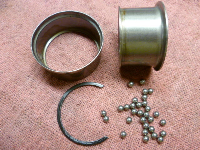
 1 point