Phred
Community Member
-
Joined
-
Last visited
Everything posted by Phred
-
:stupid: Sorry to rag on this, but your duration numbers are bogus. Also the 262/272 numbers are useless without reference to int. or exh. and at what lift were these numbers taken? Advertised, or actual timing figures? Different cam grinders will sometimes specify special lift numbers to degree a cam, and then advertise it with theoretical duration numbers. So, whenever you quote cam specs, be sure to get the whole story, or it just adds to the confusion. The only way to compare cams is to note the lift (usually .050) at which the duration points were taken. The theoretical, or complete duration looks good on paper, but is not usefull. Because of the lash used in a running engine, the duration numbers (the amount of time/distance measured in degrees) will not be representative of the advertised numbers unless the cam is degreed with the lash specified by the cam grinder. Yes, it can be confusing. Just be aware of the facts, and don't throw out numbers without all the specifics to back it up. Phred
-
Factory Service Manual Specs: 4.5 to 6.5 ft. lbs. I assemble these frequently and use a in. lb. torque wrench set at 72 in.lbs. Over torque can split the gasket at the bolt hole. Phred
-
I agree with Bambikiller. Also don't waste your money on the Nissan Comp. race damper. Its very expensive, and you dont need it unless its an all out race engine. The euro damper only has one integral pulley groove. If its a street car just a standard replacement damper will work fine. Since it came loose, the front seal may also need replacing. Check the threads closely on the attaching bolt, and replace it if damaged. Reassemble it with locktite and 95 ft./lbs. torque. Phred
-
You'r close Walter, L-28 cranks are from 46 to 48 lbs. Phred
-
Xtinc, The gap between the plunger and body of the tensioner on your engine is not unusual if it has had the deck surfaces machined. To determine how much the head has been cut is easy. A stock L-series head is 4.250 thick, ( from cyl. deck to cam deck.) You must use a digital caliper or micrometer to measure it, then you'll know how much its been cut. Its harder to measure the block height when its assembled, and I can't remember off the top of my head how tall the stock block is anyway. Be carefull when (if) installing cam tower shims on an engine which has a used cam and rockers in it. The cam/rocker contact patch will change, and will require different thickness lash pads to realign the contact area. If you have the same cam/rockers as were used prior to your rebuild, and they are both stock, I would run it as is. The only other very minor consequence will be a slight increase in the wear on the bottom of the tensioner rubber, as the chain won't run smoothly againt the face of the rubber for the first few hundred miles. This will not degrade performance or engine life. The only other problem I see from your picture is I don't see any washers under the heads of those bolts holding the tensioner or chain guides. Washers are important here, as they distribute the tporque load. Its not unusual to find broken chain guides in improperly assembled engines. Use a flat and a new lock washer on these parts, or just a flat washer with locktite and 7 ft. lbs. (or 84 in. lbs.) of torque.
-
halz, good point to consider! Some race shops will use a +/- .5 ( one half a cc) as a maximun deviation. Which means if all six chambers are within one cc, its good to go. This is usually acceptable, untill compression ratios start to get critical, (12:1 & up) and total compressed volume gets small. Then variance between chambers should be kept to +/- 2 or 3 tenths of a cc, Also, use the smallest chamber to compute compression ratio. It may be helpfull to try this formula for computing compression. Its quicker and less involved than others. First, compute displacement of one cylinder bore x bore x stroke x 16.387 x .7854 Then compute total compressed volume: vol. of one chamber + vol. of head gasket + vol. above piston at TDC ( example- a dished piston, or if a flat top piston is below the deck at TDC) To find compression ratio: Divide displacement by total volume and add (1) Phred
-
Attn. jmortensen, Your on the right track. A few little tricks will ease the effort required to cc your head. Install the spark plug with a little white grease on the threads, also dab a little of the same stuff on the valve seat area, and then drop the valve onto its seat. The white grease is easy to see and will seal the chamber, no spring is required to hold the valve down. Then seal the plate over the chamber with the same white grease, again because it is highly visible, and creates a good seal that won't wash away, but can be wipped off easily. Then, drill the hole in the plate offset so it is located at the edge of the chamber between the valves. Then set the head up on your bench at a slight angle so the hole is the highest point. Then when filling the chamber, the air will escape out the top leaving no bubbles to contend with. Finally, use cheap rubbing alcohol (99 cents a bottle) and add a little food coloring to aid visibility. The rubbing alcohol has low surface tension, and will flow more easily than other liquids. If you're really into this sort of fun, go down to your local pharmaceutical supply house and buy a cc burett. Zero to 100 cc's works best. I've been doing this for many years, and have found this to be a fairly cheap, painless way to get accurate readings. Phred
-
Cam, rockers, timimg gear, even valves, retainers, keepers, all that stuff I'll give you a few buck for if you can't get rid of it locally. Phred
-
Proper steps to timimg happiness. First verify TDC on the compression stroke. Pull # 1 spark plug out and stick your finger over the hole. With a remote start button or with a socket on the damper bolt, turn over the eng. till it blows your finger out of the hole. Now with a light to peek down the # 1 hole, and the wrench or socket on the damper bolt, turn the engine very slightly back and forth to visually confirm the piston is at TDC. If you have trouble seeing, stick a screwdriver in the sparkplug hole as verticly as you can and then again turn the engine by hand slightly back and forth and watch the screwdriver go up and down. After you think your as close as you can get to TDC, check the timimg marks. Put a small dab of white paint on the damper pulley where it aligns with the timing pointer. Now you have located TDC on the compression stroke, Probably within a few degrees if you have a good eye. Now hook everything up, set the timimg light to ten degrees and fire it up. Final note, do not exceed 36 degrees total advance. good luck. Phred
-
That type of screw extractor tends to expand the part your trying to get out, so don't crank on it too much or you will split the bolt. But, I think you're in luck. The pic shows you have about three threads above the deck. I have removed many broken bolts with this method. Get a nut with the same thread as the head bolt. tighten down the nut all the way to the deck. Weld the nut down through the center, to the remaining bolt with a TIG welder. Then simply remove the nut/broken stud with the proper size socket. The heat from the welding process will also tend to loosen the rust bond to the block. Good luck. Phred
-
Ed and 2Many are correct. Because of core shift in castings, one block may be able to go .120 oversize. While another block might hit air at .120. Its best to error on the safe side, and only go .040 over, especially on a turbo where pressure and heat are greater than a N.A. engine. I have used a sonic tester on blocks, and I can assure you that there are good blocks and bad blocks. Also since you are looking for a quality job here, specify that your block be honed with a deck plate, to be certain that the rings have a nice round bore to seal up to under that extra cyl. pressure. Phred
-
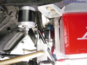 Is that a solid mount on the moustache bar? Did you build or buy the adj. sway bar? Looks too nice to drive. But not too nice to race! Phred
-
You get an "A" Mark. Fly cutting pistons gets its name from the type of tooling, or cutter used to mill reliefs in the tops of pistons. When aftermarket cams are used that have higher lift, and longer duration, they sometimes can come in contact with the pistons. This usually happens from ten degrees before, to ten degrees after TDC. Most race engine builders will temporarily install the pistons, then set the head on with no valves. Then with a long center punch made out of an old valve, drop it down through the valve guide to make a small mark on the piston top. Then with the pistons disassembled, and mounted in a special holding fixture, the cuts are made in the pistons, centered on the marks made with the punch. Then final checked again to assure that they have the required clearence. Safe clearence for valve to pistons is generally .060 for the intake and .090 for the exhaust. This operation is sometimes referred to as Bridgeport cutting for valve to piston clearence, because a universal head Bridgeport milling machine is commonly used. Phred
-
Ditto to what 2ManyZs said. I might add if you have any children you can sell, you can get more parts for your Z. Phred
-
Hi Tim, FWIW, I built a forged piston engine for street use, a few autox, and general driving. I started it out with .005 pist./wall clr. After 54K miles I took it apart mostly cause I just wanted to see how it was doing, and for a rebuild. Every thing was fine, so I honed it and put in a new set of rings. It then had about .0055 clr. I sold it so I don't know how long it lived after that. Iv'e heard some people say forged piston engines make a little more mechanical clatter till their warm, but I couldn't say that. Consider stock cast pistons have about .0015/.0025 clr depending on where you measure them, against .005/.0055 for a forged one. .003 difference, not much. I have never used any of the hyperutectic pistons. Phred
-
Also be aware that it is possible to have good compression and oilfouled plugs. The compression rings control compression and the oil ring controls the oil. so if you have a bad oil ring and good compression rings, it can smoke and look ugly, and still have good compression. Another possible culprit is a plugged breather system. Crankcase pressure would then seek the line of least resistance, that is, the weekest cyl. to vent into. But you will usually see leaking seals when this happens. An old engine builder once told me, The more you know doesn't make it any easier, just more confusing. Phred
-
Shot Peening - A Practical Guide For The Racer The principal function of peening is to increase the fatigue life of cyclically stressed parts. Small steel balls (shot) hammer the part, compacting the surface, which relieves both surface and granular stresses. The process builds a tough outer layer which is very resistant to fatigue cracking. This protective skin actually strengthens the part. The usefull life of a properly peened part is usually two to five times that of an untreated part. Shot peening is of most benefit on con rods and crankshafts. It can also be applied to almost any part subject to fatigue cracking. The following preparation is necessary before a part is peened. 1. The part should be Magnafluxed or Zyglo inspected. 2. All sharp corners, nicks, maching flash, and similar stress risers should be removed, smothed, and properly radiused. 3. Precision finished surfaces, such as pin bores or journals, require masking prior to peening. Intensity is the critical component in successful shot peening. High intensity peening will distort a thin section part. Peening intensity must be high enough to produce an effective skin, but not so great as to damage or distort the part. Controlling intensity in the peening process is accomplished by using shot of different density and diameter. It is also controlled by the distance from the gun nozzel, angle, air pressure, and exposure time. The intensity used for different parts also varies with the type of metal being peened. The ideal intensity for a specific part is determined by knowledge of metalergy, experimentation, and experience. Double Shot Peening: Most parts benefit from double shot peening, wherein the part is first peened using larger shot and high intensity. Then peened a second time using smaller shot, (usually fresh glass beads) and lower intensity. This produces a much improved surface appearance and considerably improves the fatigue life over single shot peening. Double shot peening is a patented process, U.S. Pat No. 3,073,022 issued to General Motors. The rights of which are not being enforced. I mention it only to underline the value of the process. The patent papers cover seven pages and include fatigue life charts showing life cycle comparisons between unpeened, single peened, and double peened parts. They leave no dought as to the advantages of double shot peening. Phred
-
I've tested a number of spark plugs on a back to back dyno comparison. I've done the tests on Datsun, Cosworth, and formula ford. None of the gimicky plugs produced more HP. The ones with special alloy electrodes last longer and handle high energy ignitions better. The only time I actually saw a HP difference was when we were able to change from a regular tip to an extended tip plug. This was because the regular gap plug was slightly shrouded. Plugs can have retracted, surface, regular, or extended gaps, or tips. The limitimg factor in the type of tip you can use is the physical clearance between the plug and valve or piston. L series engines without domed pistons will accept projected tip plugs. Also, make sure to use the proper length (3/4") plug. The most effecient plug will start the flame front as far inside the combustion chamber as possible. Finally, always use never-sieze lube on the threads, and torque 12 to15 ft.lbs. Phred
-
The wheels are the zero offset Z type. As I recall, I couldn't read any difference on the speedo. At the time, every thing else was stock. But I havn't driven it in almost two years now. And next time I do, It will be a Street legal Vintage Racecar. Phred
-
FWIW, This is what I had into my set. Which fit a 1 1/5" lowered 240 without problems. Local wheel supplier, (4) 16X7 Panasports $876.00 Tire America (4) 225/50ZR16 Comp TA R1 $560.00 " (4) Lifetime Computer spin balance $ 40.00 " (4) stubby chrome valve stems $ 12.00 " (16) Acorn lug nuts $ 16.00 Grand Total $1504.00 Phred
-
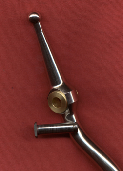
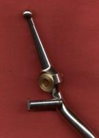
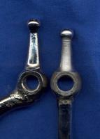
MSA shifter pic.
-
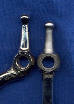
The MSA shifter is shown with some solid bushings I machined and installed to replace the stock ones. The other pic shows the difference between the early and late 5 speeds. the shifter with the re-welded, angled arm is from an early box. The straight shifter is out of an 80'ZX. Phred
-
ctomkins, It sounds like you learned the first rule of engine assembly. Don't take anything for granted, and always do a mock-up with new pistons to determine piston to head clearance. It sounds like everythings together, unfortunately. Hopefully, those aftermarket pistons are assembled with a full floating pin. Because if they are a pressed on piston/rod assembly, its going to be a headache to press them off, machine them, and then press them back together again. Many oportunities to screw something up. The Minimum piston to head clearance you should consider is about .045. With .050/.055 prefered (small safety margin) . Which means with a stock head gasket compressed thickness of about .047, your looking to have an assembled deck height of about -.005. Meaning the piston is below the deck by .005 at TDC. The next headache you may want to avoid, is called valve to piston clr. Hereafter called V/P clr. Let me know what cam you have, and if your pistons have valve reliefs cut in them. Also, if the pistons are still in the block, Get a very good dial indicator reading on #1 & #6 pistons at TDC. Take the measurement in line with the piston pin. Take notes, and mark the underside of the pistons with there respective cyl. #. (1,2,3,etc.) Use an electric pencil, scribe, or metal stamps. If you stamp #'s, put the # on the pin boss, & do not stamp in line with the pin. Give me some more details, and we'll get you squared away. Phred
-
Dev, Since your in for a complete rebuild, buy a workshop manual. Haynes has good pictures and procedures, and is priced right. I have the factory manual too, which is all inclusive but expensive. The Chilton has its good points, But the Haynes has better pictures, and like they say, worth a thousand words. These will explain all the stuff you'll need to know about replacing the chain and cam gear, which has three holes for timing. The Datsun crank is a real good piece right from the factory. Its forged, hard, and most are balanced very close. I have balanced many Z cranks, and they require very little work to get them spot on. There's no need to replace the rods. If you have the money, replace the rod bolts and nuts, and have the rods resized to .0018 min. to .0022 max clr. for the street. Again, if you have the budget, bal the rods. If you replace the pistons, go with .5mm (.020) overbore. Go with flat top stock pistons. All this applies to a street Z, and should be considered my (experienced) opinion. Phred
-
What kind of rebuild are you doing? The whole engine or just the head. As far as the oil press. goes, its not uncommon to see 15 lbs. at idle on an older eng. The things that affect the ability to produce oil pressure are the oil pump gear clearance, which increases with age and wear. This keeps it from pumping as hard as it did when it was new. The next thing that limits oil press. is the bearing clearance, which also increases with age. An increase in bearing clr. as small as .001/.002 can cause the oil to flow past the bearings more than desired, causing lower oil press. So if its an engine out rebuild, replace bearings, and oil pump. If this is a quicky rebuild, at least replace the oil pump with a turbo oil pump. There reasonably priced, and have slightly taller gears, for more volume. The pressure is controlled by the relief valve (springs) in the oil pump. The solid copper .031 ( stock .047 compressed) head gasket has nothing to do with the valve clearance. It will move the valves a little closer to the piston, but stock cams have a lot of valve to piston clearance. The increase in compresson from a .016 thinner hd. gasket will only be about .3 or .4 of a point. What will have to be considered is the cam timimg. An old timimg chain tends to stretch, Which will slightly retard the timimg. A thinner head gasket will have the same affect. So if you don't replace the chain, Reassemble it using the #2 hole on the cam gear. This will advance the cam timing by 4 degrees, making up the retarded condition caused by the thin gasket and old chain. One last caution. Many people have had problems making the solid copper gasket seal up. The stock composition gasket allows the slight movement between the head and block which occures because of the different expansion rates of aluminum and cast iron. So the surfaces of the head and block must be perfect (freshly surfaced) because the solid gasket will not mold itself to an irregular surface. Beware. Phred PS Oregon's so nice why'd you leave?