cgsheen1
Free Member
-
Joined
-
Last visited
Everything posted by cgsheen1
-
 No. The tach is connected indirectly.
 -
Couldn't help you with that, but I doubt either part would keep the tach from operating if it's wired properly (the tach and coil) . And if it's running - and running well - why would you think there might be an issue between the MSD coil and Pertronix module? The distributor module (Pertronix, points, 280ZX "matchbox", whatever) gathers info from the crankshaft and sends a "signal" for the coil to fire. It momentarily asserts a Ground on the coil "-" terminal. The rotor "distributes" the released coil energy to the various spark plugs at the appropriate time. If any of that isn't working properly there would be no well running engine.
-
You can download the Factory Service Manual for every year of Z car at nicoclub.com ( https://www.nicoclub.com/datsun-service-manuals ) Coil specs: Engine Electrical EE-26. Electrical Schematic: Body Electrical BE-5 I described the wiring for the tach operation above but: The coil gets battery voltage at Ignition ON through a Black/White wire. Black/White is a Nissan standard throughout the Z cars of the 70's for "battery voltage (or whatever the alternator delivers) when the ignition switch is in the ON position. NEVER assume a Black/White wire in a Datsun has anything to do with GROUND - IT DOESN'T! BUT - the 240Z Tach works on amp draw. SO, the tach needs the B/W that powers the coil to run through it (the tach) FIRST (before it feeds the coil). A ballast resistor was common for ALL single coil distributor engines of that era. Nissan designed the circuit so that power to the coil when through the BALLAST before the tach and coil. That's why the wiring is a bit confusing. IN THE STOCK CONFIGURATION, There are three (3) wires that make this happen: TWO Black/White (B/W) wires and ONE Green/White (G/W) wire that are in the harness bundle that pass in front of the radiator core support and then through a hole in the left side and end up in the coil area. (The coil and the ballast resistor are side-by-side) IF all three of those wires are temporarily disconnected. ONLY ONE of those two B/W wires will have power at IGN ON. Stock config: The B/W with battery voltage would attach to one side of the BALLAST. The Green/White (G/W) would attach to the OTHER SIDE of the BALLAST. The G/W returns to the TACH. From the Tach, the SECOND Black/White (B/W) RETURNS to the COIL "+" terminal. (IF you were eliminating the ballast for some reason, the B/W with power should attach to the G/W so it feeds the tach before sending power to the coil through the second B/W...) THUS: B/W from IGN Switch -> BALLAST -> G/W back to TACH -> B/W to "+" side of COIL...
-
Dang! Pictures of people in sweats! Down here we're still just sweating... 🤔
-
It sounds like the tach itself. From your description I would imagine there's a part inside that let the smoke out. I doubt the coil itself is going to have that effect. Perhaps removing the ballast had a role, perhaps not. Like Yarb said, maybe it's just old. There are discrete parts in there and perhaps the culprit could be found and replaced. The tach is just reporting entity and has no physical connection to the engine or coil. There is a battery positive and ground for power, but the "signal" is isolated - that wire is not physically attached to any part of the gauge. If you look at the back you'll see the G/W feeds a looped wire that goes through the same sort of device that a "clamp meter" (ammeter, amp probe, or the clamp that goes over the spark plug wire on a new-fangled timing light) has.
-
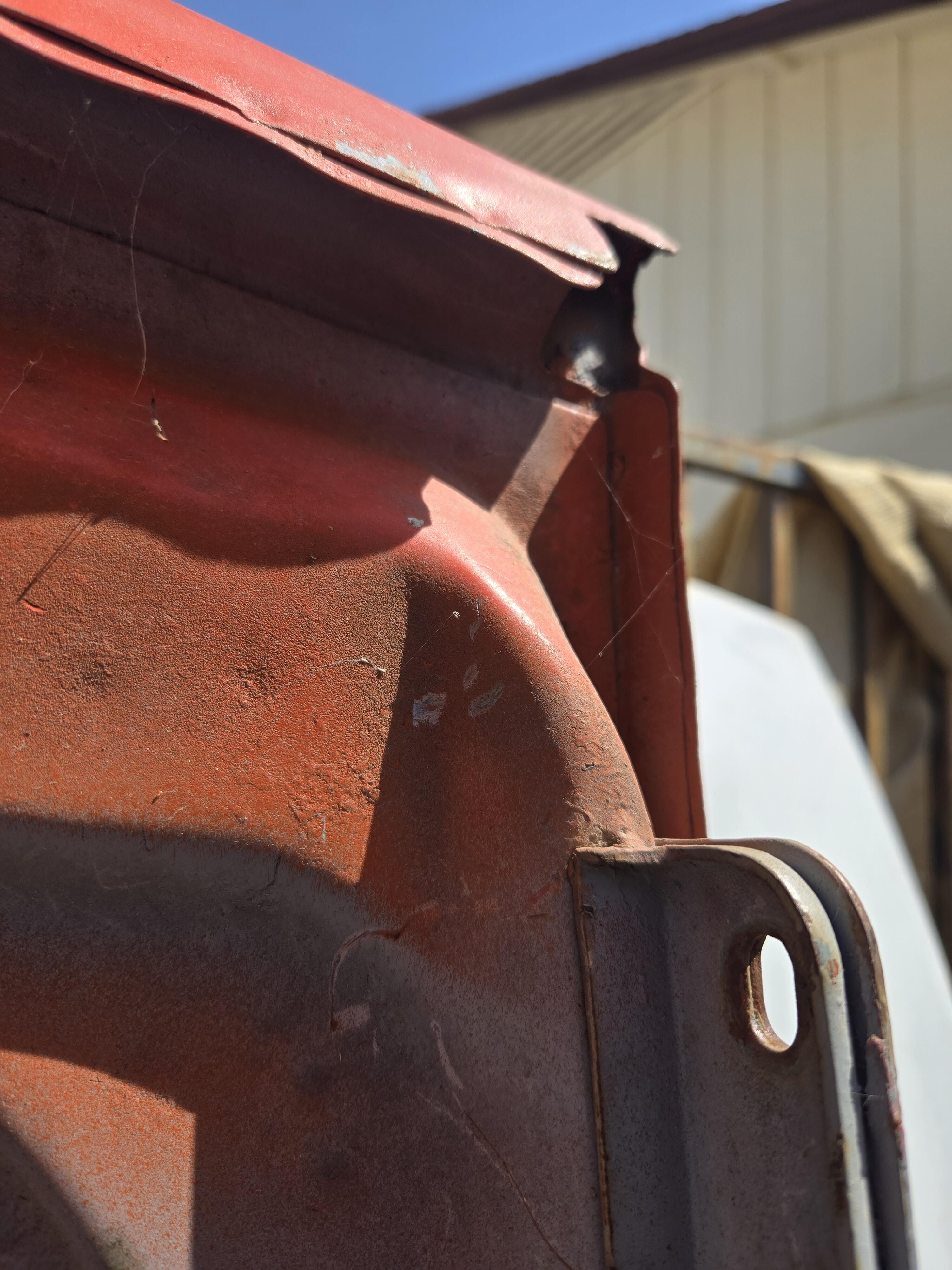
I can see from your pic the fun that the body man is gonna have with the lower fender and rocker and/or dogleg... Completely typical though.
-
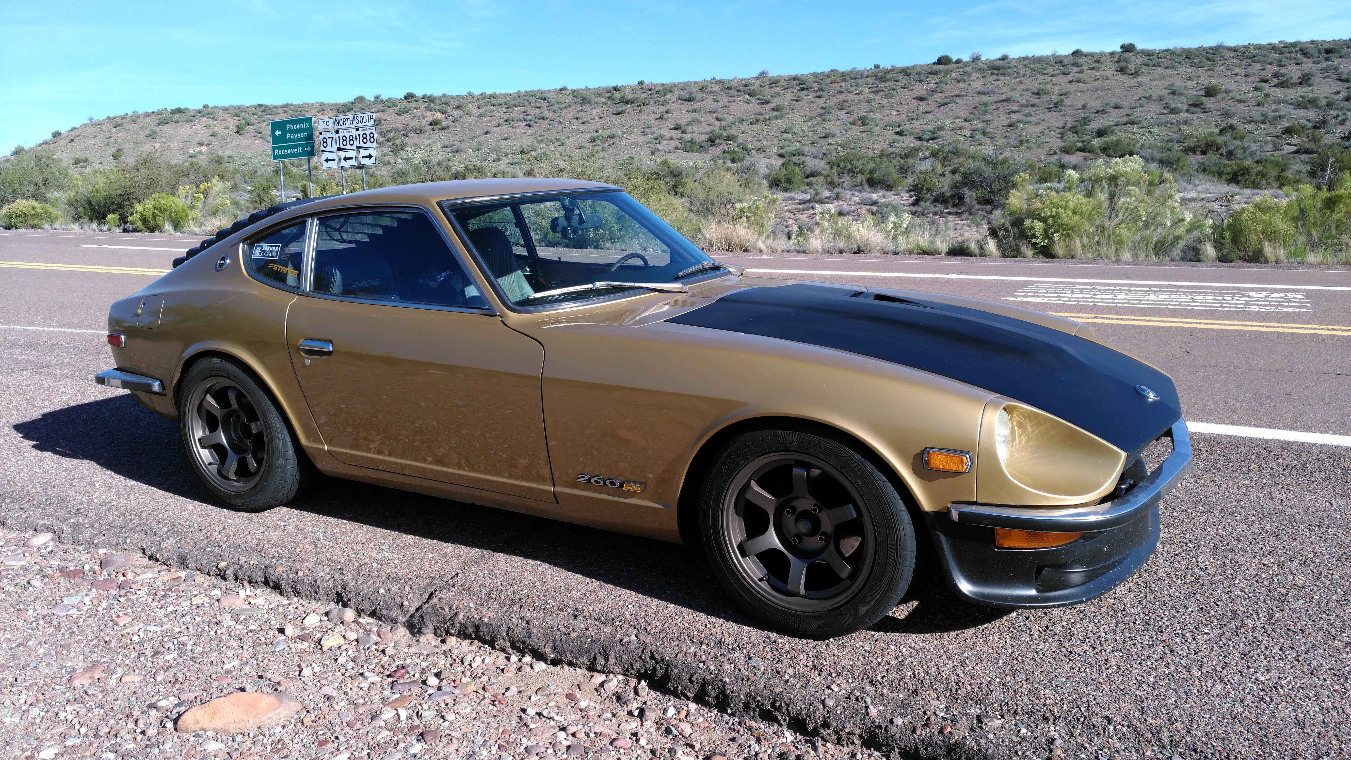
Very nice. (I'm also happy that you don't have any body side molding...) Could be just camera, but if you look at the two pictures of silver Z's you'll notice the slight difference in "tone". Not to fault anyone or anything. Two different painters can use silver metallic from the exact same can, and spray two slightly but noticeably different "colors". With silver, the flake is usually the majority of the color, and how the flake settles on the part will make a difference. As will the amount of material applied and the primer or sealer used underneath.
-
Not without knowing how your mechanic rewired your Z. Post pictures of the coil and ballast resistor wiring and the wiring coming back through the radiator core support to the coil and ballast. Although not uncommon at the time, Nissan used a Tach and wiring method not used in the later Z's - only the 240's. To make the Tach operate, the wiring starts at the ignition switch and winds all the way to the ballast resistor (a Black/White wire). From there they use a Green/White wire to go BACK to the tachometer, through a loop (stupidly simplistic explanation), and then BACK to the "+" side of the coil with ANOTHER Black/White wire. IF your mechanic omitted any of that, changed any of that, your tachometer will definitely NOT work... Your tachometer "reads" the amount of electrical current going to the coil to operate and in it's stock configuration it needed to go through the ballast before going to the tachometer and before finally powering the coil... If he just powered the coil, tach is dead. (Three wires here in stock config: 2 B/W, 1 G/W. If all are disconnected, the one B/W that has Battery Voltage when the ignition switch is in the ON position is initially attached to one side of the ballast resistor, the G/W is attached to the other side of the ballast resistor. That wire returns to the tach. From the tach the SECOND B/W wire goes to the "+" coil terminal. You can attach that FIRST B/W to the "+" coil terminal and the engine will run, but you've then bypassed the wiring to the tachometer.)
-
Silver is tough paint to spray evenly - even tougher to match ("even tougher" I said... nearly impossible). You want someone with a good deal of experience spraying silver metallic and that's not generally cheap. We always had very good luck with our supplier (Sherman Williams Automotive) and Datsun colors - what they had was very close to factory. I think we shot three silver Z's. Datsun metallic base paint is fairly inexpensive (for paint) and fairly consistent in price. It's the clear and hardener that will have a great deal of price variation. Be forewarned that cheap clear usually means greater LABOR cost or settling for a poorer outcome. Each painter you talk to will have a preference for the clear they use and they will have a reason they do so. If you go against their preference don't be surprised by additional labor or cost to get the clear looking the way you want it to. And please don't argue with the guy - after he's sprayed the paint you told him to. (Here in Phoenix our cost of just the final materials (sealer, base coat, clearcoat) of the brands we prefer would be just over $1,000 (using a very good clear but by no means the most expensive) and not talking of labor, fillers, or primers. We got a pretty good discount - and a painters discount may or may not be passed on to you. Paint cost is the very cheapest part of the job.) If you want the silver "to pop", spray dark sealer under the base. If you use a lighter sealer the silver metallic will look "washed out" and will not have as much character, For the most part paint IS NOT opaque. Underlying colors will have a visual effect - subtle but definitely noticeable. I personally despise masking around weather strip and trim. It may look acceptable at first but will eventually present a myriad of issues. Early on, we did one at a customers request and immediately afterwards made it a policy to NEVER do it again. You think you may be saving on labor cost to mask rather than remove but in reality labor saving is minute and the result is poor. We had several Z's come to the shop years after a "masked trim and weather strip" spray looking needlessly shabby. Pull the windows and trim and get paint underneath all the gaskets, trim, and weather strip. My last piece of advice - if you can't afford what the experienced painter quotes you just don't do it - don't look for a cheap quote. And, with a Z, you CANNOT hold him to an initial ESTIMATE (unless he doubles up). There are WAY to many unseen things that may pop up. (I said "MAY pop up"... Sigh... I can't remember a single Z in our shop that didn't have surprises unknown to the owner AND to us!) Oh,, ya,, we shot that. VVV
-
In our experience it was generally bearings - mainly the one under the reverse idler - and not usually gears or baulk rings - except maybe the reverse idler. Many of the same bearings were used in the "B" transmissions. If you replace baulk rings (which I would avoid unless there's obvious damage to them), lap them to make sure they move freely when cold... Ask me how I know (and how cold does it get in Arizona?).
-
How is that any more than just a guess - like the "I'm turning down the knob 2 1/16 turns"? Don't you need to know the AFR created by adjusting the jet position? And isn't the position different for varying temperatures and elevations?
-
Every single one...
-
Could well be -> intercooler, -> condenser, -> Koyo radiator (stacked up before the) -> fan. (unfortunately don't have a shroud - wish I did) Plus Phoenix softens up a lot of plastic at times (then dries it out, bakes, and cracks it). And I believe the blade length played a part in my particular case. Oh, and engine tilt vs. radiator non-tilt...
-
Okay, this is weird, but I'll mention it anyway. I bought a new fan blade (just like that) from Nissan and it was great - OR would have been if I had a stock radiator maybe. But I installed a Koyo 240Z radiator in my early 260. The Koyo is probably a bit thicker than stock - although there looked like plenty of room between fan and radiator. I drove my new setup a bit and pulled back into the shop. The radiator was leaking coolant. It had been hit from behind. I couldn't figure it out. (I first thought it was a defect I didn't see) The new fan had blades just a smidge longer than the old, hard blade I had been using. And they were nice and fresh and supple (well, much more so than my old crusty fan). What I EVENTUALLY found after I almost ruined a SECOND Koyo radiator: The stinking longer, more flexible blades of the new fan were flexing FORWARD ENOUGH for the tips to reach the radiator. Fast spinning nylon beats aluminum tubes and fins. (Koyo is side tank and the fan didn't hit the center, it hit the inside of the right-side tank and the tip of the blade was then pushed into the tube and fins on that side only - right next to the tank) Check the forward motion of the fan blades at speed. (having said that, I've found NO BETTER radiator than the Koyo for my Phoenix, AZ, daily driven, A/C pumping, turbo swapped, intercooled early 260Z - and I'm still using that old, hard fan... The new one is sitting on the shelf.)
-
I'd be surprised if you couldn't still get one from Nissan but my local O'Reilly's can get an aftermarket one in store in an hour for a stock transmission. (also, if you dig away the black goo that the two wires come out of on the original switch, you'll find a couple of brass solder tabs in there that what's left of the wire will still be soldered to. a bit of wire and a male and female bullet connector (with insulators)... Fill the cavity back up with silly cone - just sayin')
-
hmm, the cars are bad either...
-
They corrected that mistake with the 260's on - by putting struts on both sides. Not only does a single strut cause the hatch to twist but when closed there's always pressure on one side and not the other. The gas strut is constantly exerting pressure forward on the left hinge and not on the right hinge. You probably won't like the cure as it involves finding a parts Z - 260 or 280 - and removing the mount from the right side strut that's welded on there and moving it to your car so you can add a right side hatch strut. And I don't remember if the early Z hatches have captive nuts for strut mount on both sides or not. We had a guy in Scottsdale rebuilding a 240Z that wanted to add that second strut before he painted so we cut that bracket off a parts car for him. I've never tried to replace the hatch hinge pins (which might get worn). We learned early on to leave the hinges in place whenever possible as they're such a PITA to properly adjust once you've loosened or removed them.
-
Yup. Most of the pertinent info on Hybrid will be from 10-15 years ago. And probably most of the picture links won't be there anymore. I used to post a lot there but haven't been on in years... A 225mm flywheel and clutch package won't hold the torque of a turbo engine. I originally used the 260Z stock clutch and transmission (and R180) and realized after one drive the clutch wasn't going to do it - and that was at factory boost. I've been using an Exidy 240mm clutch and flywheel package for 12 years or more (well, 2009... How many is that?). I've been running 10-12 pounds of boost for quite some time. (You control boost with your RIGHT FOOT and even when you're driving hard, you're not always at full boost. Most of your driving time time is not in boost at all and if you're sized and tuned correctly, you're in and out of boost fluidly - turbo lag becomes a myth) If you're going turbo DO NOT go with a LIGHTENED flywheel! You need the spinning mass IMO.
-
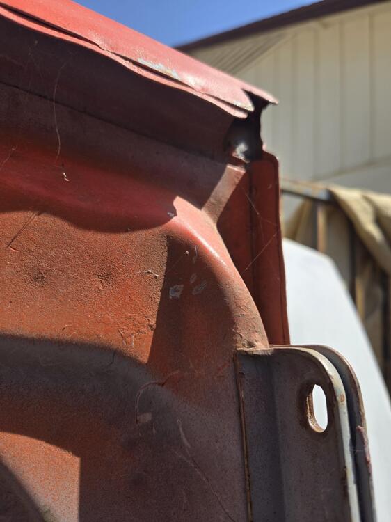
This one is close to real.
-
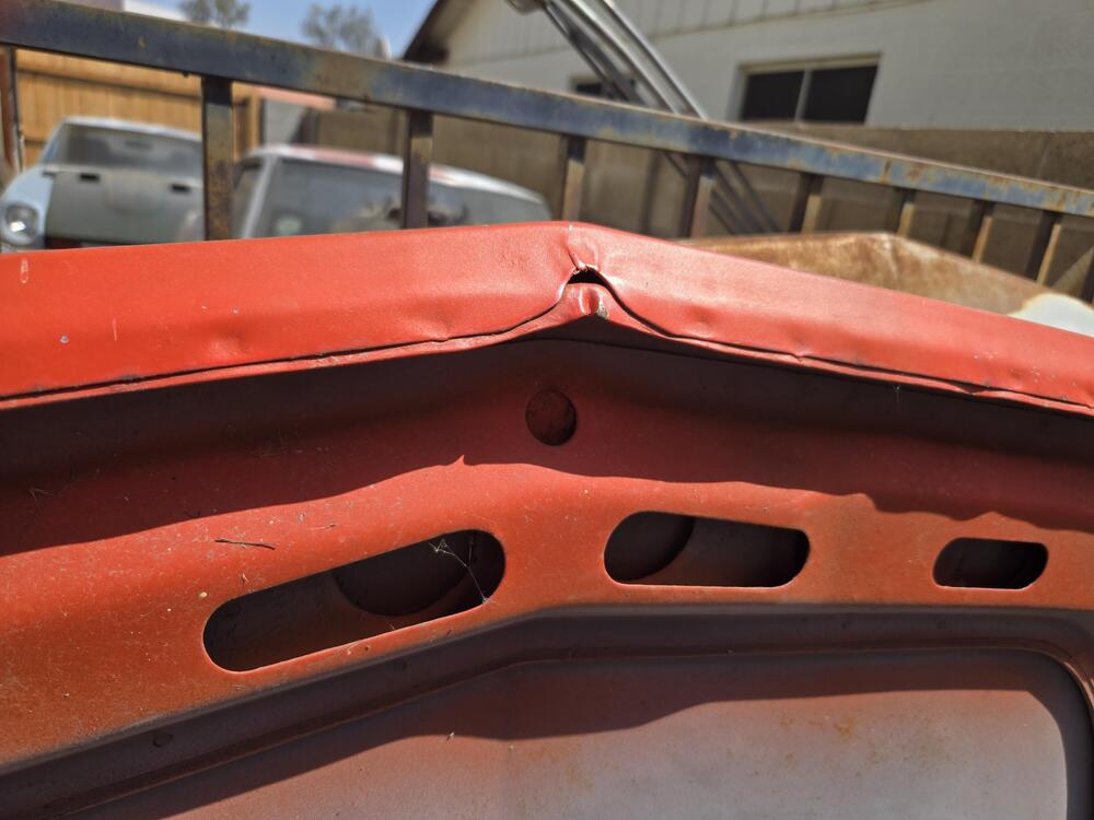
Uncrunched hood: Good point on the tip, correctly wrinkled steel, spot welds visable. (factory paint on this one)
-
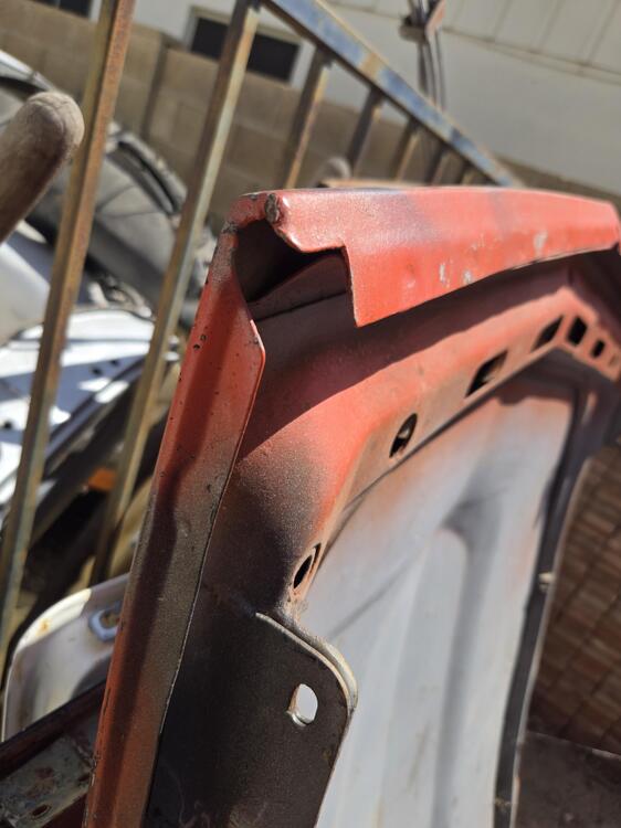
Sorry. This is a NOPE. Point of hood is wrong, no spot welds noticeable, way too smooth - it's been filled...
-
-
I had something similar on my L28ET that turned out to be a cracked solder joint on a connector pin. It drove me crazy for months, very random. Much like yours sometimes it would restart right away, sometimes take a few to several minutes to restart, didn't seem to be temperature related. Mine was not on the ECU but on the CAS optical unit in the distributor so that the ECU wouldn't always get the proper timing signal. You might look at the distributor (cracked magnet?) or the Electronic Ignition unit, or maybe the ECU connector solder to the board, maybe the EFI Relay or power to the ECU.
-
Be patient. Space heater to warm the whole thing up? (Here, this time of year, we wouldn't be having that problem...) I wouldn't use pliers. I'd try prying the end of the filler hose away from the tank (or the tank away from the filler hose - which ever way you want to look at it.) with one or two long prying tools (whatever works to catch the edge of the hose without harm - thin or wide) Long screwdrivers? Flat pry bar? Regular pry bar? Non-metallic pry tool? But you do need to somehow break the "bond" that the rubber has made with the steel inlet tube. Then treat the filler hose with Meguiar's Hyper Dressing...
-
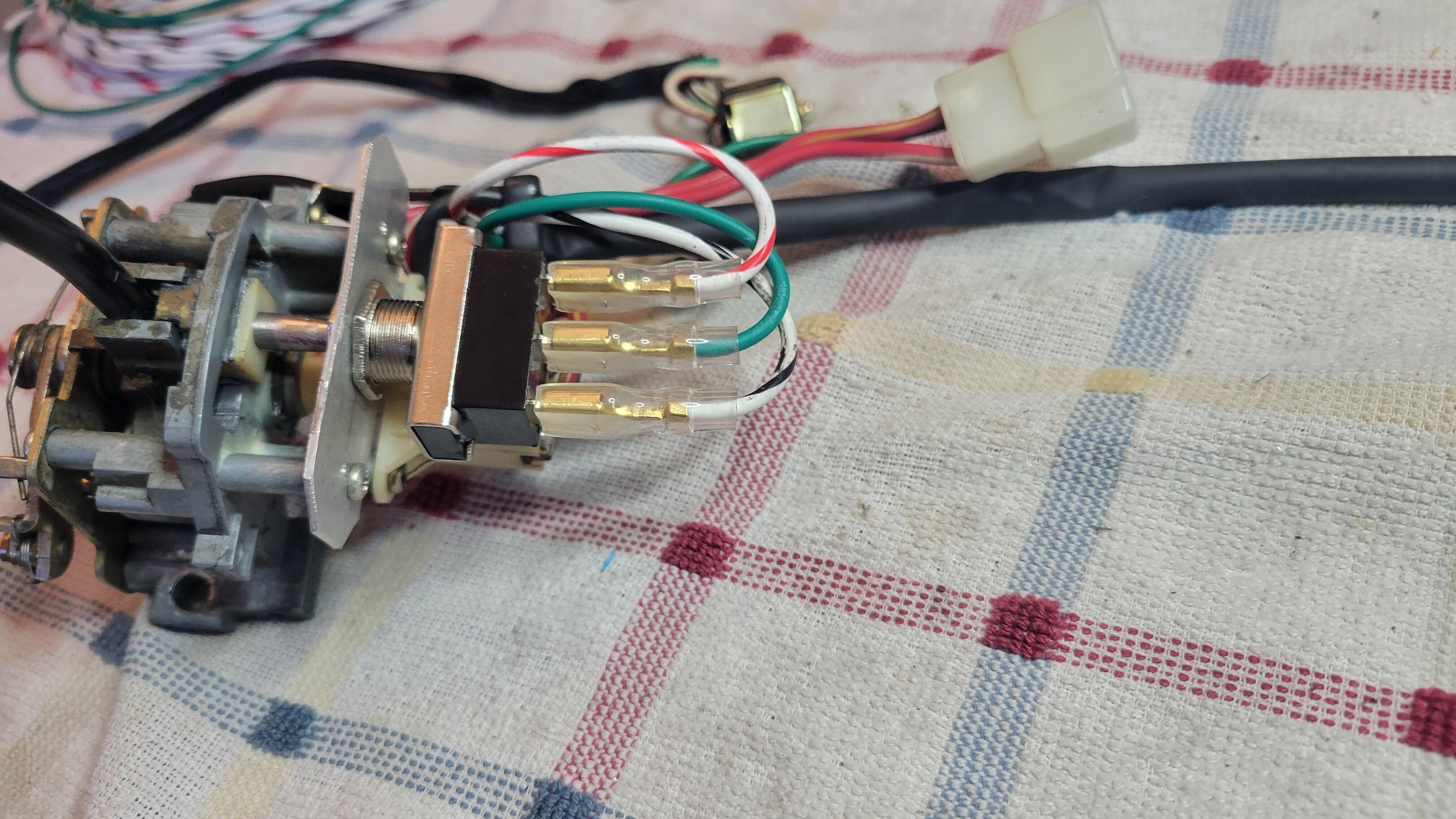
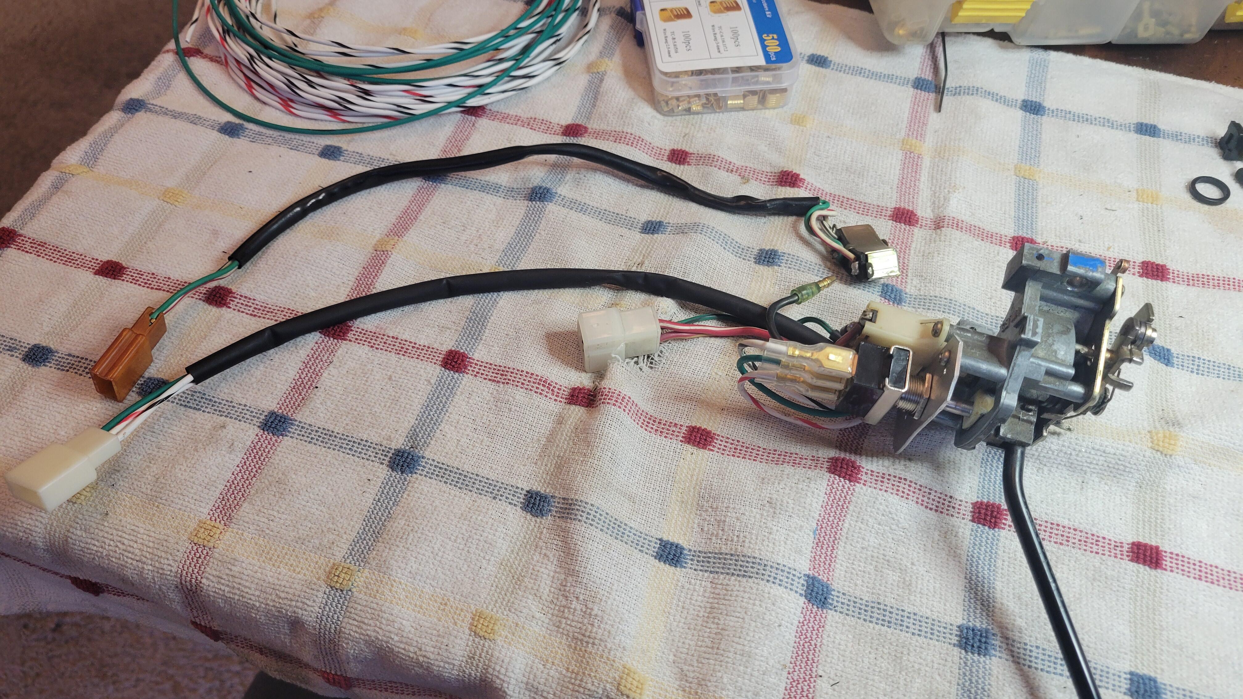
Found a picture that I took in the "let's see if that would really work" phase. In this picture the "mounting plate" (thin piece of flat aluminum) wasn't trimmed such that it would fit the clamshell. That took a bit of further modification to the shape of that plate. But it did prove that the toggle switch would be actuated by the stock turn signal components. I do not have dimensions without disassembling it. I also think it required a bit of trim on the switch handle for the end of it to fit properly in the "plastic thingy" of the turn signal assembly. (plastic thingy - which happens to be on thingaverse as a 3d printable item...) I got this metal toggle at O'Reilly but they can be had everywhere. You can see that the stock switch is much more compact and a little searching might find a smaller toggle than this one - and possibly with less protrusive electrical connectors... I wanted something simple and common.