zKars
Supporting Member
-
Joined
-
Last visited
Everything posted by zKars
-
I does not store maps within the App, you only have the "Current" map. You can edit the map interactively then store it in the distributor. The map can not be altered when the car is running, EXCEPT for a blanket + or - advance adjustment of the current map in use.
-
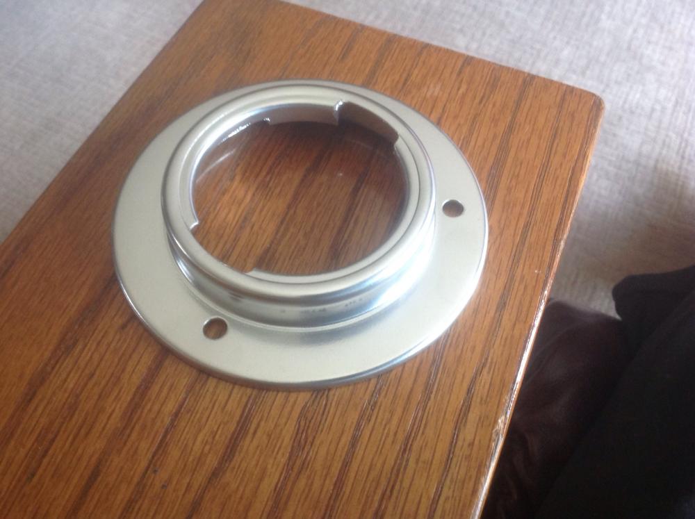
Here is a modded ring with Eastwood's "Reflective Chrome" powder coat. It's pretty darn shiny! If I spent more time pre-buffing the raw metal, this would be darn purdy! This was done with just sand blast then medium wire wheel buff. Goes real nice with the chrome locking cap!

-
Charles that's great idea. Thanks for the free plating offer. Do you have a way to weld that bead before you do the plating? Doesn't make $$ sense for me to ship to you then you to her. Maybe just get Jai's and do the mod for her.. You two are on the same side of the continent!. In the meantime Jai can order up a cap then by the time you're done, she'll have all the pieces. I'll send my modded one to you first if that seems to make sense.
-
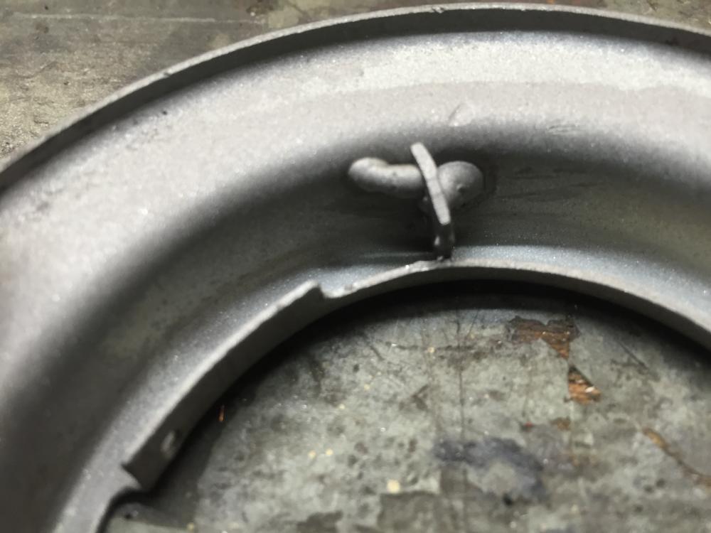
I have a simplified solution now. No more extra piece of steel to weld in, just a weld bead on the side that sticks out just the right amount. Also discovered that a stock cap's tangs wouldn't clear the initial extra bit, but the weld bead works just fine with either.
-
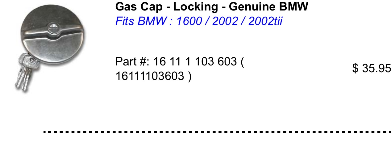
I suppose you all would go gaga if I welded a tiny bracket with a hole on the back of the BMW gas cap to provide a connection for that all-important chain, wouldn't ya? Plainly I need to sell a package of modified locking gas cap, and modified and fitted mounting ring. Maybe even a new rubber flap and bolts?. Naw that's just getting carried away, ain't it?
-
Why not just pop rivet one these over the fuel door? By a good study Master padlock and your set.
-
Several suppliers on flea-bay too. Ok, no need to panic.
-
Google I love you. http://www.bavauto.com/se1.asp?dept_id=51

-
Oh yeah, the $$ thing. Maybe we should lock down a supplier of those locking BMW locking caps before we get too carried away. I can paint and powder coat at home, have to take the ring in for plating. CAD plating looks best of course. Mind you the cap is chrome. Gas is likely to take off spray paint (except POR/Chassis Saver). Black or silver powder coat might be the best all round looker/performer.. Good thing I have nothing else to do today...
-
Parts train shows a very different looking gas cap with that part number than the BMW cap are discussing?

-
I was trying to remember where I bought this thing, and it was MSA. http://www.thezstore.com/page/TZS/PROD/50-2201 While its listed as no longer available (wonder why...), they do mention it is VENTING.
-
Google leads you to all kinds of fun places http://www.fillernecksupply.com/?gclid=CL-pvsGSt80CFQusaQodfioFiA BTW, we have a 58 mm filler neck Oh crap, never mind. That fillernecksupply thing is 58 OD.... Still, they have cool stuff.
-
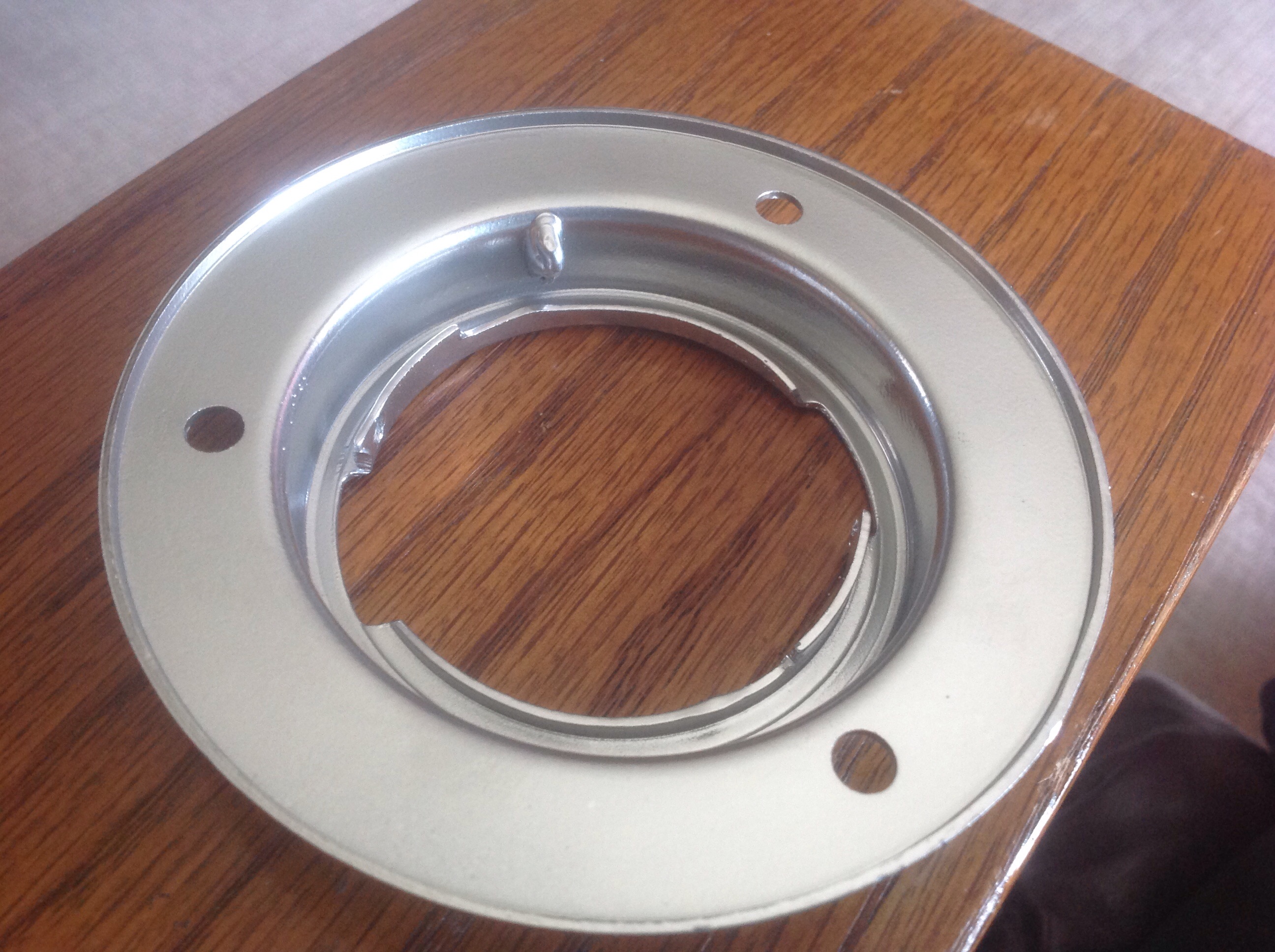
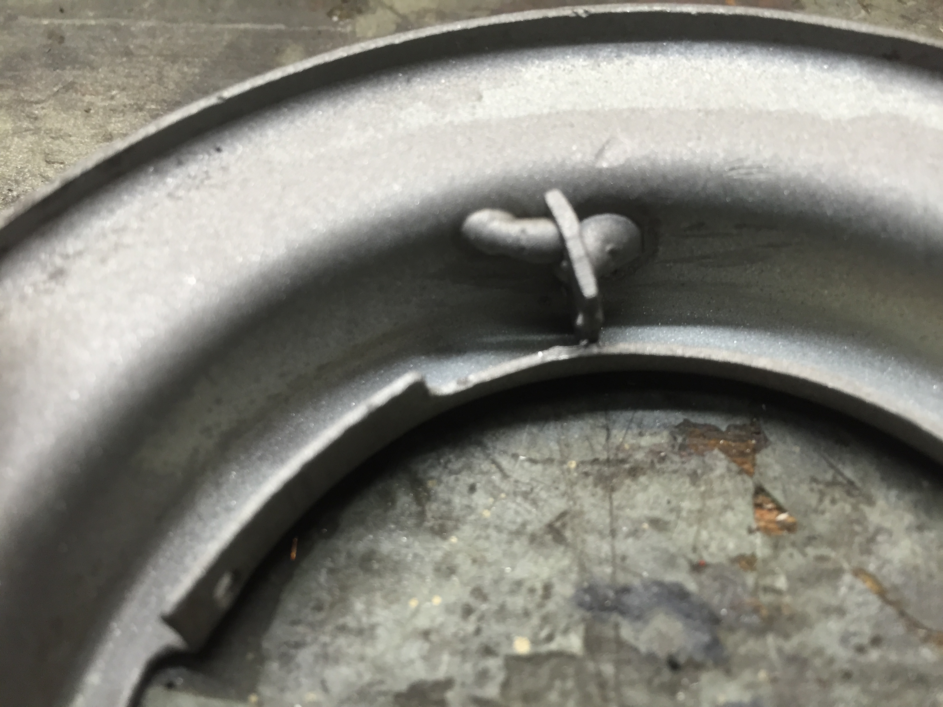
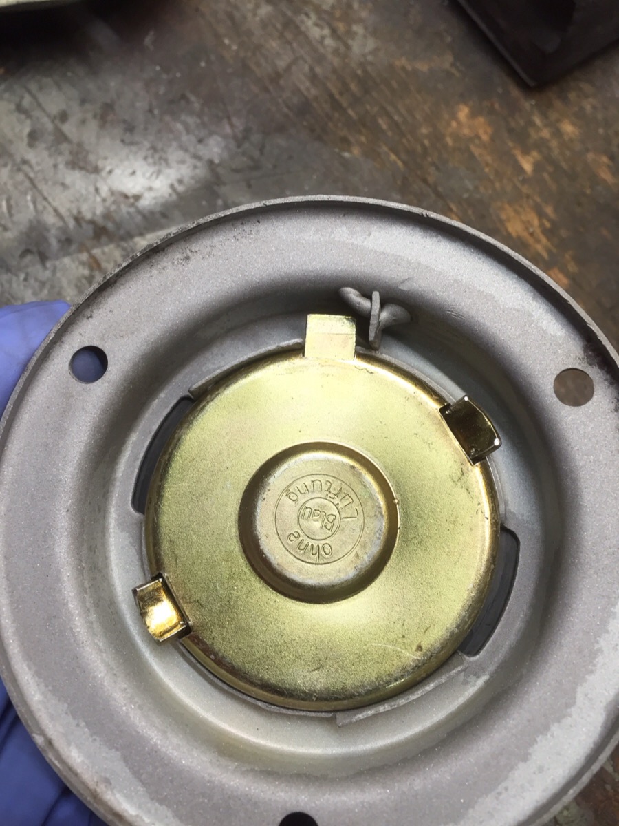
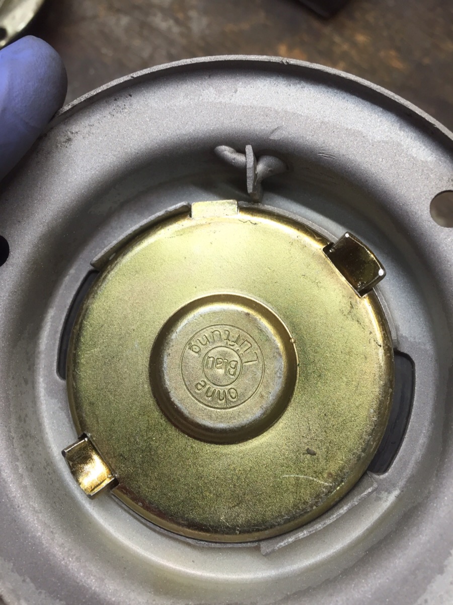
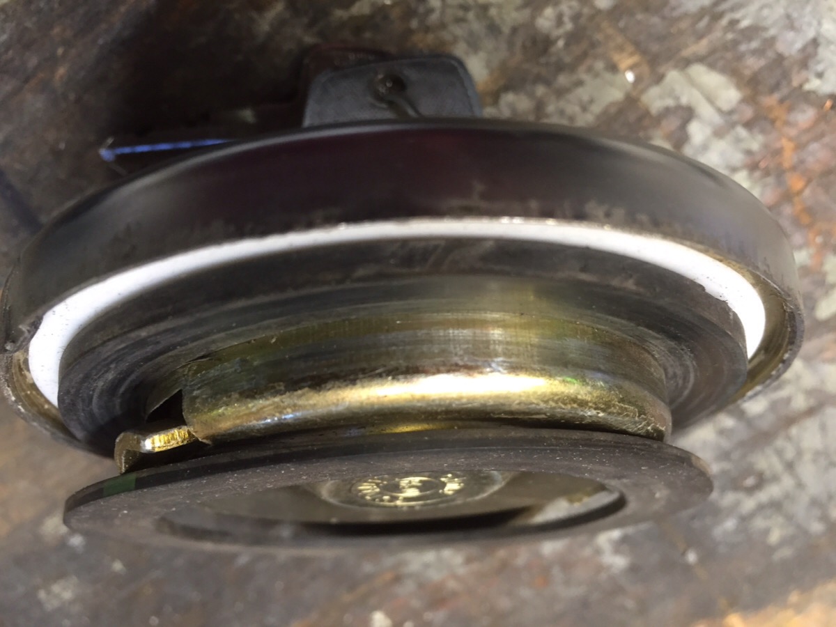
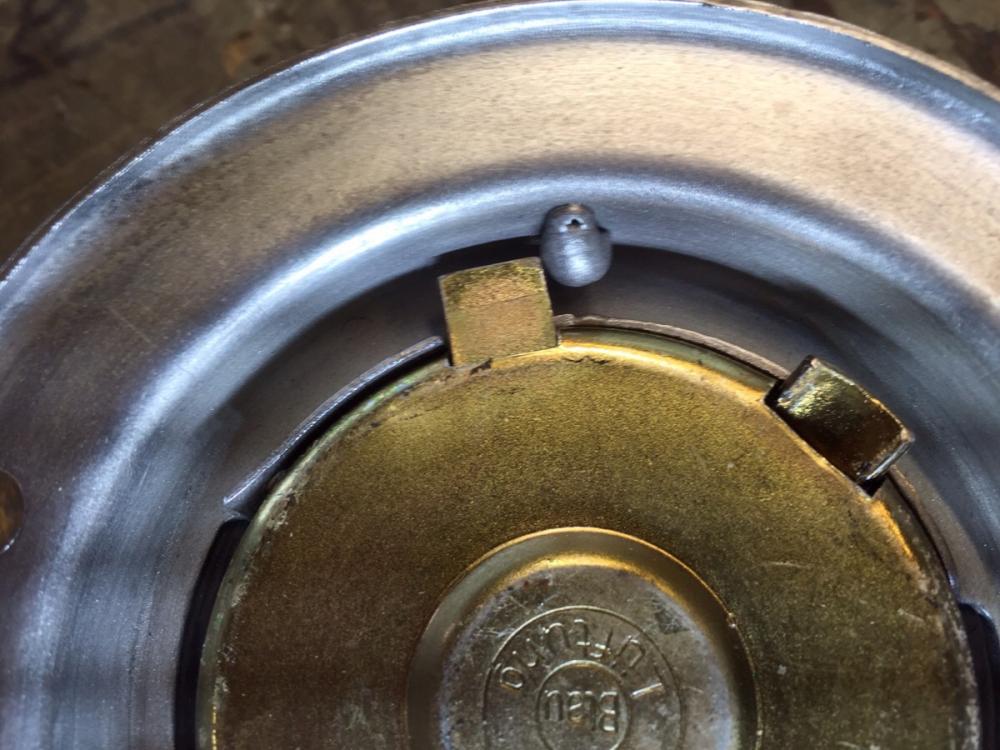
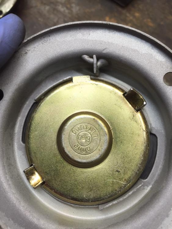
OMG Steve, ROFL, I'm just recovering now about the Chevy Chase scene... Oh my aching sides I've learned my lesson with you guys for sure. Ok, after staring at the ring and BMW cap for 10 minutes, the solution is really pretty simple. You just need a stop block at the right spot. Pictures are worth 1176 words.. First weld in a scrap of metal, here. Put BMW cap in, twist to stop position, turn key to lock, lock tab now protruding and trapped behind welded in tab. A pic with the key in open position, free to turn CCW to unlock. Had to use the rubber gasket from the stock cap, which is thicker. The tabs on the BMW cap are angled away from the body and will leave the cap loose if you don't have enough gasket thickness. Stock is about .012, BMW was only .08 ish Another issue is the cap OD verses the ID of the mounting ring. Dang tight fit. I just did a little hammer tap tap around the inside to roll the lip just a smig and it slips in easy. Ok who wants a modified mounting ring? Choice of powder coat, CAD plated, spray paint or sand blasted bare DIY.


-
Steve, yes the OD of the BMW cap as it fits in the ID of the filler ring is a very snug fit. Wouldn't take much of a tweak of the ring to make it too tight. As to the venting, I believe these caps are not vented. there is no obvious opening. Mind you, I can blow into the lock cylinder area, lips sealed around it (no comments....) and air comes out somewhere inside the cap. Can't tell if its through the locator or locking tab openings or between the inner and outer layer. Will have to do some testing.
-
Thank god I'm not the only fool who bought that BMW cap. What a scam! Yes, it "locks", yes it "fits", just doesn't lock to the car.... Man. However, I just pulled it out of it's hidey hole, and grapped a gas filler opening ring to understand how this looks and why it doesn't lock.. I may see a way to modify the ring so these caps actually lock.. Give me a day or two to fiddle....
-
-
I just received and installed the latest and greatest BlueToorth version of the distributor. Absolutely love the thing. The iphone app for it is designed very well and works great.. It is SO much better to have this on my iphone rather than having to drag out the old laptop and USB cable to tune this thing. The real time gauge displays of advance/RPM/Vacuum/temp/Voltage is very slick. It's also able to display GPS speed from your phone's GPS system. Nice integrated analog gauge display. It even has a cool security feature. You can disable the distributor from the app with one click and turn it back on when you return! Just remember to change your Bluetooth PIN from the default or anybody can defeat that. It does allow you to alter the tune when driving, but only to either add or remove timing. So a proper review would not be complete mentioned a couple of backward steps. They have removed the "dual tune switchable while driving" feature, and the ability to save and restore a library of tunes. You can only have one timing and vacuum advance map in the device, and you can't store it and retrieve another. Not sure if I think this is a problem, the real time advance up/down ability compensates for some of what's lost. Anyway, generally very pleased! Thanks Ed for the great service.
-
Right Size, Great Handling, Available. Pick two. Well except, Right Size and Available.... or Right SIze and Great Handling.... Wait....
-
Definitely watching. There are more than a few "purists" on here with quite stock restorations that should share what they've shod their beasties with... Zup etc?
-
Yes. The cap has an arrow on it that is to face forward, and is a snap on loose fit.
-
I'll put my 2cent bet at a rather large vacuum leak.
-
Recently discussed including a new option
-
DOT 3 brake fluid is a wonderful paint remover (look at your brake vacuum booster and below the master if you need proof) and will not harm plastics. Give it a shot.
-
-