Leaderboard
-
conedodger
Free Member8Points12,513Posts -
Captain Obvious
Free Member7Points10,081Posts -

cgsheen1
Free Member2Points690Posts -
HusseinHolland
Free Member2Points1,031Posts


Popular Content
Showing content with the highest reputation on 08/18/2024 in all areas
-
4 pointsOh, and forgot to say.... It looks like a graceful crash landing recovery so far. Glad to see that!!4 points
-
1 point
-
1 point
-
1 pointHi, Yours is for the later ‘U shaped’ lower cross members which can be seen on 280Z and Fairlady Z(S31 model). Just FYI, I recently refurbished my pan for my Z which is the earliest style, no-hole version (late 1969 to late 1972 in Japan). Kats

 1 point
 -
Jalex's NGK plug wires are almost new. I like the idea of replacing the dizzy. Will the coil he's currently using (snort) be OK with the new dizzy?1 point
-
1 pointAnswers to some of your questions that I haven't seen answered already: 2) Yes, it's that easy. (And I'd be interested in the relatively new hoses if you're looking for them to find a new home. Send me PM if you want.) 3) Those things are supposed to hold the throttle open a tiny amount when you are decelerating hard. You probably won't notice if they are working or not. 5) In theory, nothing you are doing should have any impact on the carbs or the tuning. 6) Probably, and probably.1 point
-
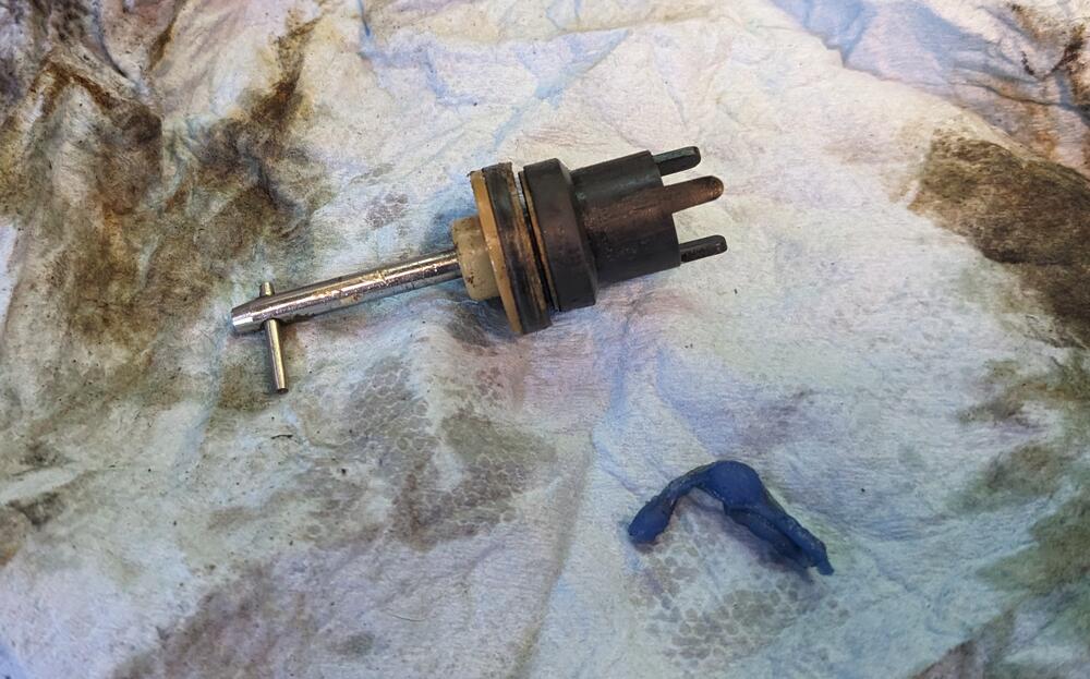
1 pointI stumbled on a real one. Nothing but the pcv valve and the booster port mounted vertically. I don't think there's even a plug in the old horizontal booster port out the back. Smooth all around.1 point
-
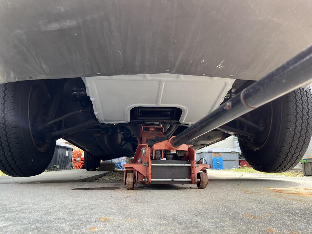
1 pointI don't think that's true. You know that the early 260Z (like mine) has a 240Z radiator core support. The late 260 and the 280 changed the lower support downward in a sort of deeper "U" fashion. Since the "belly pan" attaches to both the frame rails and the bottom of the core support, there has to be a difference in design for the pan. A quick look at the parts list on carpartsmanual.com shows "splash-board engine" with one part number (74810-E4100) TO 08/74 and a different part number (74810-E4200) FROM 09/74. The same part number for the early 260Z shows up for all 240Z's which I would expect. I'll look at the three that I have and see which part they are. If I have one of each, I'll post a pic with the physical difference.1 point
-
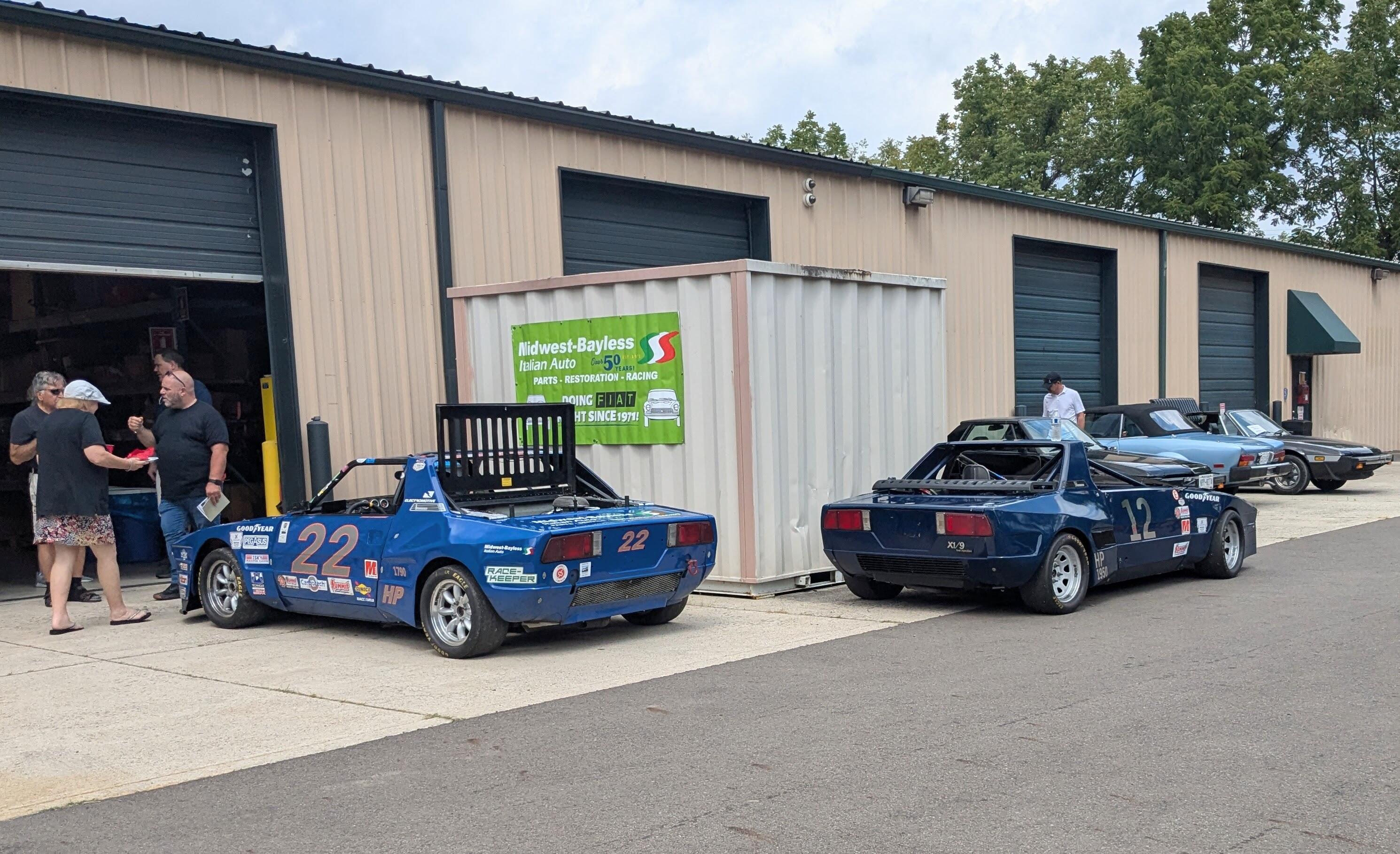
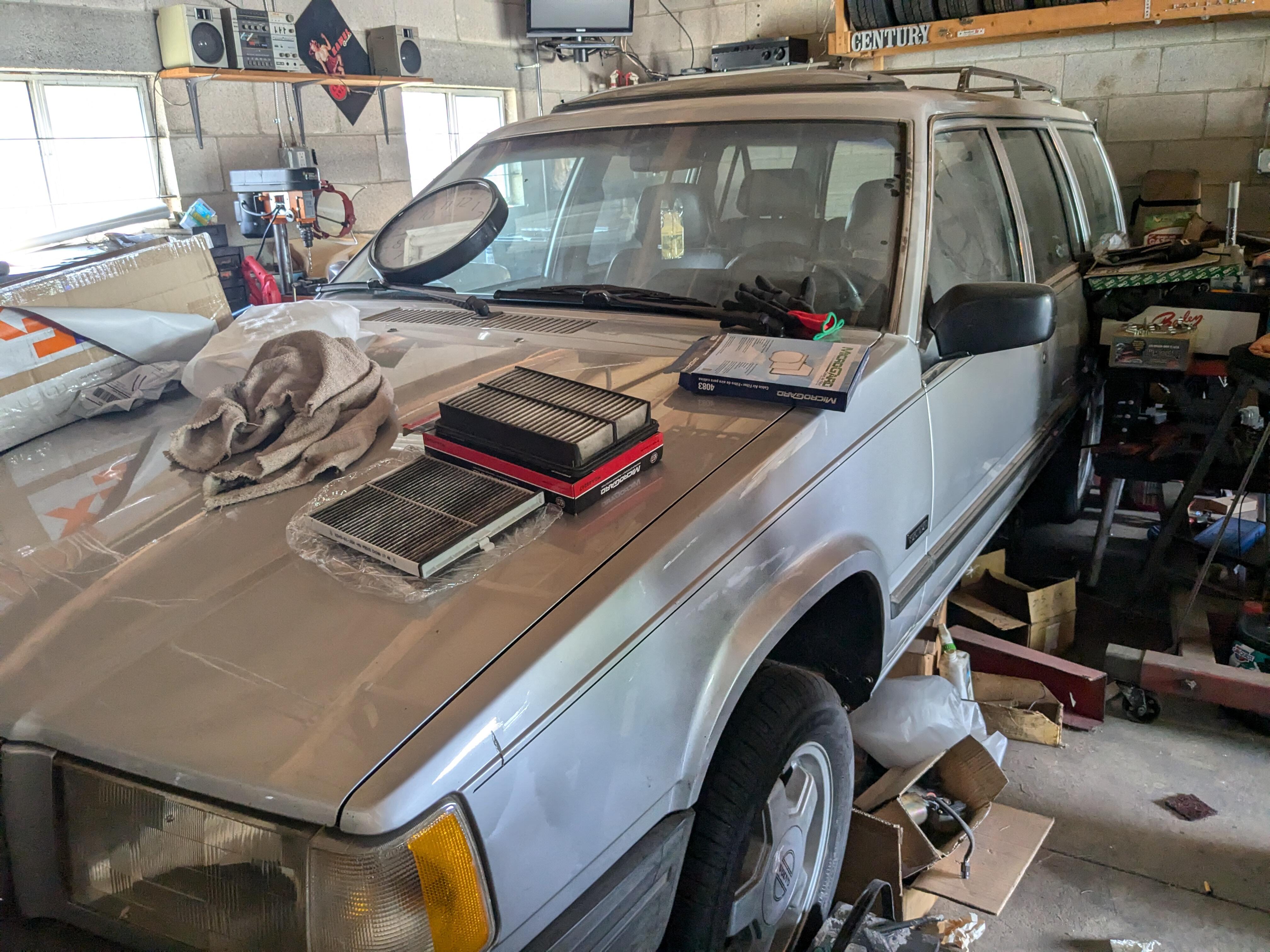
Car has run beautifully all the way out to Columbus, OH. about 600 miles so far, mostly 65-70 highway speeds. It has consumed about 1/2 quart oil, which I haven't seen in local/mixed highway driving. Couple of the Fiat race cars at the Fiat Meet One of the older techs at the shop was previously a Volvo guy, and has a 90 740 16V wagon he wants to move out of his garage where it has been stored for th past 18 years. I may have to buy it Needs the head re-installed - he is now physically unable to do the work, hence the desire to see it go to another Volvo guy.


 1 point
 -
Another stunning example to test the health of the market https://bringatrailer.com/listing/1970-datsun-240z-125/
 1 point
 -
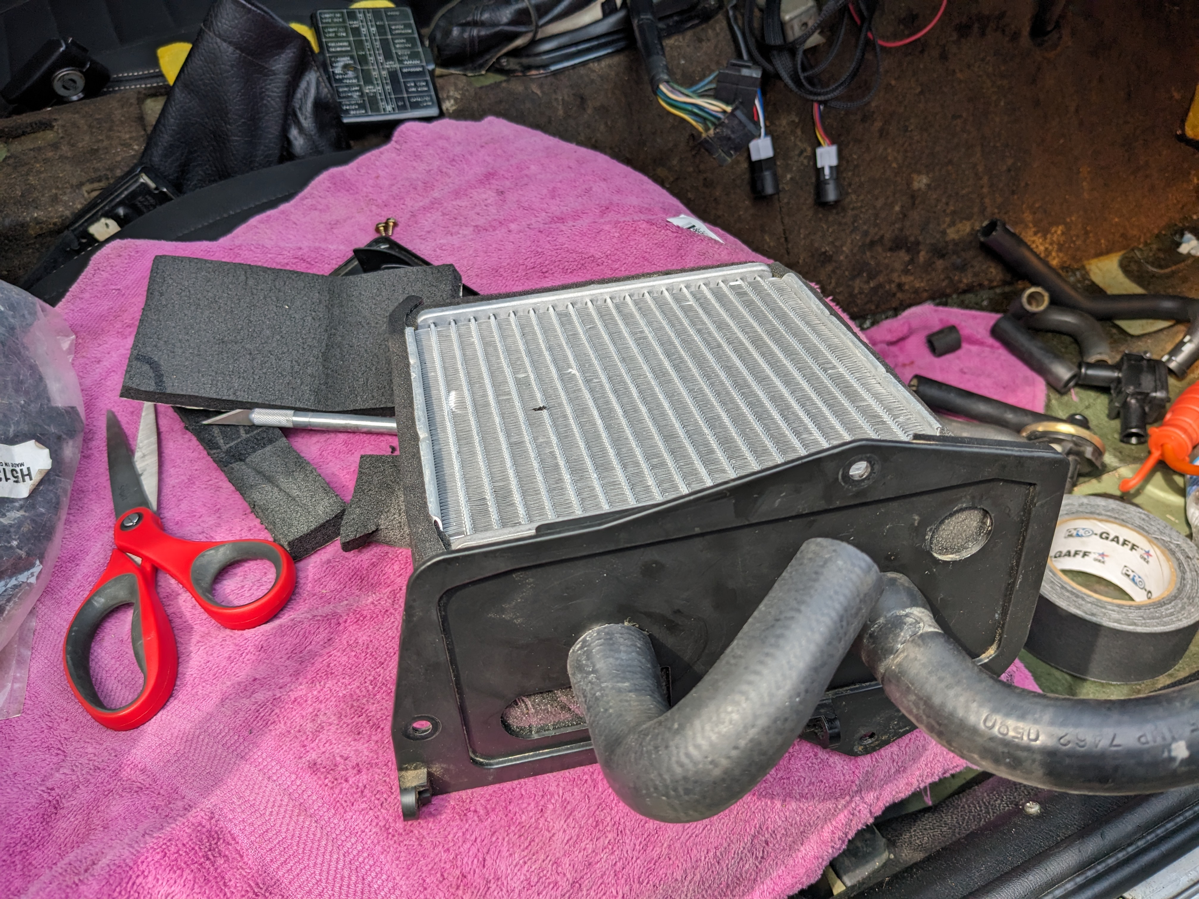
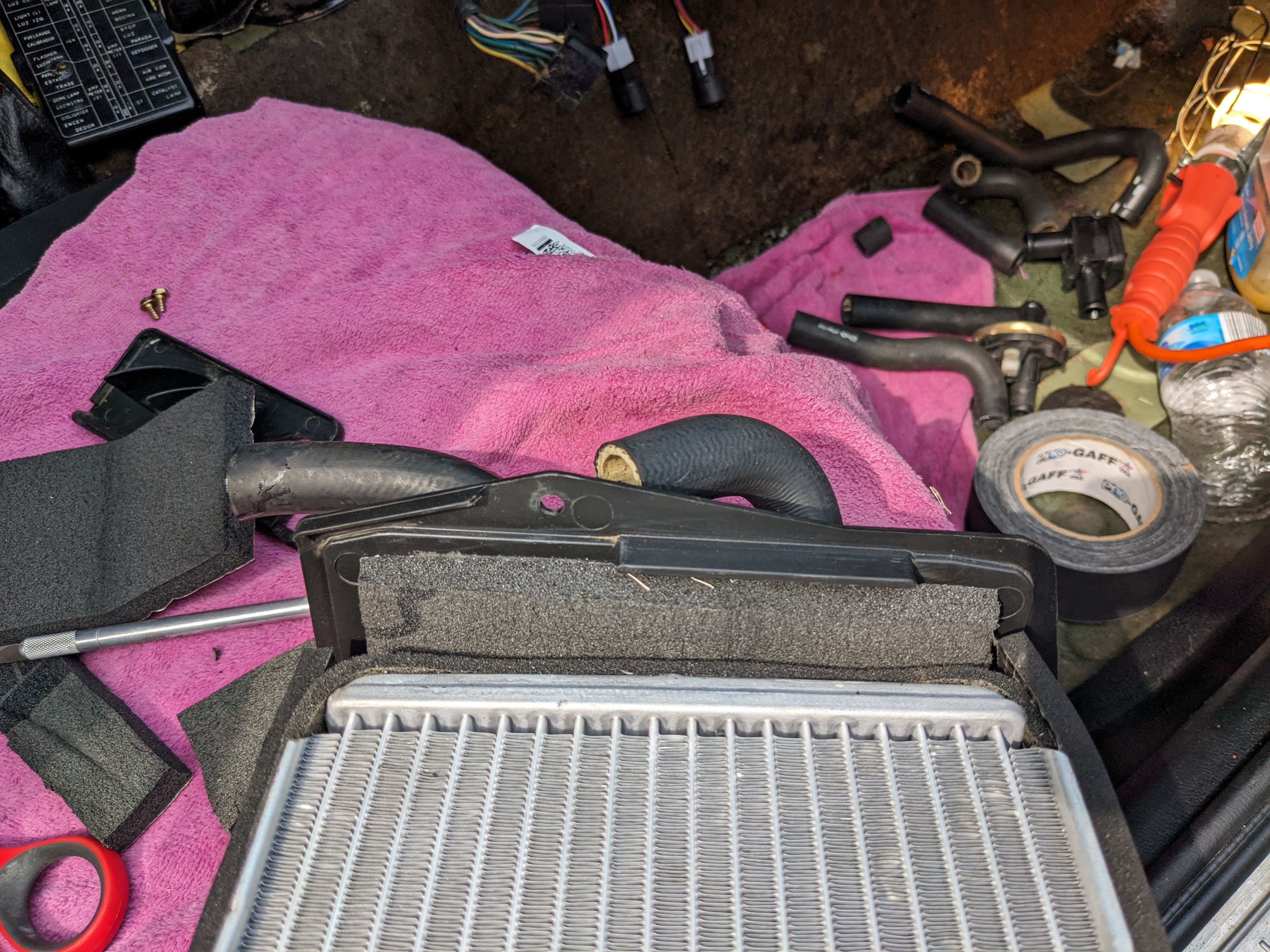
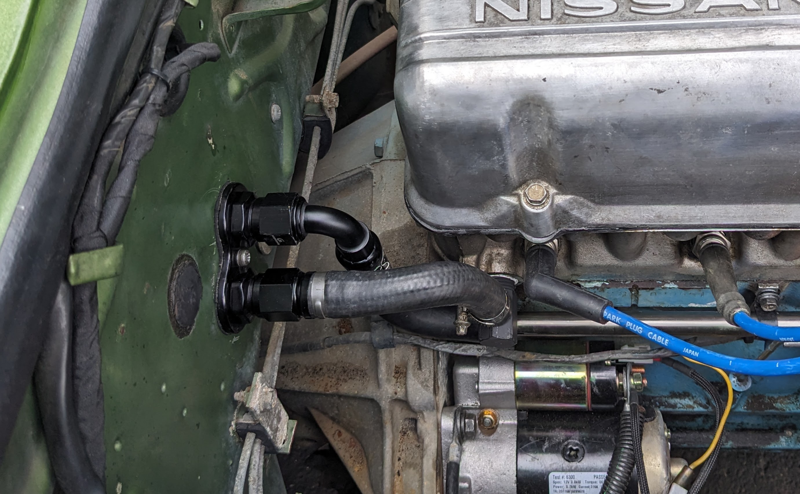
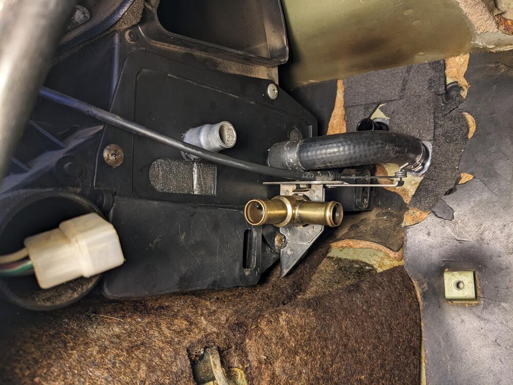
So to continue with my version using the '91-02 Ford Escort heater core (thanks Capt. Obvious!) I ordered the heater valve mentioned by another -4 Seasons 74627 - but it didn't arrive until late this evening, so I dismantled the original & had a go at fixing it following the other thread Think it's pretty clear why the heat never shut off - large chunk of silicone wedged in there I forgot to take pics of the re-assembly, I used a Viton o-ring in place of the square cut outer seal, I left the inner one alone. Left it set on an angle filled with fluid to check for leaks. This is what my phone screen looks like (actually worse now, it's all dark) - so my pics are hit & miss I flipped the I/O for the heater hoses - the bulkhead upper is now the return & the outer/lower is the feed. I did it this way so that the feed is not too short, and the return is a straighter run. and so the inside feed is a plain elbow 90º. Determining hose lengths (cut from Volvo 700 formed hoses) here. SS tubing is 20.5". dogleg for the other end, test fit alignment of pipe & hoses Hoses cut & clamped (head fitting was removed, de-rusted, sealed & reinstalled, slight offset change -more vertical Far end adjusted & clamped With that end out of the way, I returned to the heater valve & core. Eyeballed holes for core pipes, based on the core being centered. Added closed cell foam on the sides to make it snug, and to the front to keep it pushed all the way in & cover up the old pipe holes. Was playing with hose routing - this way was to allow the 74627 straight pipe valve to sit above the feed pipe along these lines I'll revert to this layout if I need to switch to the 74627 valve When it became clear that the 74627 wasn't coming , I switched gears & worked on fitting the original repaired valve - Heater valve fitted using the upper existing mount screw, new hole drilled in plate. Cut a notch in the valve mount bracket to clear the lower screw. Checked that flap can open. Feed hose clamped. Cable attached & function tested. Test fitting (formed, Volvo) hoses to & from heater valve Added oetiker clamps after this. Since I wasn't able to flare the end of the core tubing, I prefer them as the clamping is typically more uniform than a worm clamp of any type.


 1 point
 -
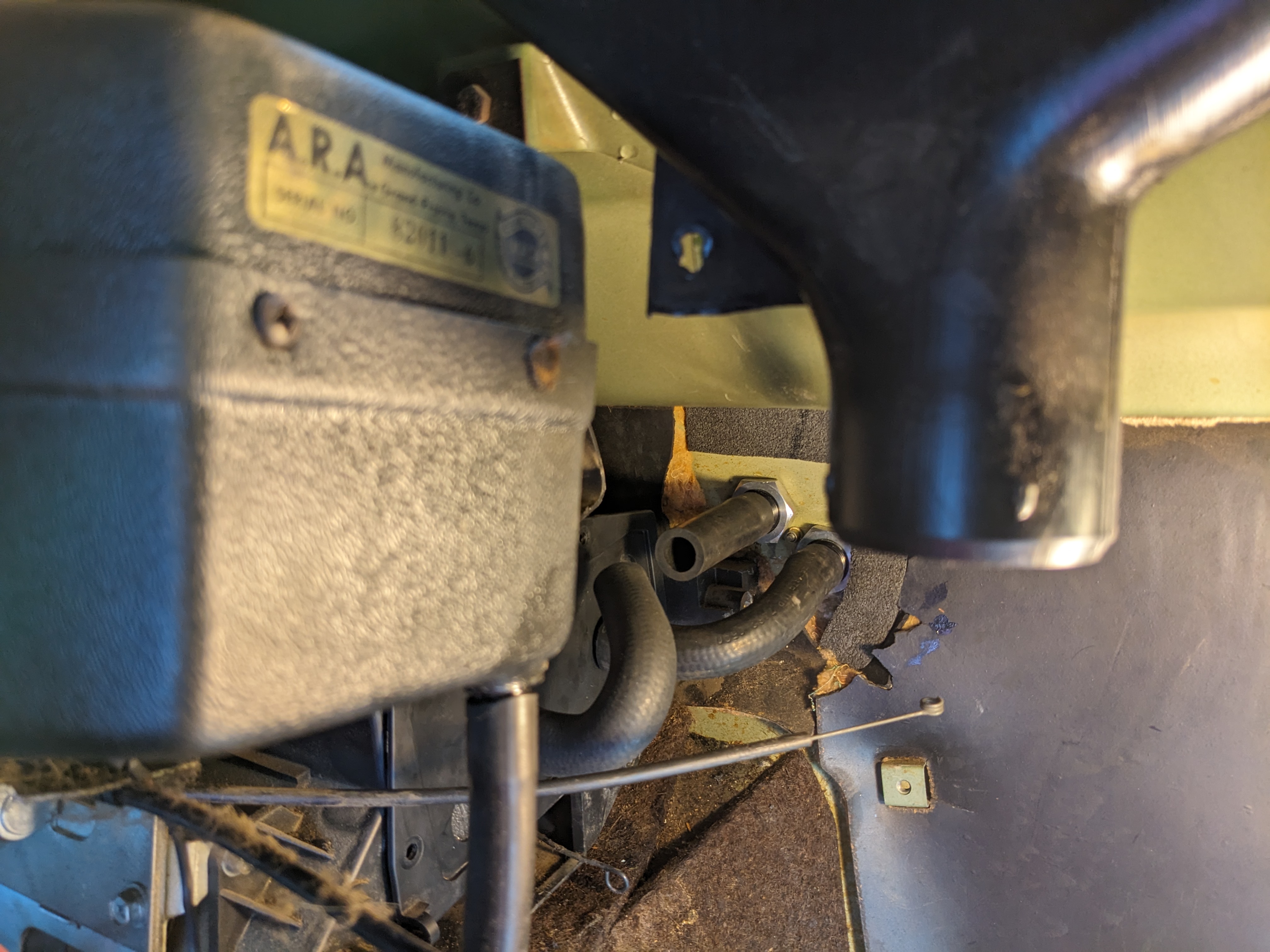
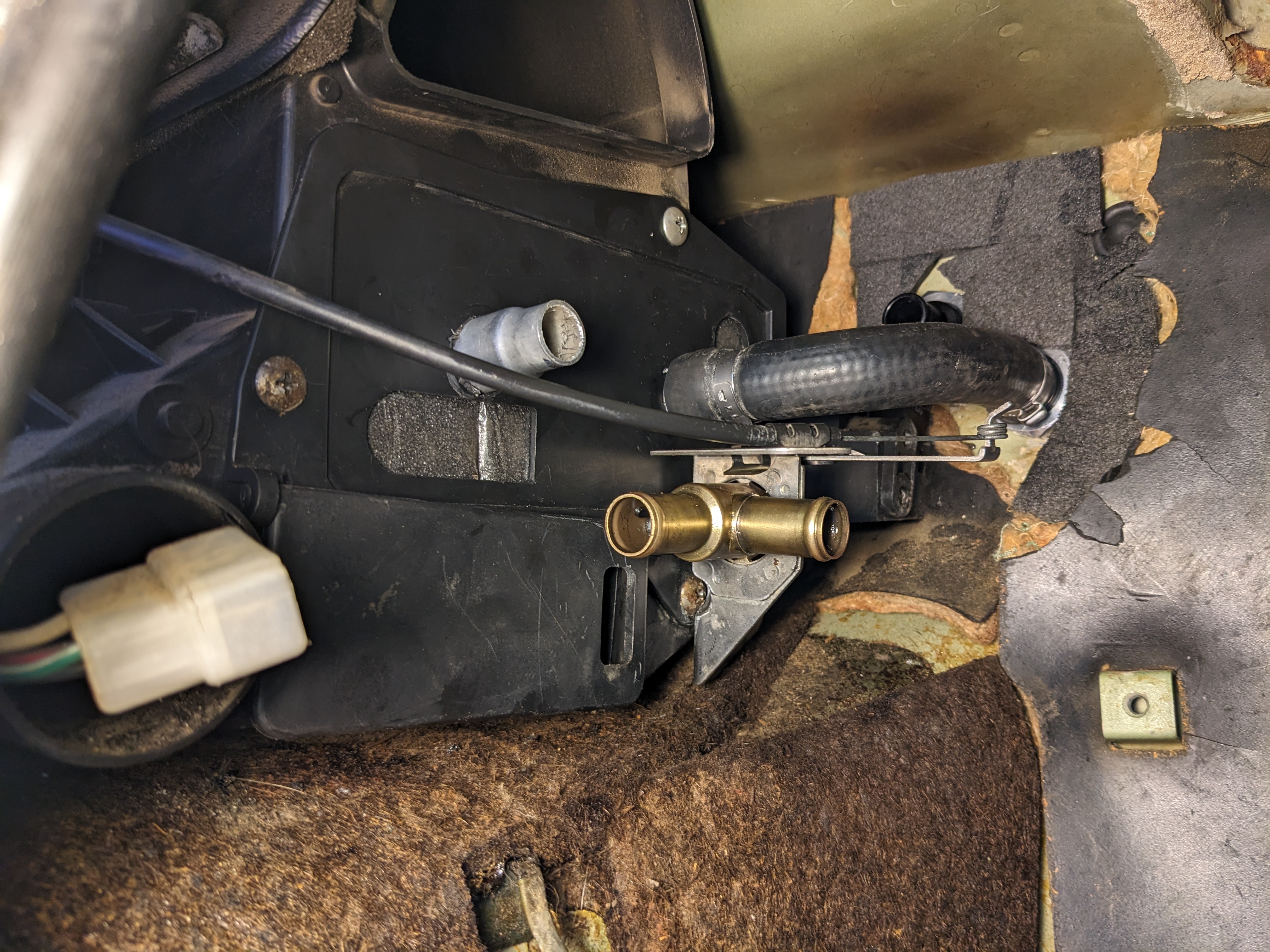
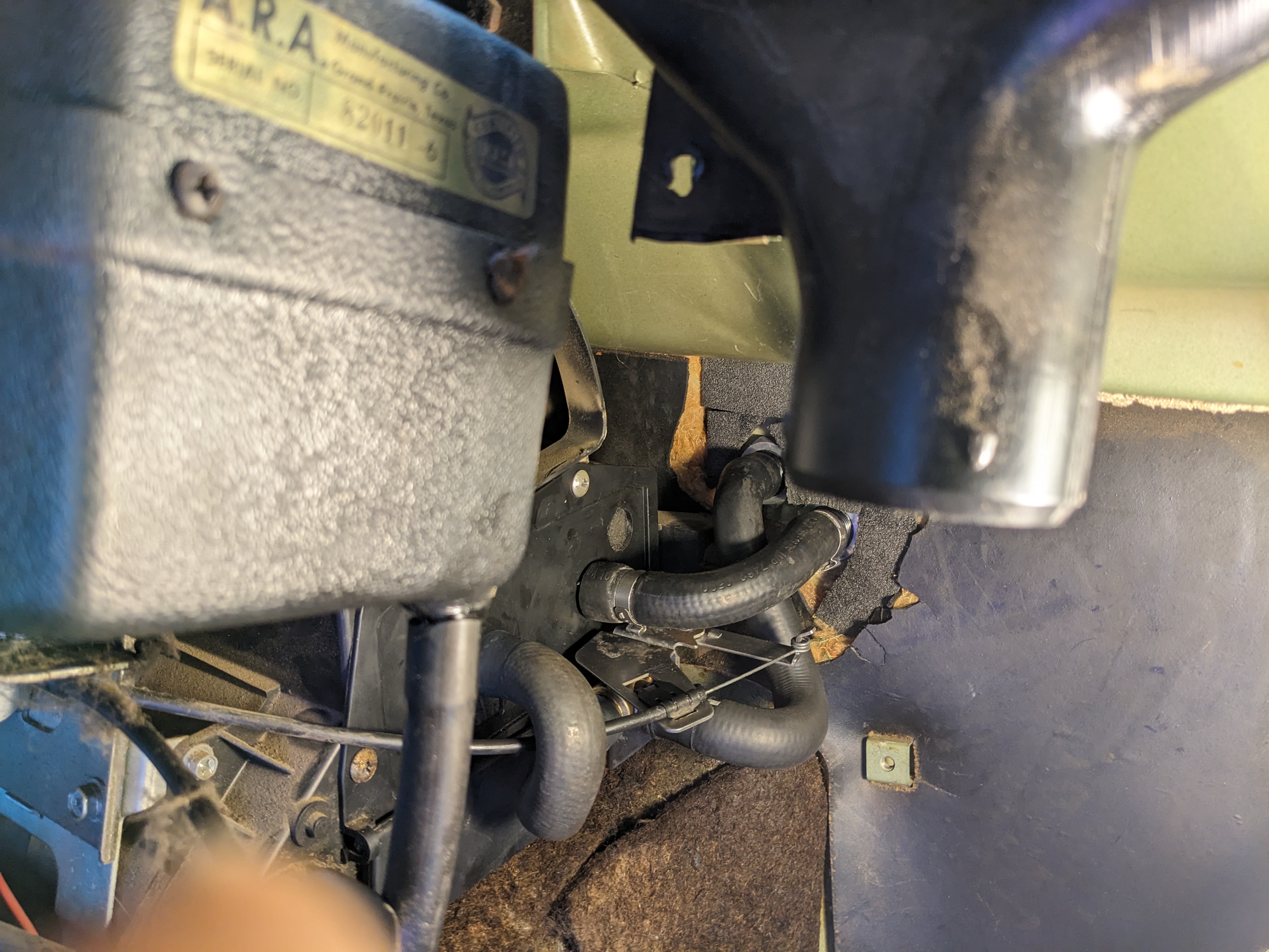
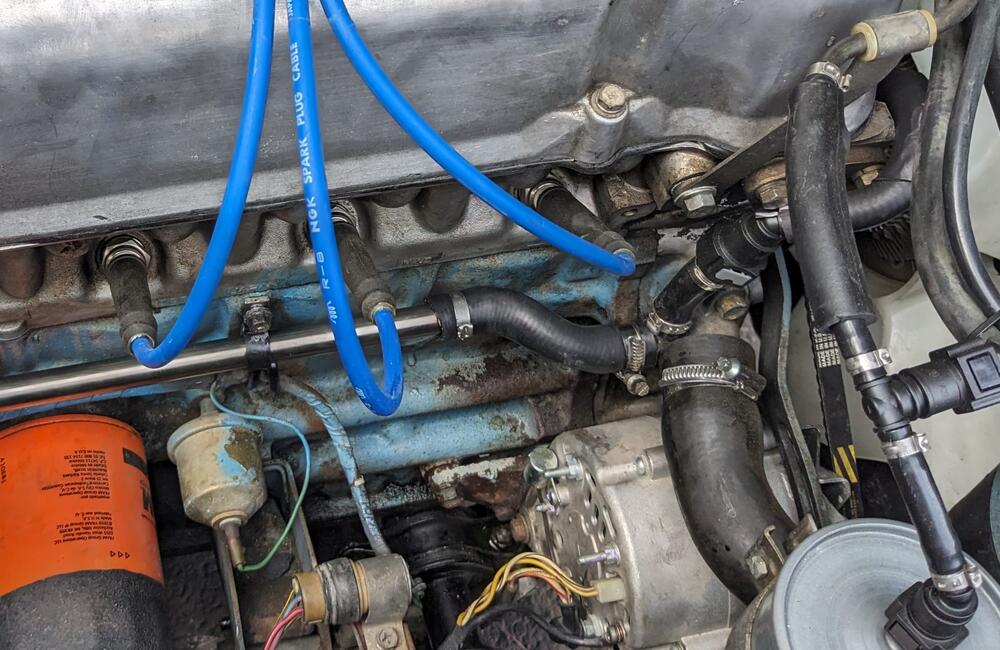
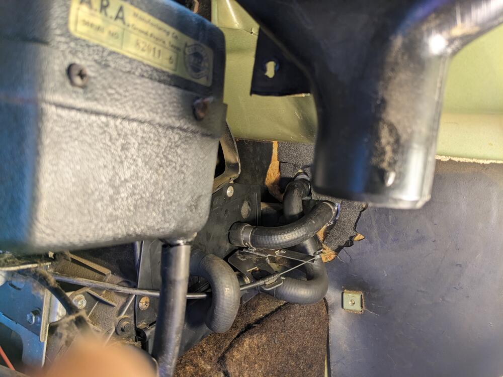
Reloaded pics: The heater in my 77 always blew hot regardless of where I put the temperature slider and I tracked the problem down to a faulty water cokk valve under the dash. I had the capillary style valve (http://www.classiczcars.com/forums/thread46448.html) and spent a little time looking into a direct replacement, but after spending that kind of "quality time" working under the dash, I decided that I never wanted to go through that again. So I changed over to a ubiquitous newer style water control valve which I relocated up in the engine compartment instead of under the dash. I grabbed a bunch of different valves from the junkyard from various Honda and Toyota products, trying to find one that had the correct flow direction, had the lever on the proper side, and opened when the cable "pushed" instead of "pulled". I kinda lost track of which was which, but I believe the one I finally used was from a 2000 Acura TL. Here's the valve I used. Flow direction is left to right when lever is on the side pictured, and it's CW to open again with lever as pictured. That means I can mount it on the return line from the heater core and it's push to open. Note that I also had to make a new control arm for the valve to get the ratios correct between between the travel distance of the control slider and the travel distance of the new valve: I'm sure there are much simpler ways to mount a valve and connect to it but here's what I did. I made a mounting bracket for the valve which also included the provision for attaching the cable control: Here's the whole thing painted, mounted, and plumbed in the engine compartment. I attached it to the mounting bracket for the brake lines and fed the control cable through an existing hole in the firewall. I believe this hole is where the vacuum line goes for the HVAC system on cars with A/C. The hole location was a little higher than optimum, but since I don't have A/C, this hole was unused which saved me the trouble of drilling a new hole only to find out that the whole project was a mistake: It wasn't a mistake! It works great and will be a breeze to work on in the future if necessary.1 point
-
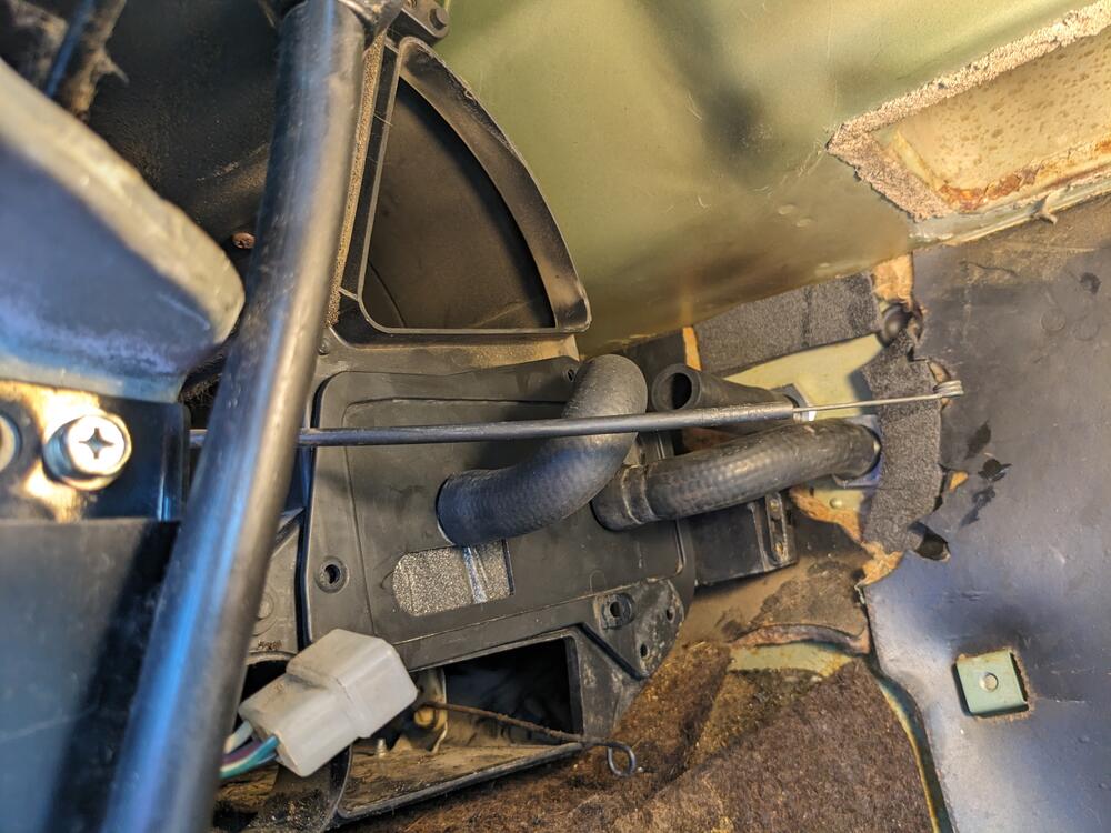
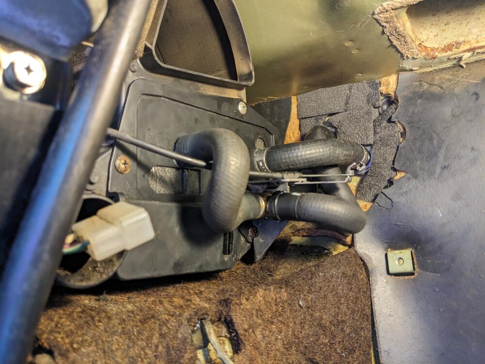
Here's a summary with some reloaded pics. Heater core for a 91-02 Ford Escort SOHC (not the ZX2). The heater core is aluminum, and the one I got was Spectra Premium P/N 94741. I decided on the Escort core because it was the thinnest, smallest, most generic, cheap core that I could find with tubes that stuck straight out on the same side. No long funky bent tubes. No weird mounting flanges. Generic, small, thin, and cheap because it's from a ubiquitous car and not from a low volume hard to find Ferrari. Here's a pic of the Escort core next to the original 280 core: Escort core with a layer of foam around the outside for a snug fit inside the air box: Build a little shelf for the Escort core to sit on. Since the Escort core is a little thinner, it allowed me to move the core up a little so it doesn't interfere with the floor duct control linkages at the bottom of the heater box (like the stock one does). Aluminum angle material screwed into place as a lower support shelf: Escort core in place before putting on the access panel cover. Can't see it in the pic, but it's resting on the new aluminum shelf on the far side: Cut some new holes in the access cover for the inlet and outlet tubes and put the cover in place. Tape over the original holes so air doesn't come out where it's not supposed to. I put a support shelf on the back side of the cover for that end of the core as well, but after doing that, I'm not sure it's really necessary. If I were doing it again, I would probably skip that second shelf and just use the inlet and outlet tubes poking through the cover as the supports on that end. But if you look carefully, you can see the heads of screws that hold the shelf in place: When I get a couple more minutes, I'll post some pics on how to make water connection to the core.1 point