Leaderboard

 Subscriber

Popular Content
Showing content with the highest reputation on 12/20/2021 in all areas
-
Not quite yet. The Badge isn't awarded until spindle pins are pulled.3 points
-
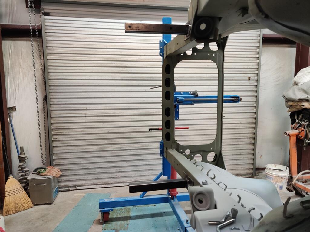
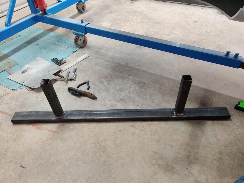
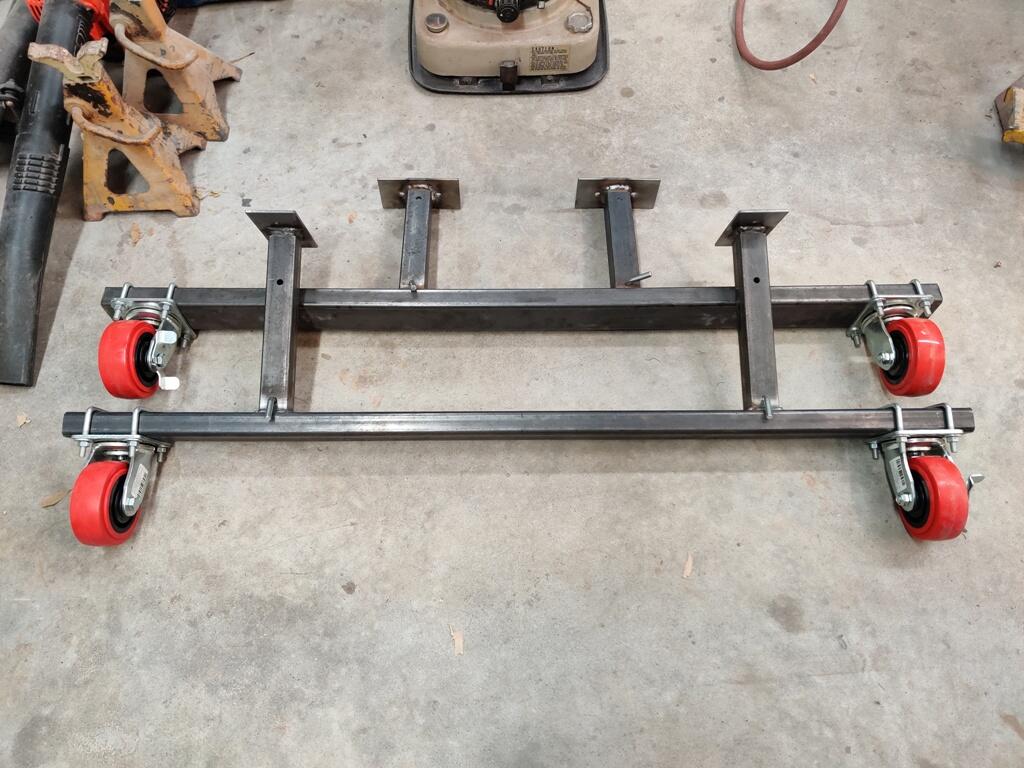
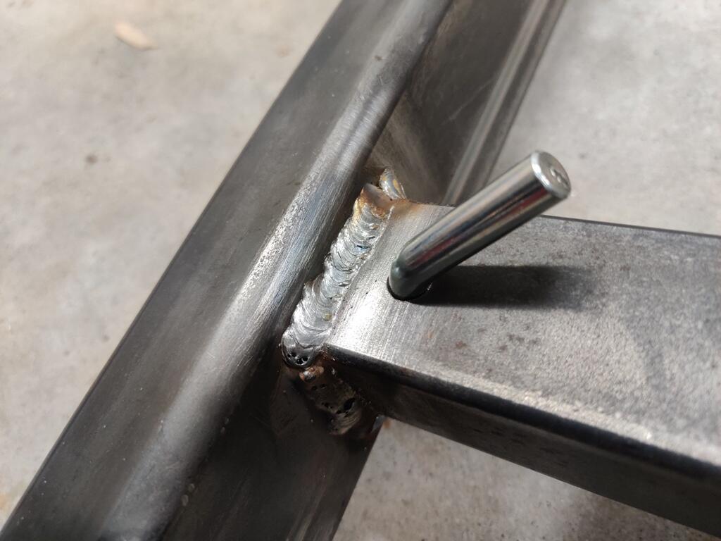
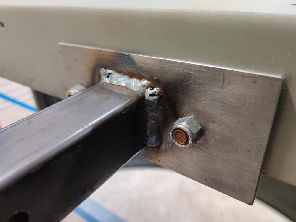
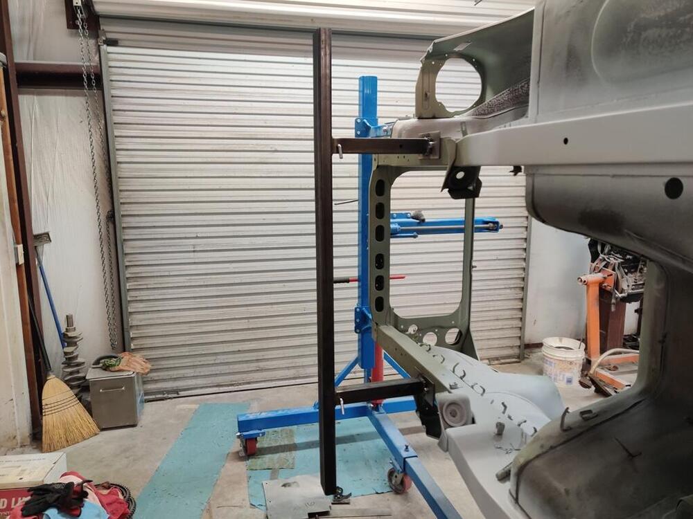
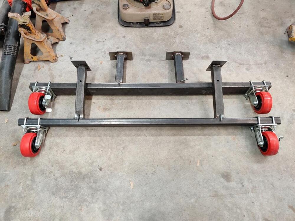
Today, I fabricated the front rolling frame assembly. The cross beam is thicker wall that the rear one - it is heavy. I didn't measure it, but the wall is about 3/16" - definitely thicker than the rear one which looks to be about 1/8" wall. When welding the square post to it, I had my little Miller Mig 90 maxed out. While welding, I would sit the end of the nozzle on top of the cross beam and wait and wait, and then kiss the edge of the square tubing and then back over the cross beam... and wait and wait, and then kiss the upright square tubing again. Easily spent 4 to 5 times as long trying to put heat into the cross beam to get penetration. The plates that mount to the car are nearly 3/16" thick. Though the welds could be prettier, I am confident they have good strength. It will be an exciting time when I get to use these as the car will be really close to being ready for paint. 😍


 2 points
 -
1 pointWe could go to what Mariners use... Port = Left side of car when looking to the front of the car from the rear and Starboard = Right side of car when looking towards the front of the car from the rear. 🤪1 point
-
I think at this point you will be rewarded with value even though it's not an early car.1 point
-
Also of note in the drawings is the location of the stopper screw. Early has it on the side #19 Late has it on the bottom #17 I concur that it is an early M/C GLWS1 point
-
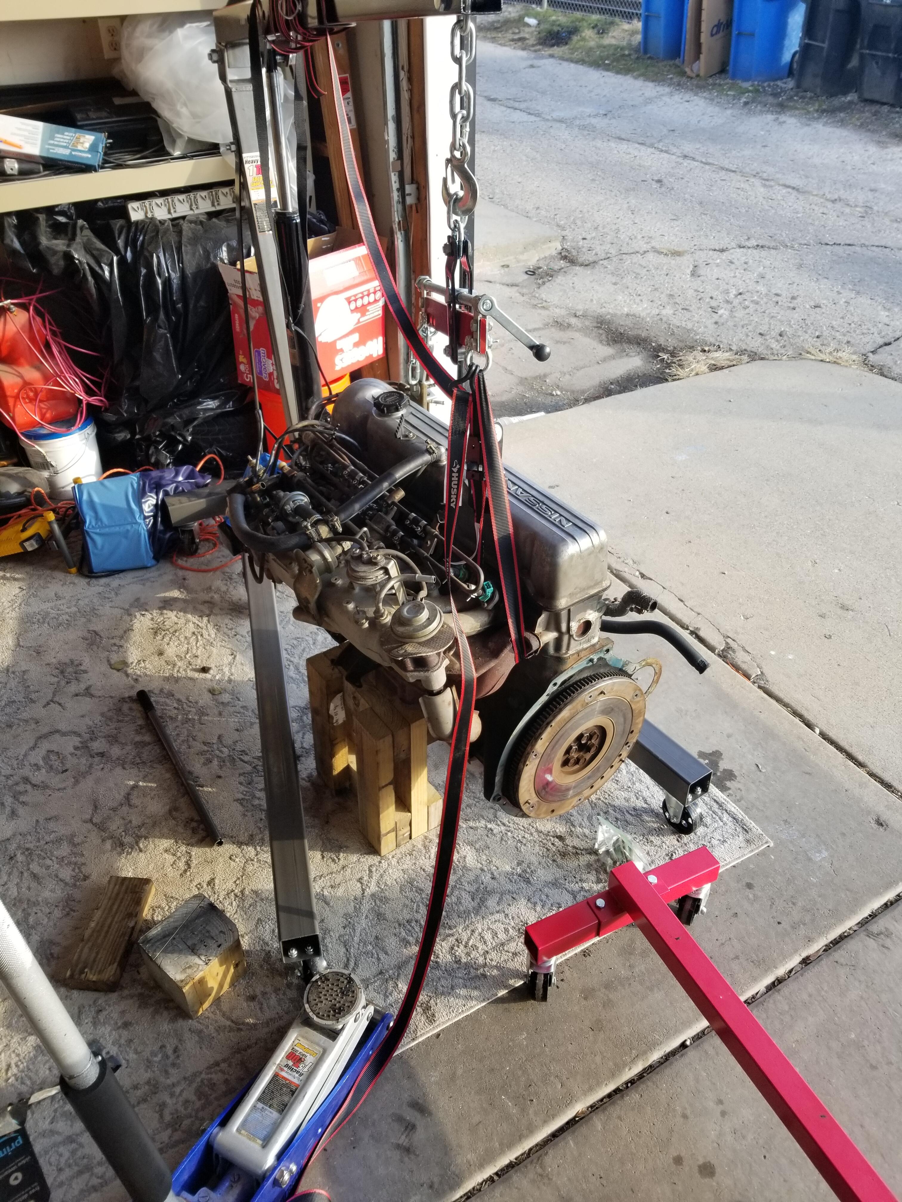
Thanks @siteunseen. Its a life long dream to do it so it feels great. I have it resting on two wooden stands under the bolts that connect the oil pan to the block. I don't have any junk tires at the moment, but will get it on the engine stand in the next 2-3 hours.1 point
-
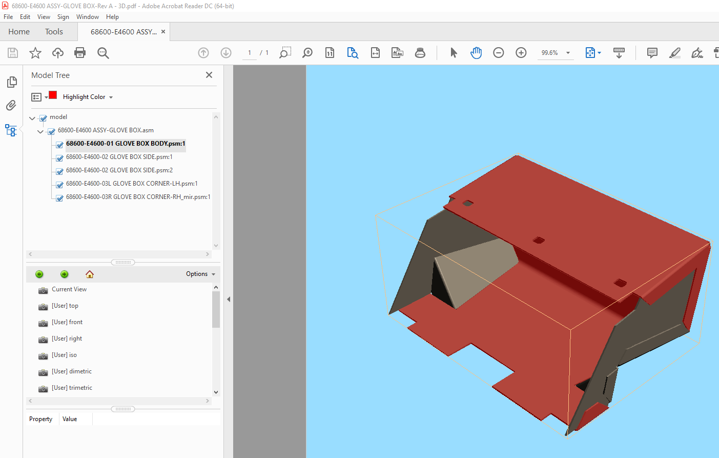
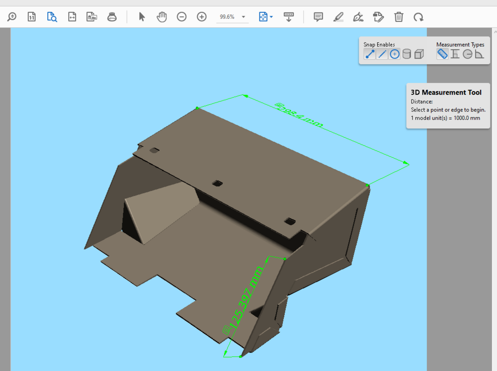
1 pointYou're welcome @Seppi72. My plan, as mentioned previously, was only to make a 3D cad model and 1:1 scale flat patterns. I was not planning to create a complete set of fabrication documents. Anyone with a 3D cad package should be able to pull off any other dimensions they might need from the step file I uploaded. If anyone wants a specific dimension checked, I will try to do that if asked. FYI, In the files I uploaded I also included a 3D pdf file that can be opened with any recent Adobe Acrobat Reader. The 3D pdf viewer allows you to rotate, pan and zoom etc. and also to see a model tree and isolate individual parts. You can even use the measuring tools by right clicking to see the options, Hope this helps Cheers, Mike

 1 point
 -
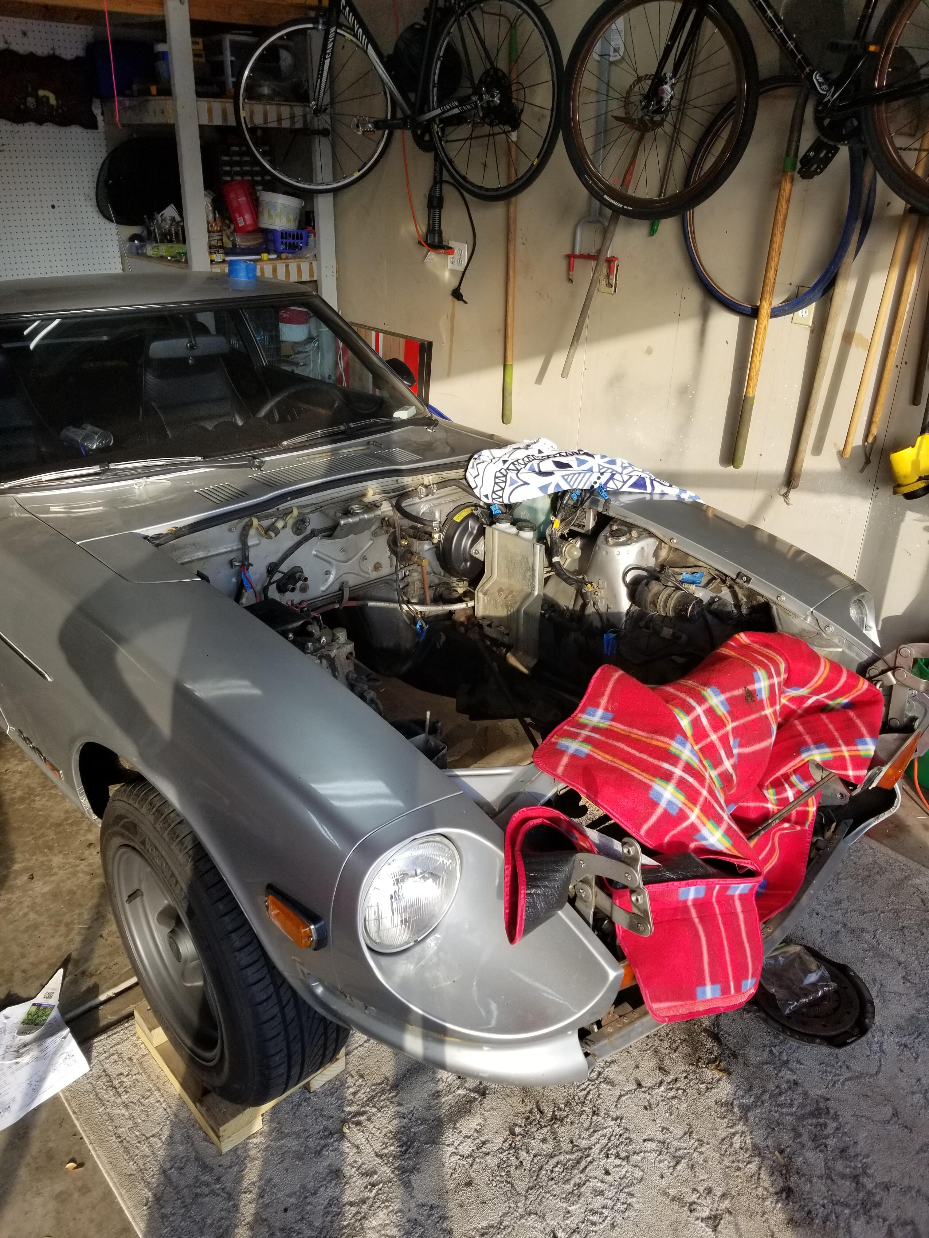
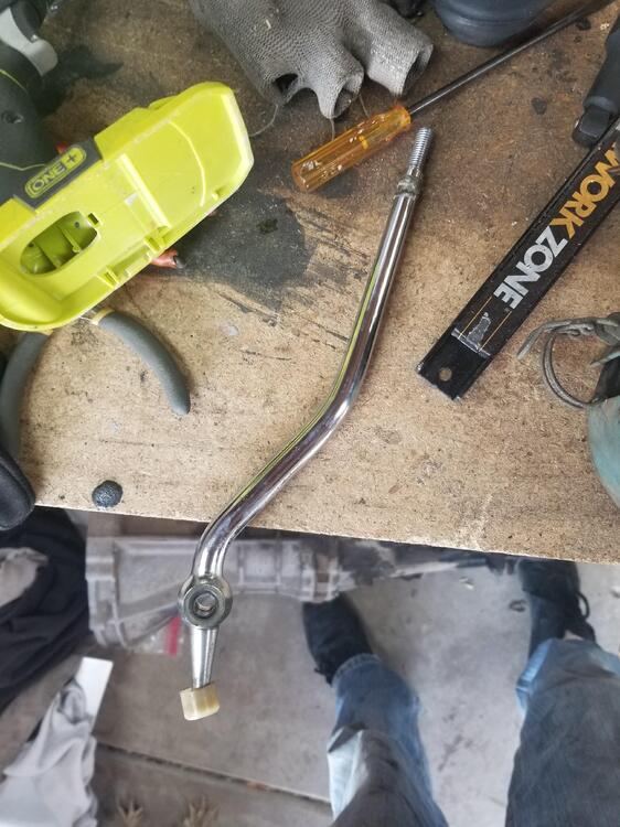
Safely removed! Just need to get some longer bolts to get it on the engine stand since the stock ones look like they are too small. Only one hiccups, forgot to remove the shift knob so I tore the rubber gasket which pissed me off becuase I just replaced it. Anyone have a photo of their shift lever? Trying to make sure I didn't bend it, but this thing has more curves then some women I have dated so it'd hard to tell :p

 1 point
 -
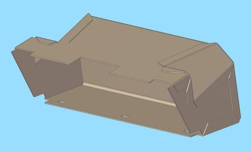 Templates and a 3D model (.stp format) for a 240Z glove box. the main formed body and flat sides were checked against disassembled and flattened original parts and are quite accurate. The smaller formed corner parts are not as accurate. Also included is a 1:1 scan of a tracing for the two formed corner parts, these parts were only roughly modelled and did not flatten exactly the same as the actual parts.Free1 point
 -
I happened across this and found it interesting. https://www.retrosoundusa.com.au/index.php?l=product_detail&p=363 Classic Auto Sound specialize in "turning back time" on your classic car radio. This conversion features music streaming & hands-free Bluetooth, AM/FM radio, USB & AUX inputs and more. The ultimate in period-look with today's technology. Anyone bought one?1 point
-
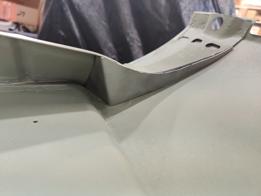
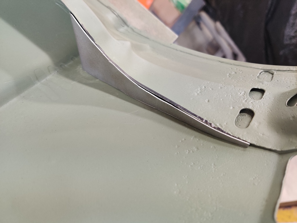
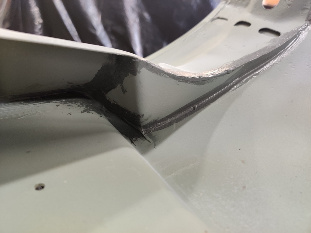
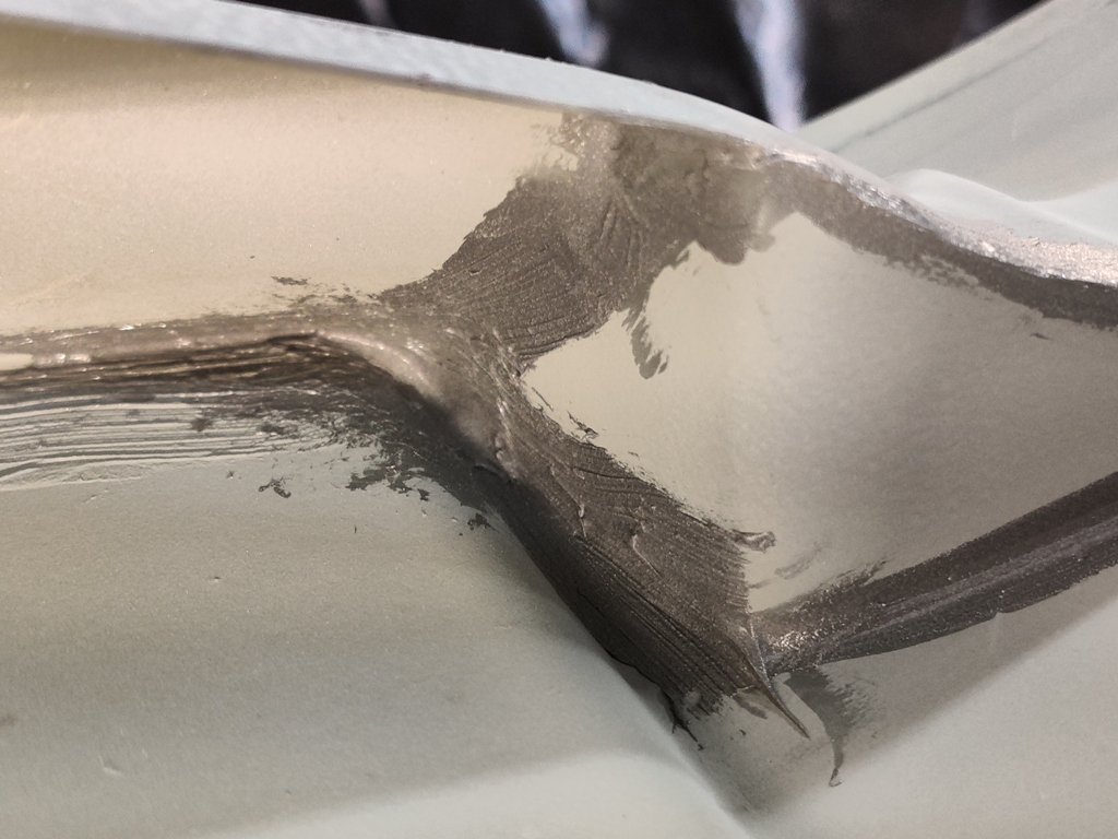
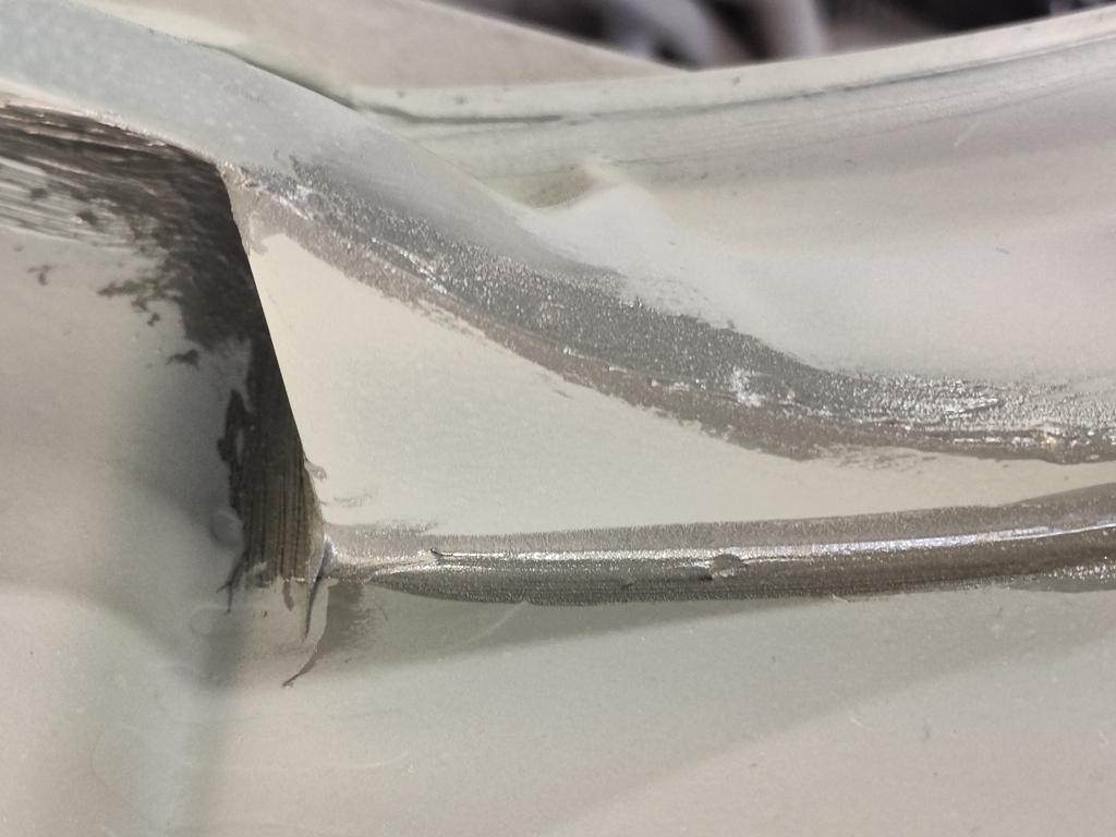
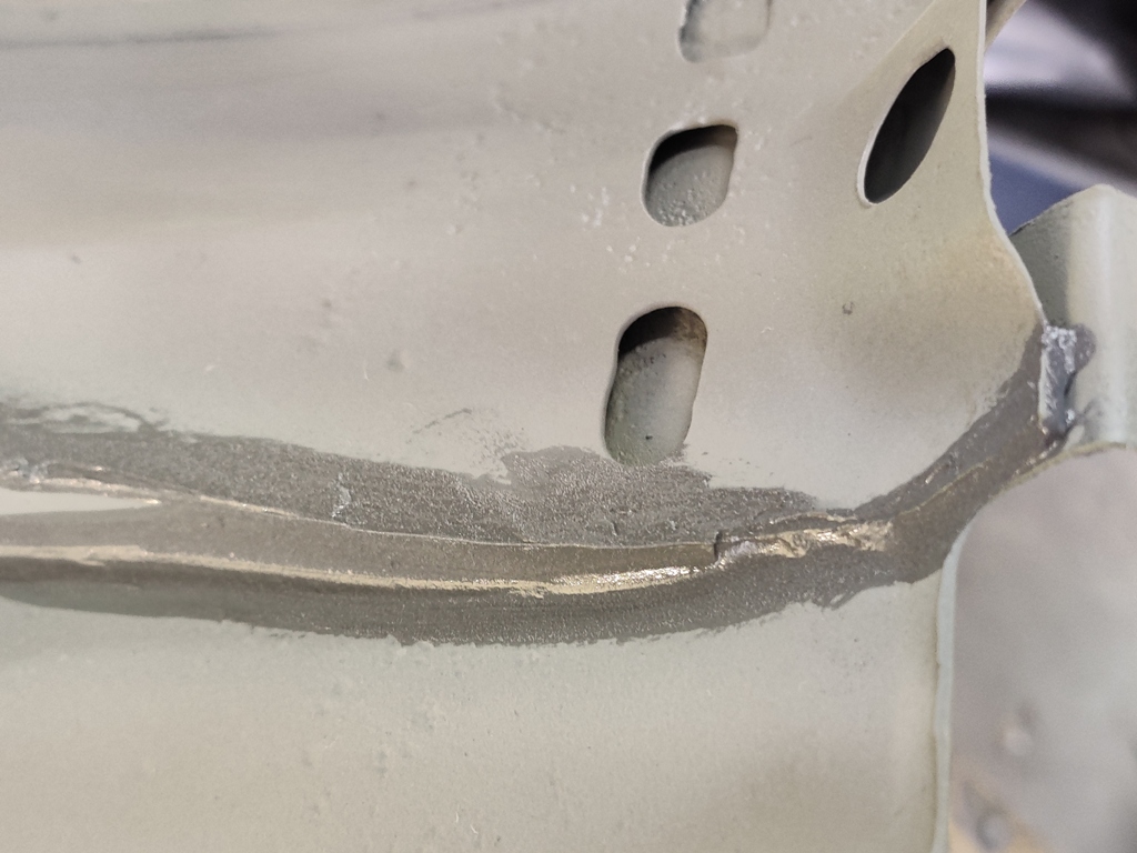
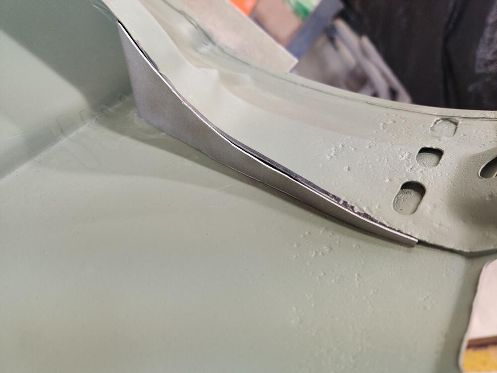
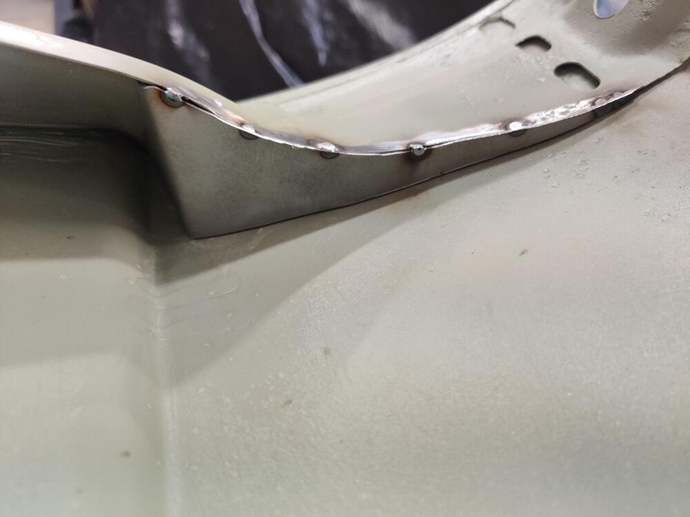
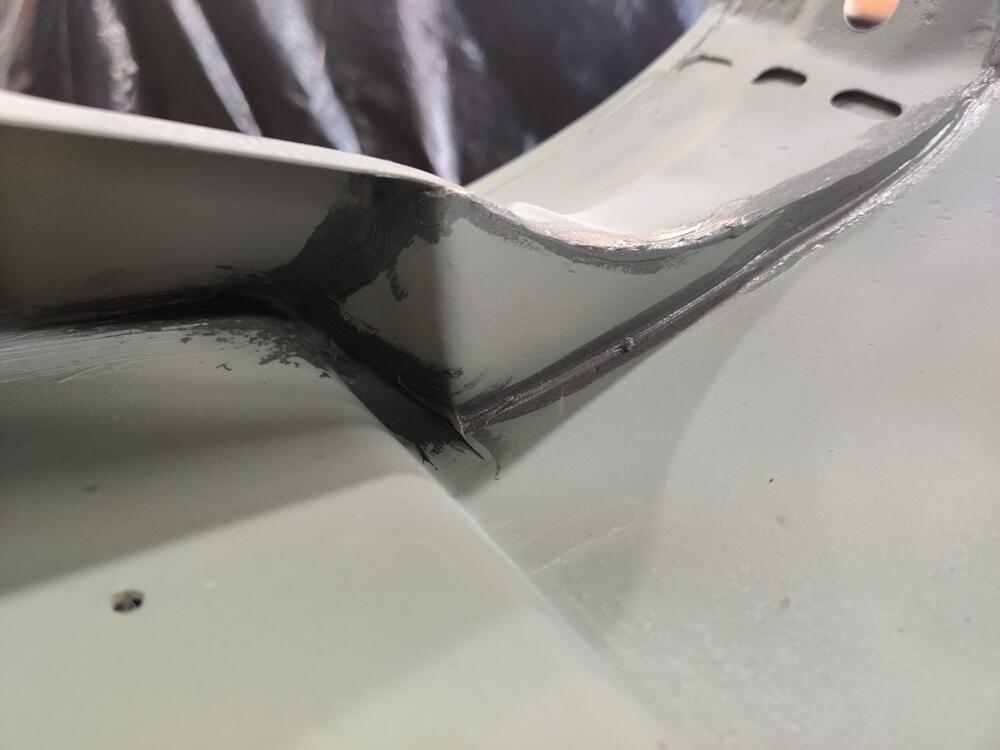
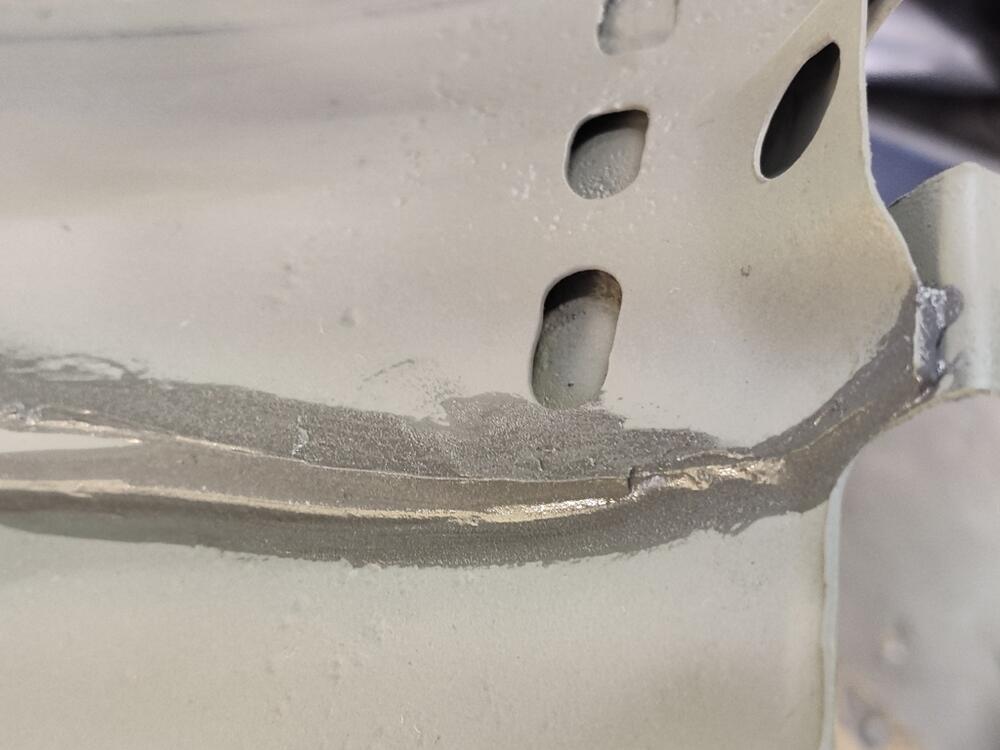
I was able to fabricate these for both fenders today. This metal piece is easy to fabricate as it only has one bend. I decided to tack weld it to the support instead of using pop rivets - thanks grannyknot for the suggestion. I did not tack it anywhere else though, as the body work is nearly finalized and I am not interested in deforming the outside surface of the fender. Hopefully, the addition of this piece does not cause a change in the shape of the panel when it is bolted in place. It might. And more time on bodywork will be the result if it did. After tacking, I used a hand-held belt sander to clean up the edge and then applied seam sealer. Now, any water coming inside the fender will run down the inside and be directed away from this corner by the shelf of this panel.


 1 point