Leaderboard
-
zKars
 Subscriber
 9Points3,769Posts
 -
26th-Z
Free Member6Points5,264Posts -
Tomcat
Free Member3Points44Posts -
Mark Maras
Free Member2Points3,719Posts


Popular Content
Showing content with the highest reputation on 08/17/2016 in Posts
-
Me thinks this is a speaker guard. Why a speaker may need a guard is another question...3 points
-
I don't know that they actually do. I just made that up. Glad you were entertained.2 points
-
I suspect there will be adopters of both solutions. Depends on what your skills and acess to tools and lock cylinders. Besides now i have to make and sell the little lock bracket plates Prize? I believe mentioned "points".. . Here ya go.
 2 points
 -
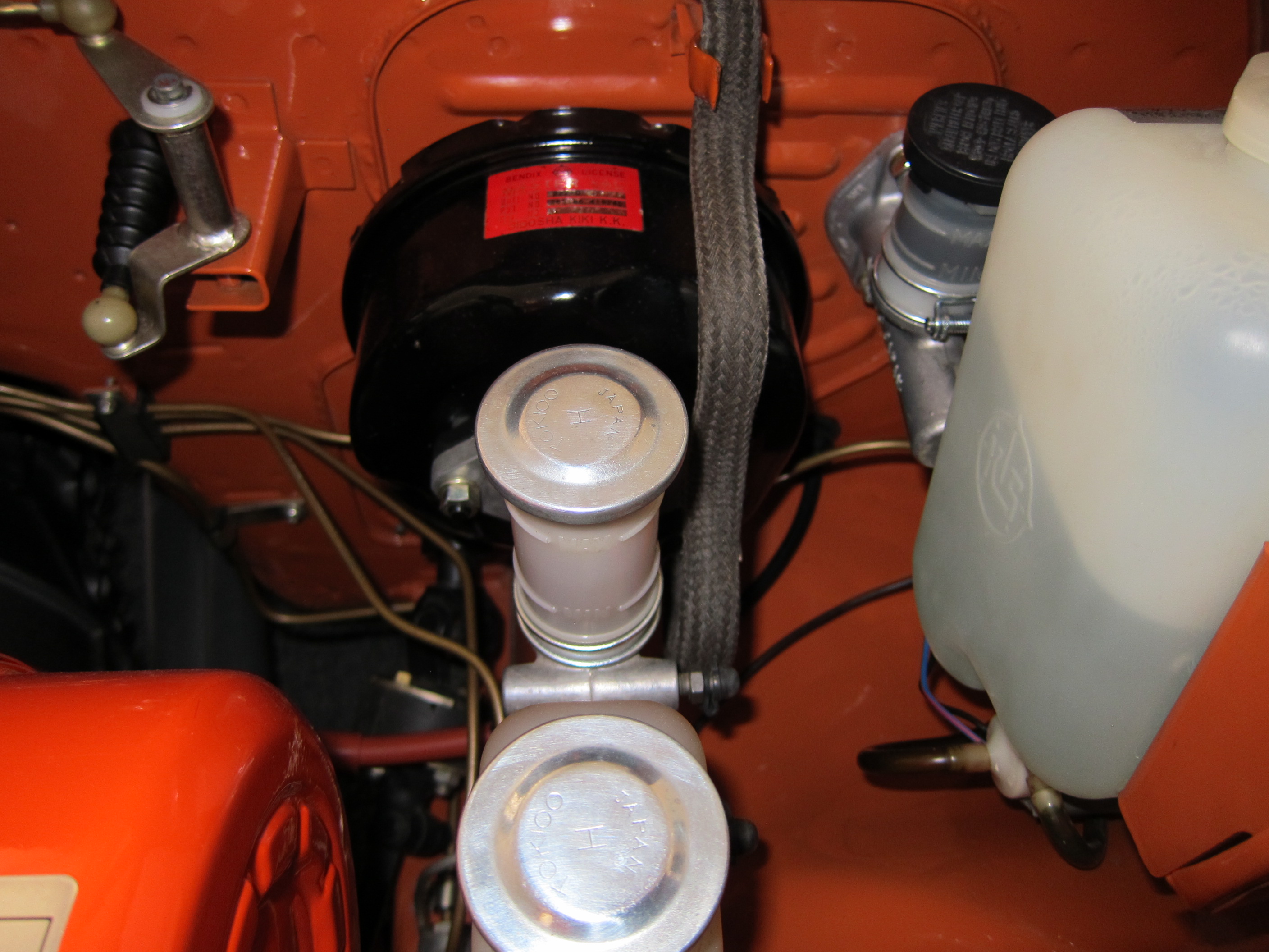
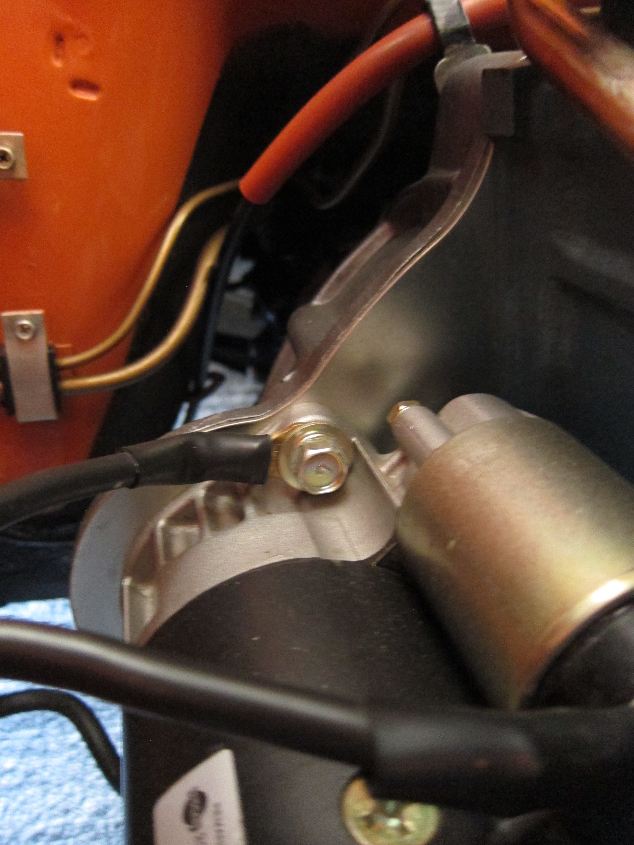
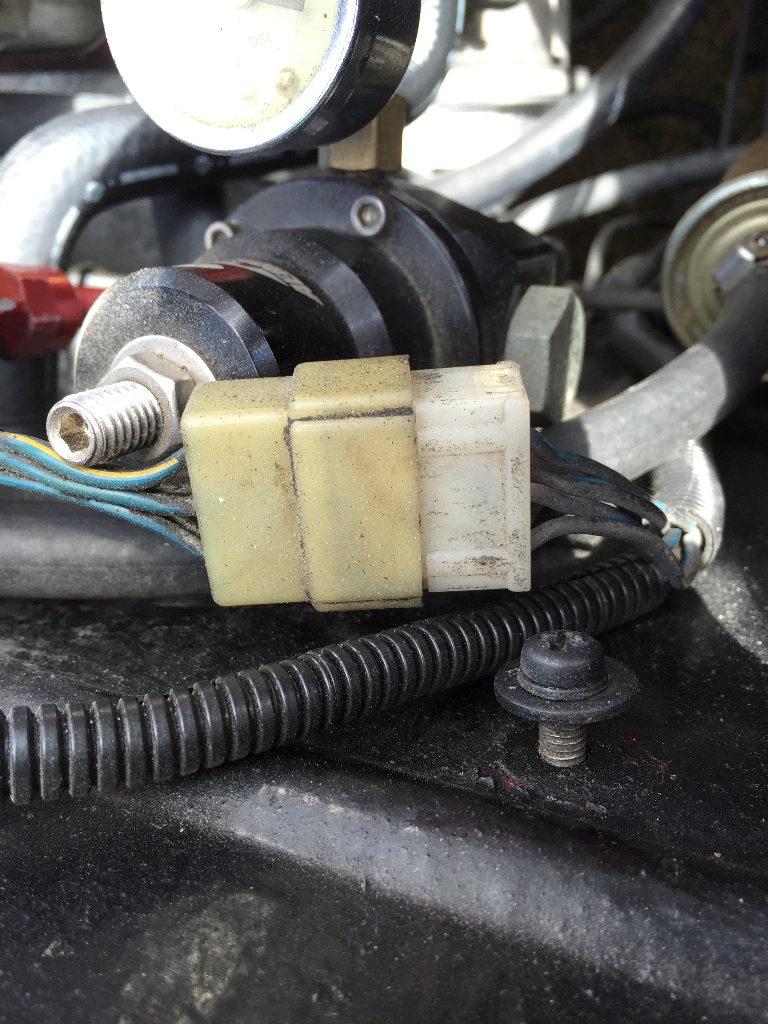
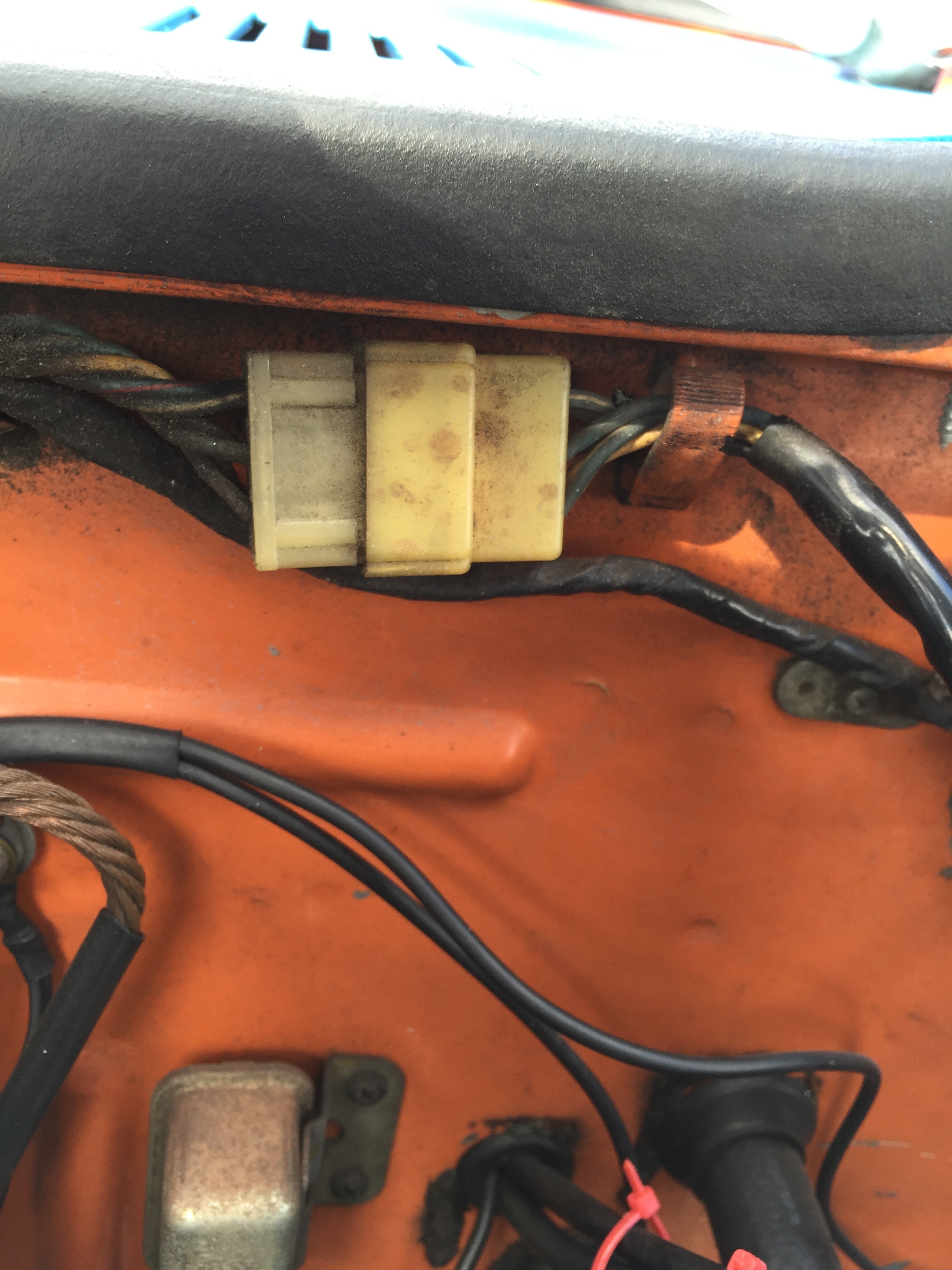
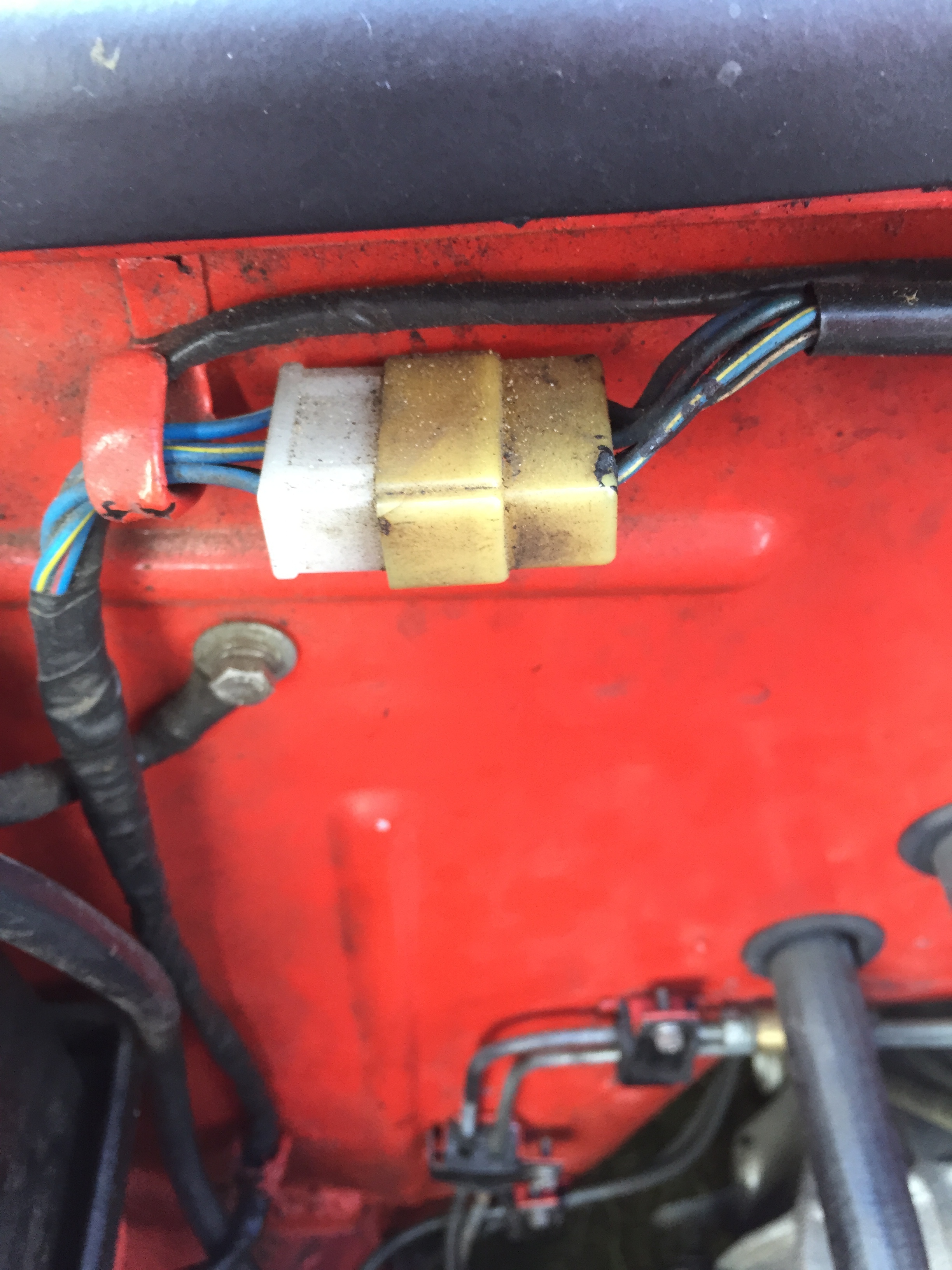
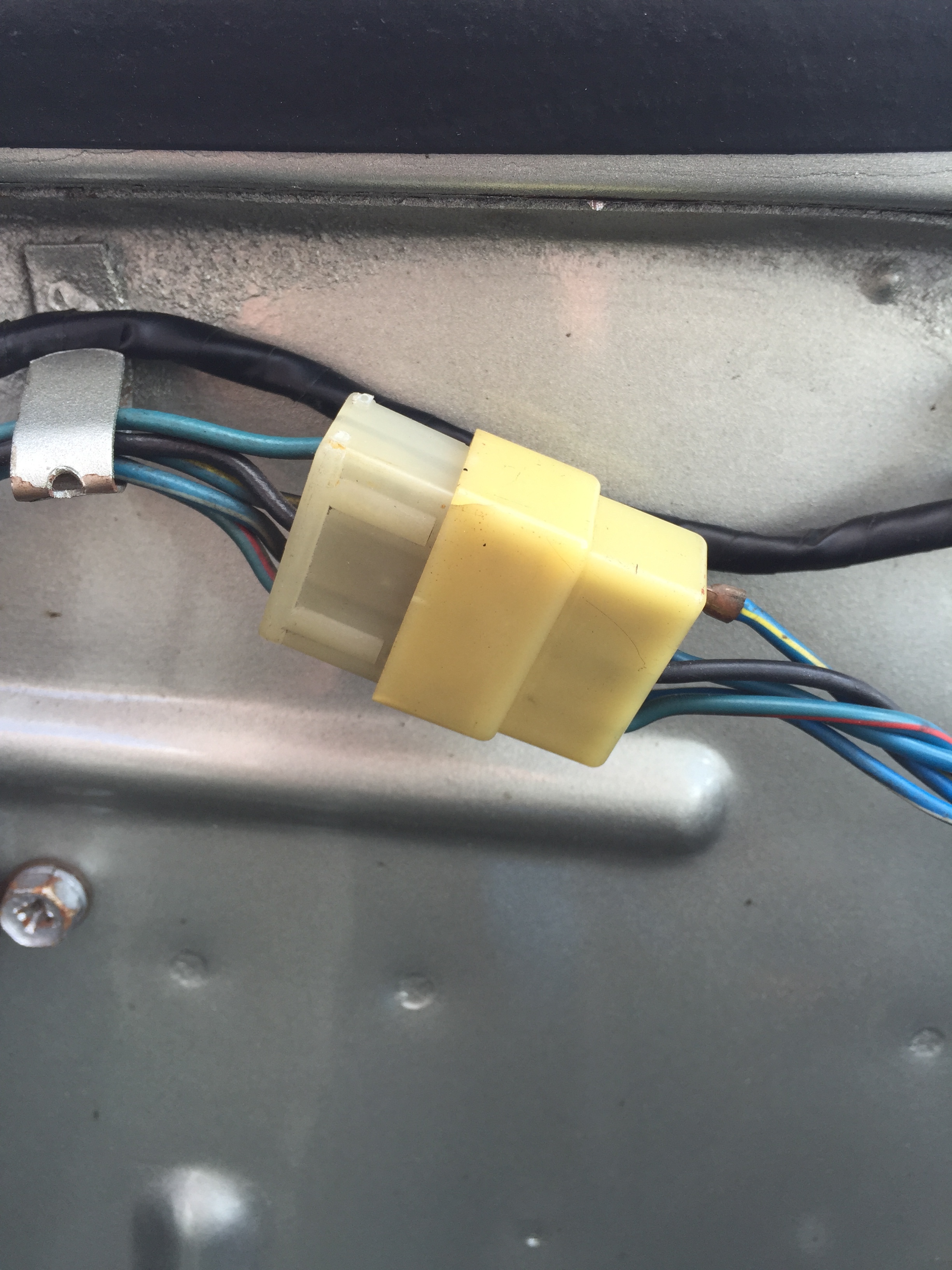
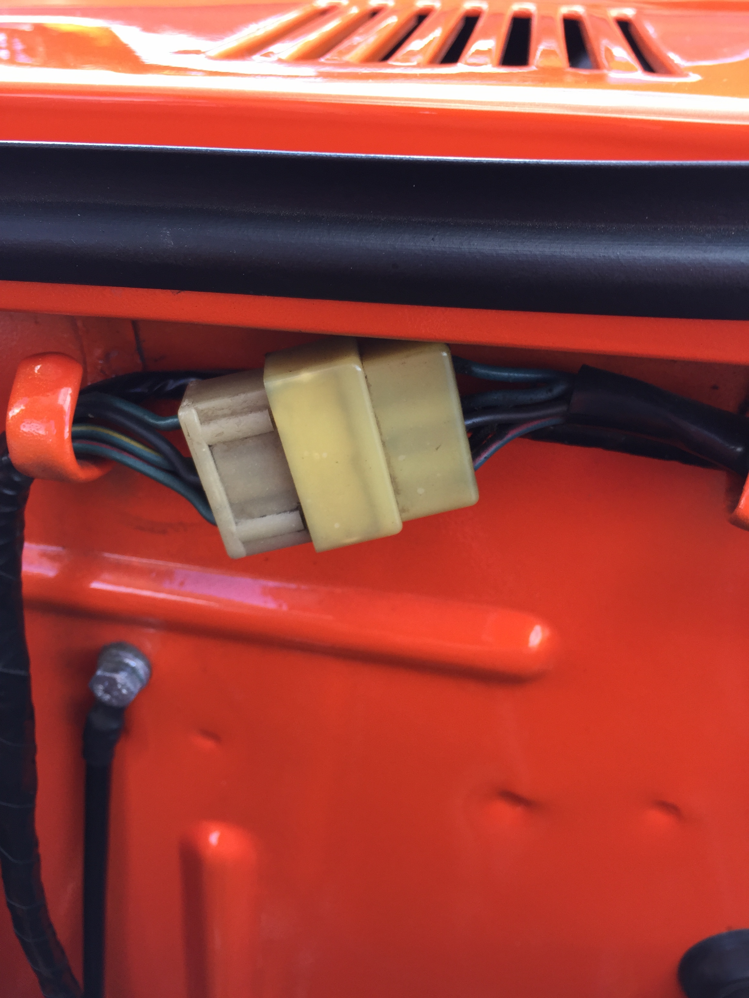
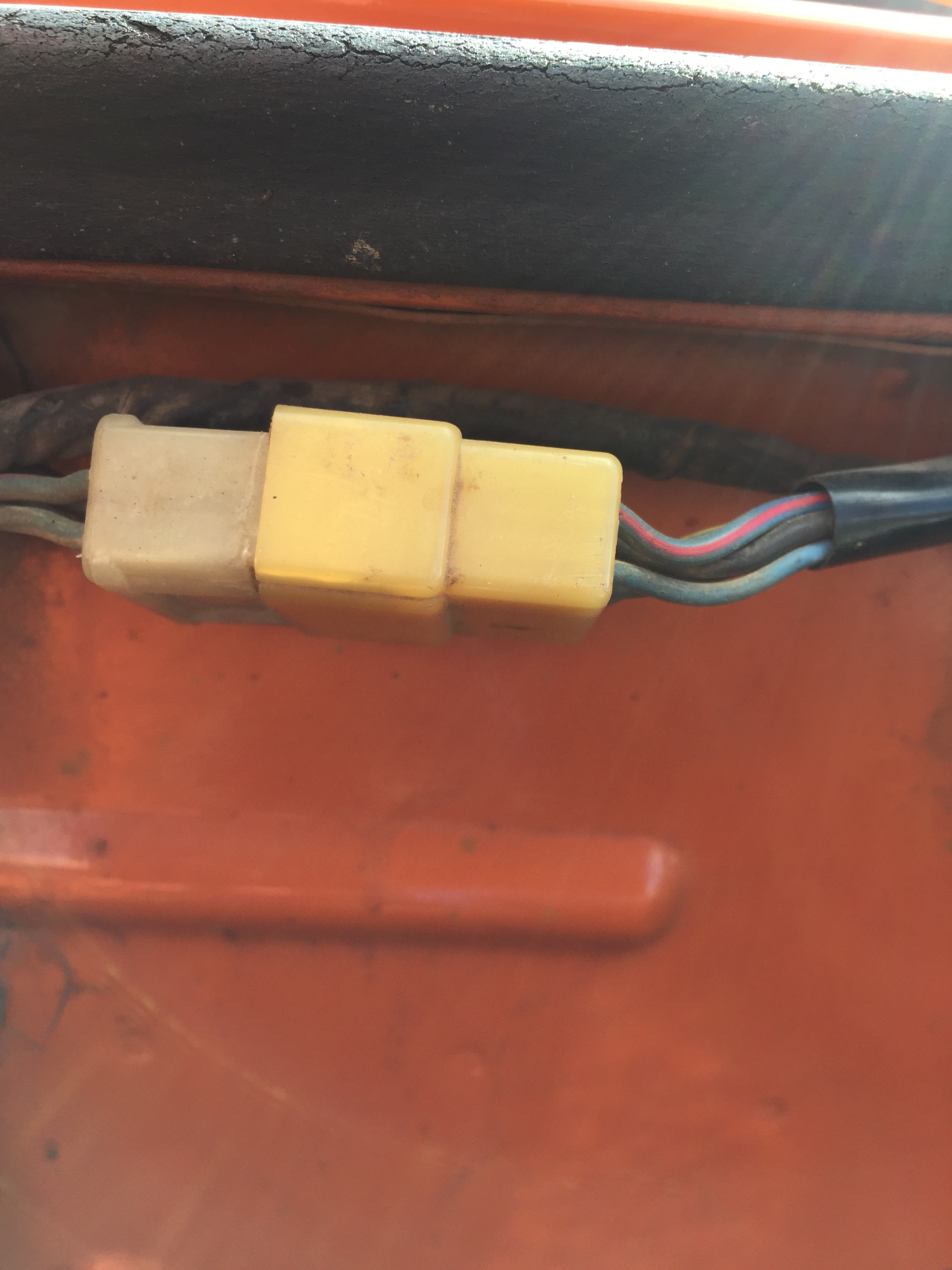
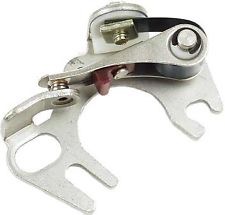
Niles Manufacturing provided automotive switches to Nissan. I don't recognize the piece. Perhaps if I knew where it came from on the car. Hitachi voltage regulator for the original "grapefruit style" alternator. Covered in undercoating. 40amp (45 amp?) capacity TL1Z-37 Oil pressure gauge sending unit. The original sending units had a bayonet plug fitting. This one is either aftermarket or later model type with the electrical fitting changed. Speaker cover (as required to deliver the proper base vibe. Commonly known in speaker techno circles as the back-plate acoustic reverberator bouncer designed for single speaker AM audio systems.)2 points
-
2 pointsSorry for not having been around for a while. Well my beloved 75 Z is sold and on her way to the South of France. A collector saw her for sale on E-Bay and we came to a satisfactory deal. I hated to see her go after all the blood(literally) sweat and tears plus a few screams of frustration that was put into her over the past 3 years. I have to thank lots of people on this site for assisting me in the rebuild, I could not have done it without your kind assistance all the responses to me sometimes repeated questions. Thank you all again and who knows, I may be back with another one in the future. Mike2 points
-
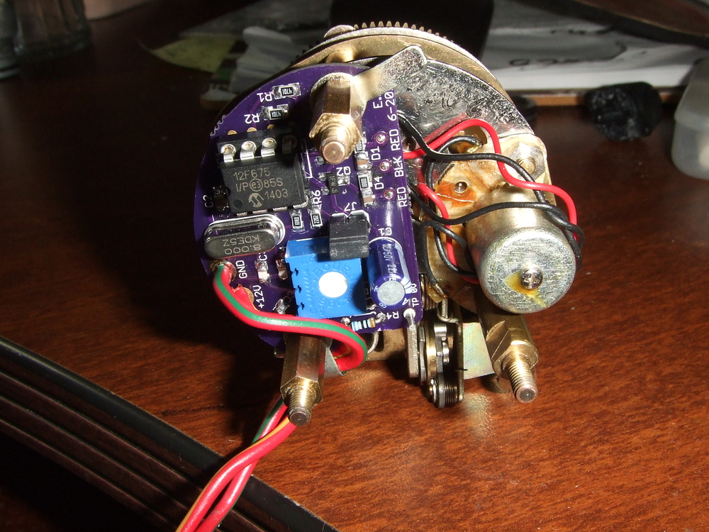
It’s been a lot of fun working with Greg on this. Though that code is somewhat old and it’s changed a bit. Also, it’s from back when the clock I had to test with had a broken tooth on one of its gears. I then installed Greg’s custom replacement gear and got the clock to work better (so I could take more reliable measurements). As it turns out, that little cylinder in the clock is what I think would be called a 10-pole PMSM (Permanent Magnet Synchronous Motor). I found the frequency it required was much closer to 50Hz with a half-cycle time of 10ms rather than the 44Hz (half-cycle time of 11.4ms) I was using when I wrote the above test code. I also found a duty cycle of about 80% worked well, so I stuck with that and got rid of the adjustment pot. This might not be of great interest to anyone, but I felt I had to mention the timing errors in that posted code in case anyone wanted to do any tinkering of their own. Eric2 points
-
2 pointsSocket head cap screws ... excellent idea ... wish I'd known that LAST weekend. To tighten the bolts on mine I took off both rear wheels, got a long flex-head ratchet on the top bolts with the handle pointed toward the gas tank, and reached through the fender wells to grab the handle. I was only able to turn the nut a single ratchet click or two at a time. To an outsider I'm sure it looked like I was artificially inseminating the car. I'm an EE too, but this Z sometimes makes me wish I was a mechanic/welder/bodyman/psychic instead.2 points
-
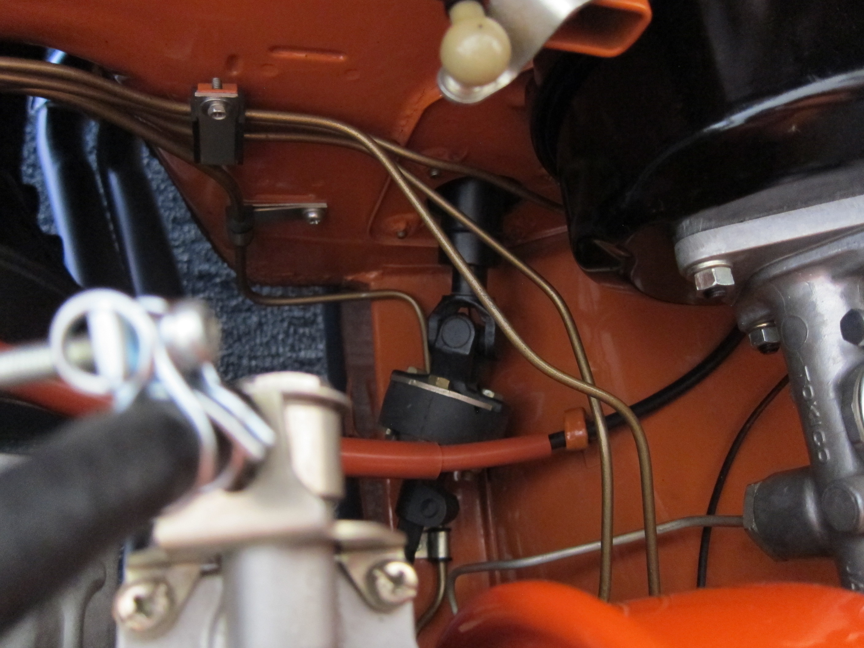
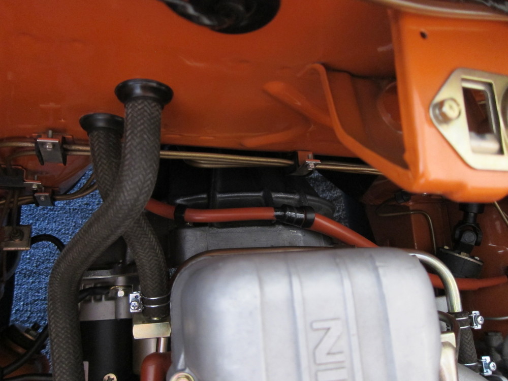
1 pointHere are the pictures from my 1/71 series 1 car. I am 100% cerain that this is the factory speedo cable routing. Dan


 1 point
 -
1 pointThanks guys, I was really asking about the materials and supplier but reading through @Hardway 's "how-to" he said he would go with Classic Datsun's covers in a do-over ... but you did save me having to post a second thread in a few weeks saying "So, I bought kits to redo my seats but how do you do it?" --Thomas p.s. I did search before asking, just not thoroughly ... I should have used "classic datsun" in quotes ... duhh.1 point
-
1 point
-
Let me say something here and try to help you out with your ideas about things. There is no such thing as "series 1, series 2", etc. That is American market nomenclature for differences between model years and an attempt to label Japanese production methods equitably with the American automotive manufacturer's methods we're familiar with. It just doesn't work that way. What you may call "prototype" was production at the time. Prototypes were not sold, exported, delivered, what ever. Certainly there were parts that came with the very early cars that were almost immediately superseded by something similar but really all you can say is; "oh look! This part is manufactured differently". There isn't any rhyme or reason to what part went on what car and you certainly can't attach a certain "up to serial number" label other than what appears in Nissan documentation. And even then you are going to find anomalies.1 point
-
These are tool storage compartment trim strips. Should be 4. Two per tool bin top edge to protect your precious hands as you reef the jack and stuff out of those cubbies. 249 doesn't have the storage cubby holes so put away for another day.1 point
-
Is this not the stock battery cover that goes under the top hold down bracket? We spotted a couple of these at ZCON.1 point
-
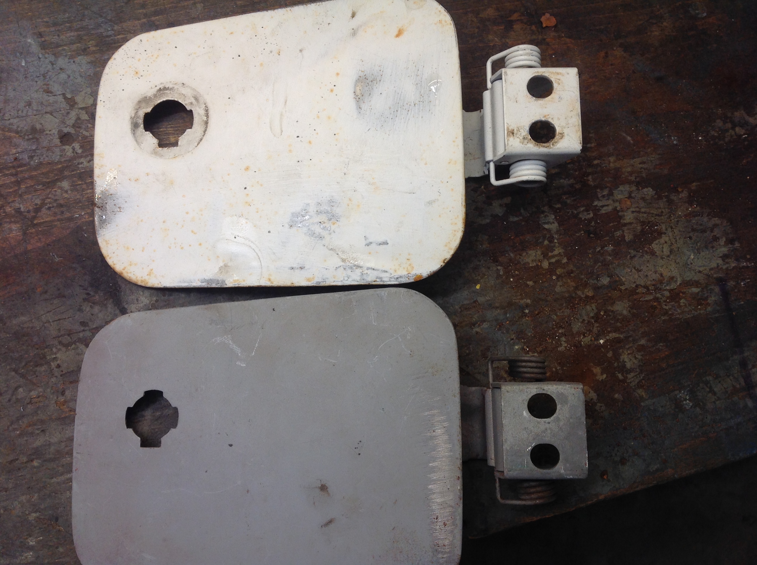
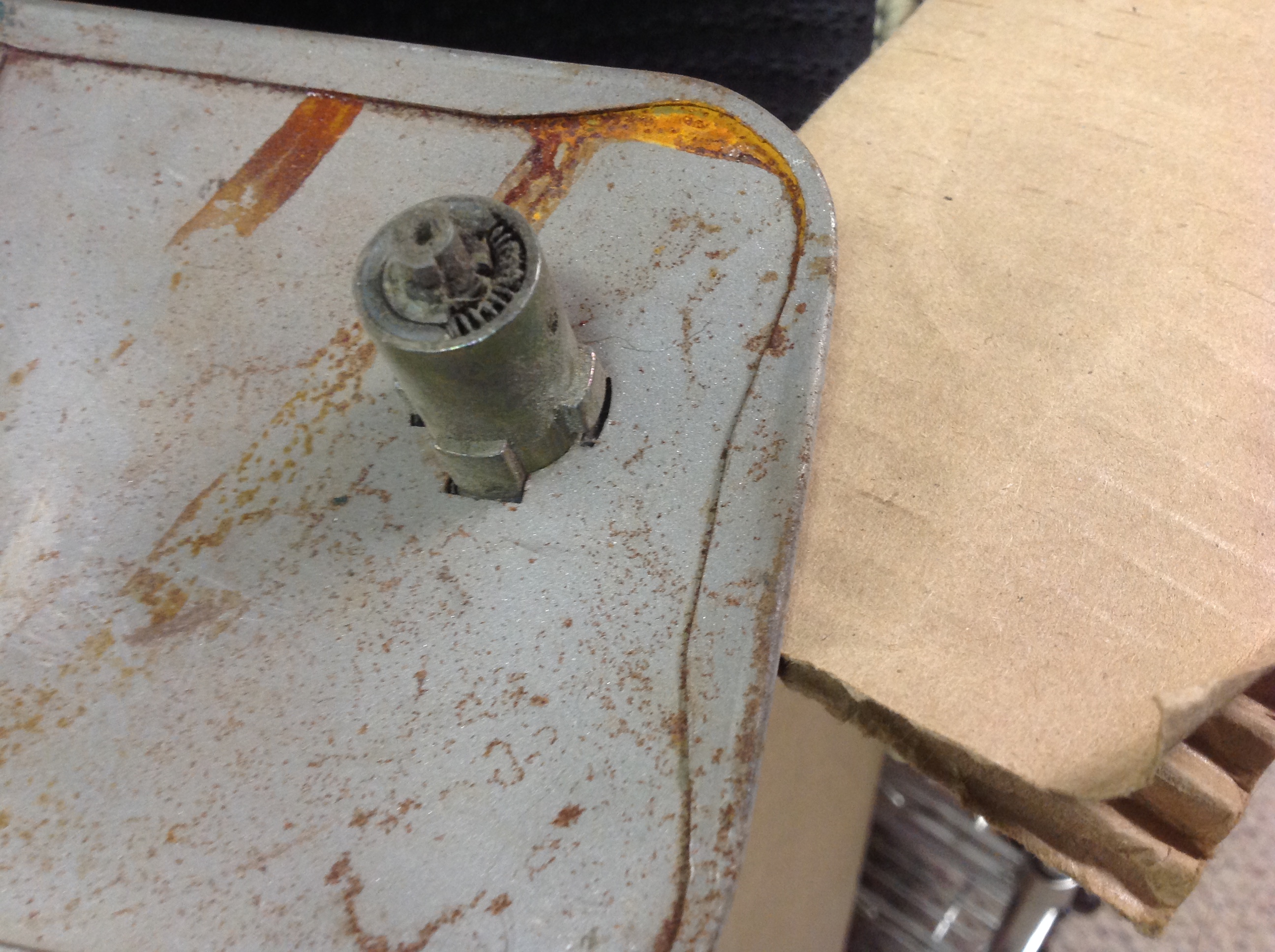
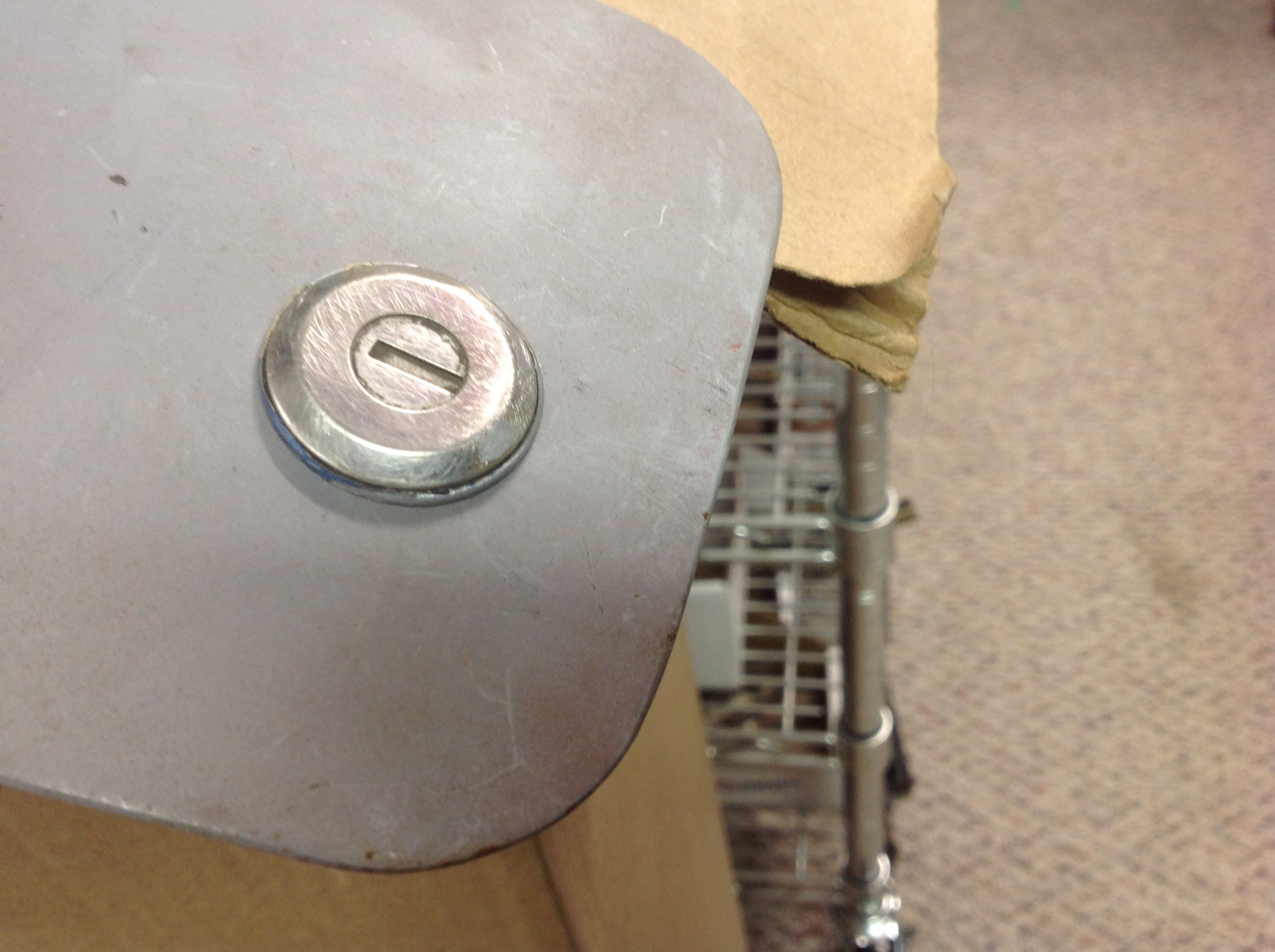
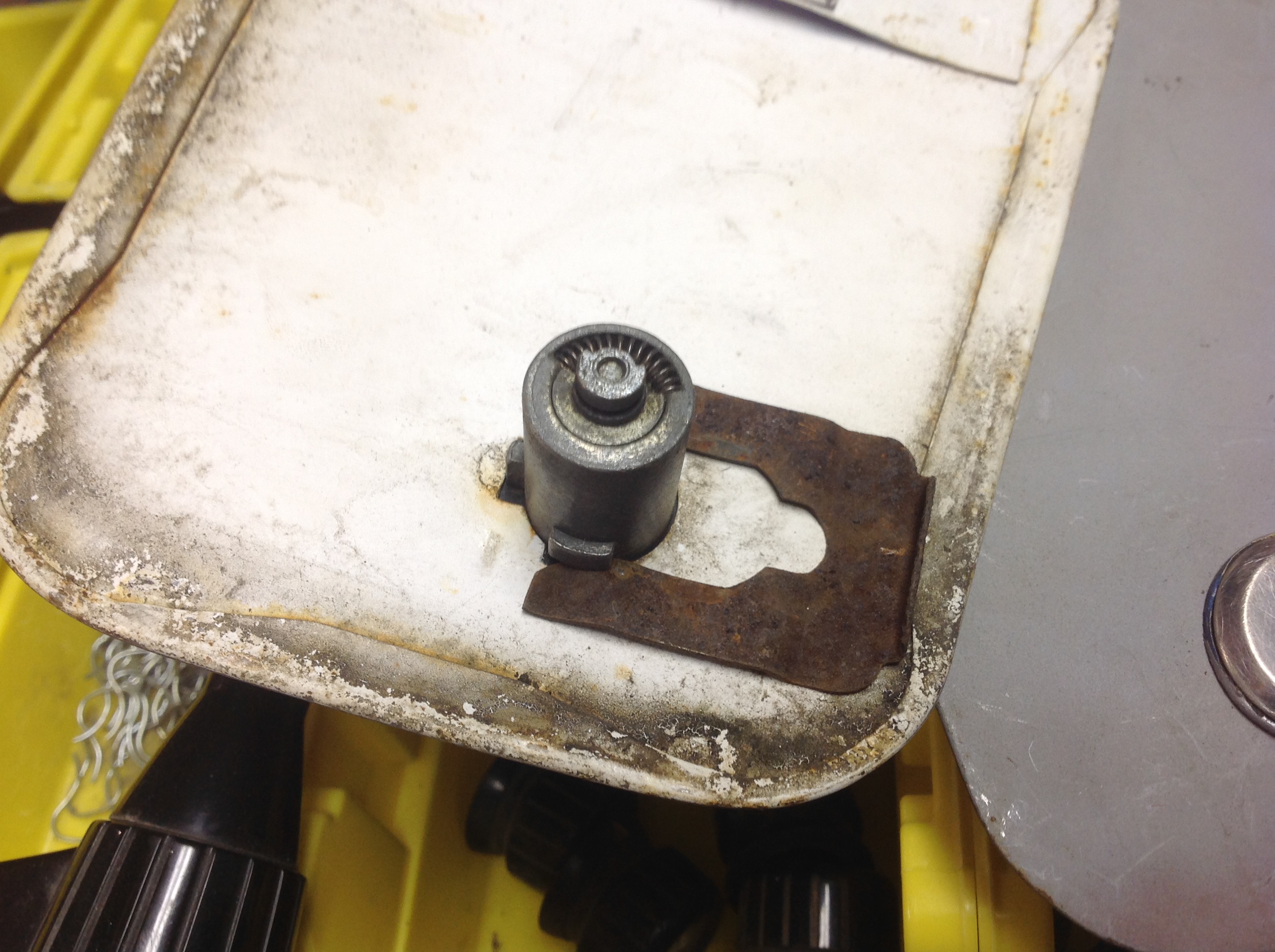
Velly Intellesting... (tell me where that came from and how said that way for extra bonus points...) The "stash" reveals not one but two different gas door with latch hole configurations. The three slot and the four slot. The good news here is that standard door cylinders slip right in there like they belong. Either three or four tab styles. Either can be positioned in any orientation. Standard lock cylinder retaining clips work just fine too. Now the only remaining issue, other than creating some rear brackets to fit on the end of the cylinders that will engage the body mounted loop, is that door cylinders may not have the correct "action". The key when inserted, can be turned left or right about 60-70 degrees, where the key cannot be removed of course. Is this enough to swing the rear mounted bracket up or down enough to clear the loop to allow the door to open? I envisioned that a gas cap lock cylinder would be rotate 90 and stay in either position, rather than the spring loaded auto-return action that a door cylinder provides. Anyway, I think this still would be a workable solution. All you need to do if you don't have a door with a hole is drill one in the right spot and file/dremel in some clearance slots.


 1 point
 -
1 point
-
I agree the "unknown plastic piece" is a speaker guard. They were used to protect speakers from dripping water damage when the speakers were installed in the door panel, or almost anywhere in an old Z.1 point
-
I've got one of these laying around...it was a guard for the driver-side only speaker.1 point
-
1 point
-
Red dot mirror. I thought the red dot was on the wide face, not the narrow. Seat belt hook, yep. Screws to the side of the seat with a chrome screw and transparent plastic washer. I don't recognize the wing nut.1 point
-
Update time. I've received the purple pcb oscillator and installed it. It's way smaller that it looks in the pictures. It took about 20 minutes to solder in the new board and bolt it in. I will be testing it with my other clocks to see how accurate it is. Right now i've had it running a couple hours and its keeping accurate time. It has built into it, reverse polarity protection for those of us that are electronically challenged, myself included. I've ordered a small amount of boards as I don't anticipate many people will need them. clock running with new purple oscillator Reverse engineering this clock and running it on 21'st century electronics was no small feat. Here is some of the C code that Eric wrote for the prototype and resides in the little IC chip. AWESOME work he does. __________________________________________________________________________________________________________________________________________________ #include <htc.h> #include <xc.h> //#include <float.h> // do I need this? #define _XTAL_FREQ 4000000 // Internal Oscillator... for now. Required // for __delay_ms function /* The configuration bits can be set in the IDE 'Configuration Bits' window, * or they can be set here. */ // PIC12F675 Configuration Bit Settings: /* CONFIG */ #pragma config FOSC = INTRCIO // Internal oscillator. #pragma config WDTE = OFF // Watchdog Timer disabled. #pragma config PWRTE = OFF // Power Up timer off. #pragma config MCLRE = OFF // MCLR pin disabled, I/O function of GP3. #pragma config BOREN = OFF // Brown-out detect off. #pragma config CP = OFF // Program memory code protection off. #pragma config CPD = OFF // Data memory code protection off. unsigned int pulse_width_count = 0; // Used to adjust pulse width. volatile unsigned int T_pot_setting; // Most sig 8-bits from pot ADC conversions. volatile unsigned int F_pot_setting; // Use all ten bits, so need 16-bit word. volatile char outputs; // bit0 for output 0 (GP0), bit1 for output 1 (GP1). volatile unsigned int analog_reading; // The 10-bit ADC result. /********************************* SETTING UP ************************************/ /*********************************************************************************/ void init_ports(void){ // Set input & output pins: GP2 (AN2) and GP4 (AN3) set as inputs for analog signal, // GP3 can only be input. TRISIO = 0b00011100; // Comparators off. CMCONbits.CM = 0b111; // Analog input register ANSEL set in setup_ADC() below. } //////////////////// void setup_osc(void){ ; // Nothing to do here. The oscillator is set above by setting the FOSC bits. // OSCCAL = 0x00; // Shouldn't be needed. } //////////////////////// void setup_timer1(void){ // Timer1 is 16-bit. It will count to 65535 before overflowing. // With a 4MHz internal clock (Fosc), the instruction clock operates at 1MHz: // (Fosc/4, so Tcyc = 1usec). // With a desired interrupt time of 11.43msec, we have 11430 instruction cycles, // which is under the 65535 cycles possible with Timer1. So using Timer1 should be // fine! T1CONbits.TMR1ON = 1; // bit 0 = 1: TMR1ON -> turn timer on. // bit 1 = 0: TMR1CS -> Clock source = Fosc/4. // bit 5,6 = 00: T1CKPS -> prescaler = 1:1 - no scaling. } ///////////////////// void setup_ADC(void){ // Pulse_Width is analog input on AN2. // Pulse_Frequency is analog input on AN3. // Set ADCON0 configuration bits: // ADFM = 1 : ADC result right justified as we will use all ten bits. Two most // sig bits in ADRESH, the eight least sig bits in ADRESL. // VCFG = 0 : ADC reference is Vdd pin.. for now. // <CHS1:CHS0> = 0b10 (2dec) to select AN2 input, (<CHS1:CHS0> = 0b11 3dec) for // AN3 input. // ADON = 1 : Turn on the ADC. ADCON0bits.ADFM = 1; // ADC result right-justified. ADCON0bits.CHS = 3; // Select AN3 for ADC for first conversion (freq). ADCON0bits.ADON = 1; // Turn on the ADC. // Set ANSEL configuration bits: // <ADCS2:ADCS0> = 101 for 4us TAD conversion time (datasheet recommended for 4MHz // clock). Analog input on AN2 (GP2) set for pulse time adjustment pot, and AN3 // (GP4) for frequency adjustment pot. ANSELbits.ADCS = 0b101; } /**************************** INTERRUPT SERVICE ROUTINE ***************************/ void setup_timer1_interrupt(void){ // Timer1 is a peripheral, so peripheral interrupts must be enabled // (and also global interrupts). TMR1IF = 0; // Clear Timer1 Interrupt Flag. PIE1 = 1; // Enable Timer1 Interrupt. PEIE = 1; // Enable Peripheral Interrupts. GIE = 1; // Enable Global Interrupts. } void interrupt ISR(void){ // Interrupt Service Routine // This interrupt it called at twice the motor (electrical) frequency. // Timer1 has timed out so we must aternate the GP0 and GP1 outputs. // The interrupt activates on overflow, so the starting value of the timer // must be determined to get the correct timer period. Calculations at end // of code. // Here we read and manipulate the last ADC result and initiate the next ADC // conversion. We will perform ADC on the two analog inputs alternately // (one for pulse frequency, and one to control the pulse width) // In reversing the pin polarity, the pins themselves are not reversed as they // might both be 0 (as the expiration of pulse_width_count will set both outputs // to zero). So 'outputs' records the last setting of output pins, and it is // 'outputs' that is reversed. This is then copied to the GPIO pin register. TMR1 = (0xDC00 - F_pot_setting); // Reset TMR1. outputs = outputs^0b00000011 ; // XOR - reverse outputs for GP0 and GP1. GPIO = outputs; // Assign 'outputs' to actual output pins. // Alternately update the Frequency setting (F_pot_setting) and pulse width // (T_pot_setting). if ((outputs & 0x01) != 0){ // Set pulse width. analog_reading = ADRESL + (ADRESH * 256); // Change 10-bit value to 8-bit T_pot_setting = (analog_reading >> 2); // value (max 255). ADCON0bits.CHS = 3; // Change A/D channel to measure Frequency pot // next time around. __delay_us(50); // Delay after channel swap, avoids cross-talk. } else{ // Set pulse frequency. analog_reading = ADRESL + (ADRESH *256); F_pot_setting = (analog_reading << 1); // Mult by 2 to scale to 0x7FE. ADCON0bits.CHS = 2; // Change A/D channel to measure pulse width pot // next time around. __delay_us(50); // Delay after channel swap, avoids cross-talk. } ADCON0bits.GO_DONE = 1; // Start next A/D conversion. pulse_width_count = 0; // Reset counter for pulse width. // GPIO5 = 1; // Turn on LED at GP5 - program running. TMR1IF = 0; // Reset Timer1 overflow interrupt flag. return; } /********************************** MAIN PROGRAM **********************************/ /**********************************************************************************/ void main() { setup_osc(); init_ports(); setup_timer1(); setup_timer1_interrupt(); setup_ADC(); outputs = 0b00000001; // Initialise output pulses variable with pulse // at GP0. GPIO = outputs; // Write to GPIO register. // Turn on LED at output GP5 - program running. while(1){ pulse_width_count++; // Delay chosen so that that 255 (0xFF) __delay_us(28); // increments take up the full 11.4 millsec. if (pulse_width_count > T_pot_setting){ GPIO = GPIO & 0b11111100; // Turn off outputs. GPIO5 = 1; // debug - turn on LED pulse_width_count = 0; // Reset so we don't keep coming back. } // if } // while } // main /* Determining the Timer1 starting value for interrupt for clock frequency: * * The clock I tested needs the outputs to be alternated every 11.43 millisec * for the clock to operate at about the right speed. * The microcontrller clock speed (Fosc) is set to 4MHz in the config parameters * at the start of the program. Timer1 increments with each instruction cycle which * is equal to Fosc/4 = 1MHz, so it increments at 1 microsec intervals. For 11.43 * millisec, the clock increments 11430 times. As the timer interrupts at overflow, * then the timer must start at 65535 (0xFFFF) minus the 11430. * 65535 - 11430 = 54105 (0xD359) approx. * The result from the A/D converter is 10-bit, i.e. 0-1023 (0x00 - 0x3FF). * This permits an adjustment time of about 1 millisec. If I want an adjustment * time of +/- 1 millisec (2 millisec) then I will double the A/D conversion result. * So the timer starting point will have to be about 0xD539 + 0x3FF, so that up * to 2 * 0x3FF can be subtracted from it. So starting point will be about 0xD938. * This is approximate as there will be some latencies in processing the code, etc * The final value will be higher and determined experimentally. So we should * have a range of about 9.4 millisec to 11.4 millisec with the 'correct' * 10.4 millisec setting when the control pot is set to the middle position. * * Determining pulse width: * * The output of the pulse width pot is saved as an 8-bit value: 0xFF (255 decimal). * At lowest frequency, the pulse width above will be up to 11.4 millisec, so we * need the pulse width counter to increment at 45 microsec at a time (45us * 255 * = 11.5 ms. An added delay of 28 microsec resulted in desired increment delays . * */
 1 point
 -
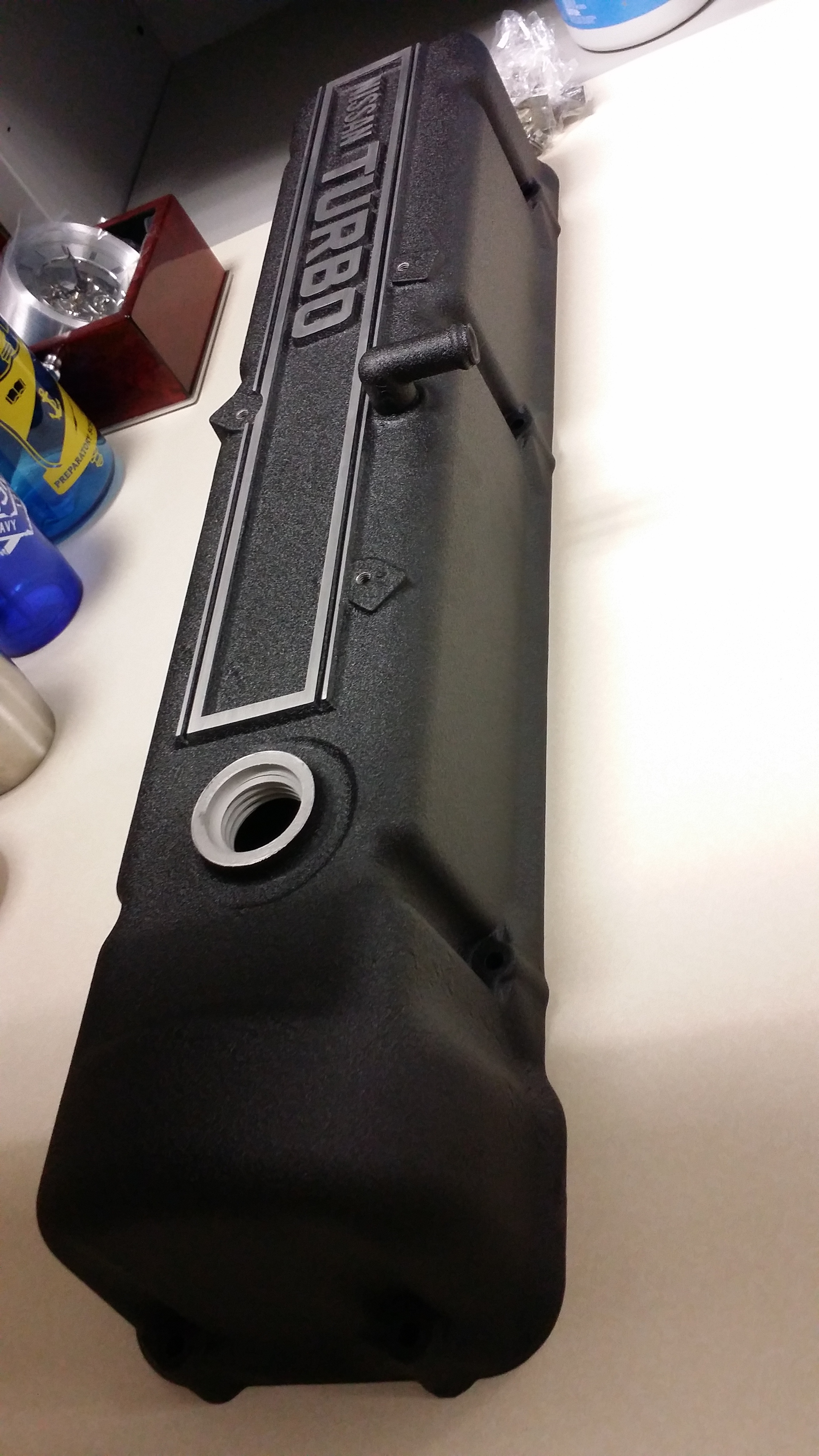
1 pointOrdered a an ATI pulley. In other news, the valve cover came back from 'the guy at work'. #beautiful.
 1 point
 -
Curious event yesterday. I was asked by my paint/body man to show my 280Z to a "friend" of his. I accepted and they showed up at my house at 3pm. The "friend" was Slick Humphries of the Discovery Channel's "Highway to Sell" series and owner of Slick's Garage. He's been a s30 fan forever (turns out his first car was 260Z and owns a similar car at this time) and wants to feature a Z project on his show. My 280Z is already "done" but he would like to use it on the show nonetheless. He mentioned what all of us already know: classic lines, iconic Japanese car, reliability, relatively low cost to own and restore, etc. and emphasized that interest for our cars is peaking and he wants to run that wave. Let's see if anything comes out of this and I'll keep you guys posted.
 1 point
 -
I don't recognize them as a Z part. Never seen wing nuts like them either. Could it have been some sort of flange nut before the distortion? The bends don't look uniform at all. What is the small round? protrusion on the left pic, left side in the middle?1 point
-
ZH, your metal strap design does everything the R/T mount does but is simpler, easier to install and lighter, thinking of going into production?1 point
-
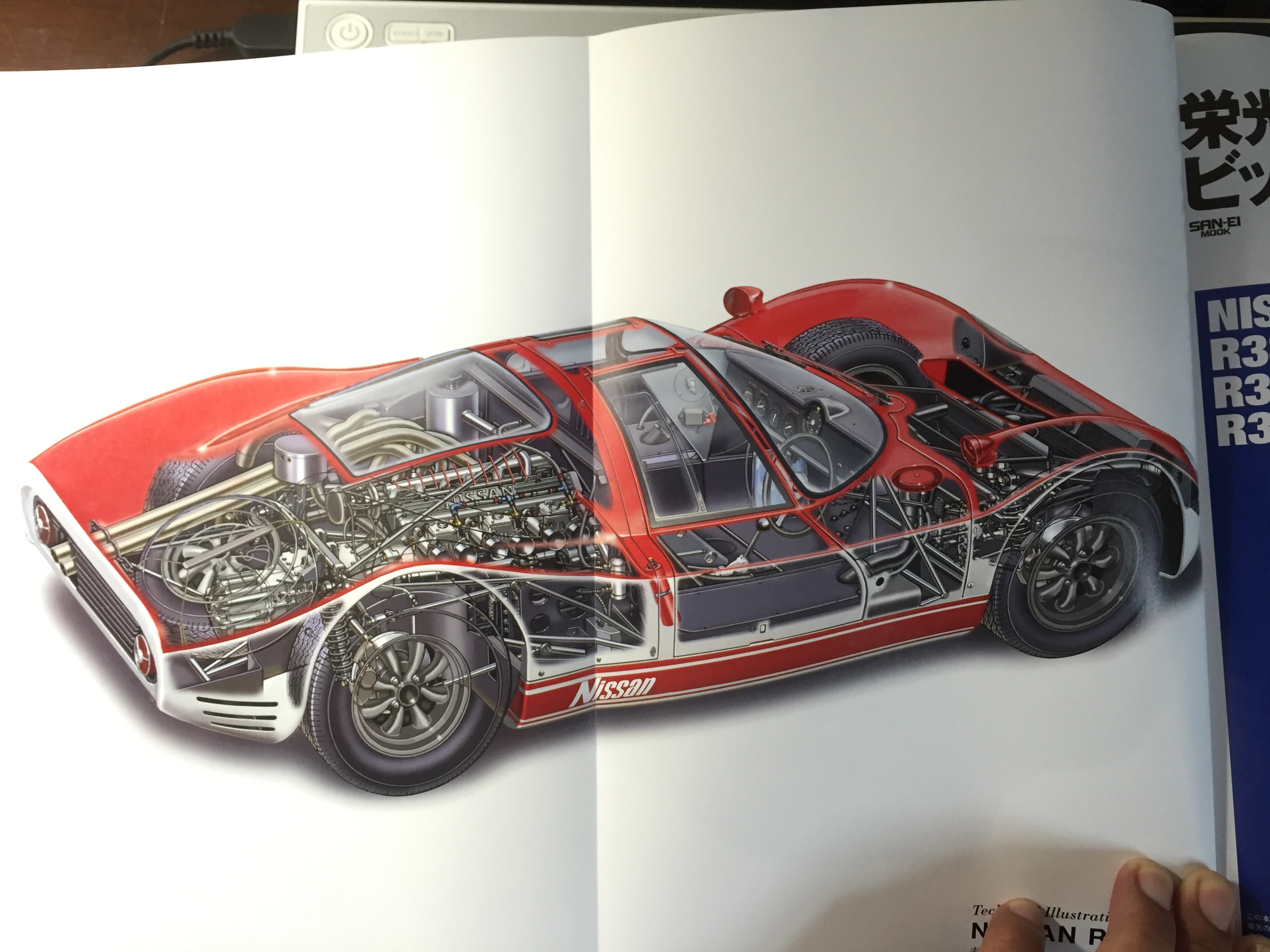
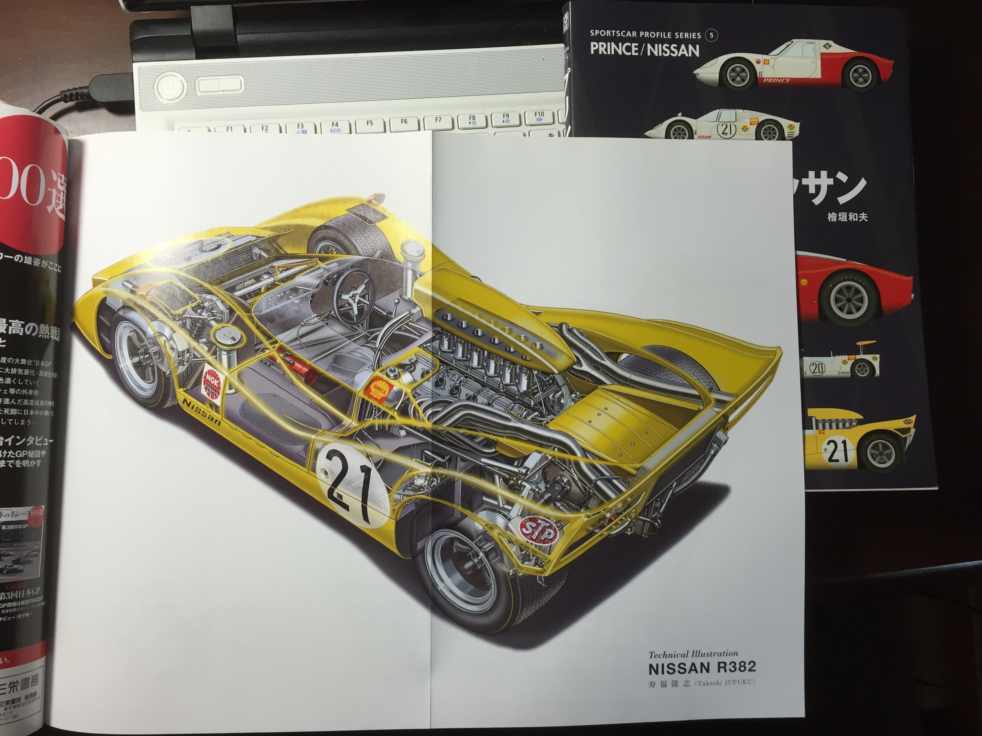
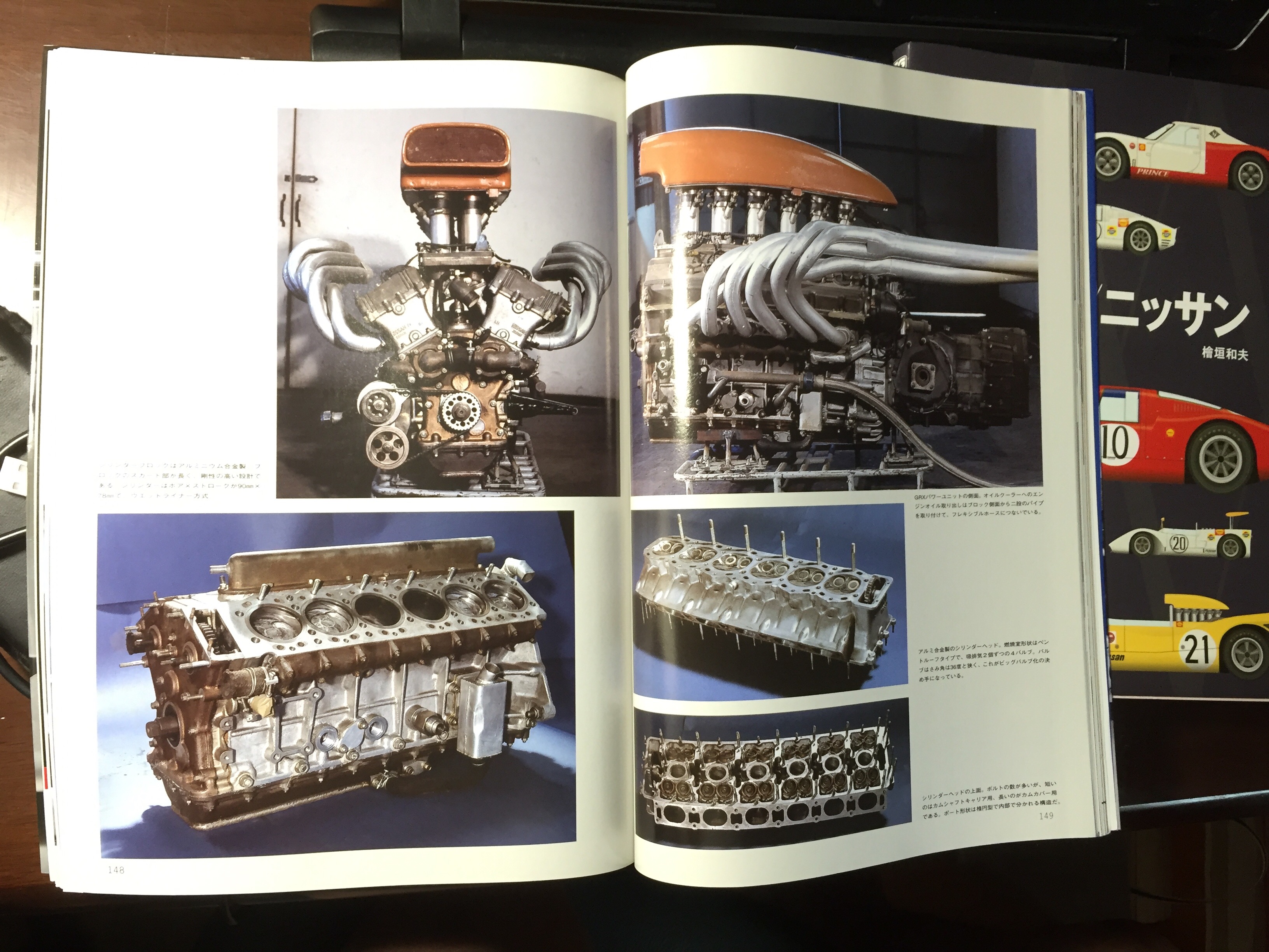
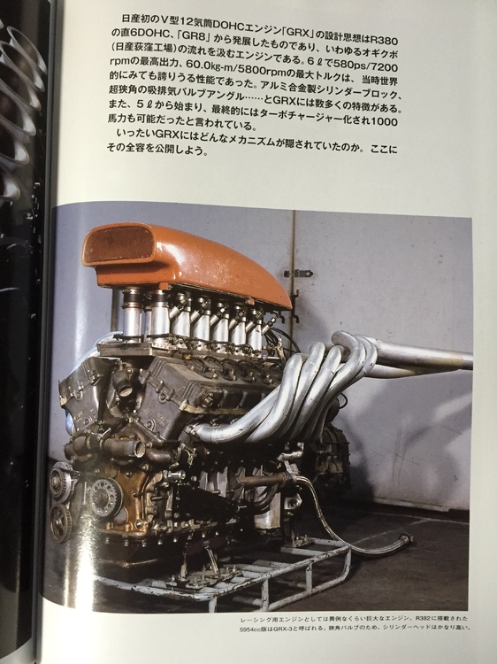
1 pointThanks Chris ! I really love R380-A ll, also R382 is my hero. On 10th October 1969, The R382 won the Japan Grand-prix .While Nissan Shatai was making 52 export 240Zs in October, your 26th & 27th could be stayed a bit longer in a assembly line because workers took National holiday and watched Japan Grand-prix ! (1964 Tokyo Olympic was on 10th Oct, after that the day became a national holiday) . The GRX (6000cc 580ps/7200rpm 60kg-m/5800rpm) was terrific, looks like two S20s were combined together. Kats


 1 point
 -
1 pointNot all of the items you listed are unique to the "series 1" cars. My car (4/71 build) is an early example of what some people in the U.S. call a "series 2" and it has, or originally had several of those items: E31 head Series A transmission 4-screw SU carbs. Dash mounted hazard switch Unused depression above the hazard switch. A lot of those things you list are common to all of the pre-73 cars. (or perhaps even to all of the 240s)1 point