


All Activity
- Today
-
 Keep up the good work Rob. You are primarily the member that keeps the history/photos that bring back memories and the passion to which we loved and fell in love with for the love of these cars. I applaud you for your efforts. I hope others will chime in. Merry Christmas My Friend. John
 -
 Rally!
-
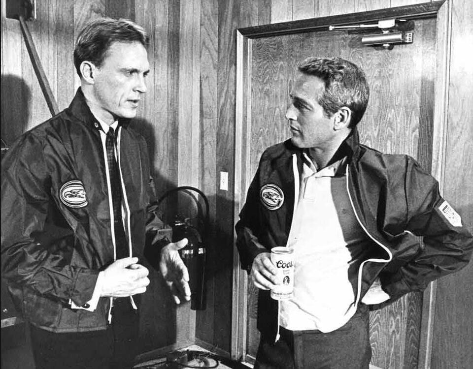
Proof he’d drink something other than the sponsors beer…
-
 I had seen the Toyota on BaT and was going to post it up... Many of the cars from this era are too small for me. It one reason I probably won't ever have a Ferrari. The ones I can afford are too small. The 240Z is nice and roomy an anomaly of the day it seems
 -
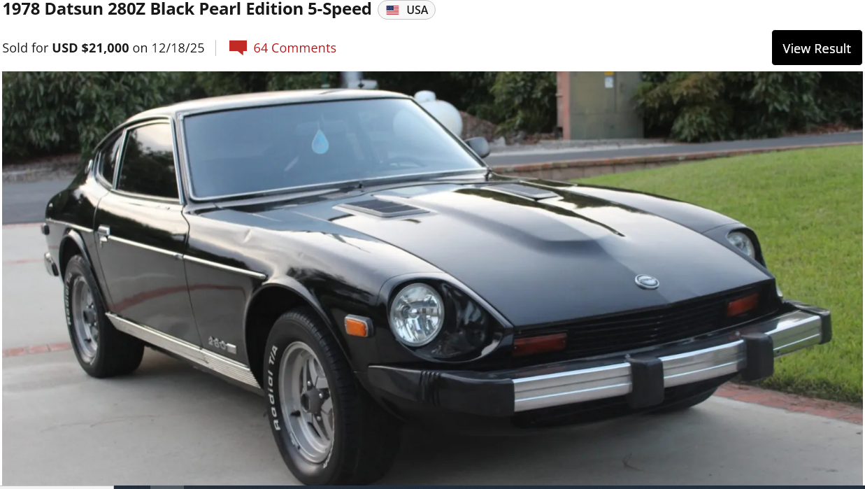
 Here's another 280Z in the 20's. Not terrible. https://bringatrailer.com/listing/1978-datsun-280z-181/
- Yesterday
-
 Garage 44 and BRING A TRAILER will know exactly what is happening, and when. So if you really want to know I suggest you contact them direct(ly). While you have their attention you might like to suggest a start date and time that fits your busy diary schedule. Clearly you're just gagging to make a bid.
 -

-
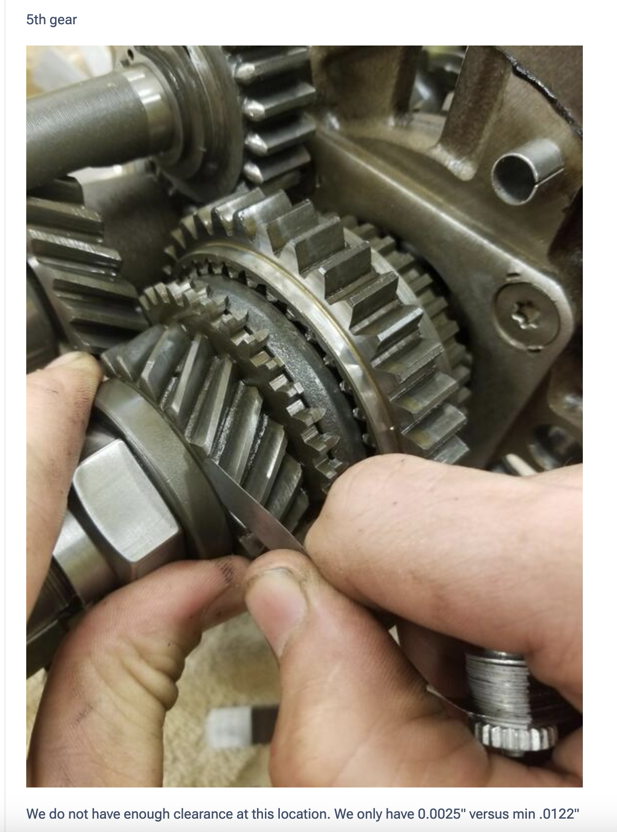
If you check the length of part 54, you will find that it is shorter than 48. That is the root of the problem. As a result, thrust washer 64 is clamping fifth gear 48 instead of the inner bearing bush 54. The previous owner may have encountered this issue and attempted to compensate by loosening the nut😪 To resolve this properly, you will need to shim 54 until the specified end-play tolerance for 48 is achieved. You can determine the required shim thickness by measuring with Plastigage and then adding the specified end play to determine the correct shim thickness. Once you understand how the parts interact, this becomes a straightforward fix.
-
" I assume that the no. 64 is to tight to 54 and thats the reason why there is basically no gap between 55 and 64 and therefore the gear 48 is blocked" The photos and video of the loose nut make the situation much clearer now. No. 64 should be tightened firmly against 54. The problem started when the nut became loose, allowing 54 to spin with the gear and wear against the thrust washer (64). Everything being done now is essentially compensating for the wear on the inner ring (54). If 54 is loose, it will also vibrate, which is most likely what is causing it to jump out of gear.
-
-

-
Coming up on two months. Quite a few days more than a few. Anybody know what's happening? It's all part of the story.

-
 Sorry, I got the positions reversed. For many years I lived in Laurel, MD. Laurel is on the original B&O line between DC and Baltimore. This is the line along which Morse laid the first telegraph line. Laurel had a 4-5 block shopping district on the appropriately named "Main St". I came out of a Main St. business in about 1974 to see white 2000GT in front of one of the businesses. I guess it was an almost daily driver. Imagine.
 -
 "Rock the Stock"
 -
 Has anyone seen the Lexus tv commercial where a woman is parallel parking her SUV from her seat in a restaurant? Some sort of self parking system. Anyway, The car in front of her SUV is the contemporary Toyota supercar , can't remember the name. I can certainly remember the name of the car behind hers - 2000GT!
That would apply to most ergonomics. Designers, engineers, architects and even shoe makers have to work within reasonable percentiles. Anybody outside the norms is just going to have to cope with what nature gave them. A little late for April 1st. I'l cite Karl Benz, Johan Sebastian Bach, Johannes Gutenberg and Milli Vanilli as five Germans who - like Albrecht Goertz - are not responsible for a single curve or line on the S30-series Z. "Stolen"? Meh. Language of fools.
Has anyone seen the Lexus tv commercial where a woman is parallel parking her SUV from her seat in a restaurant? Some sort of self parking system. Anyway, The car in front of her SUV is the contemporary Toyota supercar , can't remember the name. I can certainly remember the name of the car behind hers - 2000GT!
That would apply to most ergonomics. Designers, engineers, architects and even shoe makers have to work within reasonable percentiles. Anybody outside the norms is just going to have to cope with what nature gave them. A little late for April 1st. I'l cite Karl Benz, Johan Sebastian Bach, Johannes Gutenberg and Milli Vanilli as five Germans who - like Albrecht Goertz - are not responsible for a single curve or line on the S30-series Z. "Stolen"? Meh. Language of fools. I don't agree.. far from it! Try to go sit behind the wheel when your 195 Cm!! ... or 6'6". You CAN'T ! And those lights on the front look like 2 giant ugly eyes, the 240z is MUCH better designed. (And i stick with this: those 240z front lights were a idea of a german! that a Japanese guy took over.. better stolen a nice one than design a bad one myself he must have thought.)
Why then replace it? I drove a 240z that had it's original distributor for 54 years!! Why do people assume it will be bad??? I sold it and it was still in there and will be for a long long time! (maintenance IS KEY HERE !!!) In 25 years i used 2 sets of contacts.. and heard A LOT of complaints about elektronic ignitions that where A LOT worse than the ORIGINAL ignition !!! So, clean up that old fart and use it and maintain it, there must be some instructions in the serv.man how to check if your ign. equipment is good! And don't start about flamethrowers and 123ignition and all those other junk compettitors that say theire ignition is the best, the best is a original one. (That has been maintained properly!)
I don't agree.. far from it! Try to go sit behind the wheel when your 195 Cm!! ... or 6'6". You CAN'T ! And those lights on the front look like 2 giant ugly eyes, the 240z is MUCH better designed. (And i stick with this: those 240z front lights were a idea of a german! that a Japanese guy took over.. better stolen a nice one than design a bad one myself he must have thought.)
Why then replace it? I drove a 240z that had it's original distributor for 54 years!! Why do people assume it will be bad??? I sold it and it was still in there and will be for a long long time! (maintenance IS KEY HERE !!!) In 25 years i used 2 sets of contacts.. and heard A LOT of complaints about elektronic ignitions that where A LOT worse than the ORIGINAL ignition !!! So, clean up that old fart and use it and maintain it, there must be some instructions in the serv.man how to check if your ign. equipment is good! And don't start about flamethrowers and 123ignition and all those other junk compettitors that say theire ignition is the best, the best is a original one. (That has been maintained properly!) Just wow. The most beautiful car ever made.
- Last week
 The next best thing to a 240-Z. Bring a TrailerBobby Rahal's 1967 Toyota 2000GTBid for the chance to own a Bobby Rahal’s 1967 Toyota 2000GT at auction with Bring a Trailer, the home of the best vintage and classic cars online. Lot #224,826.
I like your comment. “It’s part of the game” I bought the car from my neighbor around the corner less than a mile away drove it around the block and then home then started taking things apart. So really I have no idea if it’s a good functional distributor or not.🙂
The other thing that often fails on the old distributors is the bearing mechanism under the vacuum advance breaker plate. The bearings and the surface get rusty, the balls stick, and the plastic cage breaks. Most people probably don't notice (I didn't) because it just stops the vacuum advance timing adjustment from working. Here's some instructions showing what's in there. The main difference would be points instead of electronics on top. https://www.atlanticz.ca/zclub/techtips/distributorrebuild/index.html If you have a good functional distributor then a Pertronix unit might be a good choice. If your distributor is gummed up, maybe look around for other options. It's all part of the game.
I clamped my distributor in the vice this morning tried to get play side to side couldn't feel any movement it goes up and down slightly but that's probably normal. Anyway, I think I like the idea of a new distributor 54 years old there's no way around that
The next best thing to a 240-Z. Bring a TrailerBobby Rahal's 1967 Toyota 2000GTBid for the chance to own a Bobby Rahal’s 1967 Toyota 2000GT at auction with Bring a Trailer, the home of the best vintage and classic cars online. Lot #224,826.
I like your comment. “It’s part of the game” I bought the car from my neighbor around the corner less than a mile away drove it around the block and then home then started taking things apart. So really I have no idea if it’s a good functional distributor or not.🙂
The other thing that often fails on the old distributors is the bearing mechanism under the vacuum advance breaker plate. The bearings and the surface get rusty, the balls stick, and the plastic cage breaks. Most people probably don't notice (I didn't) because it just stops the vacuum advance timing adjustment from working. Here's some instructions showing what's in there. The main difference would be points instead of electronics on top. https://www.atlanticz.ca/zclub/techtips/distributorrebuild/index.html If you have a good functional distributor then a Pertronix unit might be a good choice. If your distributor is gummed up, maybe look around for other options. It's all part of the game.
I clamped my distributor in the vice this morning tried to get play side to side couldn't feel any movement it goes up and down slightly but that's probably normal. Anyway, I think I like the idea of a new distributor 54 years old there's no way around that Well if you think the steering is heavy with the 195 width the 205 should be heavier and the ride will be somewhat rougher. My thinking on tires for these older cars that haven't been modified is mixed. If you want to experience the drivability that Datsun intended you should stick to the original size as closely as possible. That's important to some, not to others. In todays market this really limits the availability of the tires and there in lies another issue. I too have an unmodified Z and just ordered some new wheels and tires for it. Based on tires available I ended up going with a 16" Panasports and 205/55 ultra high performance all-season tires. Nothing crazy but it should tighten up the response some without sacrificing all of the true Z feel. I know this last paragraph doesn't answer your question, just food for thought. Good luck!


Important Information
By using this site, you agree to our Privacy Policy and Guidelines. We have placed cookies on your device to help make this website better. You can adjust your cookie settings, otherwise we'll assume you're okay to continue.