


Captain Obvious
Free Member
-
Joined
-
Last visited
Everything posted by Captain Obvious
-
 The AFR numbers look good. I'm no engine tuner, but I don't think 10-11 at WOT is that bad. Maybe a tad rich, but you usually want it rich at WOT, don't you? As for the resistance measurements, most of them look good. The two where you are sticking the probes into an empty injector socket (to measure back into the harness) really don't tell you much though. You're just reading a combination of ballast resistors and injector resistances in series parallel combination. Didn't hurt anything, but really no good data to be gleaned from that. If you're not sure what I mean... here's a pic that highlights the situation. You're just measuring a couple injectors and their dropping resistors in parallel, etc. In theory, if you're measuring back into the harness with the key off, you should read open circuit. But you would have to disconnect all the injectors (or at least the correct three) to see that. if you crank the meter up to the 2 MegOhm range. you might be able to pick up the leakage current through one of the output transistors in the ECU, but that's about it. So for the rest of the resistance measurements... You measured the ballast resistors at 5 Ohms and the injectors at 15.5 Ohms. Those measurements look great. Let me think about those numbers a little. In the end, if your AFR's are good, all that theory by the Volvo folks doesn't really matter. Might be applicable, might not. But your AFR's are on target, so who's to say there's a problem?
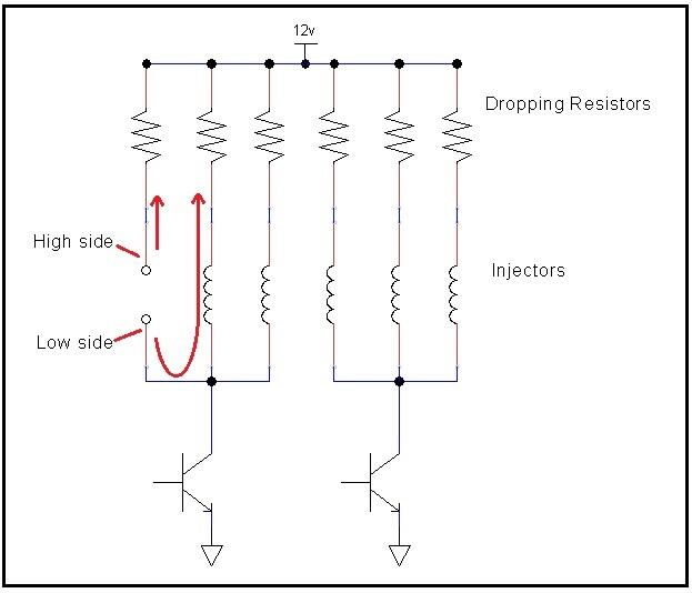
-
Yeah, I figured you were on top of that, but couldn't hurt to bring it up. And I hope you get your O-ring stuff worked out. Workmanship stuff is a real pet peeve of mine.
-
Cool. I think that would be interesting to compare against stock. Make sure you short your meter lead tips together and subtract that number from the injector resistance measurement. That shorted reading is lead resistance. For example... When I was measuring the injectors here today, I stuck both meter leads down into the injector connector and made connection to the blades in the JPT connector. I got 3.0 Ohms. Then trying not to move much, I shorted the tips of the leads together while also still connected to the JPT blades. I got 0.6 Ohms. In theory that 0.6 Ohms is lead resistance (plus crappy meter accuracy). Subtract the 0.6 from the 3.0 and I got 2.4 Ohms. The smaller the resistance you're trying to read, the more important it is to account for your lead resistance. Hoping this makes sense?
-
Page EF-56 of the 76 Manual says the dropping resistors should be 6 Ohms. I have not measured anything to verify. And I didn't find a spec for the injectors, but I measured a couple here and came up with about 2.4 Ohms. No accounting for the absolute accuracy (or inacuracy) of my meter, but that's what I got. Do you know the resistance of the high impedance injectors you are using?
-
I'm thinking that the higher the injector impedence is, the less impact the dropping resistors will have. What's the static resistance of the new injectors? In other words, if you put an Ohmeter across the new injectors and then do the same with the old, what are the resistances at DC? That dropping resistors would still be in series in the circuit with the "high impedence" injectors, but depending on the resistances, they may be overshadowed by the resistance of the injectors themselves. Voltage divider and all that. For example... If the dropping resistors are 1 Ohm and the injectors are 100 Ohm, it won't really matter whether they are included or not. That may be why you guys aren't seeing much of an impact whether the dropping resistors are installed or bypassed.
-
So I'm not sure how that pressure regulator is designed inside, but it looks like you've moved to a dead-headed setup at the rail? The original system is bypass scheme.
-
Perfect. Then throw the front cover on and fire that thing up!! Haha! I also noticed that you are running the eccentric cam to drive a fuel pump, but you certainly are not going to be running a mechanical fuel pump with that EFI system. Doesn't hurt anything, just unnecessary.
-
Looks way better! So I can see the timing mark on the cam sprocket. Using position 1 (which makes sense with new timing components), but I can't see the mark on the crank gear. Are you positive sure you got the timing marks correct?
-
Well I guess at the end of the day, your wideband would be the best determination of whether those injectors are appropriate. I'm interested because there's a local to me Z guy who is dealing with some injector issues. I've been thinking about just jettisoning the whole stock system like you have and moving to something different. I remember reading somewhere (hoovered) that the flow rate can be considered relatively linear with respect to fuel pressure. At least within a range close to the rated flow. So if something flows "X" at "Y", it should flow 0.83X at 0.83Y. Do you know what GM vehicles used those injectors you have there?
-
Yeah, that thing about the clamps being asymmetric is really weird. But after seeing so many sets with the same shape, it's clear that it was done on purpose. And I'm still not sure it really matters much. But since I'm a stickler for details like that!
-
" I thought it would be something more... obvious, like Right." Haha!!
-
How does the flowrate of those new injectors compare to the originals? I did a very little looking around a while ago and it seems the originals are low flow compared to most of the newer stuff.
-
I'm doing very similar configuration to what you did. I shaved .010 less than you did, but same P79 head and F54 block and also stock valves. I've got a second set of parts here, slack guide and tensioner. Maybe I'll throw them on just to see if they are any different than what I've got mocked up on the block now. In theory, if a manufacturer put a little extra plastic material on the end of the tensioner shoe or the slack side guide, it would change the positioning of everything. So I've got a different brand of both available.I I'll toss them on just to see how it looks. I think I have an OSK set here as well as an ITM. And sorry to the OP for the thread diversion. I know it's related, but still. Sorry for the sidetrack.
-
Duh. It stands for "Rear"?
-
If you look closely, you can see that the steering rack retainer straps are not quite symmetric. I'm not sure we ever reached positive consensus about the correct orientation, but here's a couple threads that talk about it: https://www.classiczcars.com/forums/topic/48621-steering-rack-disassembly-and-refurb/?page=15 https://www.classiczcars.com/forums/topic/65616-putting-in-a-replacement-l-28/?page=11 I don't think there is a left vs. right, but I do think there is a front vs. back.
-
Thanks for the details on the eccentrics. I was zooming in on your pic to see if I could figure out which eccentric you ended up with, but couldn't tell. Now I know why! Haha! If I would make my eccentrics, I would make them (just under) the full width of the gear web so I didn't have that issue. So, looking back at your .050 off pic again.... Are you sure you didn't use cam tower spacers or something? It just looks so different than what I found!
-
Neat idea. So why are you going to do both threaded retainer ring and little screws in from the back? Why don't you just concentrate on the threaded ring? You worried you can't get it to work out right? I'd be more worried about the screws in from the back. Such a short threaded length. Fiddly little screws that you're going to drop and lose on the floor. No room for locking hardware and vibrating out, etc.
-
@Jeff G 78, I also see you are using an eccentric bushing on a modified cam gear. Did you find that you needed to adjust the cam timing after you had the head milled? That's my next step and I'm in process of figuring that out now. I've got a cam gear modified to accept one of those GM style eccentric bushings, but I won't really know for sure until I have a real head gasket installed and the head torqued down. In theory, the milling of the head would retard the cam, so I'm thinking I might be able to just use one of the built in adjuster holes (either 2 or 3) to advance it back to where it should be. I also don't like the sloppy fit of the eccentric bushing on the cam locator pin. Bushing designed for a 1/4" pin, being used on a 6 mm pin. If I find I do need to use an adjuster eccentric, I'll probably make my own.
-
Yeah, that looks a whole lot better than mine did when I mocked it together. I put mine together with a used FelPro head gasket so there was a little bit of crush there, but I also had my head cut .010 less than you did. In any event, if mine looked like that after just opening up the adjustment slot, I would have been good with that. Maybe there are just differences between manufacturers of chain guides.
-
I'm thinking the same thing. Stackup of a whole bunch of things. So I test fitted my .040 shaved head and I still had too much stickout even with a whole new timing set. Even with filing the slot longer on the slack side guide wasn't enough to bring the tensioner back to home. I'm surprised you were able to do a simple slot lengthening with your .050 off and ended up with the tensioner all the way in. With my guide, there wasn't sufficient extra meat on the edge the guide to file the slot as long as it need to be. Maybe your guide was a different brand than what I used? I eventually had to take some more extreme measures with the guide. I'll post pics when I get a chance.
-
I took a look back through some of my notes and here's a couple points of interest: Stock head thickness is 108mm (4.252 inches). Couple USED head gasket I measured - thickness approx 0.045 (1.15 mm) NEW head gasket I measured - thickness approx 0.055 (1.40 mm)
-
The new timing set will certainly help, but depending on how much the machinist took off your head, even with all new timing parts, you might still find the tensioner sticks out further than it should. I've got typical head gasket thickness measurements around here someplace (not handy right now), but I'm thinking your 1mm head gasket is about .020 thinner than stock? So if the machinist took even .010 off the head, you're at a total of .030 from stock. Even with a new timing set, I'm worried your tensioner will still be out more than it should be. Maybe enough to limp you home, but still something you would need to address. All of this is very fresh in my mind because I'm sitting here looking at my custom chain guide that I'm working on in order to bring my tensioner stickout back to acceptable range with my just completed .040 shaved head. The .015 shims will help a whole lot, but then you run the risk of having your contact patch on the lash pads or rockers in the wrong spots. That said... I'm no engine builder, but I would be more comfortable with running with an incorrect contact patch for 60 miles than I would for that tensioner sticking out that far for 60 miles. And as for the head gasket... Again, I'm no engine builder, but if you haven't run the engine at all, I'd be comfortable with leaving the head gasket in place if you were to pop cam tower shims in there. Follow the correct loosen and re-tighten sequence and procedure on the head bolts and I'd expect things to be OK. Which route to take kinda depends on how quickly you need to get that thing out of your buddy's way.
-
And I'm not comfortable with this. I don't think you should start the engine like that, let alone try to make it 60 miles. It's just too risky.
-
So you had the head cut and are using a custom head gasket that is thinner than stock. Both of those will contribute to the issue you are dealing with. What about the timing chain guides (not the valve guides)? Did you replace those with new or are they the same ones that were in the engine when you started? This is one of the guides I'm talking about:
-
Coincidentally, I've been messing around with the timing chain and tensioner stuff recently and with that in mind, I'm really wondering why your chain has so much slack in it. I've compared a brand new timing set with all new gears, chain, and guides to a used set that has run 150K miles. Of course there was a some difference, but even the 150K used set has way less slack than what you have in yours. Now, of course, yours could be worn and stretched more than the used set I have here, but I'm thinking there could be something else going on. As part of your rebuild process on the engine, did you have the head cut? Having material removed from the head can have a large impact on chain tension. Also, you said you did not replace the chain or the tensioner. So what did you replace? Did you replace the guides with new, or are the guides used as well? I'm thinking if you got the head cut and reused all the old parts, that's what is causing the issue.


