Namerow
Community Member
-
Joined
-
Last visited
Everything posted by Namerow
-
Steve or Dave Zs-on-da-Brain can advise. I'm a mechanical engineer and only understand hammers ... although I'm pretty sure that solder is not going to get the job done (not for long, anyway)
-
Possibility #1is that you somehow hurt or confused the wiper relay during your original tests. The humming noise could be one of the contacts inside the relay vibrating as it tries to close. Put your ear close to the relay can and see whether that's where the hum is coming from. If it is, then a deft whack with a hammer might coax the relay back into operation. Or not. If the hammer fix doesn't work, you could try opening up the relay can and poking around to see if you can coax the thing back into life. Probably better, though, to just replace it. If it failed after 2 tries during bench testing, it'll probably fail again after you put everything back in the car. Probably when it's raining . Possibility #2: The worm gear in your wiper motor's gearbox may have jammed. I don't know how this would have happened, but the fact that you got two successful cycles on your original test before you ran into trouble suggests that possibility that the gear jammed at the end of the second forward cycle (maybe when the motor tried to go into auto-reverse? or maybe something broke off inside the gearbox housing and got lodged in the gears?). It'll be hard to fix this by trying to move the motor and the output shaft by hand, because it's essentially impossible to rotate a reduction-type worm gear system from the output end. You might be able to free things up by loosening off the load-adjustment screw that's located on the outside of the gearbox housing at the bottom of the worm gear shaft. If that doesn't work, you'll probably have to take the cover off the gearbox to see what's going on. Possibility #3: This is a WAG. Maybe, by some impossible coincidence, you stopped the motor at the end of the #2 test at the point when the reed switch for the 'PARK' position was j-u-s-t beginning to open, and now it's electrically hung up between 'off' and 'on'. To check, you can try moving the 'Park' switch to a new location. Look on the underside of the gearbox casing and you'll see a pie-tin shaped cover that's held in place by three screws. The cover has two wires coming out of it (from the reed switch). The edge of the cover has five or six notches and there's an indexing mark stamped into the gearbox housing to serve as a reference. If you loosen the three screws, you can rotate the can to change the location of the reed switch. Try rotating the cover by one index mark. Re-tighten the screws and hook up your power source again for another test. If this works, make sure you return the PARK switch to its original setting before you button everything up. Let us know what you do next.
-
Thanks, CO. I'll take a look in my local auto parts stores the next time I visit. In the meantime, I made my own spring and installed the full wiper assembly back in the car yesterday afternoon. Given the way that the spring clutch operates, I decided that it wasn't important whether the spring is made from tempered wire or not. In fact, it seemed to me that it might work better without the tempering -- so I made my new one out of 0.065" hardware store wire. I'm a little concerned about the durability of the tang, but only time will tell and, hey, if it breaks off, I'll just be back to 'normal'. My new spring came out pretty darn close in ID to the original spring, so that was good. The stack height was close, too (the OE spring is 2 coils in height). I also took care to wind the coil it in the same direction as the OE spring. I debated about whether the shoulder of the eccentric washer should be greased or not, but decided in the end that no grease could lead to breakage whereas grease - if incorrect - would only lead to clutch slippage (i.e. 'normal'). So, with everything back in the car, I hooked up a 12V power source the the appropriate connections and turned it loose. All good in 'HI' and 'LO'. Then the big test, which was to engage 'OFF' (you do this by opening the motor relay's ground circuit). The result? Well, I'm not really sure. What I know is that the motor and linkage stopped, paused briefly, and then reverse-rotated to the 'PARK' location -- where everything just stopped What I can't tell is whether the spring-clutch ever kicked in. I tried several cycles, thinking that the new spring might need time to bed in. No detectable change, though. I was running the system without the wiper blades attached (just a clothes peg mounted on each of the wiper shafts to give me a visual), so I guess that's the next step. My new theory is that it may be necessary for the motor and linkage to have a load to work against before the spring clutch and eccentric cam will do their thing during the motor-reverse sequence. If I'm feeling energetic after I get home from work tonight, I'll go back out to the garage and give it another try, this time with the blades installed. More tomorrow.
-
OFF doesn't just turn off the power. It actually sends a signal to the wiper motor relay that then tells the motor to operate in reverse until the output gear in the wiper gearbox reaches the PARK position. I think you've either pooched the relay or you've got a mechanical obstruction in the system that's preventing the motor from operating in reverse. Do you have the wiper blades installed?
-
I wonder if the wire is acting like an electromagnetic cage, so that it sets up some kind of adverse electrical field in the zone where you get the dull spot? You'll probably say, 'Why don't I get the same effect when I plate a regular flat washer?' My guess is that this particular part is 'deep' enough in section that it shows some of the plating characteristics of a hollow tube. If you're still feeling 'experimental', try this: Sandblast one of the two parts to take it back to bare metal (hopefully, this will get rid of any residual problems in the dull-plating zone). Now try a centralized supporting system for the part when it's in the plating bath. I'm thinking you could take a length of wire and wind it into a coil that's about 10% bigger than the ID of the centre hole in the strut cap. The idea would be for the wire coil to be under enough compression when you put it in the hole so that it will grab the part. This is just a WAG... but that's what drives scientific investigation sometimes. (When you enter the world of DIY plating, I figure you deserve to call yourself a scientist. It sounds a lot more confident that 'wizard' )
-
Nissan kept the FSM's relatively low-detail for the first three years. It wasn't until the 260Z arrived that the broadr descriptions and new, detailed diagrams started to appear. If you have a 70-72 Z, theres's a lot of worthwhile info to be had, provided you know how to filter out the stuff that doesn't apply to your model year. In the case of the Wiper system, for example, you have to ignore the discussion of the 'Intemittent' feature. BTW, I find it interesting that the plastic molding for the Combination Switch stalk in my 70 Z clearly incorporates a 'dot' (not painted) for a third Wiper speed setting. Kind of like they knew from the outset that they were going to add either a 'Medium' or 'Intermittent' setting later on.
-
Yep. Bench-tested two motors today and both demonstrated the reverse rotation when OFF was selected. Not always a full rotation, though. Depends on where Off is triggered during the the regular 360-degree rotation cycle. It`ll be interesting to see whether the rotational clutch has time to engage during the less-than-360-degree reverse rotation. I'll know soon, because I made my own replacement spring. Wiper assembly goes back in the car tomorrow, so I hope to be able to report tomorrow evening. Stay tuned.
-
Thanks, CO. I hadn't thought of the spring coil/uncoil in terms of it cinching down on the hub of the eccentric cam. Brilliant! A few minutes before I read your post, I found this in the 1974 FSM: That made me remember the eccentric cam, and then I suddenly realized that its purpose is to change the effective length of the linkage arm by about 1/4" when it rotates from one stop to the other (by way of the torque applied by the spring. Another S30 mystery solved! BTW, I've had good luck making my own helical and hairpin springs from music wire. The OE spring in the wiper linkage is made from 0.065"-diameter wire. I have some (OK, a lot of) 0.040" music wire. Not perfect, but maybe close enough. I just need to make sure that my coil that has the right 'grabbing' diameter. If it works, I can start selling them for $50 a pop and retire. Let's see: 100 buyers @ $50 each = $5,000. No good. Guess I'll have to keep my day job after all.
-
So, CO, I have a question, then: You haven't really explained how the 'rotational clutch' action actually works. We know (because you told us) that the motor is supposed to spin backwards when the wipers are turned off. We also know that: the 'park' position for the wiper arms can't be any lower than what the crank arms will allow, meaning that they won't park any lower than their lowest point of travel during regular operation. That seems to be at odds with what you're saying, but maybe -- with a bit of encouragement from some reverse wind-up in the rotational clutch -- the arms might appear to tuck a bit after the motor shaft stops at its 'park' position. the spring seems to only be engaged at one end (i.e. the end where the tang locks the 'shield' plate (millenium falcon piece) to the end of the linkage arm. I can't find any evidence that the other end of the spring engages with anything. It seems to just push against the underside of the washer that sits on top of it (and even if it did, that washer has no tangs or indents, so it's rotationally free and can't transfer any torque from the spring to the linkage arm) the keyed center hub is free to turn on the centre shaft but it doesn't engage with the spring. In fact, it only engages with the keyed washer that sits on top of the parts stack and that washer looks like it has the ability to rotate +/- 180 degrees, with end travel limited by the raised edges of the linkage arm. So it seems that the assembly can only exert clutching action if the free end of the spring engages with something under certain circumstances. One possibility comes to mind: when the motor spins backwards, the free end of the spring bites into the underside of the washer enough to make the spring coil expand to the point where the free end of the spring bites into the raised lip of the shield plate, at which point the spring starts to exert some actual torque into the linkage. This sort of makes sense to me. I have two of the units disassembled on my workbench at the moment and on one of them the shield plate has four or five ragged holes poked into the lip at random locations around the periphery. The holes are just about the same diameter as the spring (in fact, if you look at the picture that SurferD posted at the top of this thread, you'll see exactly the same kind of hole in his shield plate. And then there's a cryptic note that somebody made somewhere (I don't remember where) that said that on later units there is a 'plastic ring' that been added that sits around the outside of the spring (can anyone verify?) So, Captain Obvious: How does this thing really work? What happens to the spring when the motor turns backwards? p.s. On both of my springs, the tang has snapped off. When I tried to bend a new tang onto one of them, it just snapped off so no joy that way. I'm going to see today if I can maybe put a sleeve made of brass tubing over the end of the spring and then bend the tubing to form a substitute tang. Might work. We'll see. I have other ideas if it doesn't.
-
I think Gav240Z's recommendations are on the money. The minute you start personalizing/customizing/improving a car, it looses its appeal for collectors and you limit the potential-buyers pool to very small group of individuals -- people with exactly the same taste as you, but who lack the skill, time/patience, or facilities to do the work themselves. They have to trust your workmanship, too, or else they'll be looking for a bargain on the price to help compensate for the uncertainties. Buyers with deep pockets are looking for originality -- preferably non-restored originality, right down to original paint and interior. For proof, look no further than the 260Z that just brought $46K on BAT. While most of us on this site consider the 260Z to be the red-headed stepchild of the Z family, the collector who paid big bucks for the car clearly had different motivations. More BAT examples: A very clean and original 240Z located in Montreal recently attracted $33K, IIRC. It probably would have brought even more had it: 1) not been located outside the USA; 2) not been Ziebart rust-proofed (although it seems to be one of the few examples of a Ziebart job that actually worked), and; 3) not had the engine compartment re-sprayed. A couple of years ago, a bone-stock 72 240Z (located in Toronto) with an undesirable red-over-white color combo (but original paint) and an auto trans also brought over $30K. This one, too, was probably hurt by being offered by a seller located outside the USA
-
I did this replacement earlier in the year. Very pleased with the end result as there is now zero slop (more like, 'click') in the front and rear joints. A couple of tips: When you reassemble, it helps to chill the needle cups before inserting them into the yoke. I used a spray can of 'Part Freeze'. Doesn't hurt to also warm up the yoke ears , too. I used a heat gun. When you're pressing the cups home in their bores, be careful not to let one of the cups go too far so that it travels past the inside face of the yoke. When this happens, the cup behaves like it has a slight draft angle and it won't back up into the bore. Maybe it gets cocked a bit sideways, too. Whatever. Bottom line is that the cups will go one way (in), but they won't go the other way (out). I learned this the hard way and ended up having to cut a brand-new spider in half in order to extract the cup from the yoke. After that, it was back to the cycle shop to buy another one. You may need to dress a bit of metal 'flash' off certain edges of the spider casting (forging?) before you'll be able to get the second yoke in place. You'll know which edges need to be shaved when you try to assemble the parts. You won't need to remove much more than ~ 1/64", but without doing this there may not be enough clearance to get the second yoke ear to fit over the ends of the spider. What with chilling, heating, and pressing, you're probably going to make a bit of a mess when you're doing the re-assembly, so save any painting until everything's back together.
-
This is a well-travelled topic that's been discussed for the past 40 years. Perfectly-tailored fit is a nice-to-have, but not a need-to-have. What you need is a combination of outer and inner materials that won't hurt your paint. Trapped moisture can kill an expensive paint job. My suggestion: Go to a Ferrari owners website and have a look at what's considered to be the accepted standard. What you're looking for is experience-based advice coming from people who won't tolerate bad surprises.
-
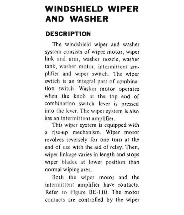
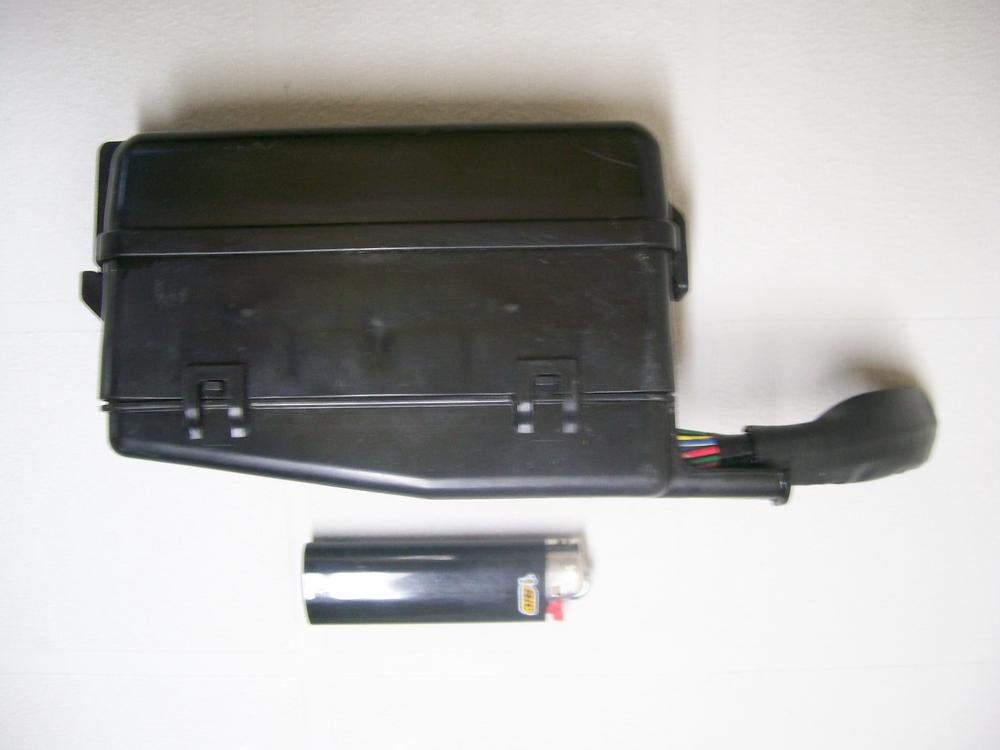
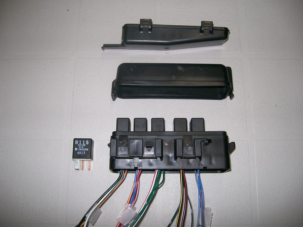
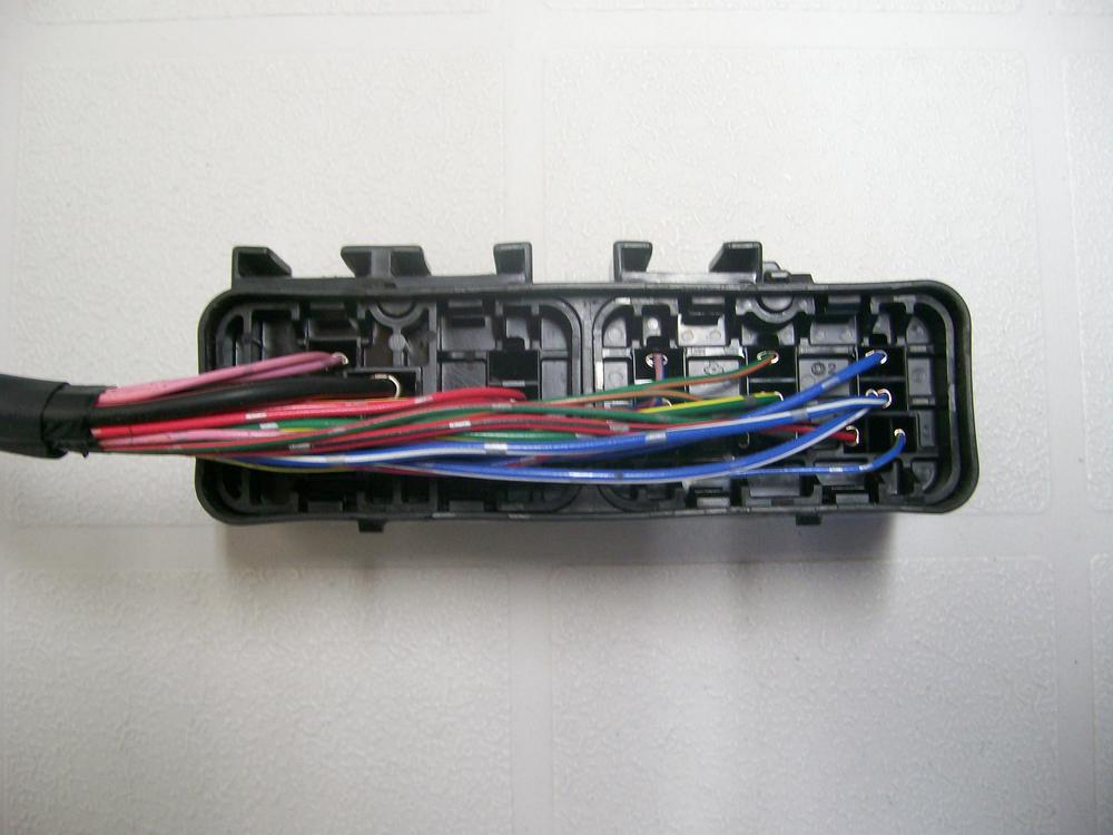
I'm using a very compact little relay box that I pulled out of a 2000-ish Mitsubishi SUV at one of the local boneyards. I had to do a bit of internal re-wiring, but ended up with a configuration that holds 6 relays. I plan to mount it up towards the rad bulkhead, in front of the voltage regulator. It's waterproof and dustproof, with a snap-off inspection cover.

-
Another example of how 'creative destruction' can reveal the inner workings of an assembly that usually just gets taken for granted. Does the inner cup make metal-to-metal contact with either the top cap or the spring perch, or does it 'float' 100% within the rubber? If it floats 100% (and I'm guessing that it does), the thickness of the rubber that separates the top of the inner cup from the underside of the top cap is going to be important. Do you have any sense, or way of measuring, what that thickness was/is for the original configuration?
-
Chris: Why not contact Steve at 240Z Rubber Parts? He's been casting soft and hard 'rubber' parts for a couple of years now and should be able to offer some useful tips on materials and processes. Use the 'Contact Us' link in his website.
-
Contact zKars. I'll bet he's got a drawer-full of these in his storage room. If you're in a hurry, though, there's no reason why you can bend your own. However, you'll need to temper the steel afterwards, or else they'll just bend and pull out after you've sat on the seat a few times. Heat the formed clip cherry red with a propane torch, then dunk it in cold water. Not terribly scientific, but close enough.
-
Nice write-up, zKars. A few additional questions for you: For an SU application, what is it that creates the end-of-travel (WOT) stop for the system? Does the 'commercially-available arm' hit a stop? Does the pedal hit its stop? Or do the throttle plates hit their stops? How does this affect the travel distance of the pedal, from rest position (idle) to the point where the system hits its stop? Where did you source the M8 ball-sockets and the 'commercially-available arm'?
-
-
Non-chemists messing with chemistry = alchemy As an engineer, I hate 'hit-and-miss' when I know that science offers a better solution. Unfortunately, I'm not a chemical engineer
-
Hah! That depends on your definition of 'finished'. I completed everything I wanted to do, with the exception of the my hood prop rod. I bought a replacement prop rod from Zkars and it arrived after I'd put the chemicals away and after I'd given Grannyknot back his controllable power supply (which I suspect he figured he'd never see again -- Chris a remarkably generous, patient, and polite guy). Some observations from my electroplating experience: To anyone just getting started on a plating project, I recommend you ignore all the 'budget' plating articles you'll find on the internet. I spent so much time and money experimenting with these DIY, low-buck recommendations (epsom salts, corn syrup, vinegar, etc.) that I would have been better off spending $500 to get a commercial outfit to do the work for me. If you really want to do it yourself, just hold your nose and buy the (premium-priced) Caswell chemicals. They work pretty well, for the most part. Even with the Caswell chemicals, there's a lot of trial and error involved. To get a good end result, everything needs to be right and there's zero tolerance for parts that haven't been properly cleaned and prepped. I hindsight, I don't think electroplating scales down well to the 'hobbyist' level. Or to put it another way, I suspect that, 'The bigger the vat and the heftier the power supply, the better the result'. I had mixed results trying to do multiple small pieces at the same time. This just seems to increase the chances for error. The 'Mount Everest' for my S30 plating project was getting a good result for the two-piece engine inspection light housing. With it hollow configuration and welded-on mounting bracket, it's hard to get complete, even plating coverage over the outer surfaces. It took me two tries to get a result that I was (sort of) happy with. Plating longer pieces (like the hood prop rod or the rear engine coolant transfer tube) will force you to buy a double-quantity of the Ca$well chemicals in order to get a bath volume big enough to plate these pieces in one shot. I don't think I'd try this job again without a controllable-voltage/current power supply (add $100 - $150 to your budget). I tried using a fixed-voltage power supply to start (I used a daisy-chain of automotive 12V bulbs to control the current), but it was a PIA and the results weren't very good either. I remain a little concerned about the durability of the yellow chromate finish on my parts. On some pieces, it would wipe right off. Some people suggest that the parts have to be baked in an oven after plating. Maybe this 'locks down' the chromate? I'm thinking about trying a two-stage powder coat as an alternative to yellow zinc plating. There are some pretty interesting 'glaze' top coats available these days.
-
I used flexible sanding pads (foam-backed sandpaper, about 400-grit) to remove the heavy tarnish, followed by fine-grade 3M sanding cloth to bring up the shine. After that, I dipped a piece of cloth (lint-free) in satin-finish clear enamel paint and used this to hand-apply 2 cover coats along the length of the line. This work was done over a year ago and the lines still look great, with no signs of corrosion. The OE steel lines shine up very nicely and don't really need a color coat. Depends on your aesthetic preferences. Applying the clear coat with a wetted cloth makes this part of the job really simple and mess-free. If I showed you one of the finished pieces, you wouldn't be able to tell that it wasn't sprayed on. Use a dust mask when you do the sanding. The sanding residue that comes off the lines is pretty evil and seems to fill the air while you're doing the work.
-
FWIW, I found that I had to keep 'doping' my bath with the Caswell's 'brightener' liquid to keep my zinc plating coming out shiny. It worked really well.
-
Another option (which may or may not appeal): Rubber/neoprene grommets respond really well to 'super glue' (aka KrazyGlue'). Just slice the grommet across half its width, position over the cables, apply a drop of glue to the cut surface, carefully line up the edges, and press together for 30 seconds. Job done. If you do it carefully, the joint will be pretty much invisible... and more than strong enough to withstand the distortion of the grommet when you push it into place in the hole in the firewall. If you need convincing, buy a generic grommet from the hardware store and try it out.
-
Just did this job myself. To confirm for you, the lip faces away from the hatch opening (i.e. faces to the front of the car for the section that goes over the top of the hatch). Before you get started with the adhesive, use a paint-friendly cleaning liquid to clean both the pinch strip surface and the surface where the lip will seat. Use the same cleaner to clean the inside groove of the weatherstrip, as well as the bottom surface of the lip. Apply a light coating of weatherstrip adhesive to the inboard edge of the pinch strip. Also apply a thin smear of adhesive to the underside of the weatherstrip lip. Forget about applying adhesive "to both surfaces" (overkill). When installing the weatherstrip, start from the centre of the top of the opening and work outward to one side and then down. Then go back and do the other side. The weatherstrip will stick pretty firmly right from the get go, so go slowly and avoid creating wrinkles. Be extra careful around the upper corners of the opening. The pinch strip isn't very tall and it's easy to miss the actual contour of the corner when you're pushing the weatherstrip into place. Pushing a length of clear-vinyl tubing (1/2" diameter?) down into the groove so that it presses down on the lip will help to seat the weatherstrip properly (especially around those two corners). If you don't remove the hatch from the car, it will be a bear of a job (maybe impossible?) to install the weatherstrip properly over the top of the hatch opening. Probably a good idea to apply painter's cling-film over the roof and rear quarter panels around the opening before you get started with the adhesive.
-
Well, not quite NLA... but close ($145!) http://www.ebay.com/itm/Datsun-240z-280z-Differential-Bar-Stopper-Mount-Bushings-Upper-Lower-NOS-/282099223385?hash=item41ae6c8b59:g:w4oAAOSwY45USAog&vxp=mtr