Namerow
Community Member
-
Joined
-
Last visited
Everything posted by Namerow
-
Solution is simple: Don't get in a front-end collision . I'm curious to learn more about how you braced the car in the vertical direction before you jacked up the low side.
-
If and when you do any pulling to take out the twist, here are some safety tips that I found online. They're not all appropriate to a unibody repair or to the type of repair you're going to attempt, but they'll give you something to think about... Inspect clamps and chains before each use. Wrap chain around a frame member several times. Do not twist the chain. Place padding around sharp corners of frame members that rub against the chain links. Ensure that the chain hook is connected to a link with a firm grip. Test it before applying tension or hydraulic pressure. Place a heavy blanket over the chain and clamp before pulling to minimize fly-back if the chain breaks. Stand to one side of the chain, not behind it. Stand behind a strong acrylic plastic or safety glass shield during all but the lightest pulls. Use two or more chains for pulls that require a great deal of force. Reinforce weak parts before pulling. Check the level of hydraulic fluid. Inspect hoses and connections frequently for leaks and general condition. Screw all body attachments (clamps or hooks) on tightly. Avoid damaging threads on the attachments. Replace damaged links with same quality and size of link. Do not use temporary threaded links for high stress applications. Teeth of clamps need to be clean and dry. Inspect clamps and chains for wear. Replace clamps that have worn teeth. Replace the chain if it is nicked or otherwise damaged. Make sure the chain is rated for the intended pulling force, including a large safety factor. Remove all undercoating where the clamp is attached. Before attaching the clamp to a rusted panel, tack weld a metal brace to the panel for support. Have the vehicle on its wheels or bolted to mobile safety stands when pulling. This prevents the vehicle from falling off the stand during the pull.
-
Charles: Would you mind also measuring between the centre of the front shock towers, if convenient? FSM says 913mm. Interesting that your measurement of the pinchweld separation distance (51.25" = 1302mm) is smaller, rather than larger, than the 1326mm value I got from scaling off a screen blow-up the FSM diagram. The difference is almost exactly 1.0"... which makes me suspicious.
-
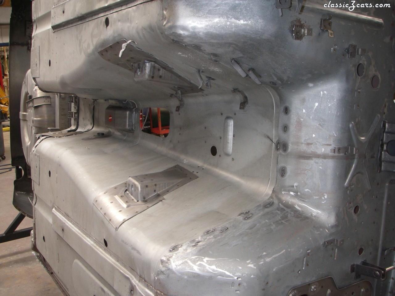
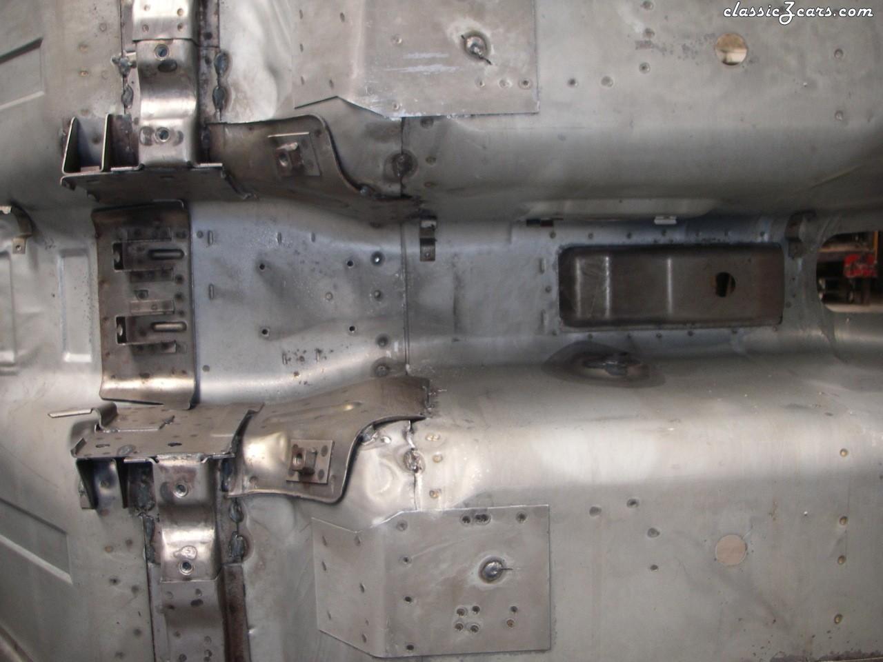
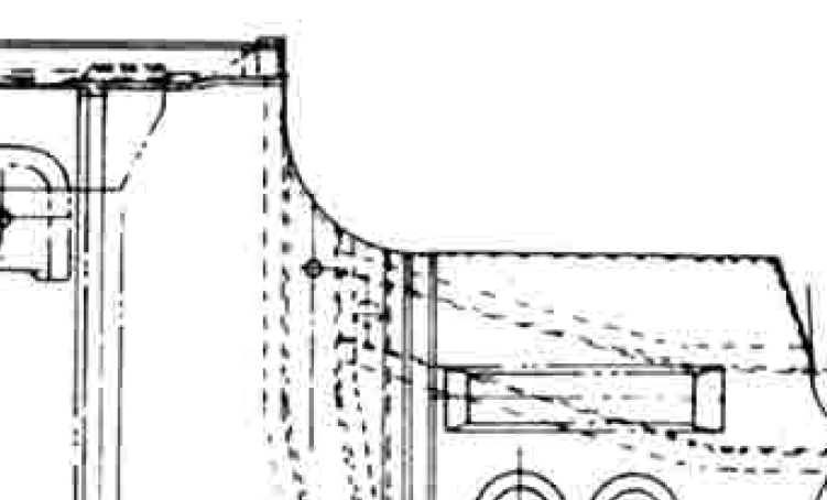
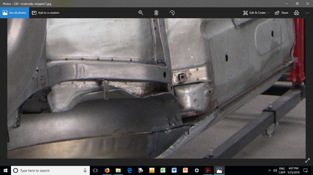
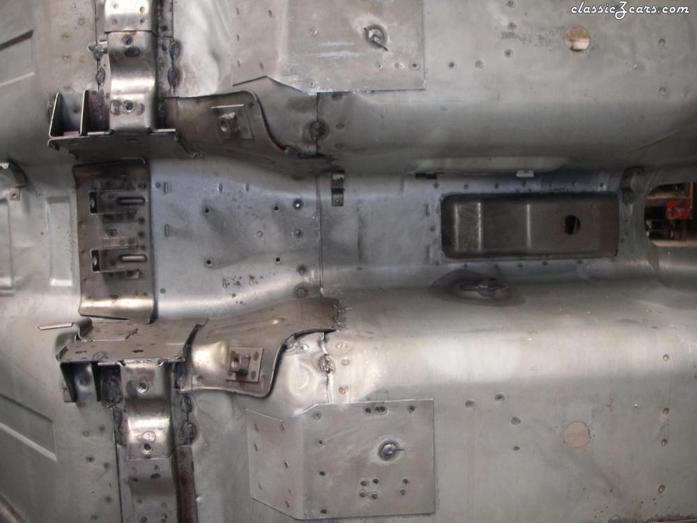
Nope. I think the 'C' point is something that you have to mark for yourself, based on the visual info inferred (implied?) by the FSM diagram. It seems to be in line with the outboard wall of the longitudinal rear sub-rail where that rail ties into the front transverse sub-rail, and then positioned dead-centre on the front transverse sub-rail. Note that there is a hole (factory-punched) in the transverse rail in that vicinity, but it sits about 1/2" outboard of the location that the FSM diagram suggests. Who knows? Maybe the punched hole is the C-point. It would certainly serve quite nicely for purposes of fore-aft measurements, but it would be off a bit for width-wise and diagonal measurements. See pix below (and, again, apologies to the unknown owner of the newest photo I'm about to post):
-
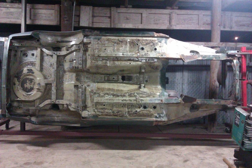
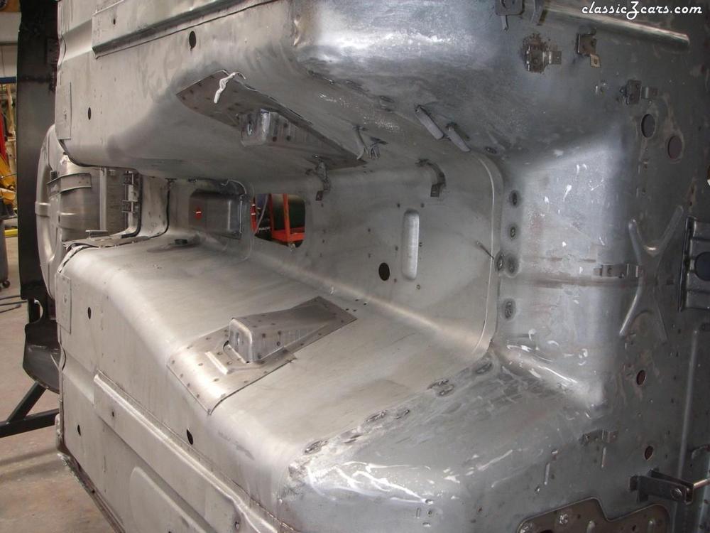
That's an interesting measurement. My initial thoughts are: It's hard to believe that the LHS and RHS pinch weld lines weren't designed to be anything other than parallel. Proving that with 100% accuracy is another matter, of course, because we have only the FSM 'Standard Body Dimensions' diagram as a reference and it doesn't even specify the left-to-right separation distance of the pinch weld lines. I've just tried doing a blow-up of the diagram on my screen, so that I could scale off the separation distance and compare it to a marked measurement. I get 1326mm. The accuracy of a derived measurement like this is probably +/- 2mm. Still doesn't solve your predicament. How do you find a centreline for a unibody? That's a great question. It would be nice if the design included an alignment hole at the front and the rear -- but it doesn't. At the back, you have the two 'C' holes drilled into in the rear sub-frame piece. Plumb those two, then measure and mark a centrepoint. At the front, however, you don't really have anything obvious to work from. Whatever you choose, you need to make sure it's not compromised by any of the collision damage -- everything ahead of the firewall probably needs to be treated as suspect. Finding the mid-point between the pinch weld strips under the front edge of the doors might be as good a reference as any. Collision repair sources say that "3mm" is the accuracy that they shoot for. I believe that, in practice, this means they work to +/- 3mm, rather than +/- 1.5mm). So that means they're happy with a left-to-right discrepancy of up to 6mm ( about 1/4") on wheelbase, or any other pair of long-ish measurements. The rotisserie photos below (unknown source, so apologies for no photo credit) may give you or somebody else has some better ideas about how to find and mark a centreline. The racers in the crowd are probably the best source of information on how to do this and on, 'how close is close enough?'. Track damage is pretty common occurrence and race cars usually get repaired rather than replaced.

-
Don't try to peel the glass off by pulling up on one end. Better to try to run a thin blade between glass and frame. The blade on a putty knife might be too short to offer enough reach. A metal kitchen spatula might be a better bet. There's supposed to be a rubber gasket between the glass and the frame. A bit less than the wall thickness of a bicycle inner tube, IIRC. On its own, this might stick enough to generate a lot of resistance to separating the glass from the metal frame. If the PO decided to 'improve' it, or even replace it, by using RTV sealant or the like, you may have a battle on your hands.
-
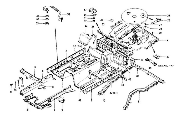
Further to Grannyknot's comment, I suppose you could be tricked by certain diagrams into thinking there's a separate frame... ... but there really isn't. It's just a collection of panels, ribs and rails, all spot-welded together.
-
Ace F1 driver Pete's bored, cheatin' wife describes for him a party she had the pleasure of dropping in on, on some unnamed Greek island... "... and there was ouzo. Lots of ouzo.'
-
You stole that line from the movie, 'Grand Prix', right?
-
Interesting find. It never occurred to me that there would be supplier(s) out there whose sole target market is the rebuild industry. I was thinking more along the lines of a local shop doing a customer a favor, rather than a full-on parts rebuilder. Maybe Steve/nix240 will get interested and cast up his own version of replacement .
-
I agree that your unit looks quite restorable. CZCC member 240260280Z (previously known as Blue) has a posting somewhere that shows a detailed teardown and repair of one of these units. He used RTV sealant to repair the damaged internal vacuum liner. That liner is, I suspect, unobtainium as a separate service part (contact Courtesy Nissan to confirm), so a local brake rebuild shop is probably going to have to patch yours, rather than replace it. There is now another way to go about this, though. Motorsport Auto have begun to offer an 8" mastervac unit for use in 70-71-72 Z's... http://www.thezstore.com/page/TZS/PROD/classic01a/24-5760 They say: "This unit is designed to bolt directly in place of the 70-72 master vac while working with the original master cylinder (not included). In fact, no modifications are required to run this booster beyond removing the old unit." Not inexpensive at $325, but probably good value for the money, all things considered. Only an expert would notice the difference in canister size.
-
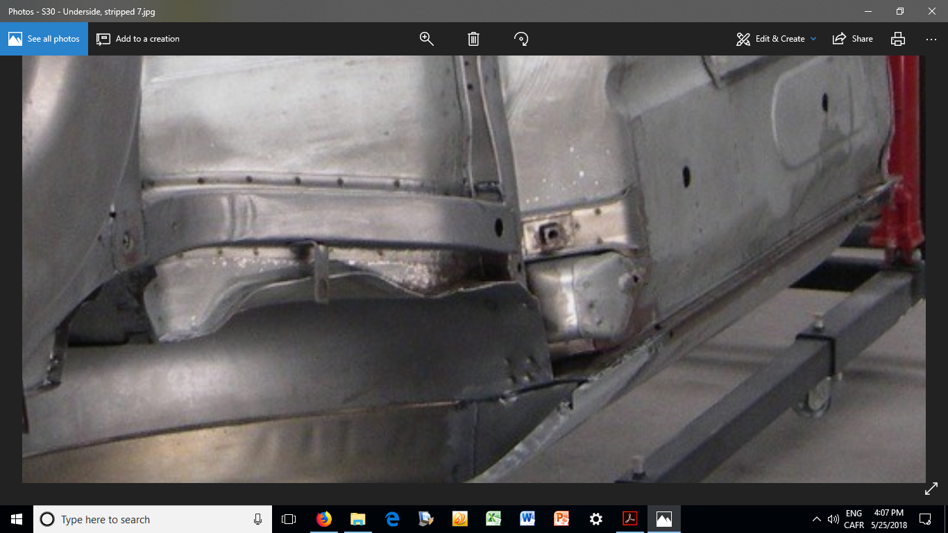
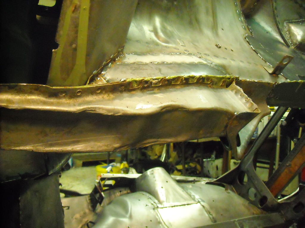
Would that denting in the main frame member have looked like this? (taken from Grannyknot's Z-M3 build thread)... Does anyone know how this happens? Hard to believe that this is collision damage. It looks, instead, like damage cause by a hoist... but one would have thought that the rail would be strong enough here to withstand the load. Also puzzling is how the damage appears to have been inflicted in two different locations. Does that mean that a second mechanic (or owner) chose to ignore the damage created on an earlier occasion and then went ahead to prove that the same mistake really can be made twice? I'm thinking that maybe this type of caved-in rail results from the use of a bottle jack. Comments?

-
I don't visit Hybrid-Z very often, but that's a good post. The author makes a point of emphasizing the challenges and things to watch out for, rather than just posting a fluff piece about how easy it was. I hope we'll see more write-ups on wraps because I think they may be the path forward for automotive finishes. In fact, it's going to be really interesting to see whether vehicle manufacturers will transition from paint to vinyl wrap in the near future. Production-scale paint facilities are extremely expensive for them to build, operate and maintain. And then there are the environmental issues (even with water-borne paints), the electrical power consumption costs, the cost of the paint, and the QC/QA challenges. I don't think that 3M got into the automotive wrap business line because of the customizer aftermarket. I think they may have their eyes on the larger prize. As for those of us who occupy the DIY sector of the old car hobby, I have to wonder how long paint can be justified over a professionally-done wrap. It seems that a garden-variety paint job by a body-and-paint shop starts at about $5,000 these days (unless you have a relative who runs a shop), while a pro wrap looks like about $1500. That price difference may start to resonate if/when word gets out within the hobby that a professional wrap can compete with paint for both appearance and durability.
-
When you start playing with the adjustment screw, I think you're going to find that the adjustment window for optimum sound/volume is pretty narrow. I suggest that you loosen the screw to 75% of its full travel to start. Then, with power applied to the horn, start tightening the screw. Take the horn past its point of max. volume, then back the screw out to re-find that point.
-
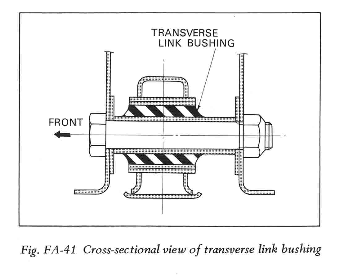
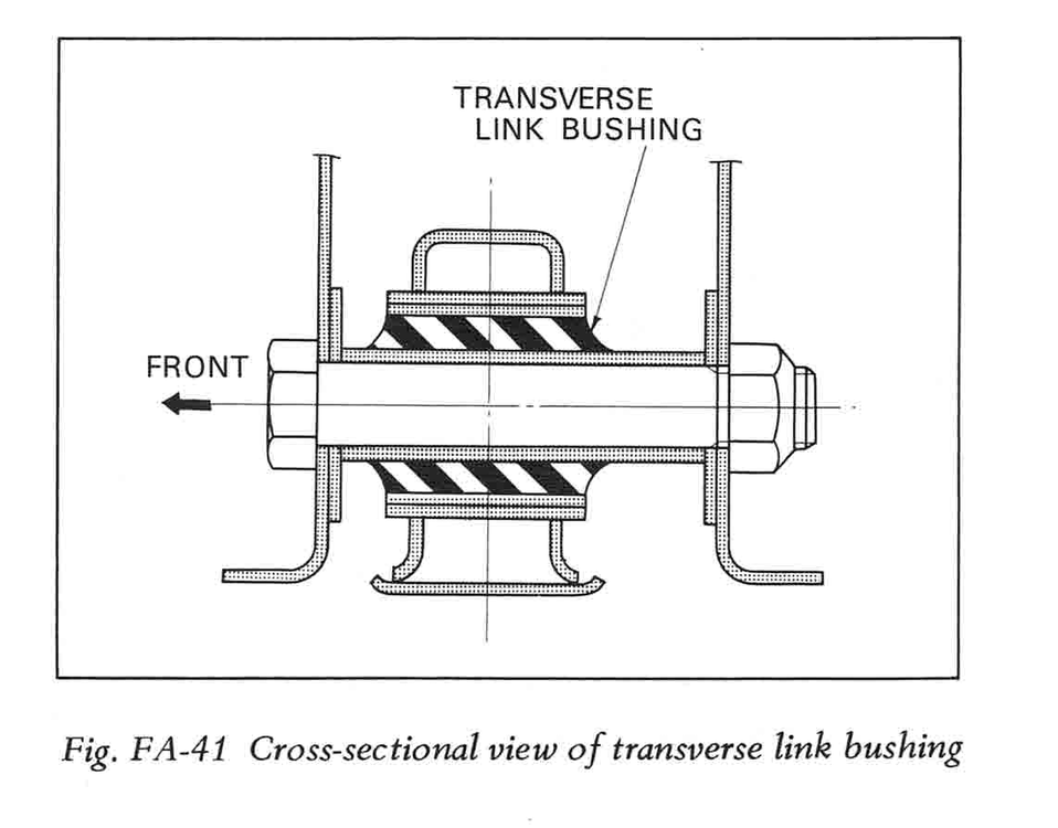
FSM (197 version, as shown below) shows the correct orientation of the lower arm bushing quite clearly... As for locating the compression rod mount bracket correctly, why not try to make up a filler disc that you can temporarily glue into the bracket's big hole. Perhaps a piece of hardwood dowel, sanded down so that its OD is a snug fit inside the hole in the bracket. While you have the dowel chucked into a lathe or drill press, you would drill a centred hole (say, 1/16"). Once done, cut a 1/4" length off the dowel. Now you have a disc with a centred hole that you can glue into the bracket hole so that its front face is flush with the front face of the bracket. The drill hole should provide you with a pretty decent reference point for making your alignment measurements.
-
I like this idea in principle. The assumption that the door sill surfaces are flat, front to rear, is probably a good one, but should maybe be tested with a straightedge, just to be sure. The assumption that the door sill surfaces were designed to be parallel to the OE front frame rails' top surfaces is probably also a good one, but hard to prove. You may need to take this as an article of faith. The straightedge strategy that Patcon is suggesting would require you to get the support points for the two straightedges (one front, one rear) up high enough so that the they will clear the transmission tunnel. Maybe a pair of 1"-thick rectangular panels (MDF?) cut to 9" x 30" on an accurate panel saw (like the big ones at Home Depot or Lowes), then crossbraced with a few of lengths of 1 x 2 to hold them vertical, parallel and at the right separation distance. Once set down on the door sills, you'd now have something substantial on which to lay the straightedges. Question: How do you now use these door sill straightedges as a datum to see whether the frame rails run parallel to the door sills? More straightedges? Laser? Strings? Plumb bobs?
-
Motorsport Auto PN's 34-1058 (left) and 34-1059 (right) $20.00 per side
-
Sometimes I wonder if there's ever been another car that's suffered as many indignities from 'customizers' as the poor Z has.
-
OK, so who wants to try this out first? Pictures too, please.
-
Anyone care to comment on the safety precautions needed before cutting or welding a gas tank ? Have the tank 'boiled out' by a rad shop? Fill with water? Wait for __ months to let the fuel vapors diminish? Just curious.
-
hmmm... You mention buying new felt washers (a good idea) in the same sentence where you talk about cleaning the bronze bushings (also a good idea). However, the bushings with the felt washers are not the ones that bind up. Instead, it's the bushings inside the cast-aluminum mounting blocks that locate immediately underneath the base of each wiper arm. These are the bushings that really count when it comes to freeing up the overall system.
-
A few cautions: The circlip that secures the centre linkage on the motor shaft might be a bit tired. Replace it if you're in doubt. The centre linkage is supposed to be covered by a dustboot. In most cases, the OE dustboot has disintegrated and will probably by MIA. Steve (nix240) offers a nice replacement piece. Your chances of finding an OE Nissan dustboot are slim to nil. As has been pointed out by many others, the primary culprit for slow Z wipers can be found in the bushings provided for the left and right-side wiper arm drive spindles. The original grease coagulates into something that has zero lubricating properties and, instead, creates a lot of binding between the bushing and spindle shaft. Clean everything out and repack with a modern, synthetic grease. Some say that this simple step makes the need for the Honda wiper motor upgrade unnecessary. It's possible to put the crank arm back on the motor output shaft so that it's 180 degrees off. You can't tell which way is right unless you mark the arm and the end of the motor shaft before you disassemble. If you get it wrong when you reassemble, the wiper blades will sweep down rather than up, ruining the paint on your cowl panel. To protect yourself from this calamity, don't install the wiper arms until you're sure you've reassembled things correctly. To check without risk, just put a clothes peg or even just a piece of masking tape on the end of one of the wiper blade spindles to simulate the wiper arm. Then watch which way things move when you turn the wipers on.
-
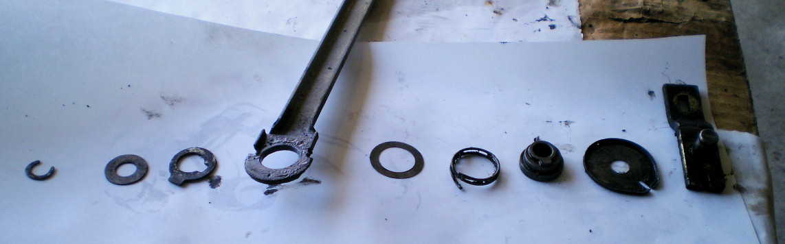
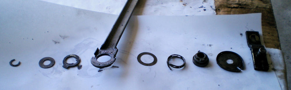
The photo below will show you the correct assembly order and up/down orientation for the linkage parts (sorry, but I don't have the name of the original poster so can't provide credit). To assemble, just start stacking the parts on the crank arm spindle, working from right to left. FWIW, I did a lot of experimenting with this assembly last year to see if I could discover the purpose of the spring and the eccentric bushing. My conclusion is that the eccentric bush is there provide some compliance in the linkage (so that the long connector arms don't bow or get over-pulled), while the spring is supposed function an anti-slop device (which it might if the tang wasn't broken off -- which it almost always is). I concluded that the spring has nothing to do with the 'auto-rise' function (which was just Nissan's way of saying the the wiper motor parks the blades a bit higher than their lowest wiping-mode sweep point).
-
Looks very promising. The question now is whether the softening effect is long-lasting vs. temporary. Hope you can give us a few updates over the coming weeks. Even if the effect turns out to be temporary, it may prove to be valuable during the installation of components where some 'give' is needed (such as the fuel filler neck that you've shown in your video). I find it curious that none of the commercially-available 'rubber and vinyl softener' products come anywhere close to delivering this kind of result.
-
This UK article might provide some additional insights into product differences and techniques for surface preparation... http://www.realclassic.co.uk/techfiles/tank_cleaning_and_sealing.html You might even consider corresponding with the author, as he will offer the benefit of multiple experiences rather than just sample-sizes-of-one.