



Zed Head
Community Member
-
Joined
-
Last visited
Everything posted by Zed Head
-
Doesn't @Captain Obvious have a 77?
-
If his did he should not have the ballast resistor. That is the quandary. He said he has the ballast. If he has something he shouldn't then maybe he doesn't have something that he should. Post the number of the module. I think that that will tell you.
-
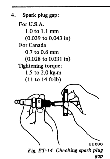
Looks like 77 already has the high energy ignition. I always get the change mixed up with the fuel pump control. 77 was kind of a mid-change year, it still has the old AFM pump relay switch, I think. Posting before I see ckurtz's reply... Weird! The FSM says you shouldn't. Probably a mid-year change. So, if you're using the FSM tuneup spark plug gap, you'd be using a wide gap on a weak ignition. What plug gap are you running? Migth be a small part of your problem. Either way, the GM module will give more energy and allow the larger gap.
-
I just looked at the 77 tune up chapter and can't tell if you have the old style or the new style. I thought 77 used the ballast resistor but they don't show it there. Do you have a ballast resistor by the coil?
-
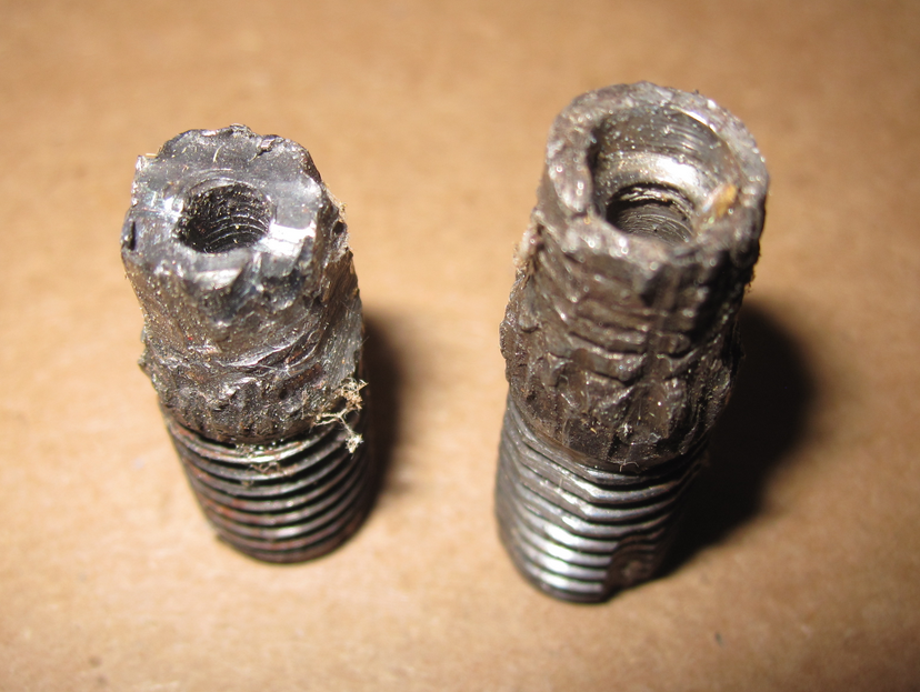
It might be that the 3rd piece is doing all of the work. Be careful. Do those two pieces have jagged edges like they broke off of something? I recognize the tooth pattern but can't tell where it would have come from.
-
Multiple spark discharge ignition was kind of developed for race cams so they could get cleaner low RPM performance. MSD built their company on it. It might help. And raising your idle RPM will probably increase your vacuum reading. These are the small things the guys that get theirs to run just fine don't tell you. You could swap to a GM HEI module really easily for cheap and you'll get a stronger spark. Get rid of the ballast resistor and keep the Flamethrower. When you say rebuilt distributor you don't mean a ZX distributor, right? You're still using the module down by the fuse box. Here's some MSD history. https://en.wikipedia.org/wiki/MSD_Ignition
-
Wow, that is not a synchro ring, looks more like part of a coupling hub. I've only pondered the insides of a trashed 5 speed after I took it apart, so don't really have the memories of somebody who has rebuilt one. Looks significant though. You might start browsing the ads for another 5 speed, just in case. Always good to have spares. Even a 4 speed will get you by.
-
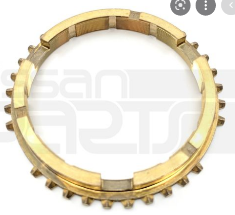
@EuroDat will have a better idea but it looks like the remains of a synchronizer/baulk ring, but kind of different. Can you take a picture of the teeth on the parts? They look wide. The other magnetic parts might be bearing parts, which might have caused the synchro ring failure. http://www.carpartsmanual.com/datsun/Z-1969-1978/power-train/transmission-gears/5-speed https://www.nissanpartsdeal.com/parts/nissan-ring-baulk~32604-p0100.html https://www.ebay.com/p/1529633534 https://www.nissanparts.cc/oem-parts/nissan-ring-baulk-s12-z31-720-c31-c32-d21-r31-32604p0100
-
Are you running the 1977 ignition system? 1977 was still using the weak electronic system. Your cam is going to cause variation in the gasoline/air ratio, especially if you try to maintain a low idle RPM, plus the batch fire nature of the old EFI system also causes variation across the cylinder. A better ignition system might help.
-
Didn't know you were running a lumpy cam. That thread from zcar.com is interesting. A lot of what would be considered bad advice on how to get the 260 cam to run "right". Fiddle with the AFM, run direct vacuum advance, adjust the TVS so it's off-idle. wangsman's version of "runs great" seems to be pulling hard to 6000 RPM. Your issue is at idle. You can tell from the comments that some of the opinion might be more of an "I made it work" view. I'll bet their cars smelled like raw gas at idle. No offense to the two guys that said it can run just fine with the lumpy cam, but that's how the brain works. We probably all have memories of the guy in high school that thought his car was fantastic but nobody wanted to ride with him. @Jeff G 78 is one of the guys in the thread. He knows a bit about how to get these engines to "run right". It will be entertaining to see where you end up. How are you going to write a guide if you take it to a tuning shop? What goals will you set for the tuners? Today's tuners only know how to use computers to tune automotive computers (I just saw one of those car repair videos that the guy titled "millenial vs. carburetor" or something like that) . Take special note of the looks on their faces when they see what you're working with. Should be fun.
-
From up north - http://www.atlanticz.ca/zclub/techtips/tempsensorpot/index.html
-
The bucking sounds like the typical lean mixture problem. Solved with the potentiometer in the coolant temperature circuit to richen things up.
-
Some people have problems with Eibach springs. It seems to vary, almost like the springs are coming from different sources. The common problem is that the front ends up higher than the back. Others have no problems.
-
I'm going to guess that the jolt was a ball cage/retainer on one of the adapter plate bearings. People often find pieces of the retainer when they do a fluid change. The transmissions seem to just keep going though, it's amazing how destroyed they can look but still do just fine when new parts are installed. Draining the fluid will probably tell you something. Look for metal shavings and flat pieces of metal. https://www.researchgate.net/figure/Main-parts-of-ball-bearing_fig1_289540744
-
You guys are reminding me of something I see on some of these youtube repair videos. You can see proper voltage but it's best to put a load on the circuit to make sure the current is there. The guys that seem to know make up their own test lights with a headlight bulb. A cruddy connection might show proper voltage, especially with today's digital meters. But it disappears when a load is on.
-
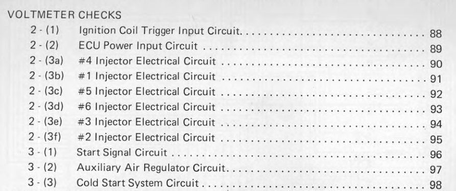
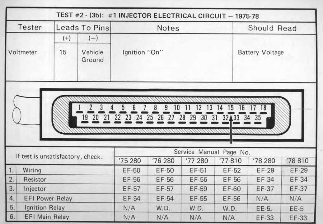
But you do bring up a good point about the grounding part of the circuit. You could have power but no ground. You can measure voltage at the ECU connector also. That will test the whole circuit. If you have voltage there then your theory about the ECU fits. Then you can get out your magnifying glass and check the trace back to the transistor.Did you disconnect all of the injectors before you measured voltage at the injector plug? And did you measure both pins of the injector plug? You are correct about power and the ECU grounds. But the ECU grounds several injectors at the same time, in two separate groups. If you left the other injectors plugged in and saw voltage on one pin it would be because the injectors are wired in parallel as CO explained long ago. You need to unplug all six injectors before checking for voltage. Actually, that should have been the first suggestion, before digging in to the dropping resistors. Unplug all six to break up the parallel circuit, turn on the key, and measure voltage at each pin of each injector plug. That will tell if #1 is getting power. You should see battery voltage on one pin of each plug.Looks like they are not color coded. So, your best bet is to unplug them all and confirm continuity for each power wire to each injector. Then check the wires in the dropping resistor itself if you find that all injectors have continuity. You'll have to remove the resistors for that. The problem would be either in the dropping resistor assembly itself or in the harness on the way to the injector plug. Edit - just noticed that #1 should come from the resistor with five wires. Just keep narrowing things down... If the drawing is correct you can even tell which pin is #1 by its position.
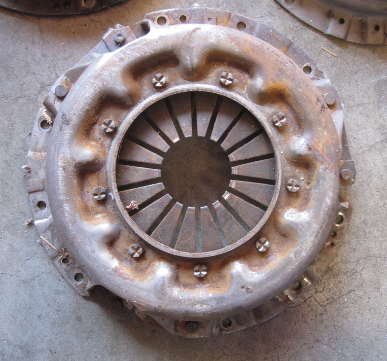
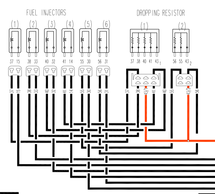 I would unplug the dropping resistors (you might be able to do it without removing the resistor, can't remember), then check continuity to the injector #1 plug from the resistor plug. I don't know if the wires at the dropping resistor are color coded or not.You're making good progress. You probably have a bad connection somewhere in the wiring harness. The most likely spot is at the dropping resistors, which are underneath and behind the washer fluid jug. Some screws hold them in. I would go there and take a look. That's where the power passes. You can check voltage in to the resistors at the plug too. Several injectors are fed through each resistor, so check each wire carefully. Edit, actually voltage in to the resistor would affect several injectors. Focus on voltage out.Cliff's method works. Another is the bolt pattern. Nissan did not drill theirs for both. 225 is 6 evenly spaced bolt holes, 240 is 3 sets of 3. 225 240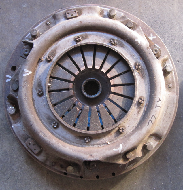
 Hey! 39 / 11 = 3.54. That's what all of the 280Z R200's are. I went through the whole thing of trying to take out only the parts I was working on when I first did my diff, prying and torqueing bits and pieces. It was a pain. If I recall correctly, I ended up later just removing the mustache bar end nuts and the front crossmember and dropping all three pieces down as an assembly. The mustache bar makes a good handle for balancing and you can just drop everything straight down. It works for assembly too.It does look more like injector alone. You can do a lot before swapping injectors. You can measure resistance across the pins. Should be about 2.5 ohms. You can connect a 9 volt battery across the terminals, with a fuel pressure gauge connected. You should hear it click and see pressure drop as the fuel is squirted in to the cylinder. You can put a noid light in the injector plug and see if it flashes while the engine is running. If you had a bad vacuum leak at the injector you might also get a lean misfire. You could check that by squirting starting fluid or carb cleaner at the injector gasket while the engine is running. Should get some fire then if there's a leak. That might explain why you're hearing the right noises and seeing sparks but not getting fire.I noticed on my engines that #1 seems to run lean, the plugs are always whiter than the others. I think it has to do with air flow, #1 must get more air. So if your system is tuned to the edge of lean, #1 might be too lean to fire at idle. Just a guess. You could adjust the idle air screw to richen things up. Screwing it in will divert more air past the vane, adding fuel. You could also pop the black cover and move the counterweight. The dead cylinder might be only happening at idle. That might explain why the plug porcelain is dark, indicating combustion at some time. A dead cylinder with a new plug should be "like-new" white.


Important Information
By using this site, you agree to our Privacy Policy and Guidelines. We have placed cookies on your device to help make this website better. You can adjust your cookie settings, otherwise we'll assume you're okay to continue.