zKars
Supporting Member
-
Joined
-
Last visited
Everything posted by zKars
-
Naw, flog it. I stuck 3 different shafts in the lathe and they all say 5-7 thou run out. Should have spent more on the lathe....
-
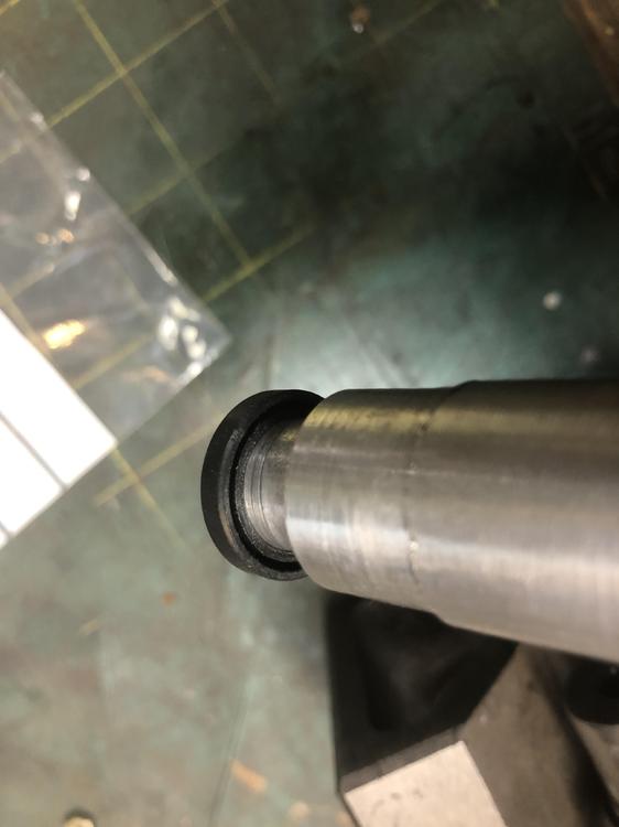
Nobody caught my booboo on the little seal. I installed it backwards. The fluid your trying to keep out should be on the open U shaped side of the seal, you would then see the flat closed side looking down into the shifter housing. I had just done the front cover plate seal, which you install with the open end of the seal outward, and my head for what ever reason said “ this seal too”. Not....
-
I scratched my head and finally at least have a clue why I can’t figure out what this. That fender badge says 280zx, so most here (including me) aren’t up on all the little hidden plastic body and fender bits and pieces. Does remind me of a mud flap like thingy
-
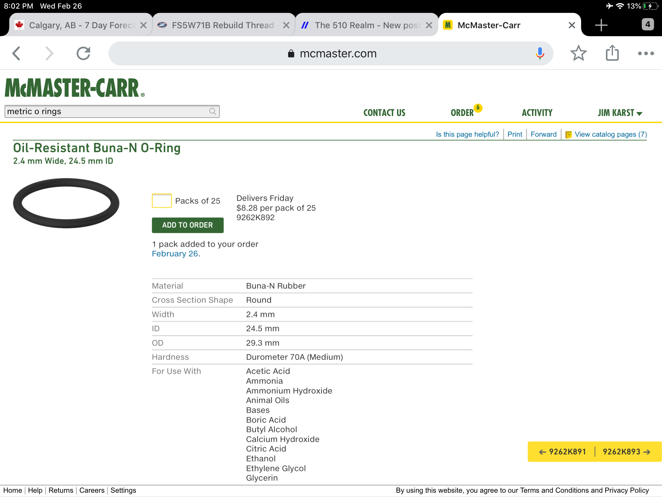
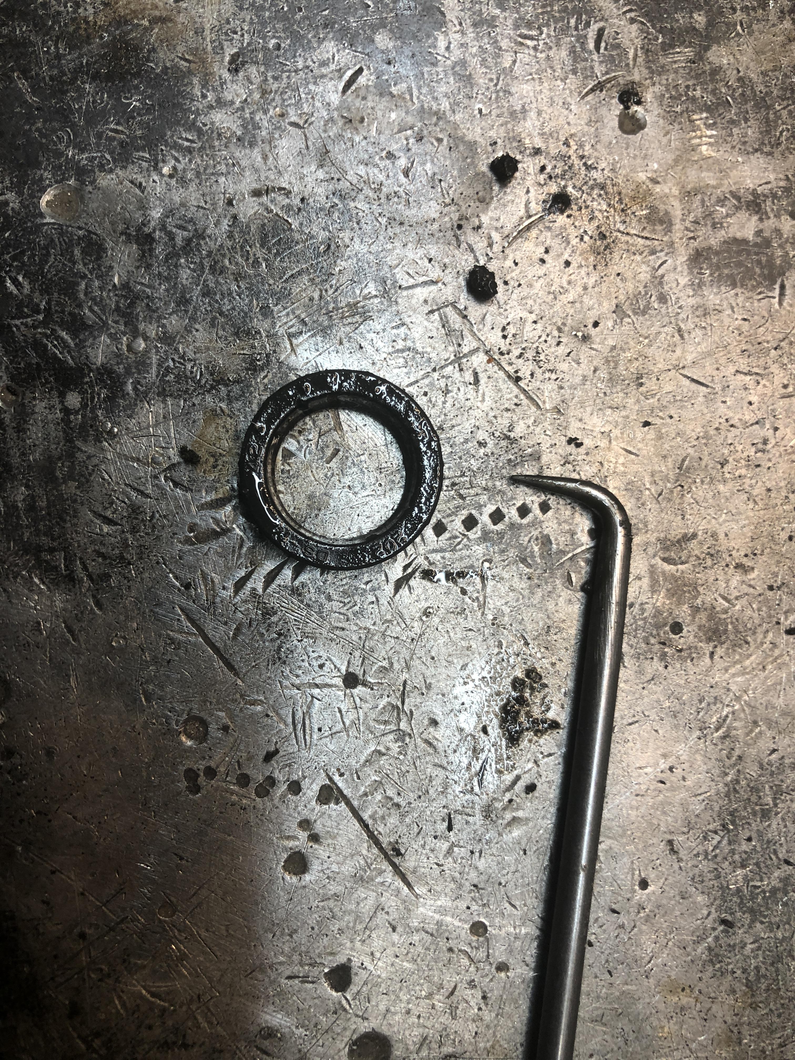
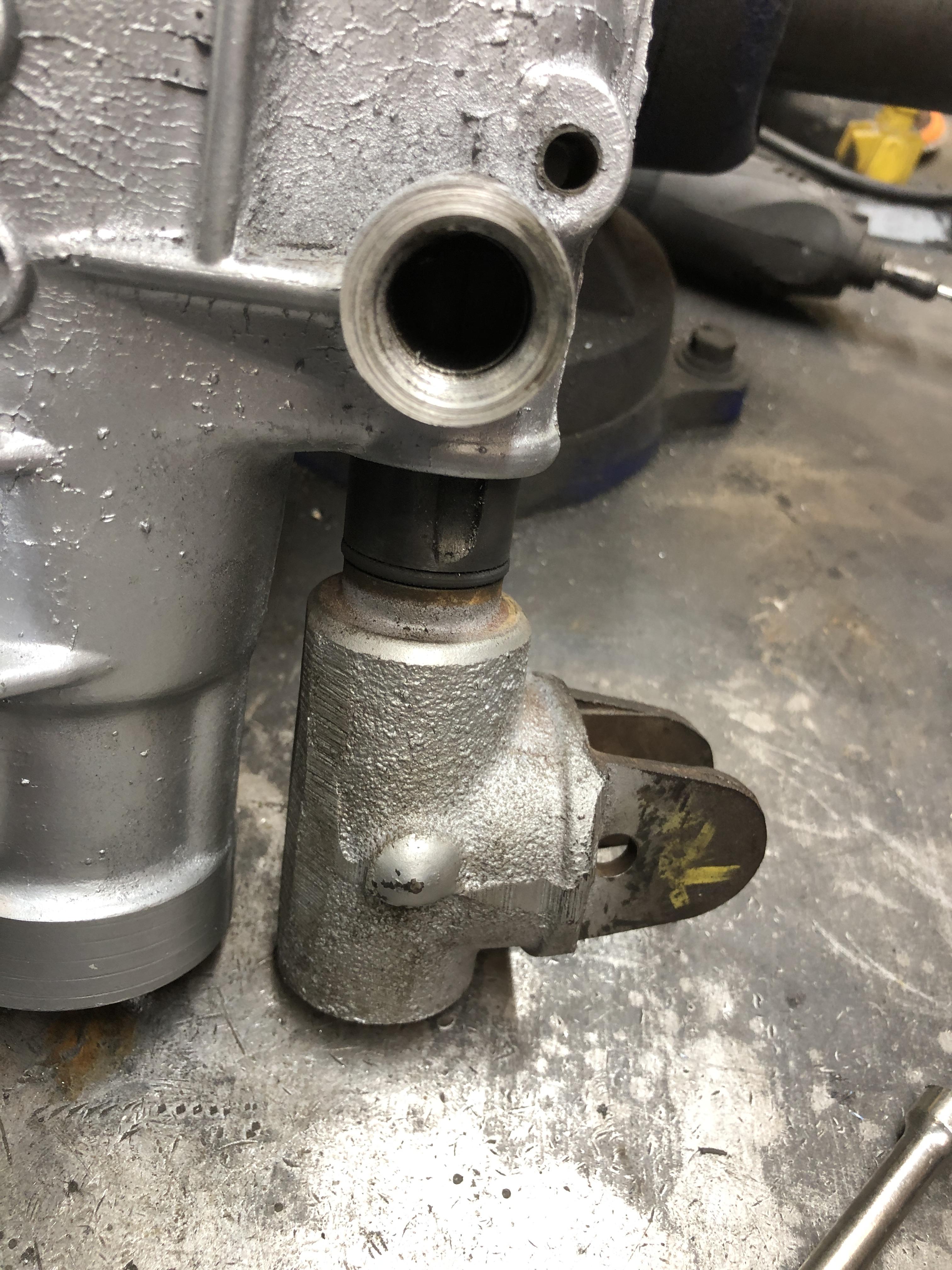
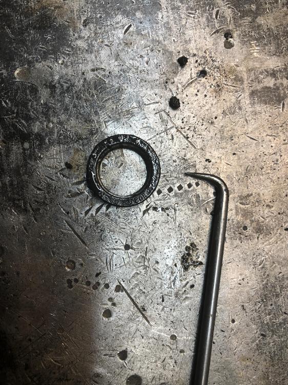
And finally The o-ring on the outside end of the shifter rod body. Somewhere it was noted that it’s the same as the one on the outside of the speedo cog. That is in fact true. The groove ID is 24mm, and it’s 2mm deep, and just over 3 mm wide. The o-rings I pulled off were 24mm ID by 2.4mm cross section. And magically a 15/16 or 7/8 x 3/32 o-ring fits just fine. The cross section is nearly identical and tiny stretch from 7/8 to 24mm does not deform the ring. I tested the fit into the speedo cog hole and they all felt identical in drag and insertion ease. McMaster Carr has a 24.3 x 2.4mm oring too if you can’t get a Nissan one and you want a really close equivalent.

-
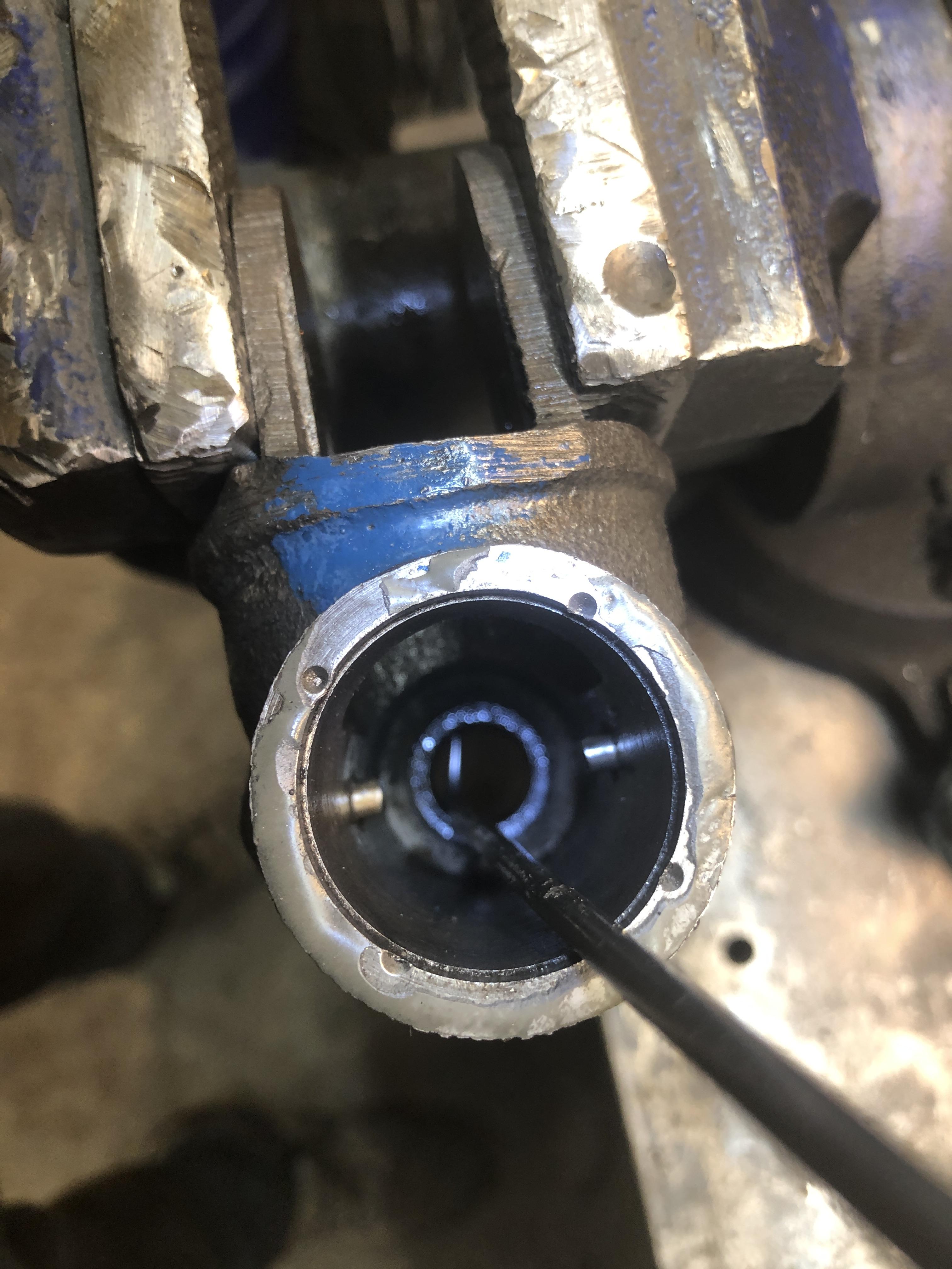
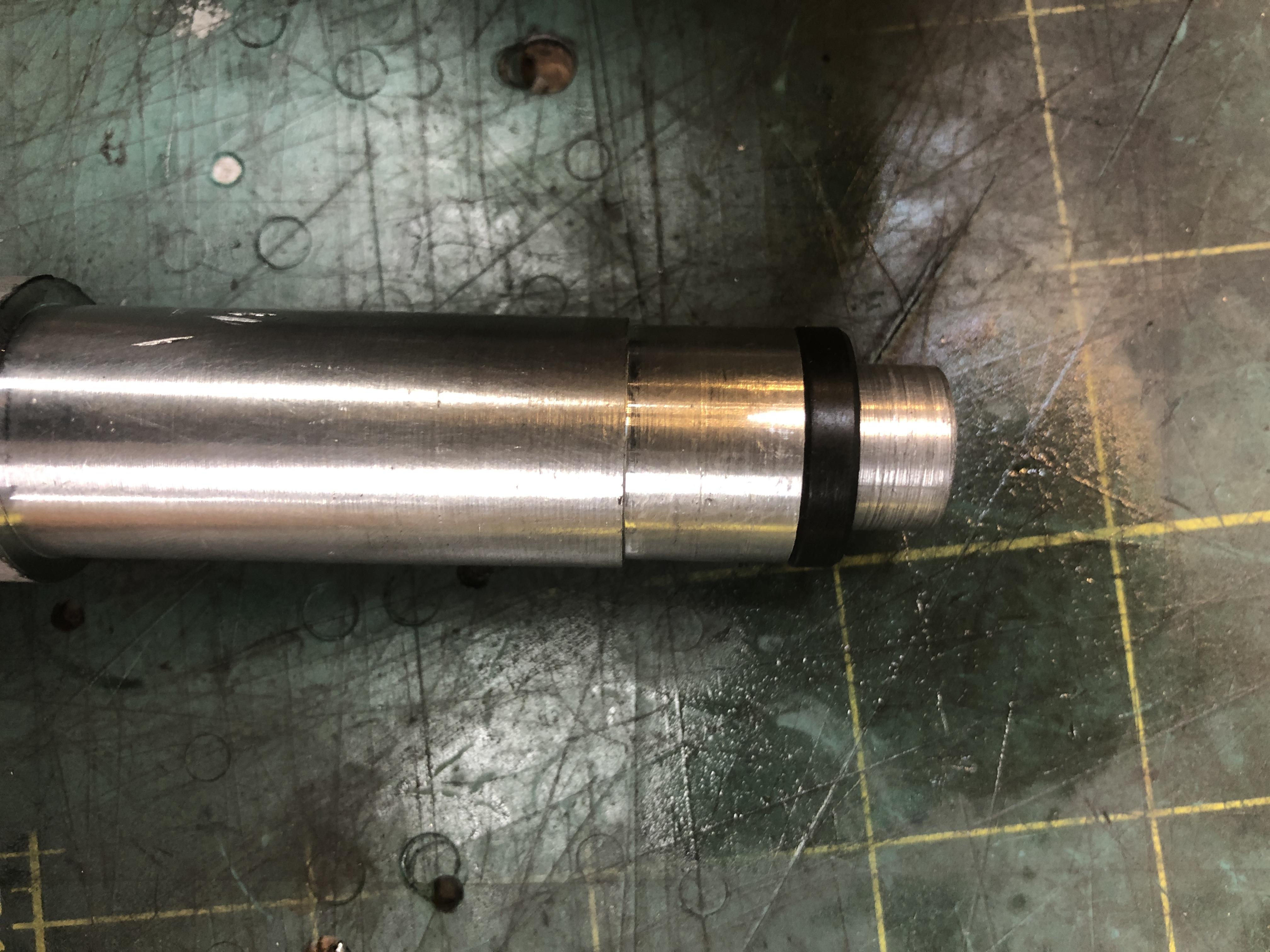
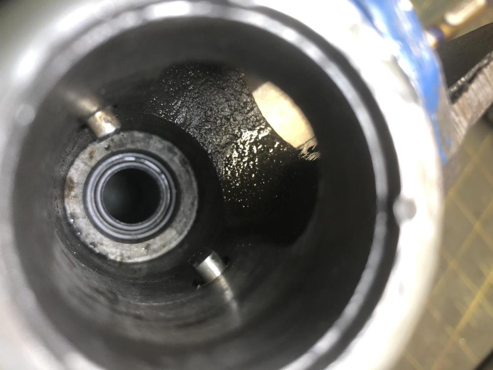
This transmission also has a leaking shifter shaft. The area where the shifter plugs in was always full of GL4 and causing a dribble on the floor. So I had a chance to try both my latest discoveries about removing that wedge pin to take the shifter rod out to change that little seal, AND how to remove and replace that little buried seal. Success on both cases. The air hammer gun popped the wedge pin out in 30 milliseconds again, and this time without any heat. I bought a set of really long seal picks, and that’s all it took to get that little seal out. You just need to put the tip of the 90 deg pick under the seal and YANK. And then to put it back in, I had no choice but to spend time on the lathe making a seal pusher-in-ner thingy. What other option would there be? Guess you could whack it with a 3/4” punch tip, but what fun is that. The specs are 13.9 OD on the seal ID part, 13mm long, then a section of 19.8 mm again 13 long. The nose guides into the hole, and the OD is just a tad smaller then the seal to push it home. The place it sits is about 1.5 times deeper than the width of the seal, so make sure it goes all the way to the bottom. I have no clue why the old seal leaked other than it was pretty hard and fit pretty loosely on the shaft. It was not damaged. Oh yeah, remember to put the dang thing in the right way. Oil is in FRONT of it, so when you insert it, with the open side to the back, against the insert tool.


-
Well now other than the need for a set of input shaft 4th gear set, I now need a main shaft too. I took apart the last of my good close ratio 5 speeds, in fact the one I’ve had rebuilt back 2008-9 and have had in my old 73 Z until its sale, and more lately in my 510. It was noisy in several gears, most noticeably in 3rd and 5th, and when you’re at a stop, foot off the clutch, you get a good rattly bearing noise. Other than that it worked perfectly. Upon disassembly, I noticed really only one problem. The forward end of the main shaft where the little needle bearing seats inside the back end of input shaft, is all scored up. And not evenly. When I put the shaft in the lathe, it seems to have about 5 thou run out. The needle bearing is quite loose on the shaft over the damaged area. These videos show the problem. Dang stroker torque bent the dang thing.... The 6 bearings look just fine, and spin silently. 84EDA2A5-E3BF-4942-B3D7-07C976AA7EB5.MOV EC2D0D51-2FEE-4A0C-A96B-F68E05F9A443.MOV
-
What I would have used, had I known it was M16 x 1.5, ?
-
Common misconception I believe. All the trans I've looked at have a 4th gear pair, just like any other gear. The only thing that is 'special' about the 4th gear set is that its ratio acts as a modifier to all the other gear set raw tooth pair ratios, since the drive power goes through the 4th gear set first, for all gears, all the time. It's only a matter of which of the lock up hubs (on each gear set) is engaged to the main shaft that determines the power path. The counter shaft is engaged and spinning all the time, and since all if its gears are engaged to the gears on the main shaft, THEY are spinning all the time too (except 5th), though they may all be free from the main shaft (if in neutral) or any one of them is engaged (and only one!), which then drives the main shaft at that gears ratio. The confusion comes because for 4th, it's special because when its main shaft gear is locked to the mainshaft, power goes straight through the main shaft WITHOUT first going down to the counter shaft (at the 4th gear ratio) then back up to the main shaft (through that gear's ratio) through the selected gear set. That's why its ratio is automatically 1:1 no matter what the 4th gear tooth ratio is. Hope that's clear as 25 year old GL-4 fluid.....
-
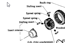
So I've been back in the transmission business again last couple of days. Mostly trying to assemble all the carcasses I have laying around here with new bearings and syncro's to get at least the clusters together. The first I one I completed today is the one that had the very very failed counter shaft intermediate bearing. About the only thing I found that was also "Wrong" with it was the needle shell bearing under the 1st gear on the main shaft that was very very loose. I went to put it back on, and it was rattly loose. Couldn't see any damage, just worn I guess, so grabbed one of the old ones from another trans and it slipped on nice and tight. Didn't buy many new spares. There was also a strange bit of damage I can't explain. You know that "Insert Retainer" on the main shaft on the back of the intermediate plate? The thing with the three fingers? Always makes me think it's home made the way it looks and fits. Three little tabs of metal welded onto a tube. Locks the 5th gear syncro gear to the shaft. Anyway. Yeah, well one on fingers was bent. Toward the back. Couldn't make the shifting insert fit back in at that spot. Must have been an errant bearing cage piece got caught in there somewhere when the bearing just below it went KABLOOOWEEEE. It's quite buried, not sticking out or anything. Glad I caught it. Then moved on tranny #2. This was the one with worn out 1/2 shift fork. Now old bright boy here stole its 4th gear set to build up that truck 5 sp I have with the custom ratio's I detailed earlier, that give me the .68 OD. Wonderful. Unfortunately, if I put the the truck 4th gear set in this tranny, I get stupid ratios, like a 0.9 OD. So now I'm kinda stuck. So now the interesting part. Anyone have a busted 5 speed they kept around for parts, that they are willing to maybe give up their counter gear cluster and the matching main input shaft nose part with the 4th gear on it? Otherwise I have a really nice Close ratio 5 speed without 4 gear..... or any gear actually.... Along these lines, anyone ever see a listing that gives the tooth count of the counter cluster and main shaft gears for the common FS5*71 trans? There are a million places that list the final drive ratios, but not the internal tooth counts. I know the tooth count for the late ZX ones, (got lots of those open), but not the 79-80 and the earlier 77-78 280z. Need to know what their 4th gear tooth counts are to see what the final ratio's compute out to, should I procure some parts from those types...
-
I really think if your nut threads on just fine, there is no reason to not reuse it. To ensure the staked section ends up in a new spot, make a thin spacer from some brass or thin steel stock. I’ve got a method of releasing the original stake without harming the metal or breaking it. The nut metal is surprisingly soft. In fact I have been successful twice now by simply undoing the nut WITHOUT doing ANYTHING to remove or push up the staked part of the nut! It just gets pushed up as it engages the threads. That 2 ft long 1-1/2 wrench makes it easy to twist that sucker right off. Of course you’re all cringing, “how dare you risk buggering up the precious threads on the shaft, you monster!” But in every case so far, there has been 0 effect on the threads. The shaft/thread metal is about 15 times (professional estimate...) harder than the nut. Then when I put the nut back on and torque it down, I just re-stake in the same spot. Yes after a couple of these I’m sure the staked area will fatigue and break out. Then do the spacer thing to move the stake location. Regarding the reverse switch, Every one I’ve ever taken out hasn’t had an oring or copper crush ring, and new ones I’ve purchased don’t come with them, including Nissan ones. Just clean it and the case where it seats and snug it down. If it leaks, use a thin crush aluminum or copper washer crush washer or a dab of gasket maker goo. Don’t add too much thickness or you may cause the switch tip to not contact the shift rod and render it intermittent or inoperable.
-
The temp sensor is a straight thread, not a tapered pipe thread. The temp sensor is a two part deal like a brake fitting. Finding an adapter will be a trick. I feel quite bad not knowing the thread spec off by heart....
-
-
-
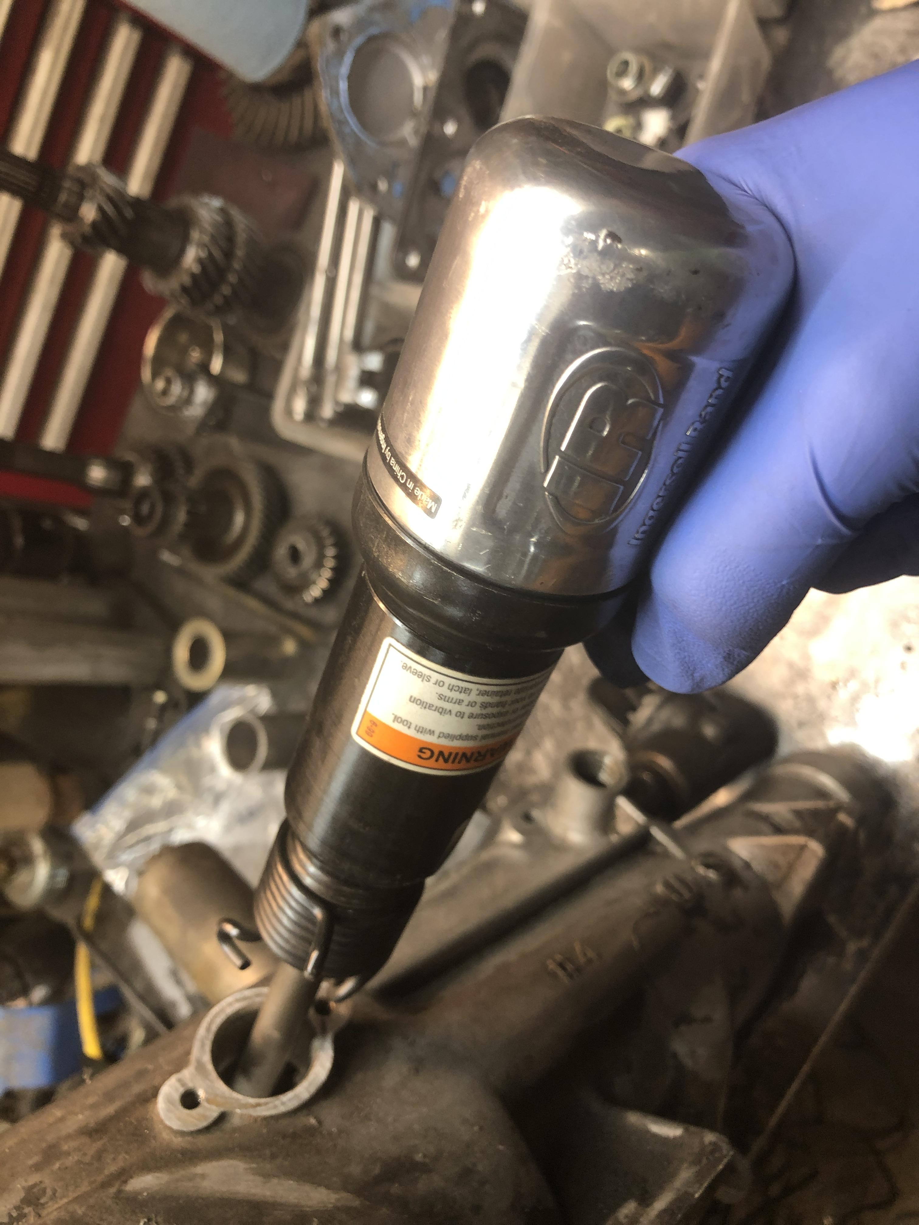
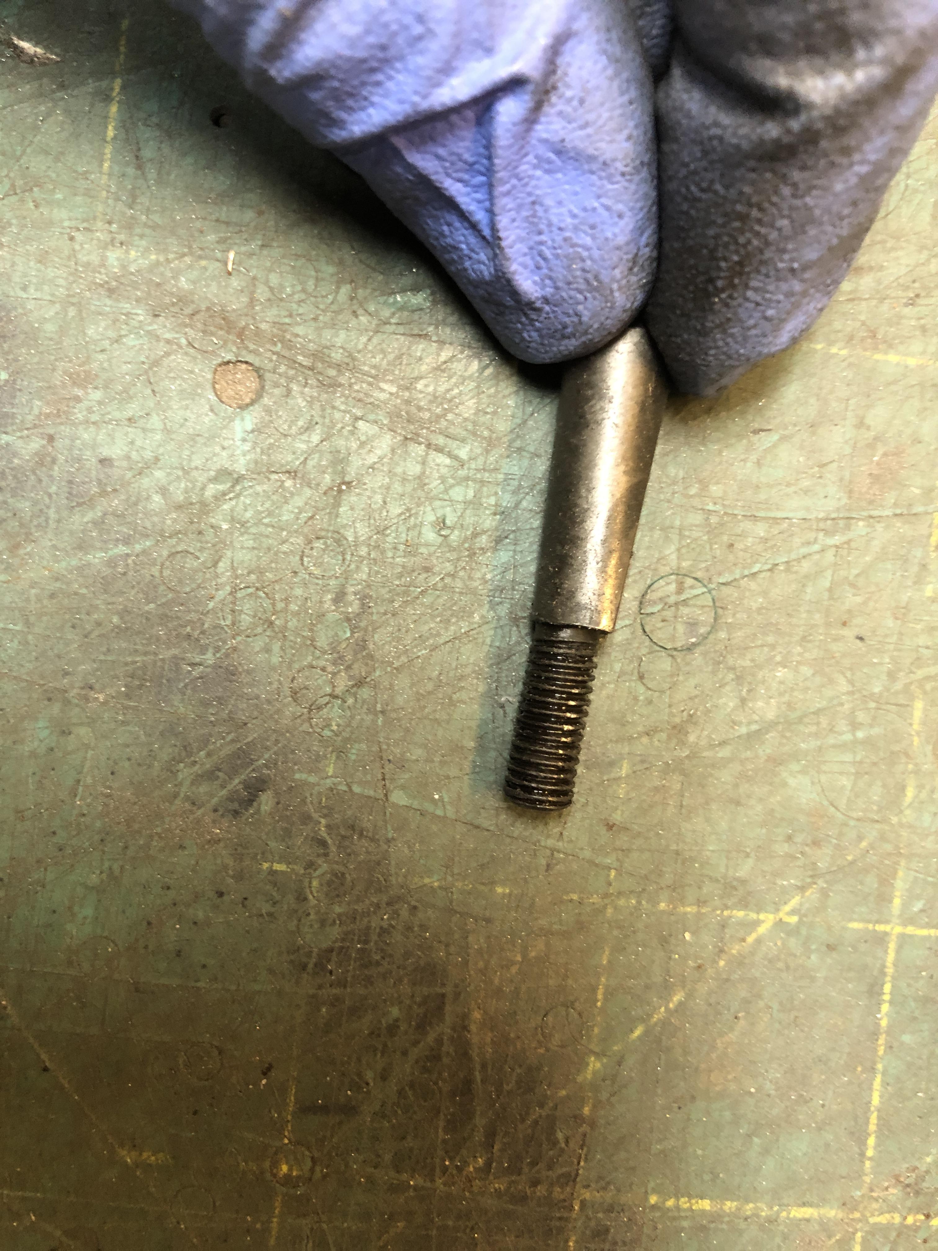
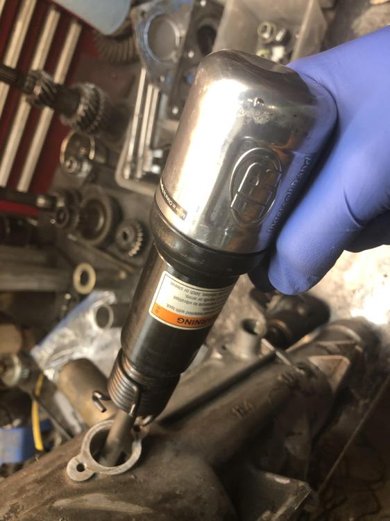
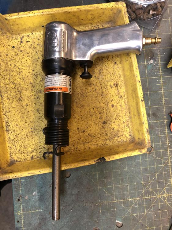
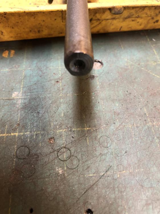
Well I tried my fancy azz press tool on a “fresh” tail housing pin. Not quite perfected. It was not pushing dead straight and the threaded portion began to bend. Quite happy it didn’t snap. resorted to more heat and a punch with the fancy azz new support tube/angle iron. Still no joy. Still too much bounce in the system. Decided to try the air hammer. Machined one of the tips with a flat and 1/4 hole to catch the end of the bolt. Well I have to tell you, it popped free in about 2 milliseconds of pounding. I suppose I had loosened it up a bit with previous attempts. Let’s just say that’s true... For me, the right thing to do is to just use the dang air hammer, making that hole in the side of the case first if you have to, and plugging later. Having decent backup, even a chunk of wood wedged in there, would be plenty.

-
Aha! PM=Personal message. Click on my screen name, zKars, then when the new window opens, find the message button. Click it and type your message. That way we can discuss details without polluting the thread.
-
I can fix you up. Send me a PM.
-
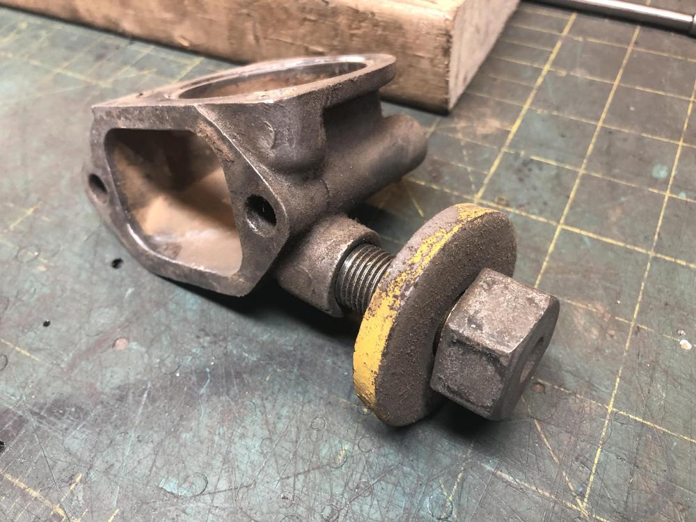
That’s a new one on me. Looks like that main shaft nut has been off and replaced at least once. Looks like a spot weld has been added...
-
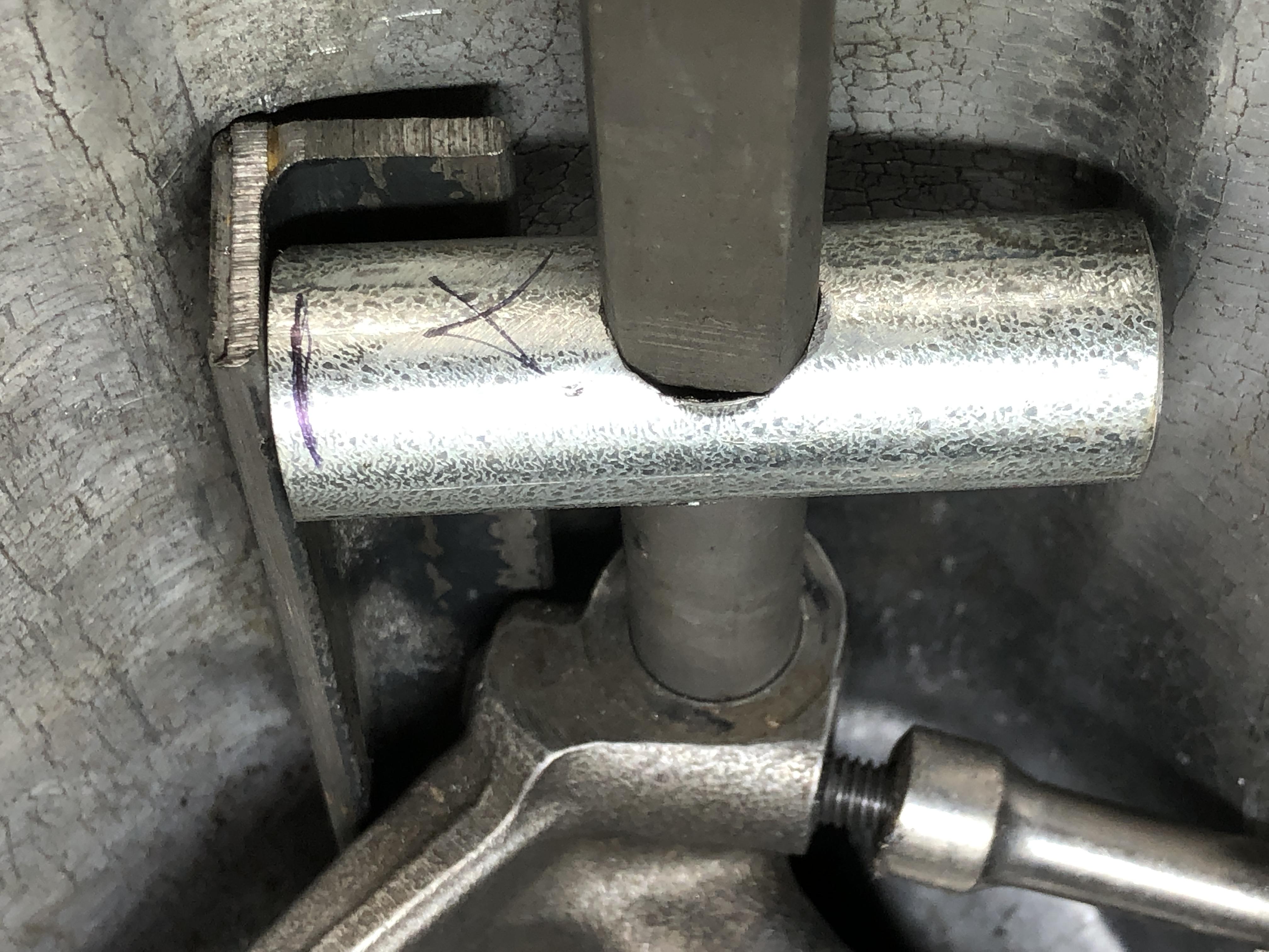
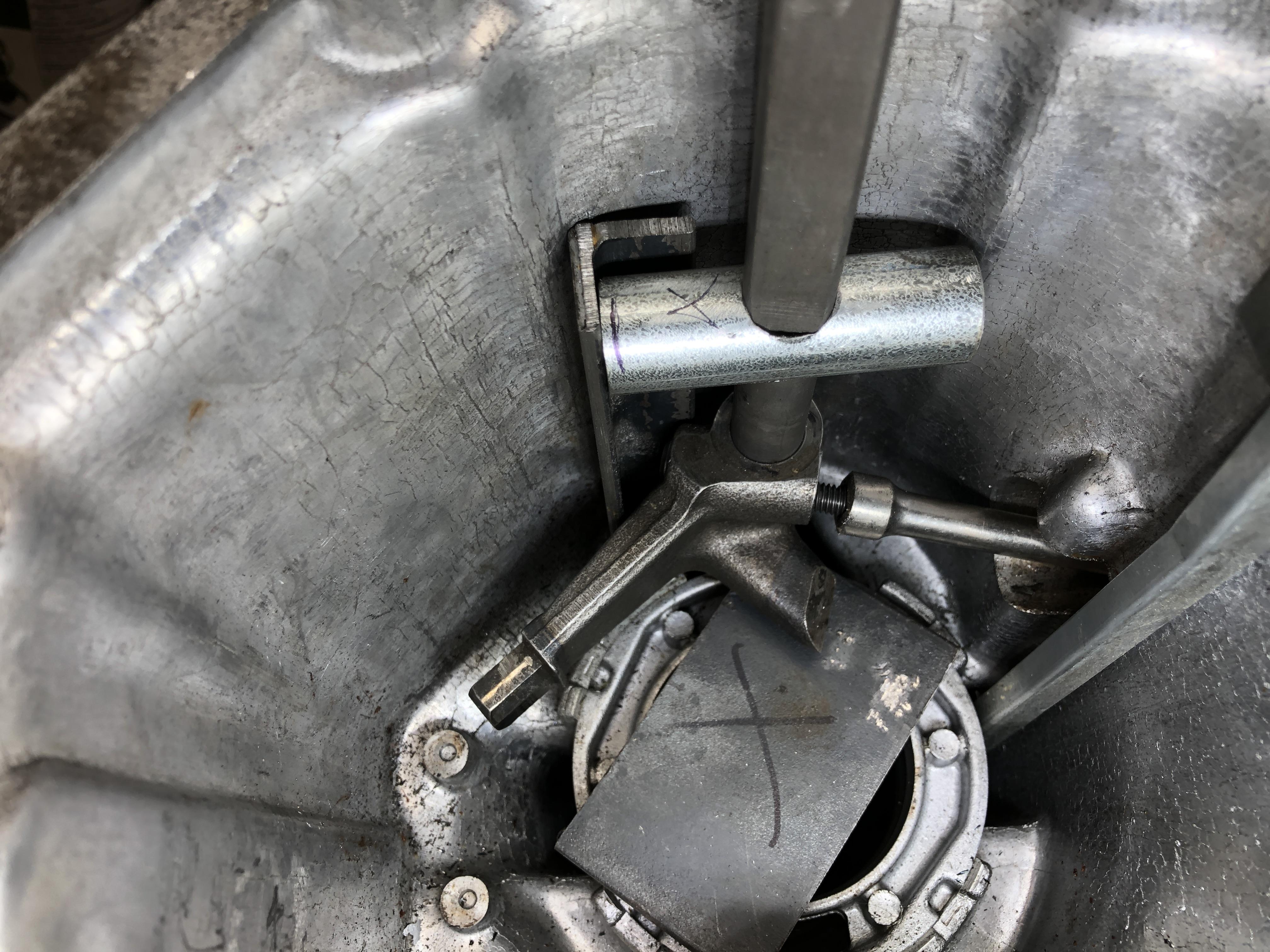
So here is a simple solution to the shaft support issue while whacking. The pipe is a chunk 1/2” electrical conduit with a 17/32 hole (perfect fit on the shift rod BTW), 1” from the edge. The pipe is 0.8” diameter. It butts up against the 3/4” angle iron real nice. You could drill a 1/2 hole and file it out to 17/32” to save buying that bit. I have more pipe on the right than you need. The “punch” is nice and straight on the wedge bolt (its dangling free in the pic, ie not straight) and more or less in the center of the reverse lockout hole. Note that the 1/4 extension has the end cut off some to make sure it traps the end of the bolt, but leaves enough exposed to let it move when you hit it. That’s a 3/8 plate spacing the shift casting off the bottom. Helps keep things in place while you place the angle iron and pipe. The rear shaft pin is out of the casting, and the other guide/spring are out as well to all the shaft components to move in and out and rotate to get everything lined up.


-
If it weren't 6 inches down a 1" hole.....
-
Thanks for that, I wasn’t clear. I have the rod out via the tap it through the end cap idea, and I now see the seal inside the bore. How to remove that seal? I can think of some crude ways.... What has worked for people?
-
Air hammer would work too. Have to find one that hits 90 degrees at the tip to make it work on cases without the reverse lockout hole. And can someone give me a bright idea on removing that inner grease seal that the shift rod passes through? There’s a dang metal ridge right behind it that prevents a punch from reaching it. Some kind of hook from the front? Going to have to invent a punch/holder thingy to re-insert it without hurting it too. Will this transmission challenge ever end?
-
Aha! Push the tip of the wedge bolt using the case opposite as the base. If you can get it to seat nice and tight against the case where it can’t slip, this could work. There is lots of rotation so you could find the spot where the case surface is orthogonal to the turnbuckle axis, or a ridge to catch against. Would need to find a good quality turnbuckle with fine threads. Naw, just make one. Drilling holes and making threads is basic work. And yes, the backside would need to be well supported just like the “whacking it out with a pin punch“ case. I think I have a better solution for that too than a chuck of angle iron crudely propped behind it. Something that slips over the shaft and has a threaded bolt in it that you unthread until the bolt head touches the case. Probably still easier to drill the hole, whack it, then plug the hole. But not as much fun!
-
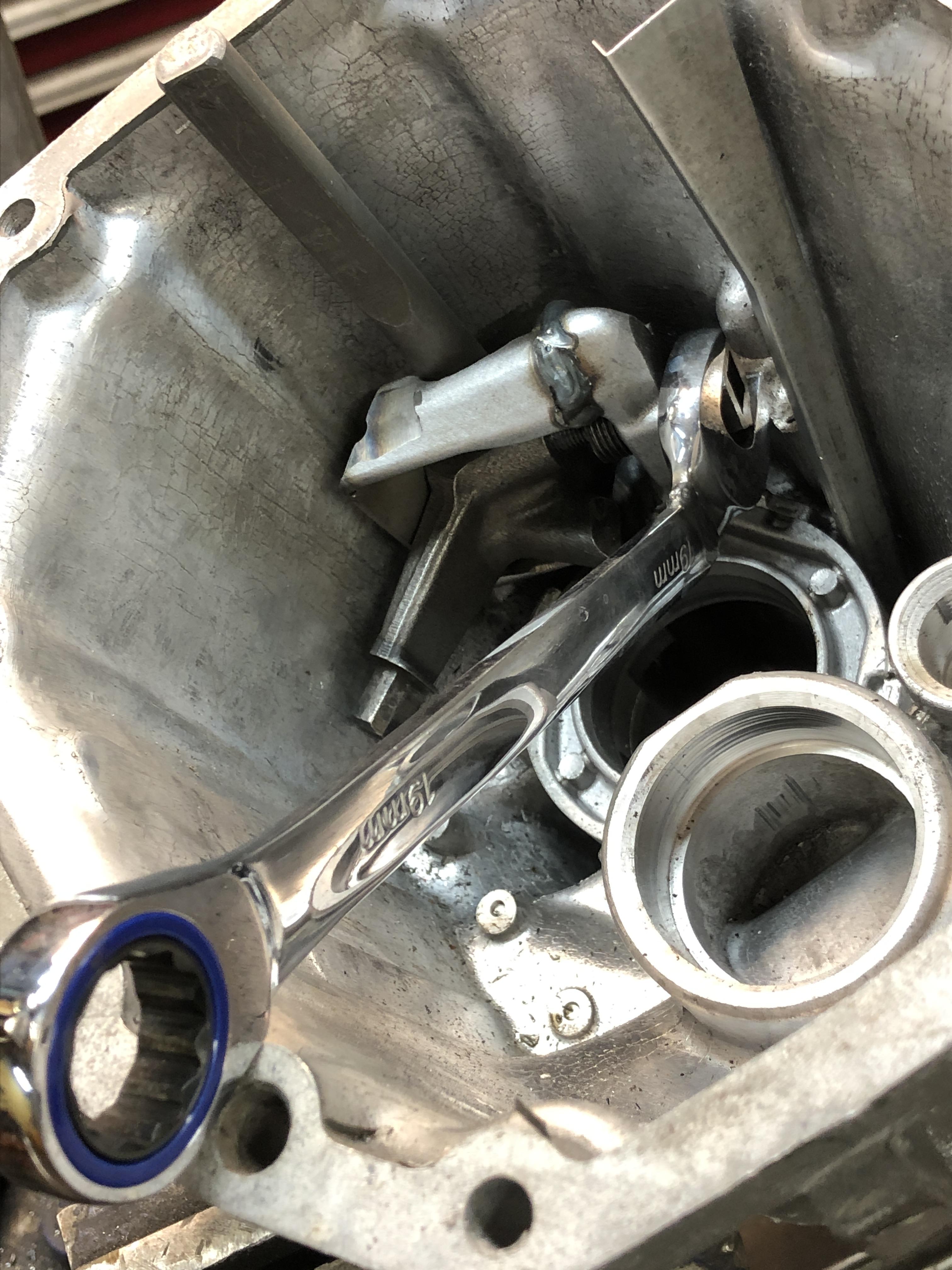
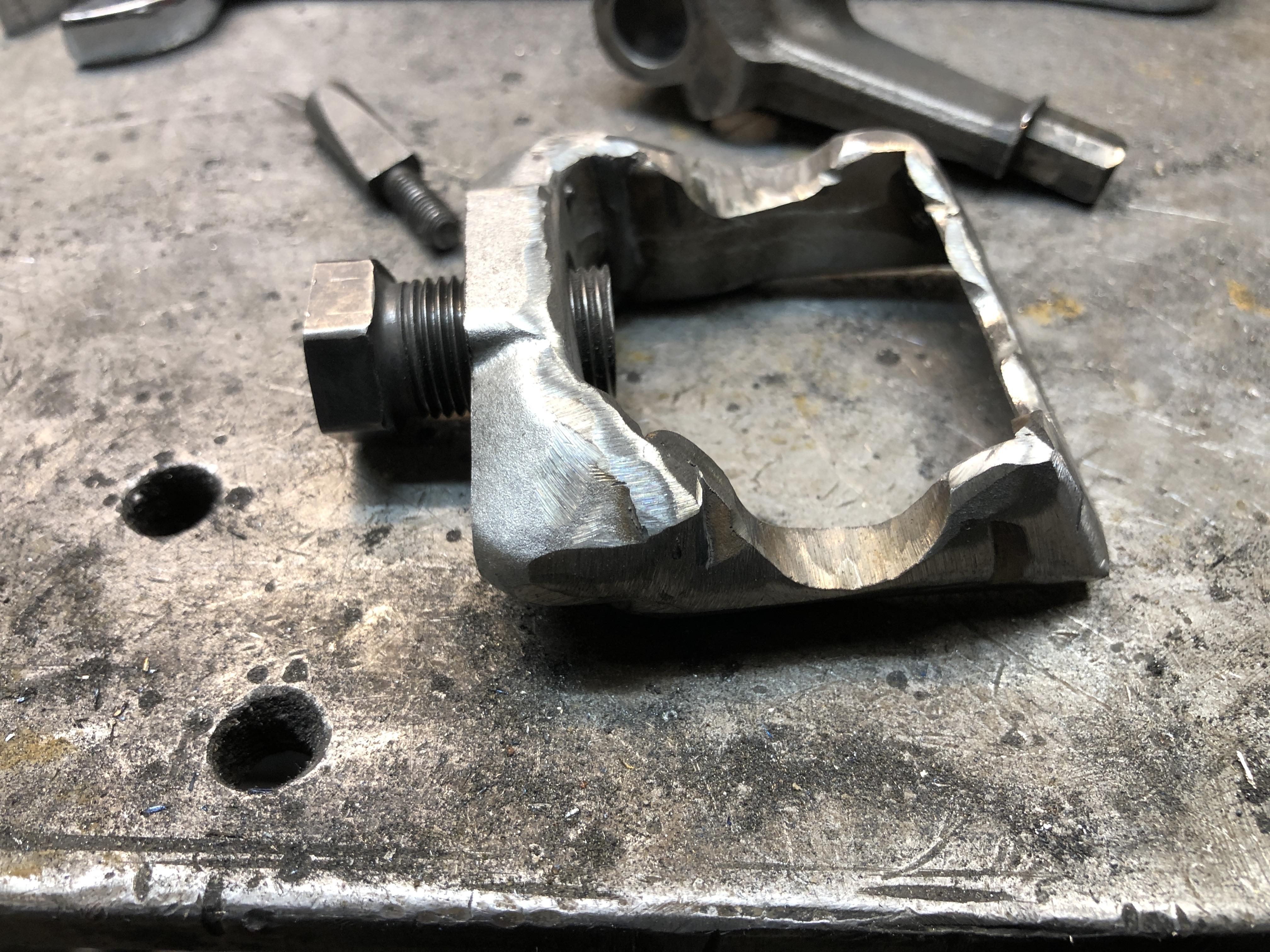
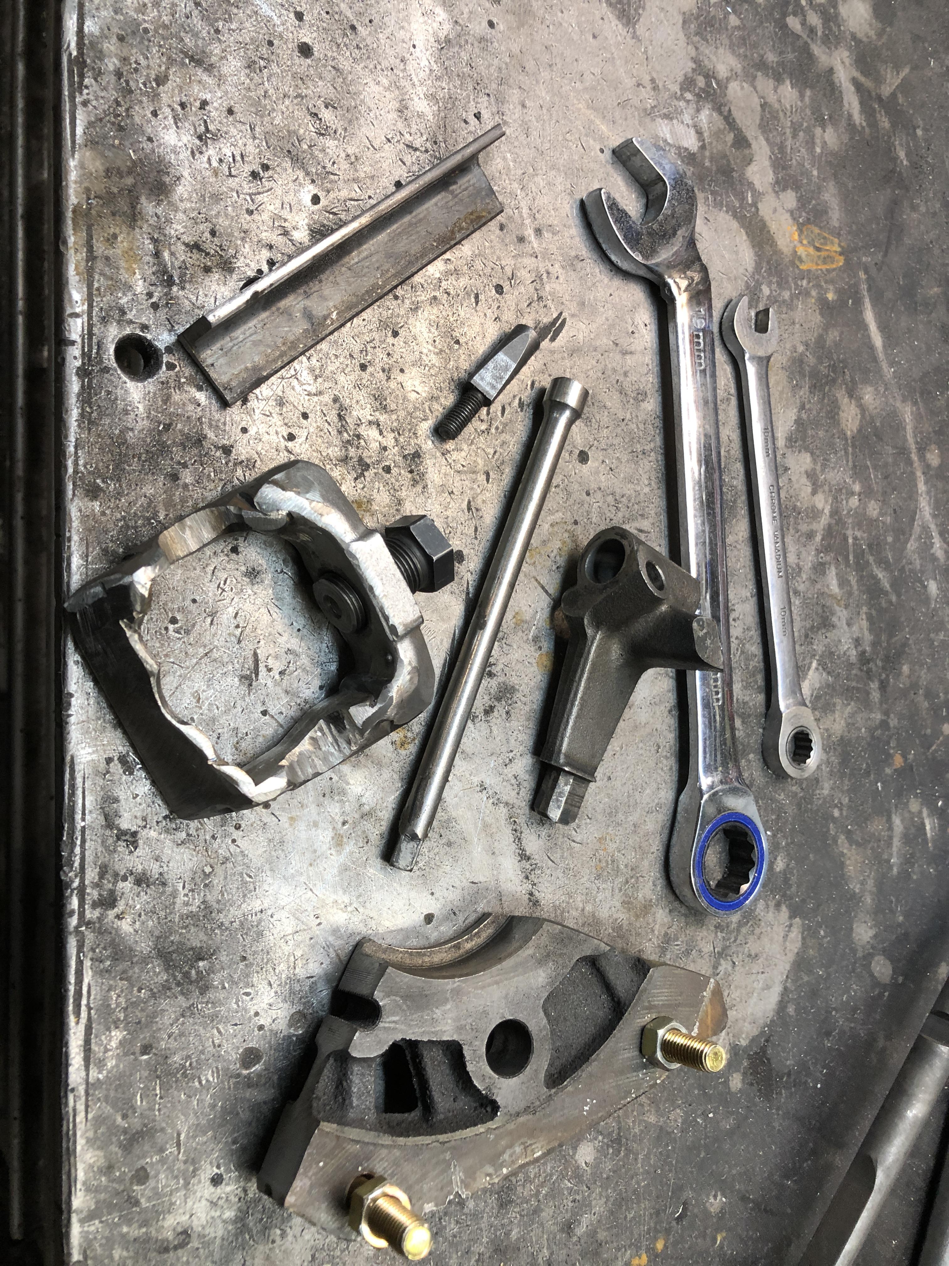
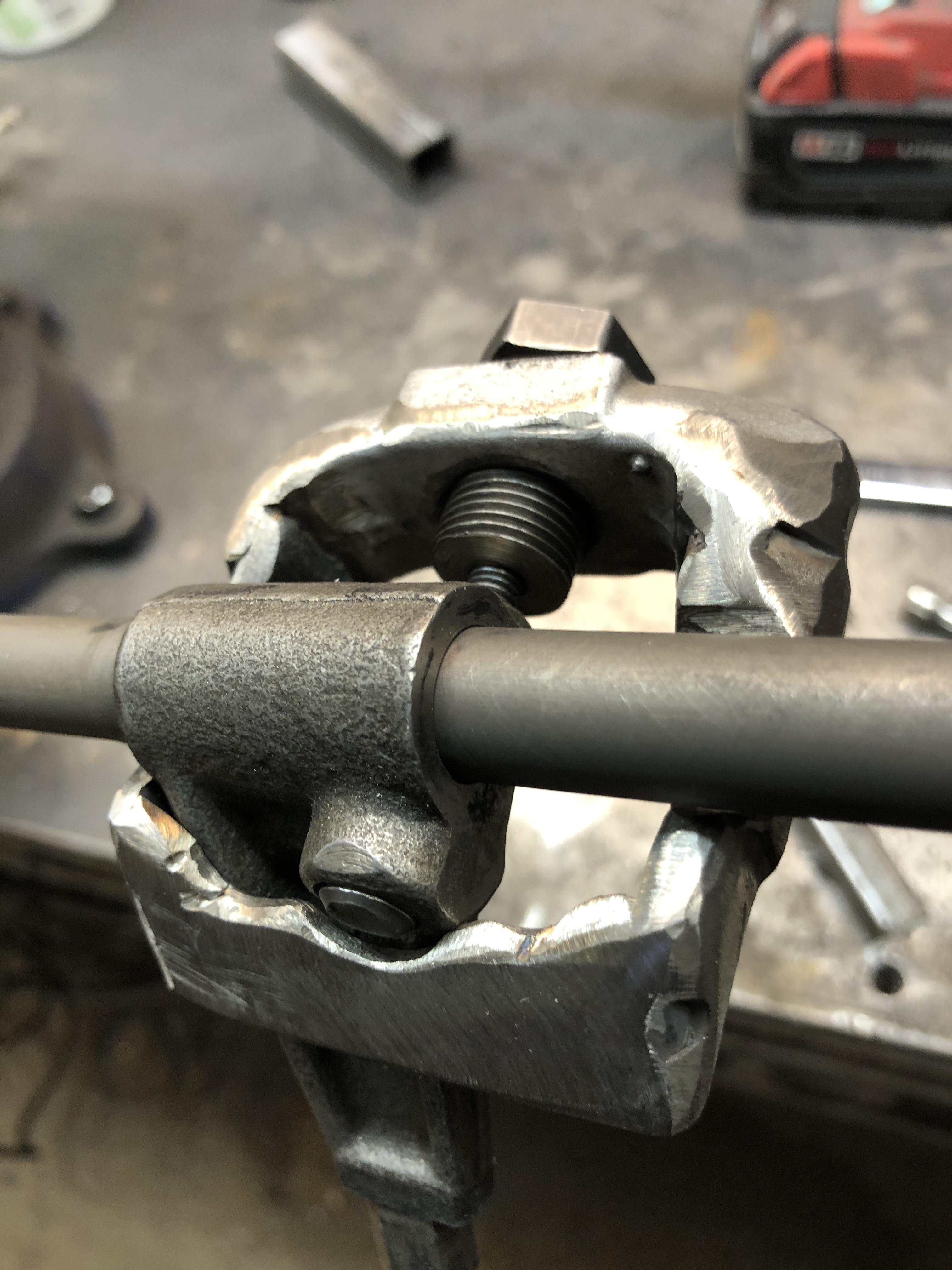
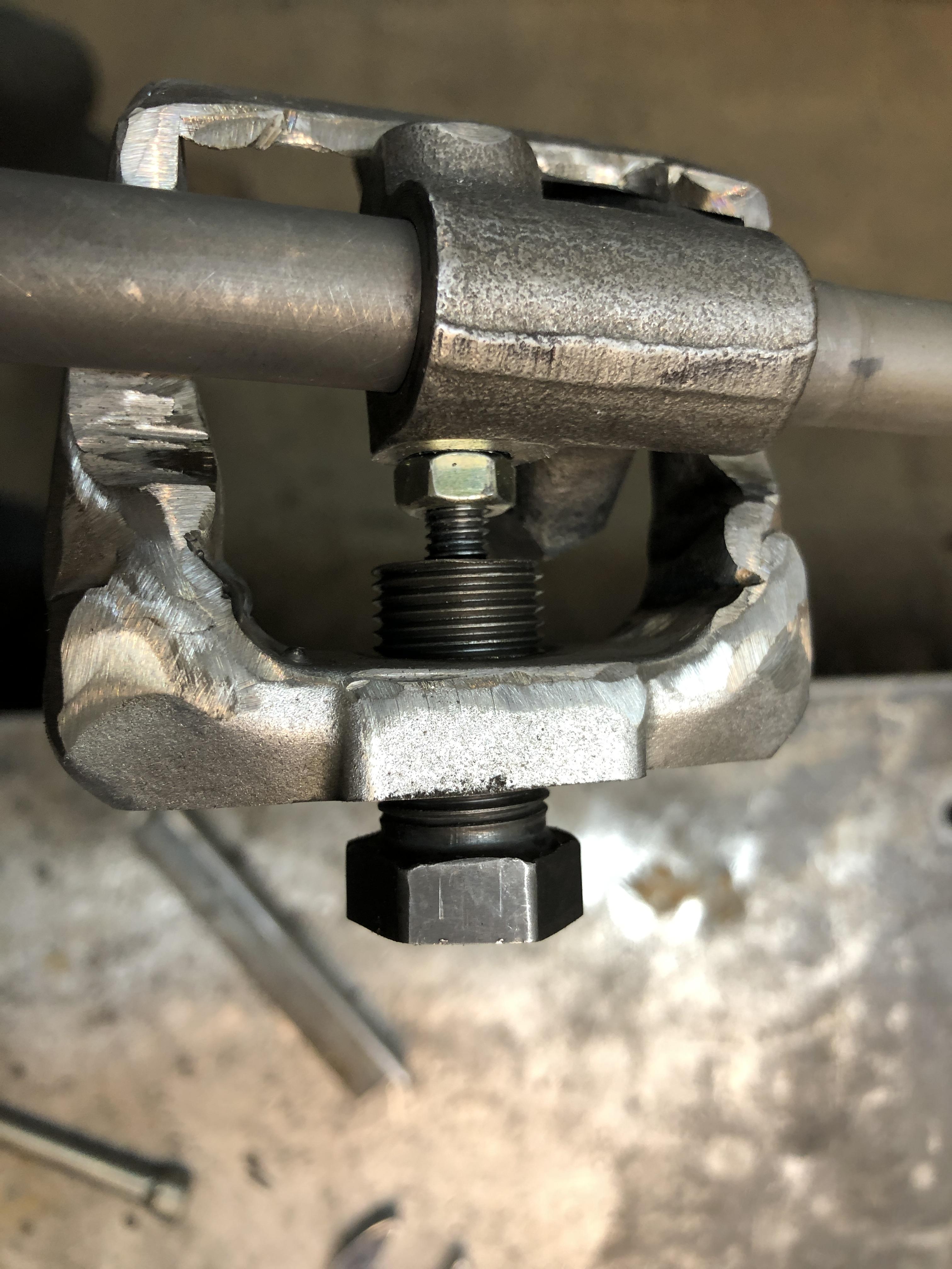
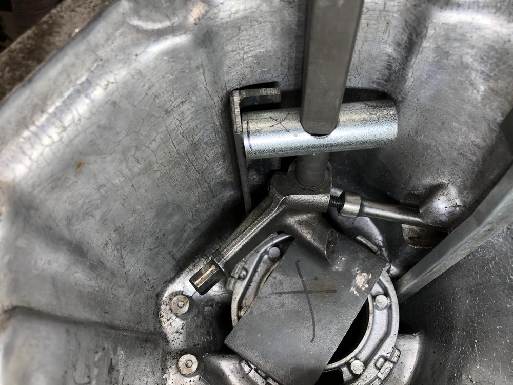
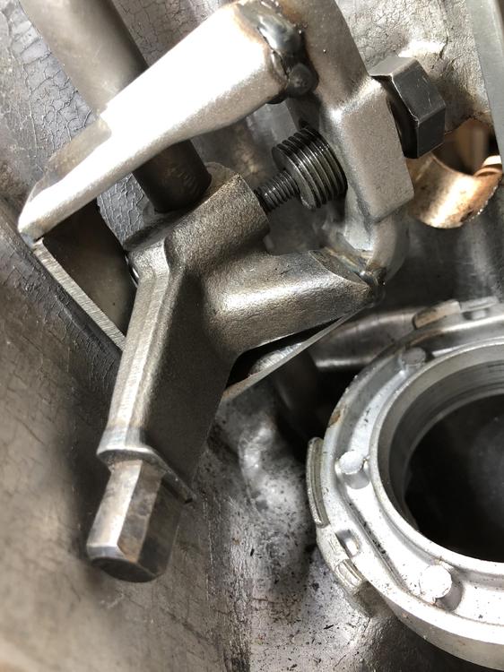
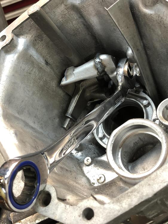
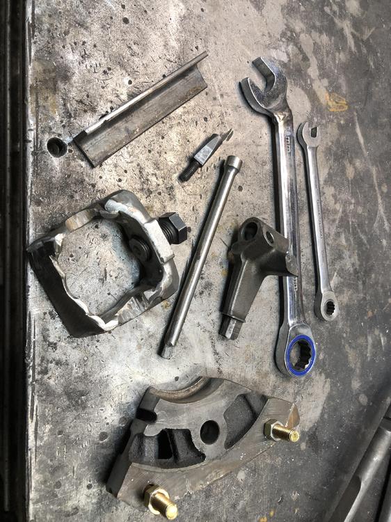
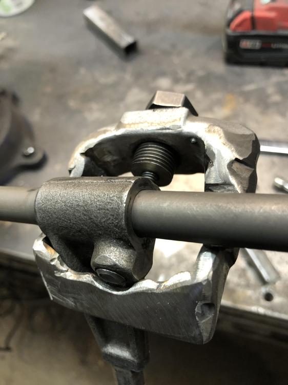
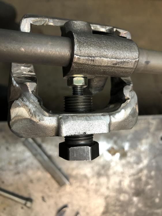
Ok, here is the beast. Bit rough, it has been through many changes on the way to a working model. Here is how it fits and sits on and around the rod and lever arm. And here is it in action inside the tail housing/ The nut on the threaded pusher is 19mm, so had to make a custom bend on this 19mm open end wrench to allow access and at least 1/6 turn. The nut is very close to the raised casting area around the reverse lockout assembly hole in the case. Had to get the length of this pusher bolt just right to allow you to put it on the wedge bolt tip and still get you enough room to push it off. The tail housing without this reverse lockout thingy would have much more room. You might even get a box end wrench on it. Here is the SFT’s for the project The bottom chunk is the part of an intermediate plate from a junked 4 speed. It has the hole for the end of the shift rod. Helps to keep the shift rod supported if you using the 1/4 socket extension whacking method to remove the wedge pin. I still needed a firm support behind the wedge pin area to the case to prevent the rod from just flexing when you hit with the sledge. That is what the 3/4” wide 1/8 thick angle iron piece does. Sits in there real nice. Design wise, the biggest change I had to make to the original tie rod end puller was to cut the legs off close to the threaded end and shift the whole body down about 3/16” then re-weld. This is due to the fact that the wedge pin sit below the centerline of the shift rod by about that much. Your threaded pusher bolt has to be in-line with wedge bolt or you risk bending, well actually, snapping it off. You will be applying considerable compression on that little M6 threaded pin.The 1/4 hole in the end of the pusher bolt makes sure the pin end stays straight and engaged. Now the real test is to try it on fresh untouched pin in another housing. This test pin was never re-inserted with the same pressure as it had from the factory. At least there was zero, and I mean zero signs of rust or pitting, or roughness on the pin. Being bathed in oil its whole lift kept this one clean. If you have a wet rusty one, you’re in for a fight. Heat, penetrating oil, time, the usual.... I still think the “best” approach is to use the pin punch (1/4” socket extension) from outside the case through a hole. Easy on a trans with the reverse lockout, but you’d have to make a hole in the same spot for the earlier ones. I don’t think this such a big deal. We have the exact location from any trans with the reverse lockout, and making NPT threads and plugging it is pretty benign. 1/4 or 3/8 NPT is a plenty big hole. Or you spend a day or two making a custom puller. Your choice.

-
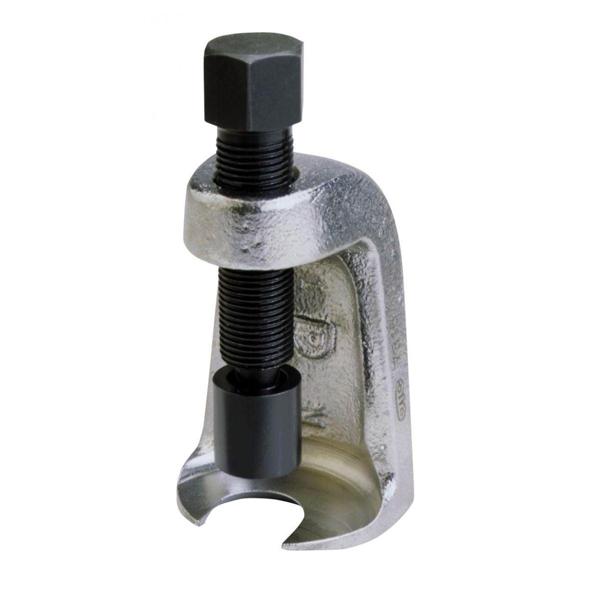
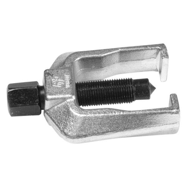
I’ve been slaving on a proto type. Room is tight in there, but I have something that seems to work. Lots of trial and error. Yes a welder was required, cut off wheels, carbide bit in a die grinder, used a lathe but you don’t “need” to (to make a nice centered hole in the end of the threaded press screw) Started out as one of these. Pictures of the final thing in action coming. I used a tail housing from a late zx trans with the reverse lock out thingy, so getting the pin out initially to have an assembly to play with was easy. As long as you support the shift finger casting on the shaft very solidly against the inside of the housing, you can smack the end of the pin with the female end of a 1/4 drive 6” socket extension (so it stays on the end of the pin) with a 3 lb hammer and it pops right out. Any amount of bounce in that shaft and you’re banging on a loosing proposition. I used 1 minute of propane heat on it first.
-
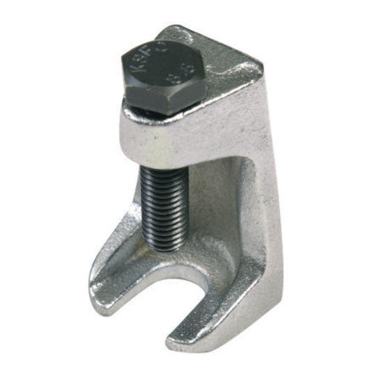
I’m imagining a tool to make this easier. Imagine a forked body that hooks over the shaft, each side of the bolt, and a threaded bolt like thing that presses on the end of the stud to push it through. kinda like this tie rod ball end remover thingy, but with bigger better wrap around fingers spaced further apart. Nice cupped end that snuggles over the threaded end of the stud to keep it on. Gonna go ‘play’ tonight and see if I can make one.