Leaderboard
-
Patcon
Supporting Member3Points11,279Posts -
conedodger
Community Member3Points13,006Posts -
Namerow
Community Member2Points1,573Posts -
HS30-H
Supporting Member1Points5,558Posts


Popular Content
Showing content with the highest reputation on 08/16/2025 in all areas
-
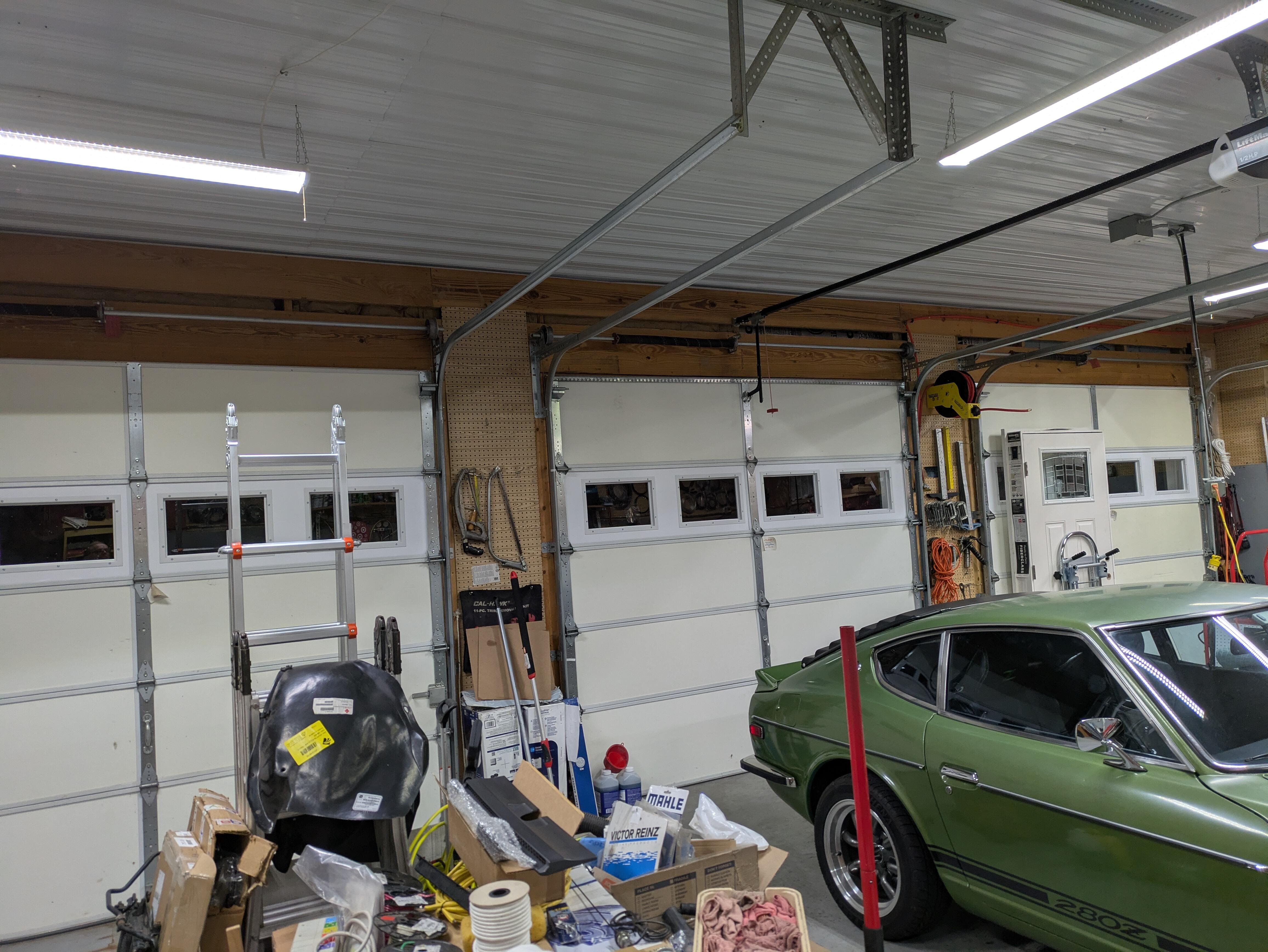
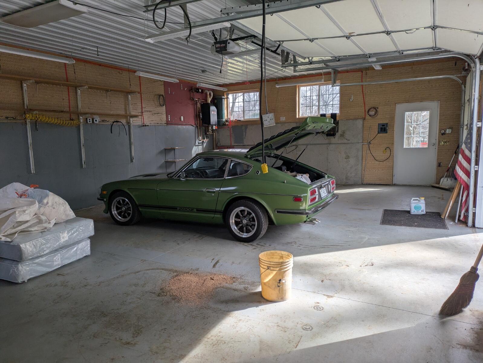
Even though you put a ton of work into fixing up your old garage, I guess it wasn't too difficult to leave it behind in return for a clean, modern garage already equipped with a good floor, good lighting and three bays (not to mention a separate, two-level barn for storing panels and parts. 👍1 point
-
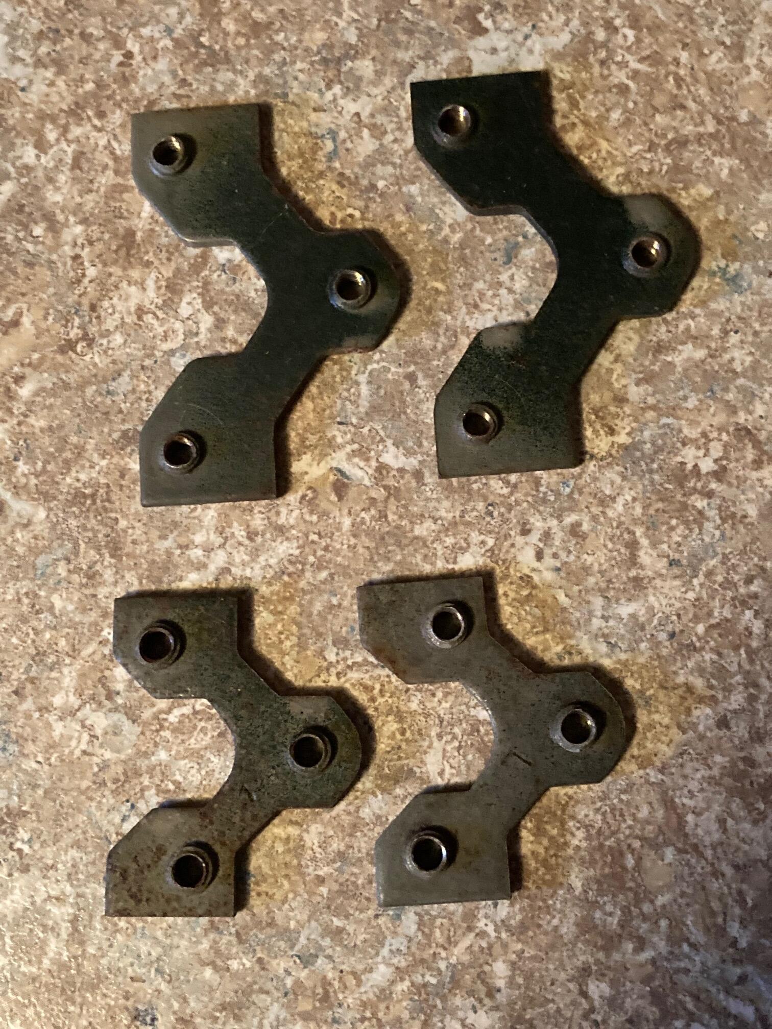
1 pointThey have a hinge mount plate on the inside that will fall when the bolts are removed.
 1 point
 -
1 point
-
Thanks, Yarb. I am on hybridz too, I joined it when I started exploring the Megasquirt/turbo upgrade (I was getting fed up with the AFM/running lean etc lol). There is less traffic now as it used to be.1 point
-
Glad to see you back.1 point
-
The reference points used to generate that 913mm measurement are tricky to replicate in practice. If you look closely at the small sectional drawing of the front shock tower, you'll see that the 'A' point actually lies on the plane defined by the underside of the shock tower cap. You can't measure at this plane unless you remove both front struts and then use either a trammel bar or a plumb laser. So, instead, you have to measure across the tops of the shock tower caps. But... Not so apparent from the sectional drawing, but very clear to the naked eye, is that the shock tower cap has a lip on the top (this is a little more evident in the sectional drawing of the rear shock tower that appears on the right side of FSM Dwg. BF-3). The top of this lip sits (by my measurement) 13mm above the bottom (reference) surface of the cap. So when you take the 13.5-degree cant of the front strut into account, it means that if you measure the A-A distance at the top of the lip, the result it will be somewhat less than if you were measuring at the (intended) bottom surface of the cap. My calculator says that 'somewhat less' = 7mm, so a measurement of A-A taken across the top of the lips should be 906mm. Now, if you left the press-in black plastic trim buttons in place (did you?) and took your measurement across the top of the buttons, you'll be measuring at a plane that's even higher above bottom (reference) surface of the shock tower cap. 906mm will shrink to ~ 902mm (est). Also: It's difficult to make this measurement accurately with a steel rule or (worse still) a tape measure. The correct way is to use a trammel bar*. If you used a steel rule or tape measure, your measurement accuracy will be no better than plus/minus 1mm (and more likely only plus/minus 2mm). * You can make your own single-purpose trammel bar. Start with a 4-ft (1219mm) length of 1" x 2" lumber and two 6-inch lengths of straightened 0.032" wire. Drill a slightly undersized hole into the flat side of each end of the wood strip (drill all the way through) and then press the wire lengths into the holes. The holes should be about 900mm apart. Now, using 1-qt paint cans sitting on each front fender, support the wood strip (your 'trammel bar') above and across the shock towers. Adjust the projecting length of the wires as required. Then line up the tip of the LHS wire with the centre of the LHS shock tower trim button. Then -- taking care not to disturb the trammel bar -- bend the RHS wire until its tip aligns with the centre of the RHS shock tower trim button (you may need to go back and forth a bit, until you're satisfied that both wire tips are correctly aligned with the centres of the trim buttons). To get your final measurement, transfer the paint cans and the trammel bar to your shop bench (don't disturb the wires!). Then position a steel rule on the bench top so that it sits under the wire pointers and take your measurement.1 point
-
1 point@Patcon Having said that, I just looked through the excellently-researched 'Vintage Z Restoration Program Historical Compendium' put together by Chris Wenzel @26th-Z and he too specifically quotes powder coating as having been used. From the Compendium: "Nissan literature talks briefly about updating some aspects of the 240Z. A 3-row radiator was used and the tire specification was updated. In an effort to provide more durability to suspension components they were powder coated "to factory colors" so as to "ensure that you will enjoy your 240Z's performance for years to come"." Obviously it's a quote from NMC USA's VZ Program sales literature, so I don't know if that was the reality or not, but the fact that the independent Japanese journalist who visited Pierre'Z in person reported the same thing might suggest something. Of course he could simply have been quoting the literature, I don't know. I've always found powder coating to be much too thick on such parts, and there's always an issue where the powder coating transitions to a wear/bearing/mounting surface. I've seen it peel away in those places, so I much prefer paint (as per original manufacturing). Inspection of a few VZ Program cars would probably settle the question as to what was actually applied on them.1 point
-
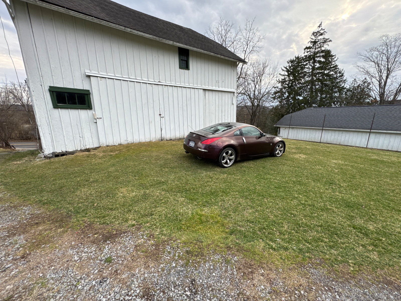
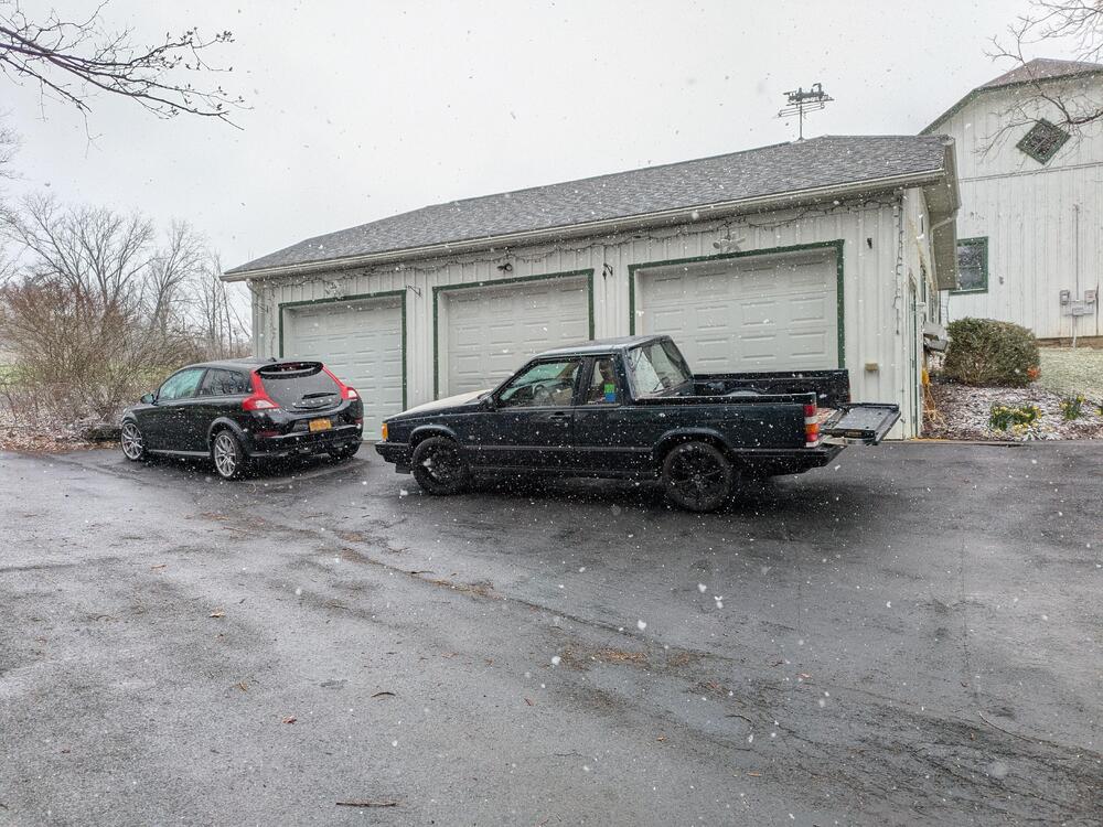
Very cool! Looks like the new shop is a nice upgrade. Looks like you might have more acreage too...1 point
-
I think Yarb's thought might be it needs surfacing.. There are some chatter marks and possibly some blue hot spots too. Yarb, be me to it by seconds...1 point
-
IMO that needs to be machined and cleaned up. From what I can see you have hot spots.1 point
-
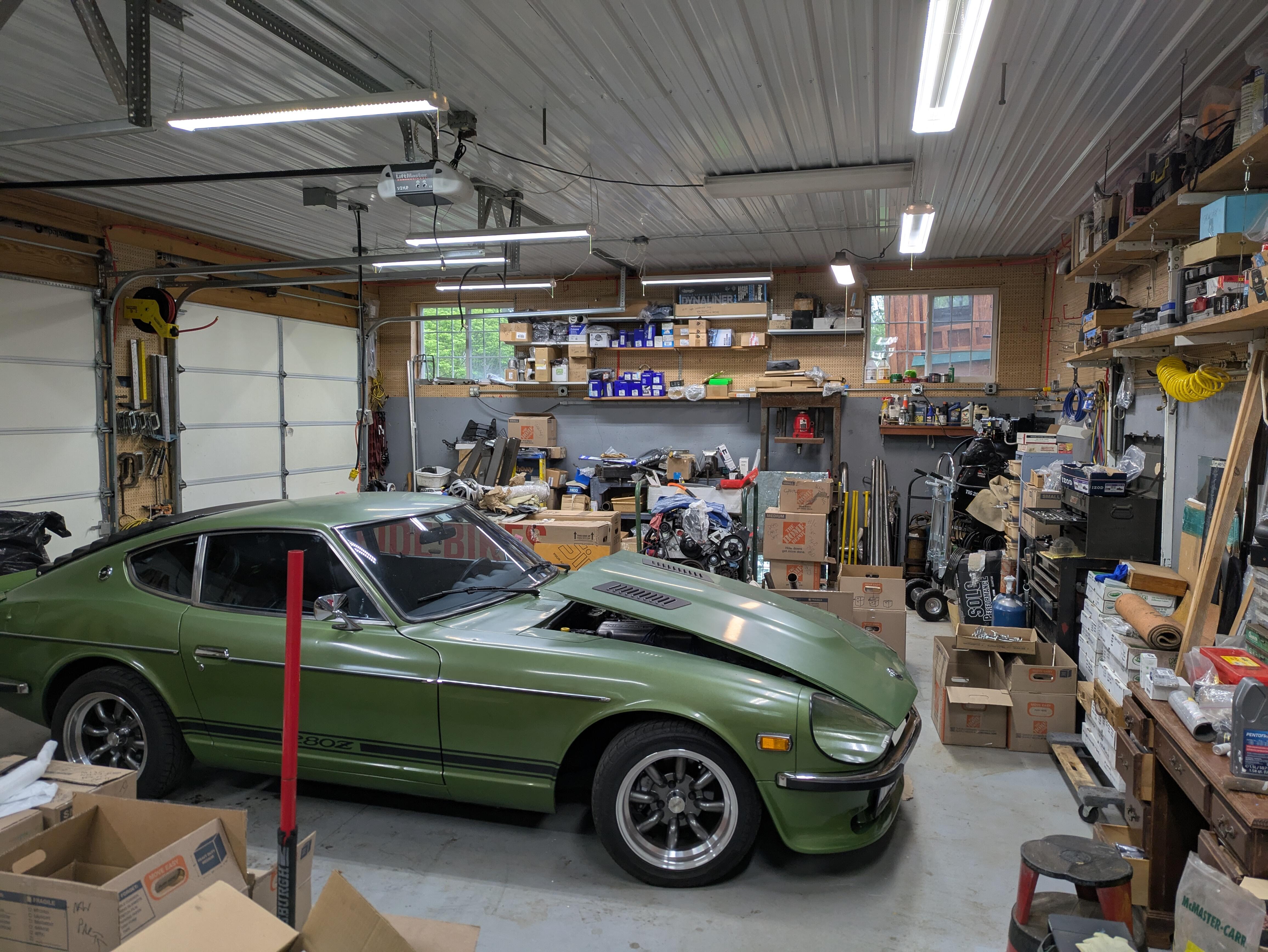
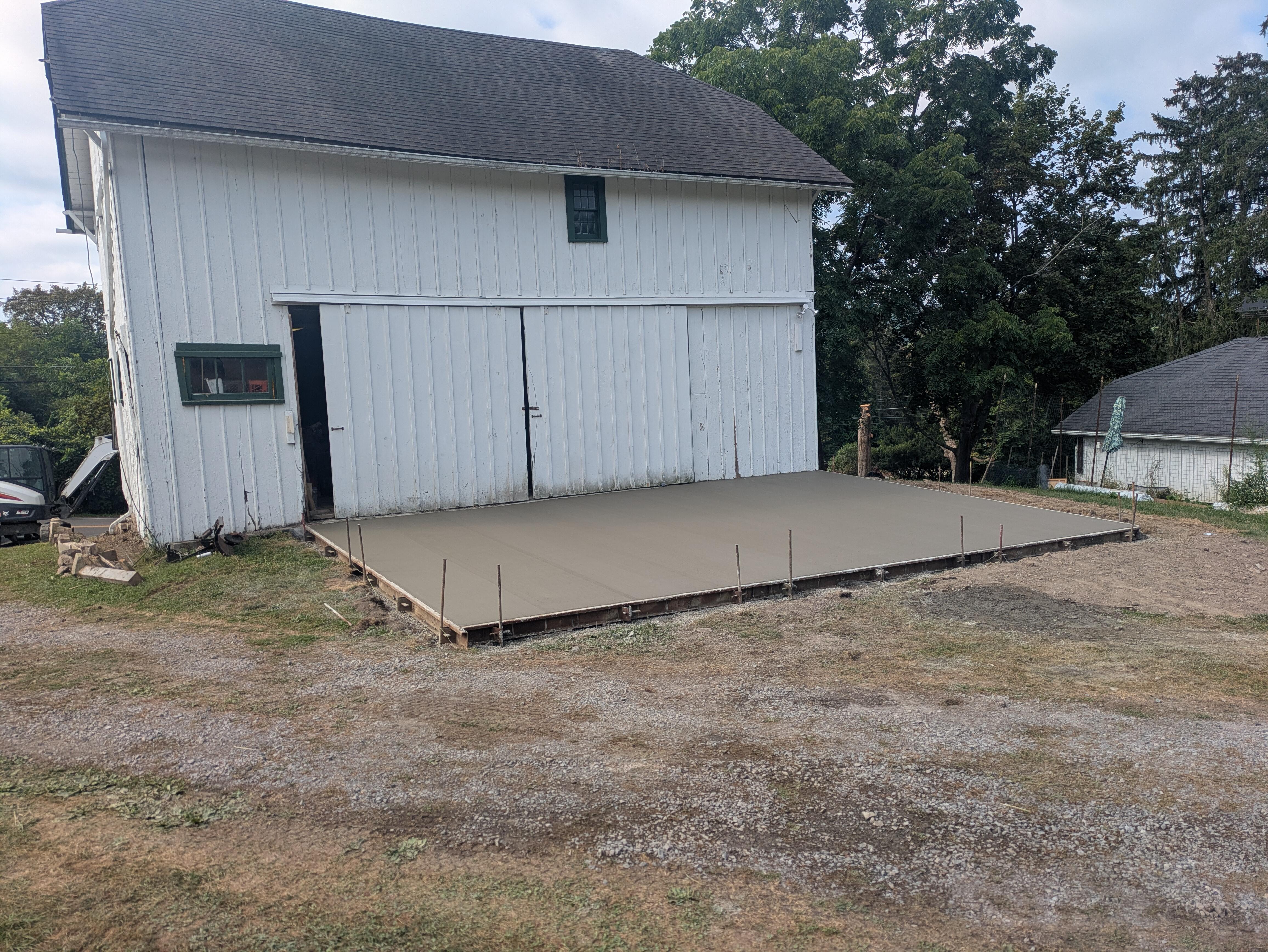
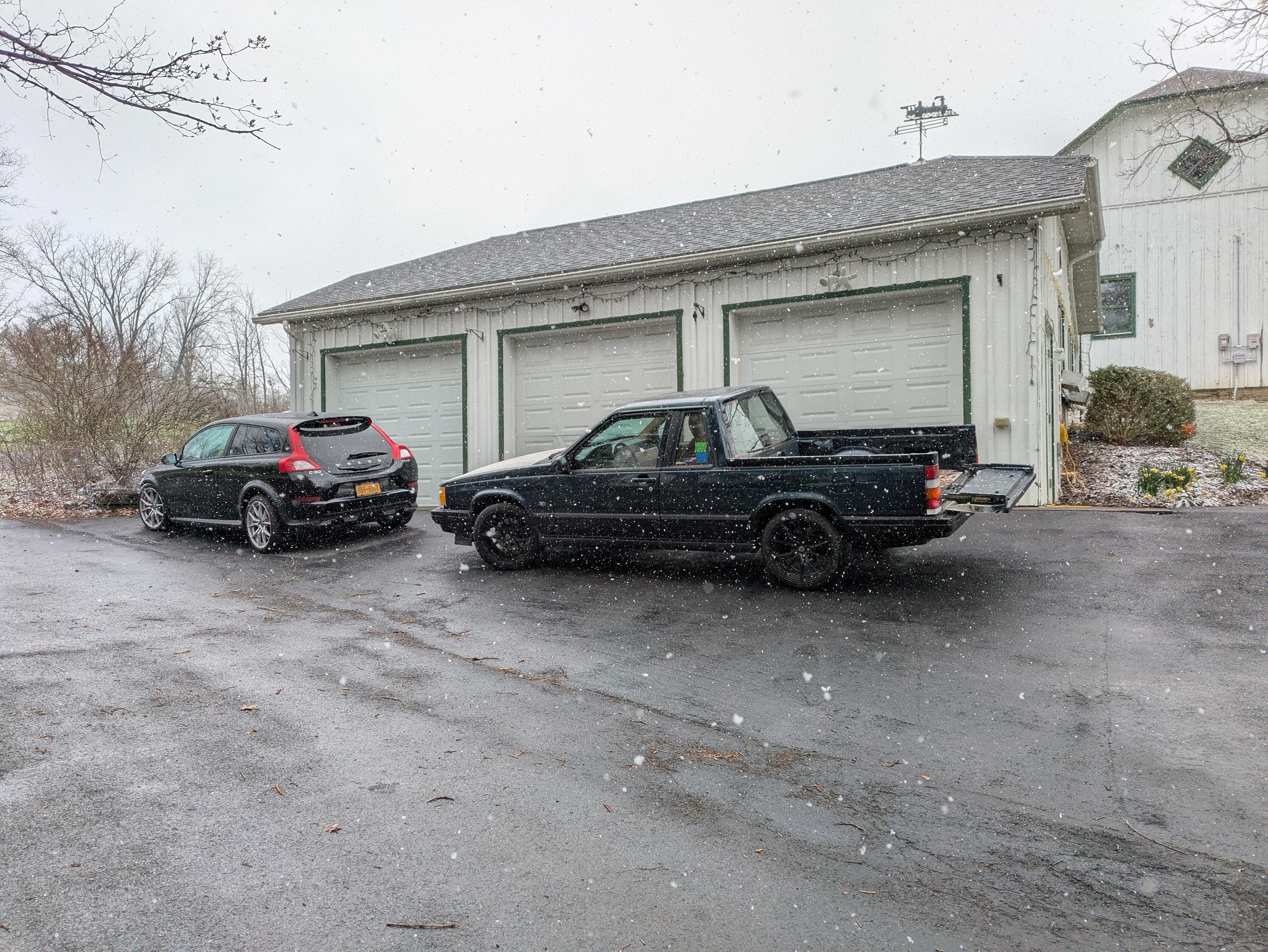
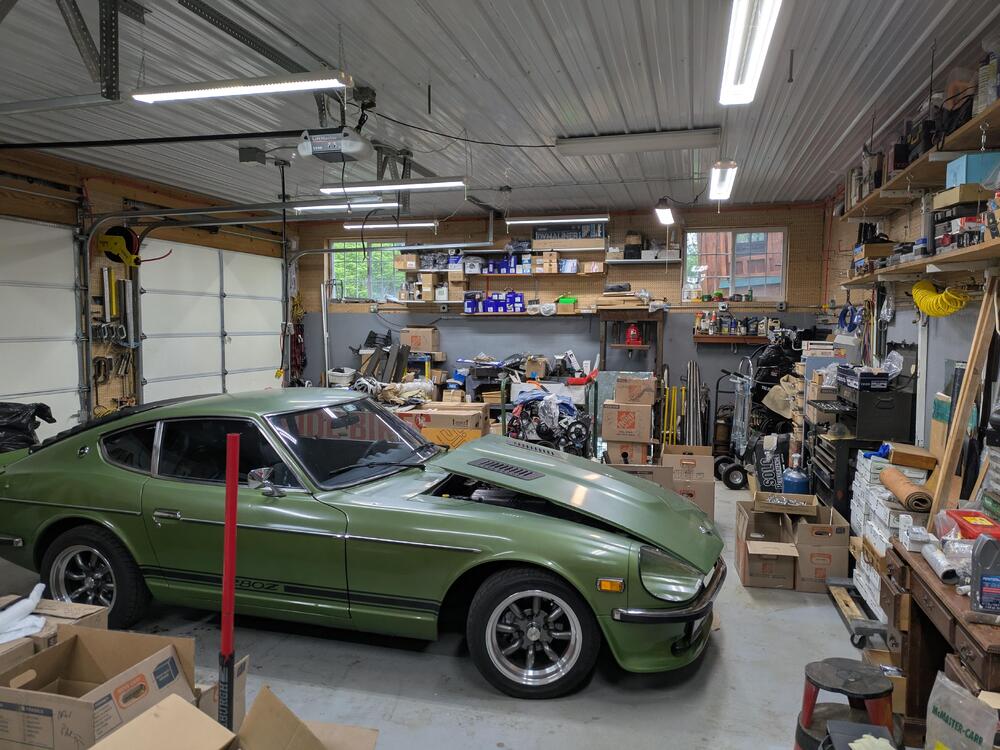
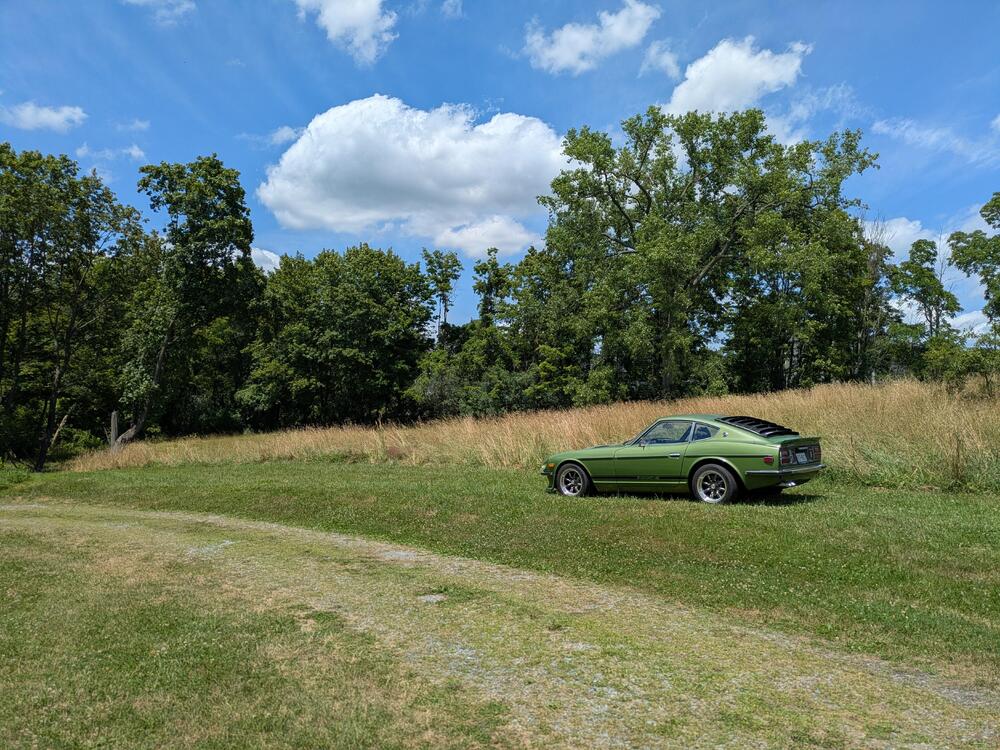
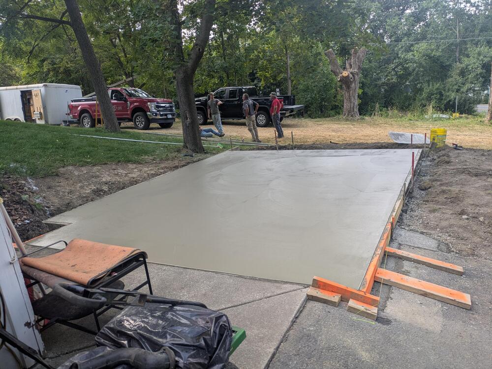
Moved upstate to Ithaca NY back in April. Had the 350Z shipped up ahead of us, then took the 280Z on. a clear day. Still no work on the cars yet, still setting up the grounds, garage & house Garage was used as. workshop, so it has a couple of 240 circuits, air compressor lines & ports, and radiant heat. Little more cluttered now, still working on setting it up Added glass panels to each door for more light Outside garage back in April: Better weather Adding slabs outside the barn & garage for me to work on - there are no flat/level/safe areas on the property outside of the garage


 1 point