Leaderboard
-
Captain Obvious
Free Member3Points10,081Posts -
Namerow
Free Member2Points1,551Posts -
Matthew Abate
Free Member2Points1,204Posts -

siteunseen
Free Member2Points15,115Posts


Popular Content
Showing content with the highest reputation on 06/08/2025 in all areas
-
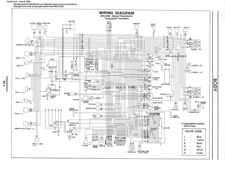
3 pointsHere's the latest wiring diagram. I changed the ground distribution scheme to add the dedicated ground strap directly from the battery terminal to the firewall, and also labeled the ground connections that are through the engine metal. Hope this helps depict how the car is actually wired. I also changed one of the wire colors leading to the fog light switch. Might only matter to people in other parts of the world who have fog lights. <V8.0> _obvious 240Z Wiring Diagram 8.0.pdf
 3 points
 -
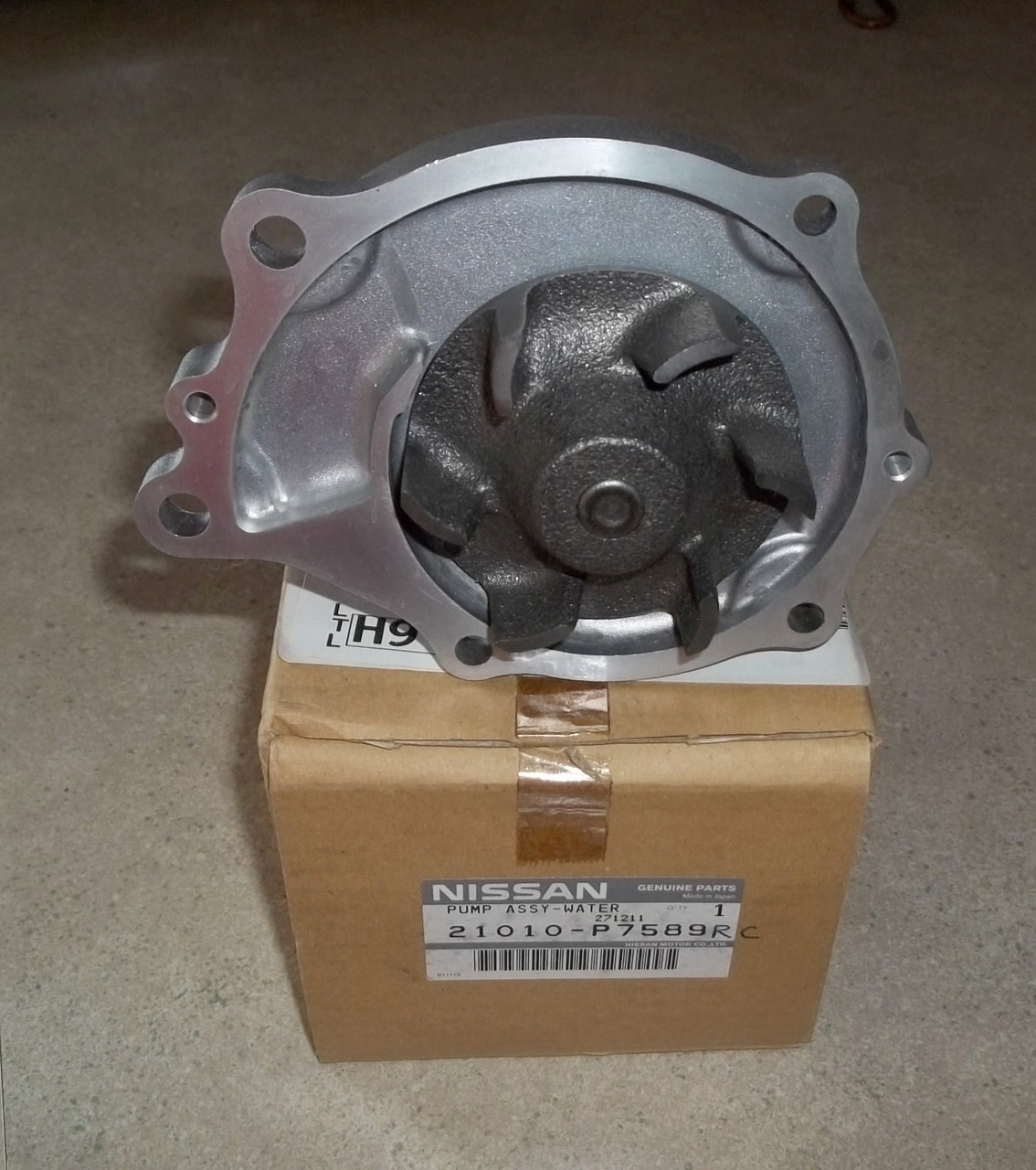
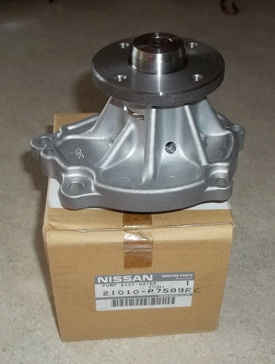
2 pointsI think both those GMBs are aftermarket and agree that an Aisin with the cast iron impeller will be as close to OE that you'll find today unless you can find one using the part number on this box.

 2 points
 -
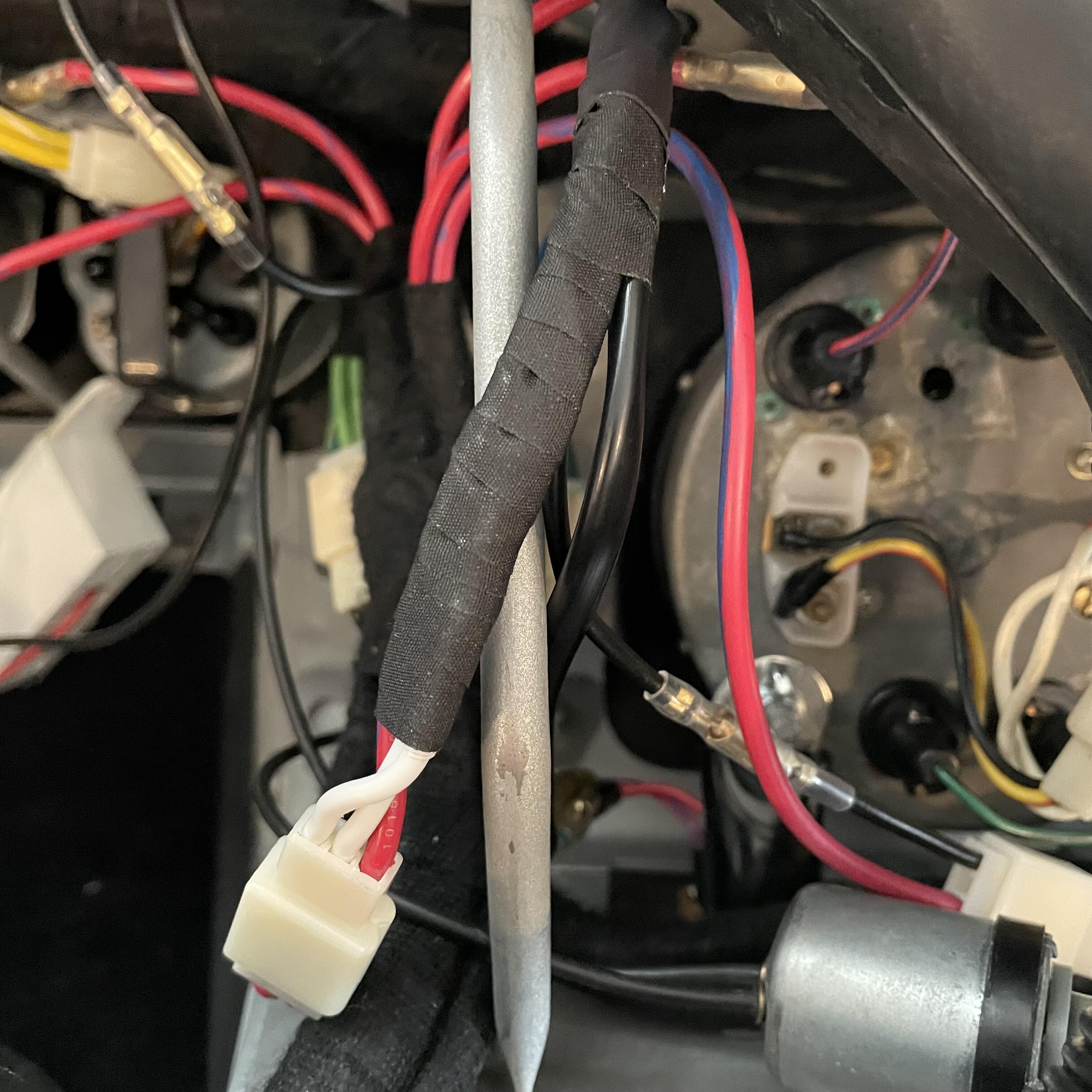
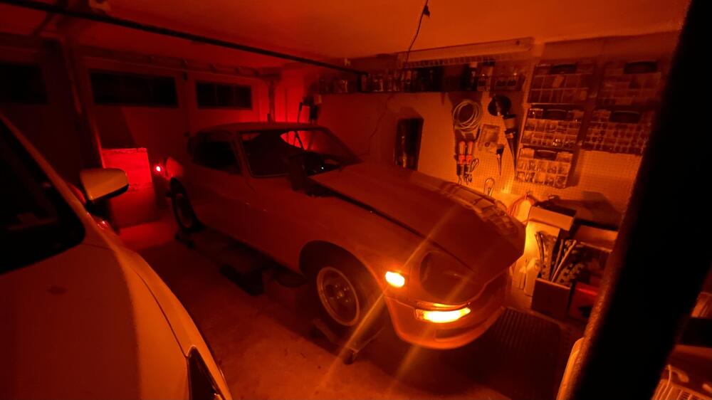
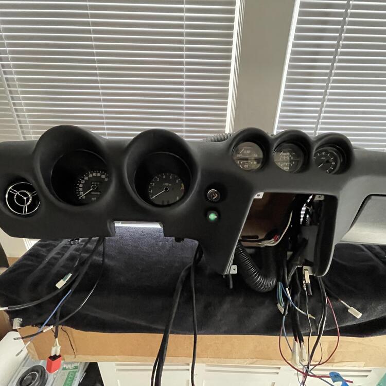
I have lights. No one is going to not see this thing. These LEDs are significantly brighter than the lights on my Subaru. Unfortunately, somewhere between testing it on the bench and installing the dash, the speedo and tach illumination stopped working. I think the main branch of wiring coming out of the dimmer is messed up. I also don’t have any blinkers for some reason. That one is going to be harder to figure out. Worst case scenario is that I made a mistake in the engine harness.
 1 point
 -
1 point
-
Nissan were caught out by changes to motor vehicle 'Construction & Use' regulations with regard to lighting for 1971-up in several European markets. Height from road level was particularly difficult to solve. The regulations even required changes to the illumination of the rear license plate. Of course such regulations applied to NEW cars and many private owners took the opportunity to move these aesthetically unpleasant front turn signals to a position UNDER the front bumper, or - even better - to revert to the configuration that the gods originally intended... A legacy of precedence. You may have heard of Mr James Watt? He found it necessary to use a unit of measurement in order to compare the power of steam engines to that of working horses. Of course he used the IMPERIAL system as METRIC horsepower didn't exist at that point, the Industrial Revolution not being a Continental phenomenon... You may also have heard of Sir Isaac NEWTON? That's him in your Nm measurement. (Posted from The United Kingdom of Great Britain and Northern Ireland, a small place off the coast of mainland Europe which used to rule much of the world for a while... LOL)1 point
-
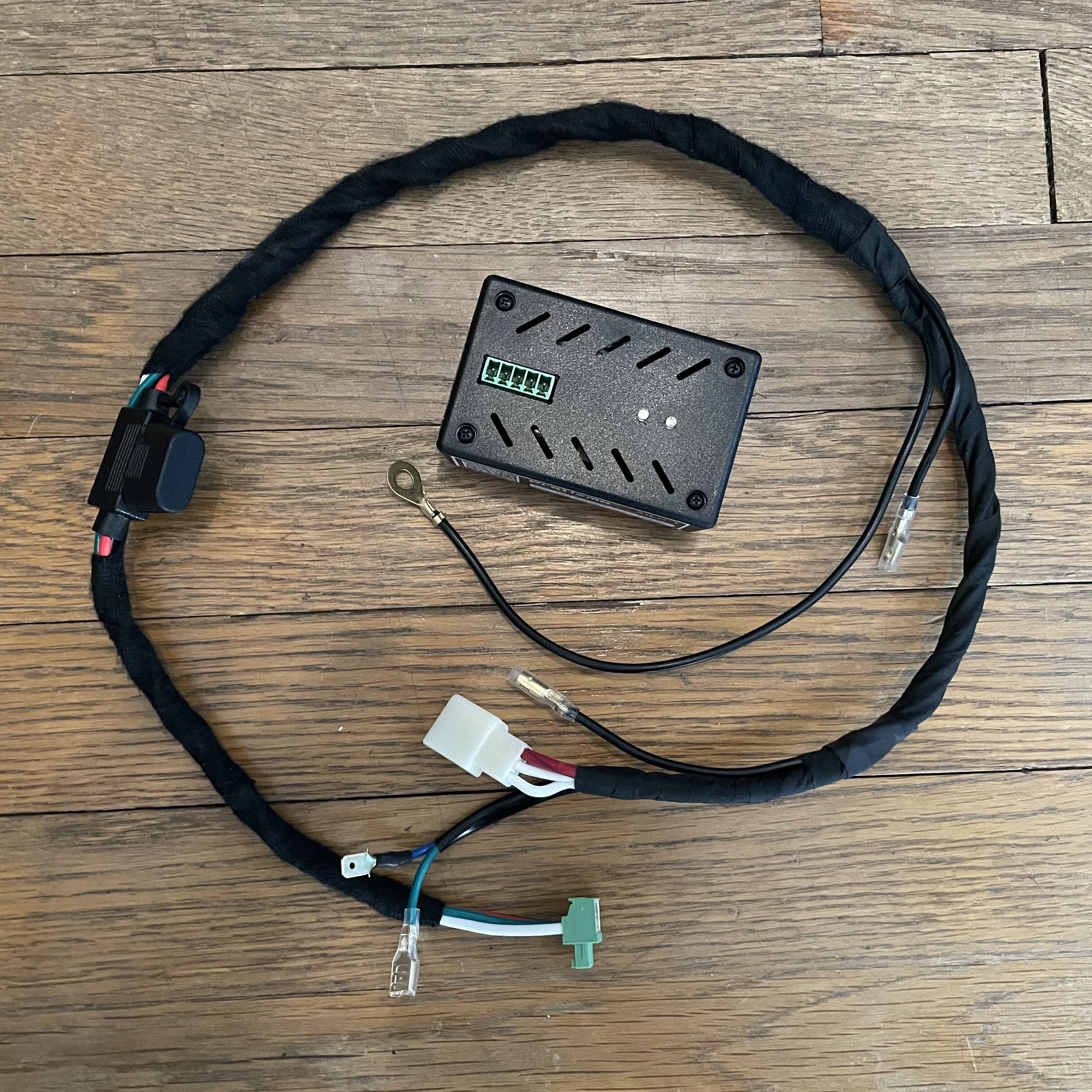
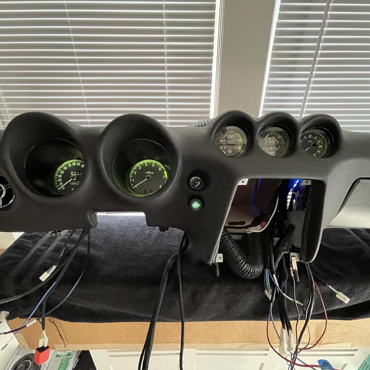
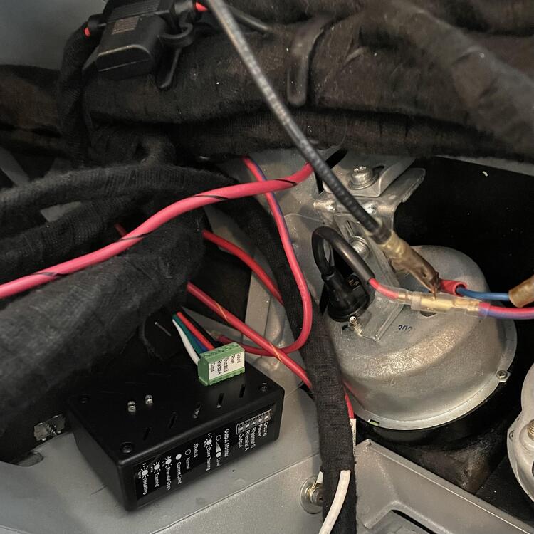
Okay, all of my dashboard wiring is finished. The AILD-1 is being controlled by the OEM rheostat and dimming the lights. I’m a little disappointed that the LEDs don’t seem to come to full brightness. I ran into this issue with another PWM, but the guy who made this one said it can be trained, so I’m hoping he can help me figure out how to fix that. After messing around with a few different methods, I decided to secure it to the inside of the dash with adhesive Velcro. I made a separate harness for it that taps into one of the ground wires for the instruments and the fiber optic light module. The rheostat is completely isolated on the blue and green wires and it’s only function is controlling the PWM. The wires that used to go to the rheostat now go to a connector for that harness. Here are the instruments turned down to zero and the fiber optic light (and all the other lights) still at 100%.


 1 point
 -
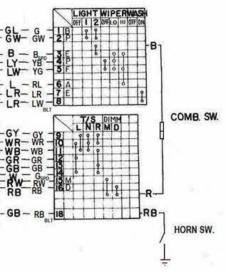
1 pointWhile I'm at it, here's my edit of the mini-schematic for the Combination Switch, corrected to reflect what I found in the actual layout of the wiring and contacts in the Combination Switch installed in my 4/70 car. I started with the mini-schematic that was part of large wiring diagram included with my car's Owners Manual ("20-Mar-1970 - 030300 - OM0E-0S30U2") and then made corrections... Note on the left side of the diagram that I have two columns of wiring colours: The left column indicates the colour of the wiring on the vehicle side of the Combo Switch connector. The right column indicates the colour of the wiring on the Switch side of the connector. 'SPD' = spade-type wiring connector 'BLT' = bullet-style wiring connector
 1 point
 -
1 pointSeveral years ago, I worked with your #2 schematic ("Datsun Factory Parts are fully warranted to give utmost satisfaction") and then added editing comments, using the wiring, connections, and devices in my car (unmolested 4/70 240Z) as my primary guide. See attachment #1. Back in 2015, CZCC member @EuroDat (Chas) did a beautiful job of creating a full-colour wiring schematic based on the specs for MY-1970 USA-Cda cars (see attachment #2). It addresses most of the issues that I identified in my own review. S30 Wiring Schematic - 70 240Z - B&W - 70 Owners Manual - Comments added for errors 7.pdf S30 Wiring Schematic - 70 240Z - Colour - Eurodat.pdf1 point