Leaderboard
-
grannyknot
Free Member5Points5,158Posts -
Hardway
Free Member4Points1,332Posts -
theguppies
Free Member2Points93Posts -
JDMjunkies.ch
Free Member2Points637Posts


Popular Content
Showing content with the highest reputation on 12/23/2017 in all areas
-
3 points
-
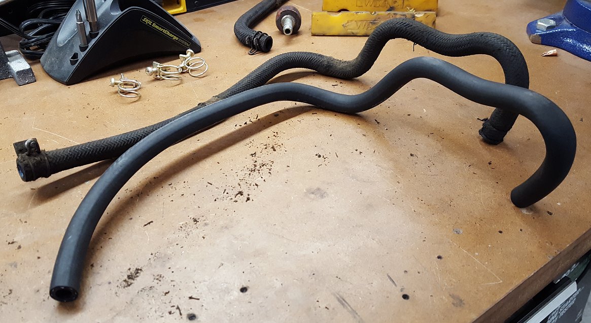
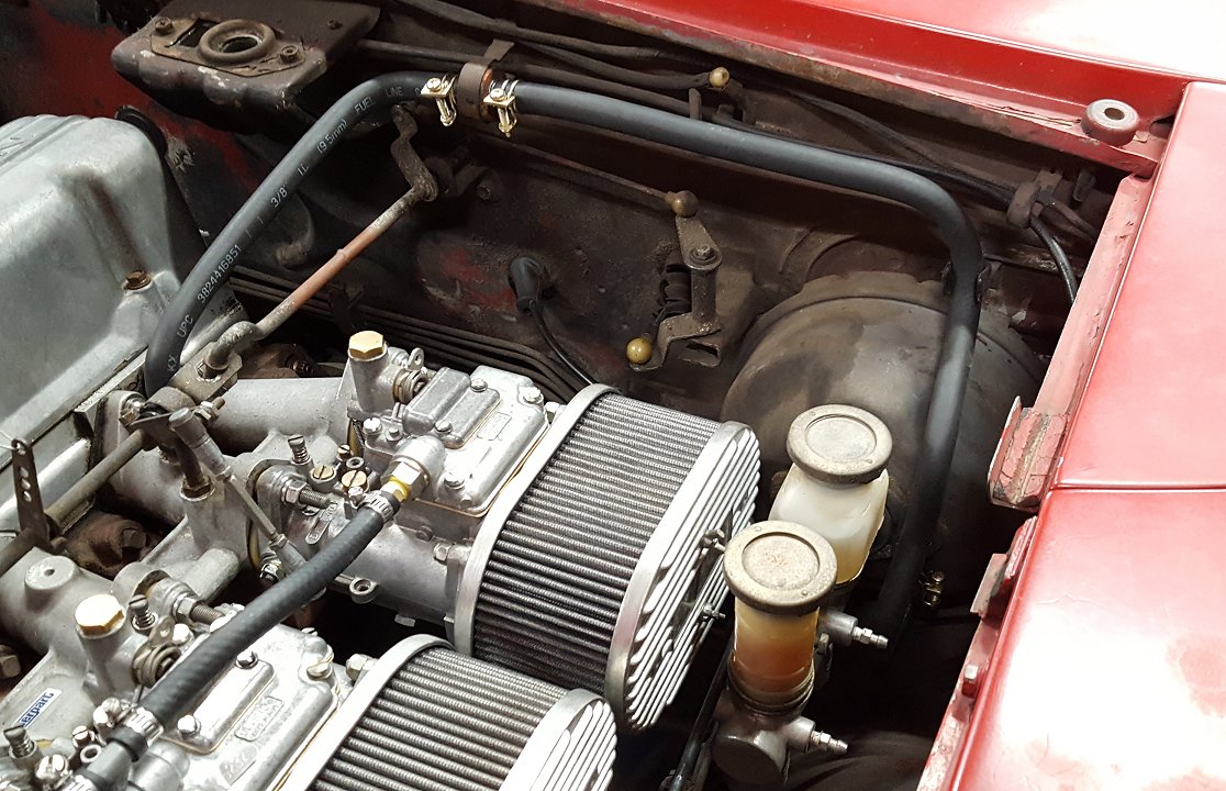
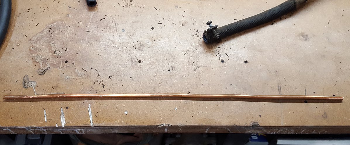
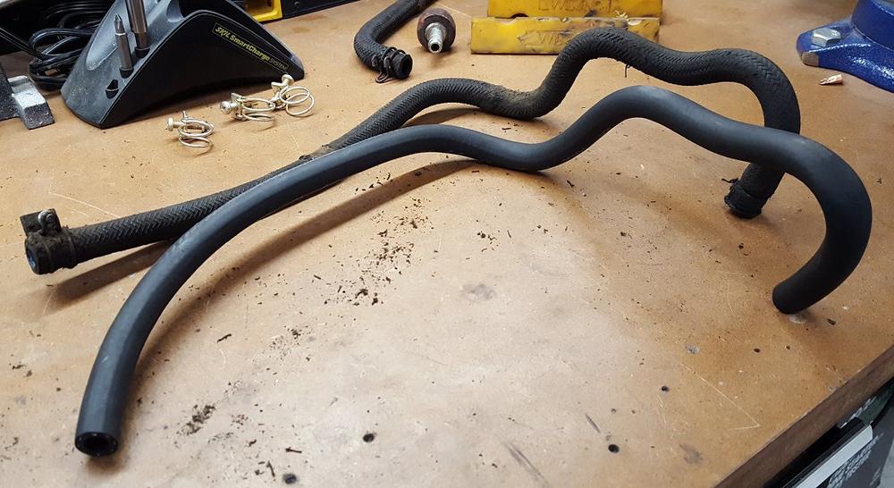
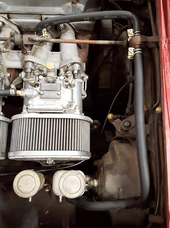
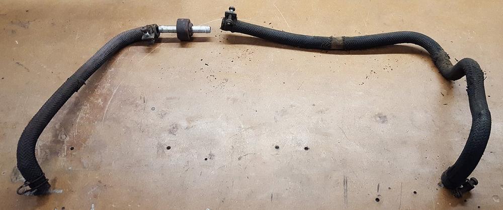
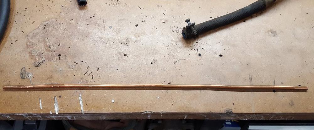
Last night I resolved something that has bothered me ever since I started working in the engine bay... the absolute sorry state of the brake booster vacuum hose. Every time I touched it or breathed hard near it, more of the deteriorating braided fabric would crumble off or leave some part of my skin or clothing dirty. This is no surprise since it is the original hose and I am sure many others are dealing with the same issue. Leaning on the replacement hose experience that AZ-240z made me for my series-1 240z, I knew I could make a new one on my own. I pulled out some solid copper wire I had laying around and straightened a 16" piece of it with my bench vise. I inserted the copper wire in to some 3/8 inch fuel vapor hose and started bending. After about 10 minutes I was pretty happy with the overall shape. I left both ends a little long so I could trim them to fit once they were on the car. I did the same for the smaller hose and used a piece of 4" copper wire at each end to accomplish the bends. With the hoses on the car I did some trimming and adjusting so they fit right. While I was at it I installed some freshly yellow zinc plated original style hose clamps to add a little bling. The end result is not factory or restoration accurate but it is worlds better than what was on the car and fully functional. A few things to note from my personal experience. This was actually the second booster hose I made. When I did the first I used 24 inches 1/4" copper tubing which is much easier to bend and I recommend it over the solid copper wire. However, 24 inches was too much and I had no way to cut it down or push it out once I had formed the hose. When pushing the copper in to the hose, make sure you push it in far enough so it does not interfere with the ports that each end will go on to. That is why you really only need 16 inches of copper. Of course this makes bending the curves on the ends a little challenging but it is do-able. The best part of this project is if you completely mess up, the cost to try again is minimal. Additionally, you are saving yourself a lot of money over buying some pre-molded hose unless you truly need restoration caliber hoses, in that case be prepared to pony up. Next up is my modified choke cable project. Stay tuned and Merry Christmas everyone!

 3 points
 -
2 points@240260280 My dash is new to the market and I'm working on the website. Our shop address is 544 Cleveland Ave. Albany, CA @ray_madera please send me an email at vintagedashes@gmail.com2 points
-
2 pointsI finished most of the electrical connections except for the center console. Also put in new battery cables. Turned the key and the motor turned over nicely Woo-Hoo. It's nice when things work like they are supposed to. Now I just need some to put in the exhaust system and throw some gas in the tank and she should start right up. I should have a little time with the holiday break so should have her running by Tuesday at the latest.

 2 points
 -
2 points
-
2 points@theguppies, beautiful work, this looks like it could be a better alternative to sending your dash out to be restored. Great price too, what are your recommendations for adhering your dash to the original dash frame?2 points
-
1 pointI was over on the 240z 260z 280z facebook group and these dashboards popped up. https://www.facebook.com/groups/386021341481608/permalink/1533611720055892/?sale_post_id=1533611720055892&comment_id=1534205696663161&reply_comment_id=1534500946633636¬if_id=1513832246361651¬if_t=group_comment1 point
-
1 point
-
Christmas comes one day early this year After a four-week long wait, a little Box from Japan finally arrived here with some Parts for my MK63 brakes: 1) Project u MK63 Solid disk type NS street brake pads: 2) NOS Nissan Sumitomo MK63 Brake pistons I think i have everything ready now for assembling the Brakes over the holidays1 point
-
Thank you Phil! Couldn't have done it without the work you did on the books and articles.1 point
-
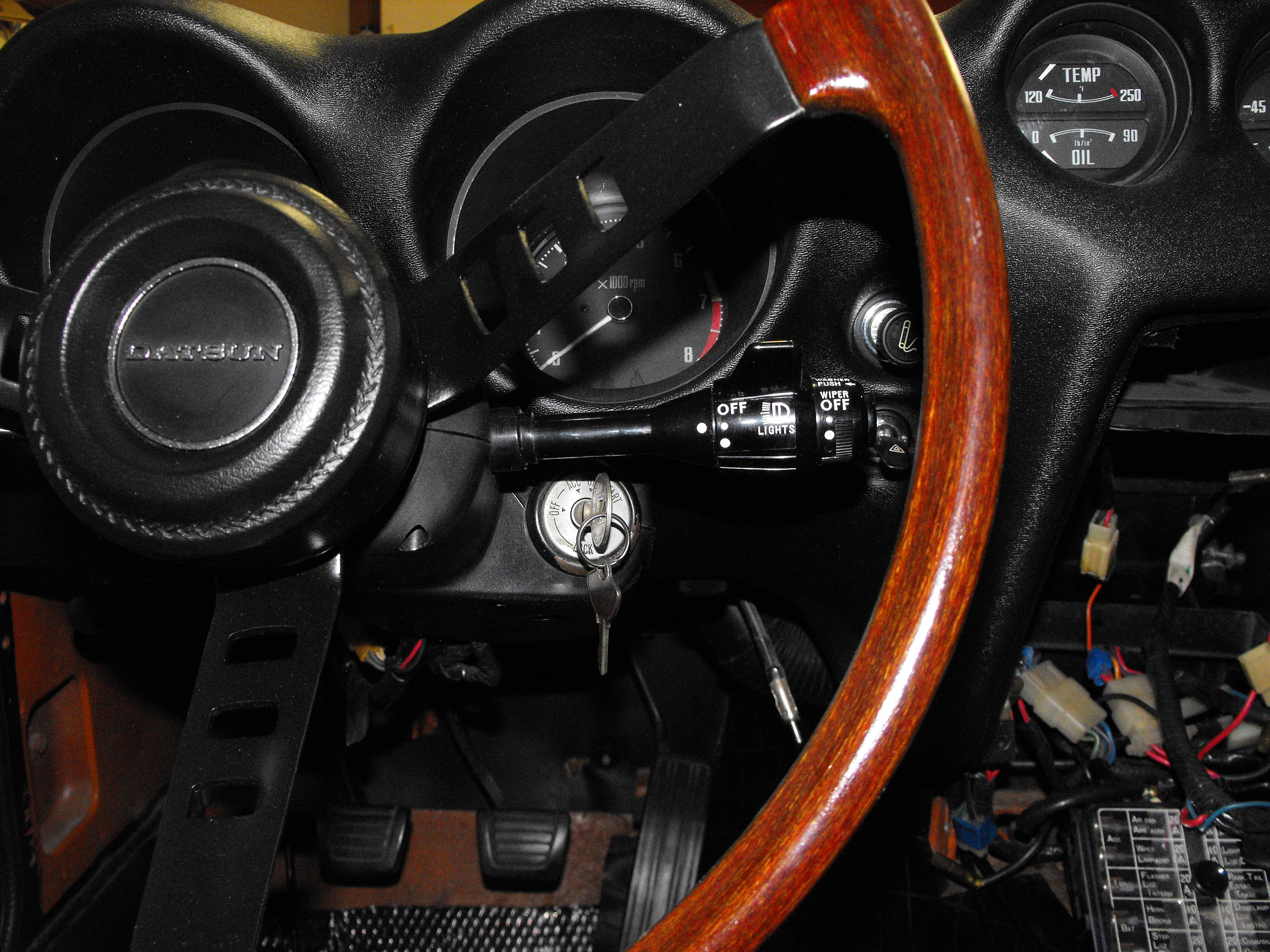
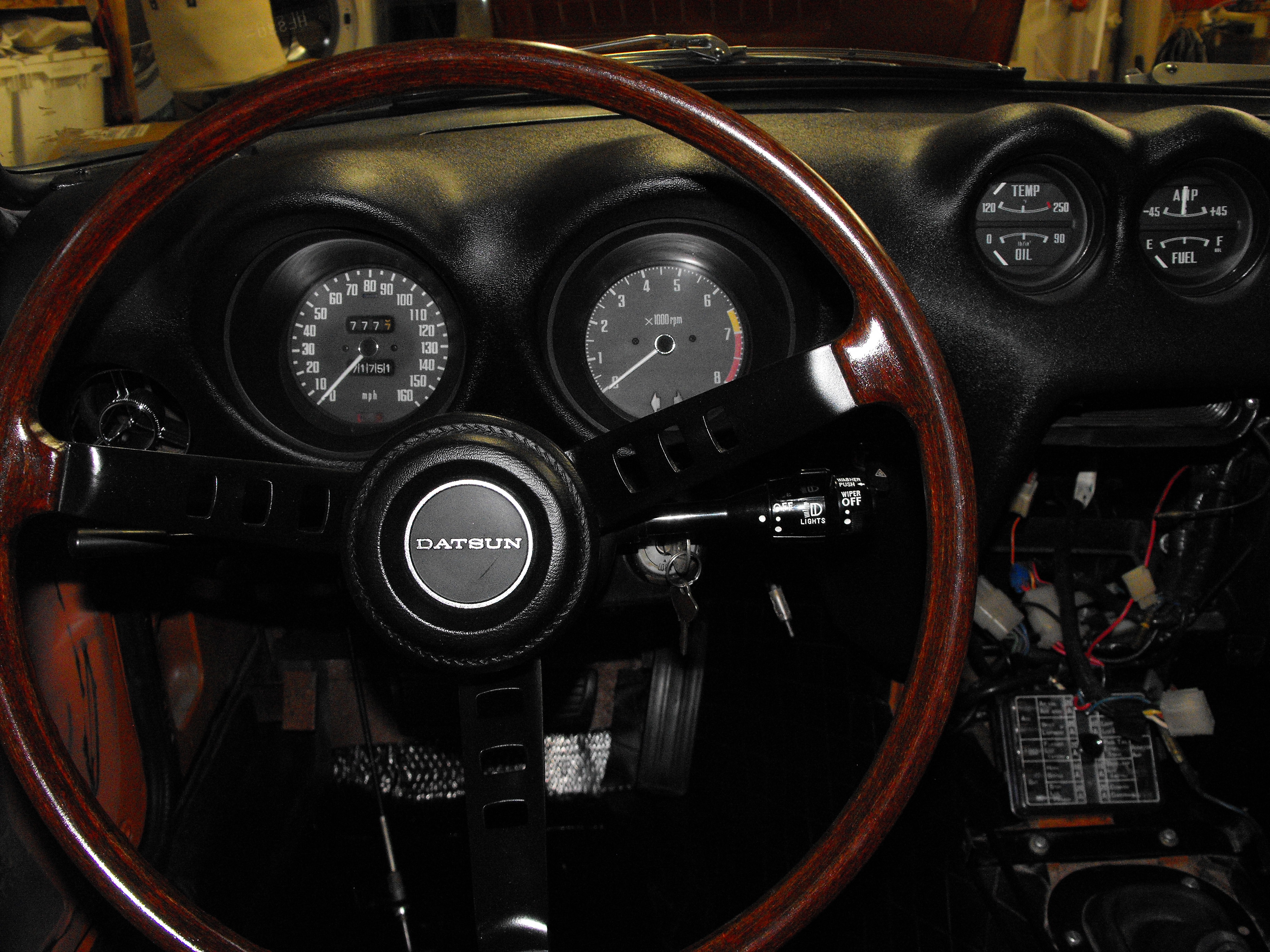
It's likely that the dimmer switch body or terminal plate is broken. No, nobody carries those parts. But, I do offer a complete rebuild of the turn signal switch and the headlight/wiper combo switch. I charge $70 per switch or $135 for the pair to be rebuilt and or refurbished. On a side note, You don't need to remove the steering wheel to remove the 2 switches. The black steering column cover is easily removed with about 5 screws on the bottom half of the shell. Then you'll see 2 screws holding the 2 switches together on the steering column. Unscrew them and carefully unplug all their connections. Message me here or through the website for shipping and payment details. Congrats on the new purchase and good luck, Dave1 point
-
Today i was finally able to complete a little project on which i've been working over the past few weeks. I completely reworked the Inspection Lamp. Remember a few weeks ago when i posted this pic? This is how it all started. Rusty, Painted over a few times, and in bad shape. didn't even work: Of course started to disassembly everything first Then had the housing tubmlered to remove old paint, dirt and rust (picture has other parts included as well, which don't belong to the inspection lamp): And got it zinc-replated and yellow passivated to get back the origina look. Then started to source the missing parts. Even if i'm in the business i failed to find an original green twin-wire with the original thickness. but since the original wire was still in good shape i decided to just clean and keep it. The bulb was a bit of a headscratcher too. but after i figured out the Keyword was "BA9s" (9mm bajonett-socket with single base connector) it was easy to find a fitting bulb, 12V, 8W as the manual states. Nowadays you even could replace it with a lot of less-power consuming LED bulbs, but i decided to keep it oldschool in this case The switch was the most tricky part. the original was toasted (see left). It could be saved and restored but then you still have a completely brittly 40 year old piece of plastic in an outdated electronic design, so i decided to replace it with a newer style switch. The first generation of inspection lamps had a metal switch too, so it's not a completey wrong look. The switch needs a 12mm thread, but must be small enough to fit inside the housing (most 12mm threaded switches are too big) and it should have the little notch in the thread to secure it properly in correct position. After trying various options i figoured out this one would fit perfectly (Available at farnell) http://www.atakel.com/urun/apem-5000-series-miniature-toggle-switches/EN/ While the original one is an ON-OFF switch, this one is an ON-ON switch, but if you remove one of the outer pins you have an ON-OFF function again: First the little nipple has to minimized by 0.5mm or so to fit the slightly smaller notch in the new switch: Then prepared all the cables. Cleaned them first with a rough side of a dish cleaning sponge, cut off the ends, removed insulation ca 1mm at each end with a special tool and then pre-soldered the ends to make it easier to solder it later. It probably helps if you have a full high-end soldering workstation like i have at my office and 20+ years of daily soldering routine skills All parts ready? Here we go. The fun part begins - assembly (got a new replica lens and rubber insulator from ebay, plus additionally a piece of black heat-shrinking tube and some red electronic wrapping tape). First i installed a new rubber insulator grommet on the bottom of the back housing. the original one was falling apart by just looking at it. New ones can be found easy in any electronis speciality shop. The removed the old wire-end from the connecting plate and cleaned it. resoldered the new wire-end to it and cleaned it with flux remover (removes flux from the soldering, which may decrease the electric connectivity! see bottle in the back) Soldered the other wire back to the hook and attached some black heat-shrinking tube like it was in the factory setup: Next was soldering the wires to the switch and protect the solderings with some black heat-shrinking tube: Also added the red electrical tape as it was in my factory setup (it goes inside where the clamp is to protect wires): Soldered the wire back to the little Clamp And installed the clamp back to the bottom and secured the cables inside with it. Done Apply 12V DC to it (ground to the housing, plus to the red wire, switch on - YAY! assembled it to gether and still everything works as it should: So here's the result. Quite the difference when compared to the first pictures, which was the same item! Spent quite a few hours sourcing parts and getting everything cleaned and so on, but honestly it was totally worth the work1 point
-
1 pointSeriously though, strut changes are pretty easy, with a few simple tricks, like unbolting the inner bolts of the control arms, for the 280Z. The 280Z struts are longer than 240Z so the descriptions of just dropping the back struts out form under the fender wells don't work. Unless you unbolt the inner attachment points.1 point