.JPG.cfcada9cf1c1b502df3f5f2f2ca3ff36.JPG)

SteveJ
Community Member
-
Joined
-
Last visited
Everything posted by SteveJ
-
As @zclocks said, you need a meter that can read capacitance. I prefer to use my Fluke for that. However, if you don't want to spend $200 for a Fluke, you can always try a cheaper alternative like this: https://www.amazon.com/AstroAI-Multimeter-Ohmmeter-Voltmeter-Non-Contact/dp/B0842HTN8C It's just as easy as putting the meter on the capacitance setting and touching the leads to the two wires on the capacitor. By the way, having a capacitance meter can be handy for testing your home AC. I've used it to find a dead run capacitor for both of my units and a friend's unit. Having a good meter saved me a few hundred in service calls.
-
I guess she didn't.
-
I actually consider it a fortunate mistake because it gave me a better understanding of how the horns work.
-
So last night I wanted to see if I could improve the sound from the horns @Tirnipgreen asked me to work on. One was nice and strong. I wasn't going to mess with success. The other wasn't working, though it worked before. I could tell it was pulling in the diaphragm, but the contacts weren't opening. This was verified by taking current measurements on that horn and one that worked. The non-working horn was pulling a lot more current. I tweaked on the parts repeatedly, but I couldn't figure out why that one horn would not work. Finally out of frustration, I took the other horn apart to compare the diaphragms. The problem then stuck out like a sore thumb. Whoever reassembled the diaphragm on the horns didn't put the parts back together in the right order on the non-working horn. The fiber washer was on the wrong side of the bar between the diaphragm and the bar. This is how is should be. So when the diaphragm tried to open the contacts, it was still providing a path to ground for the coil. With the coil still energized, the diaphragm wasn't moving. Once the diaphragm was assembled properly, the horn worked just fine. With the new knowledge, I decided to re-shoot the video to go over the details of the horn. I just have to edit the new video.
-
https://www.summitracing.com/parts/ear-510erl/make/nissan/model/280z
-
I got @Tirnipgreen's horns working and got an old pair of horns from my 260Z working, too. I posted information here: I did shoot some video that I need to see about editing into a YouTube video.
-
I posted more about the horns in this thread: I took some video of the work that I need to edit and post on YouTube.
-
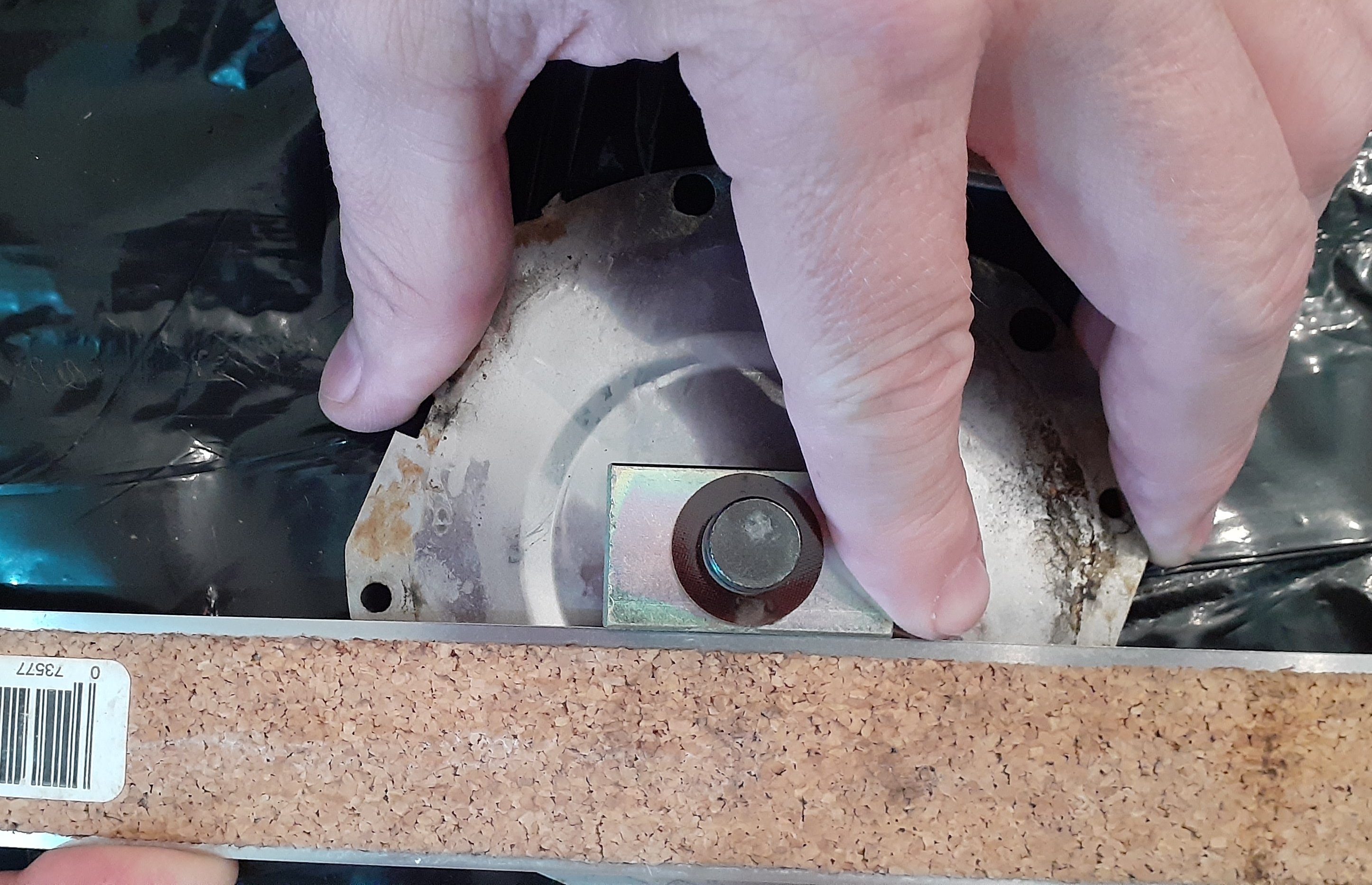
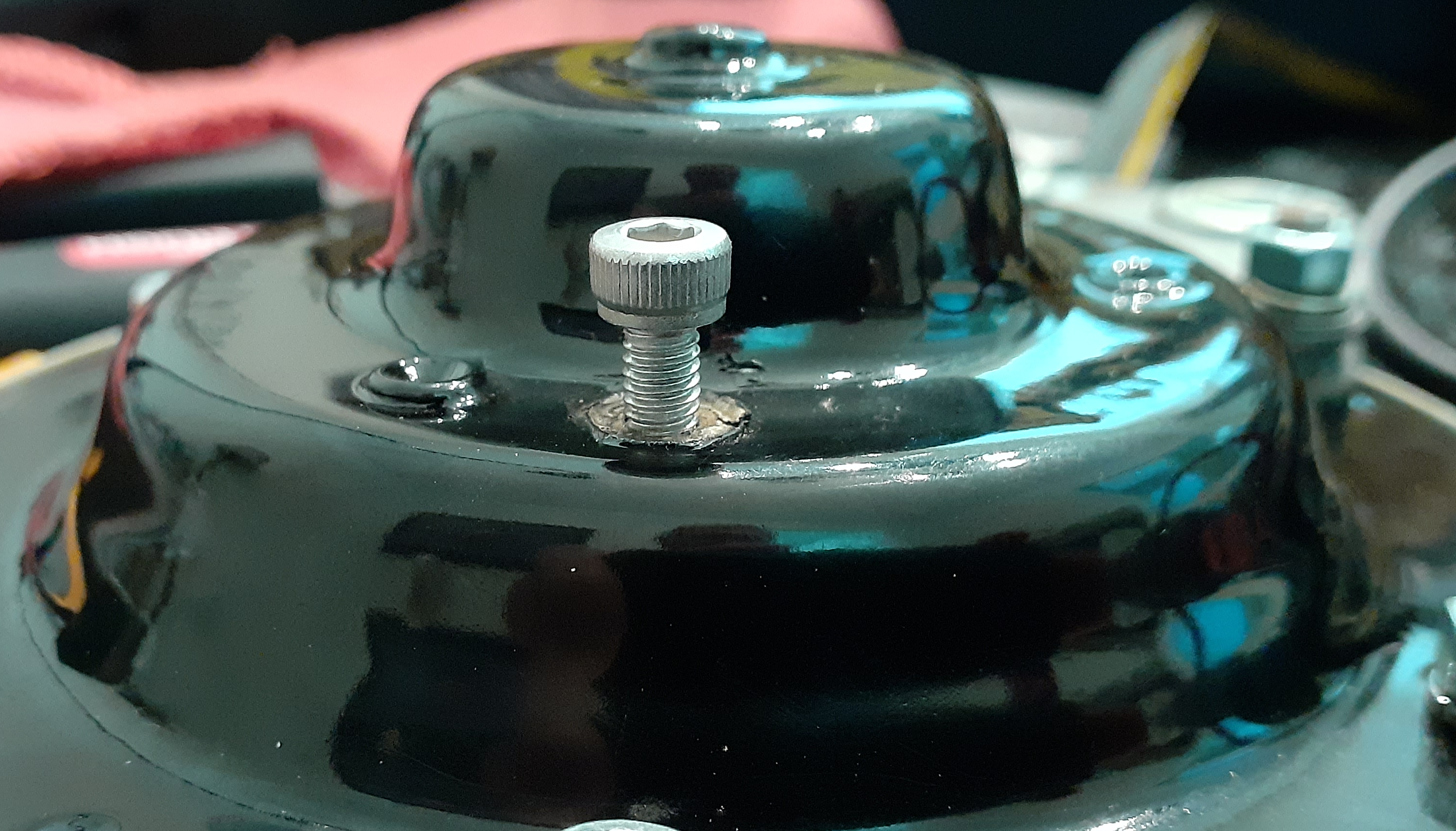
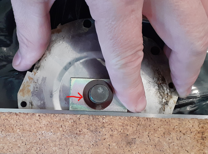
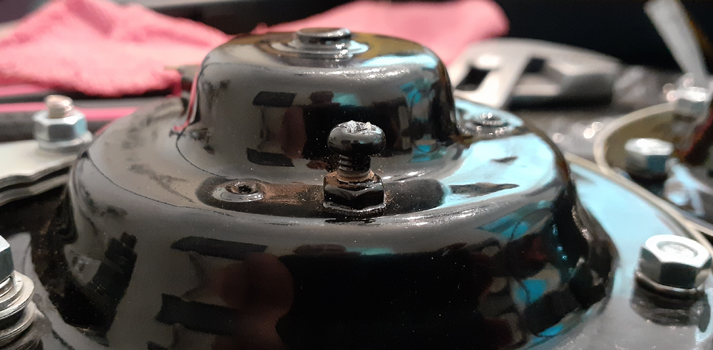
I cracked the code on the horns. I was working on getting @Tirnipgreen's re-plated horns working. I tinkered with them some a while back, but I needed some time to focus on them to get the bugs out. Fortunately I had one of my old 260Z horns that was unmolested to use as a template. Before I go into detail, let's talk about the theory of operation. When you press the horn button, the relay sends voltage to the horn. The coil in the horn is energized, pulling the diaphragm in. The bar on the back side of the diaphragm hits a tab on a set of contacts on the negative side of the coil, de-energizing the coil. The diaphragm snaps back into place, allowing the contacts to close. Repeat steps 2 through 4 as long at the horn button is depressed. The vibration of the diaphragm is what makes the sound. So what appear to be the potential failure points? The tab for the positive wire on the outside of the horn loses electrical contact with the coil inside the horn. The contacts get carboned up. The bar on the diaphragm is not aligned properly. The tone screw is not adjusted properly. I don't have a documented fix for #1. You see it by measuring resistance between the outside tab and the inside of the horn where the coil wire is mounted. Ideally, you should have continuity. For #2, test by measuring resistance from the positive side of the coil to the body of the horn. It should be less than 2 ohms. To lower resistance, I cut a 3/4 inch wide strip of 1000 grit sandpaper and folded it in half. I worked it between the contacts and pulled it through a couple of times, using the tab on the contacts to moderate the pressure. I measured resistance from the positive to body of the horn until it dropped to less than 2 ohms. For #3, I took a straight edge and held it against the side of the bar. There are two alignment holes on the diaphragm, and I noted the distance between the straight edge and the hole. It's between 1 and 2 mm. If the bar on the horn you're working on doesn't line up that close, loosen the M6 nut and rotate the bar. Hold it in place carefully while locking now the nut. After adjusting the internals, put the horn back together. Measure resistance from the positive tab to the mounting bracket of the horn. If it's more than 20 Ohms, the tone screw is turned in too much. The tone screw is an M4 screw on the back of the horn. The screw in the photo below was powder coated onto the horn, and I had to break it loose. I got the resistance from being over 1 MOhm to around 2 ohms. After that I used a car battery to test the horn and get a better tone. I had to work the screw in and out a few times until I was happy with the results. 20230910_153848.mp4 The other horn was a little more challenging. When I tried to break the screw loose, the screwdriver chewed up the head. I had to replace it with the only screws I had available, allen head screws. After playing around with the height of the screw, I finally got a decent volume out of it. 20230910_160521.mp4


-
I used the roadster belts in both of my Z cars. Yes, the retractor mounts near the quarter window. Here's what you're looking for: https://www.wescoperformance.com/noname.html
-
I'm actually working on some horns right now, too. I'm shooting video of it, so maybe it will help someone in the future. Anyway, I see 3 main areas for problems. The rivet holding the positive terminal isn't making good electrical contact through the horn body from the tab on the outside to the coil wire. The contacts between the negative side of the coil and the body of the horn are carboned up. I used a strip of 1000 grit sandpaper folded in half, worked it between the contacts, and pulled it through. The bar on the diaphragm that opens the contacts isn't adjusted properly, so it doesn't open the contacts. You call tell this in a test if you feel the diaphragm pull in when you apply voltage to the horn.
-
The extractor kit I linked goes inside what's left if there is a hole in it.
-
Of course, that would explain fuel pump issues.
-
Do you mean like this? https://www.vintageconnections.com/products/6-3mm-connectors?variant=46131501236545
-
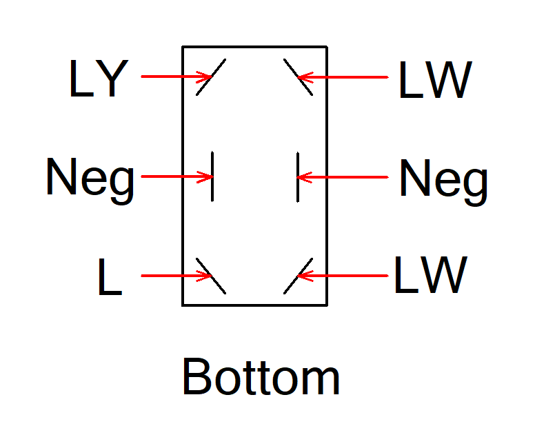
One thing I'd like to add, @Patcon & @grannyknot, Consider getting a DPDT switch like this: https://www.amazon.com/Heavy-Handle-Momentary-Toggle-Switch/dp/B000LFVFA8 You can wire the LW, LY, L, & battery negative wires to the switch. Battery negative goes to the center posts on either side of the switch. LW gets wired to one pole on each side of the switch. L gets wired to one side, and LY gets wired to the other side. You might want to mount the switch to something because the terminals might get warm. Also don't forget to fuse the positive at 20A and use 14AWG minimum.
-
If you're near a Harbor Freight, you could get these: https://www.harborfreight.com/screw-extractor-and-left-hand-drill-bit-combo-set-10-piece-63987.html https://www.harborfreight.com/3-piece-t-handle-tap-wrenches-38560.html Also 25% off coupon that's good today and tomorrow: (https://www.harborfreight.com/promotions) BTW the coupon will work for jack stands. I wanted to get a set of 6 ton stands, so it worked for about $20 off today.
-
Take a photo of what's sticking out and post it here.
-
Sure, but you'll probably need a car battery or heavy duty power supply to make that work. LR - 12VDC+ B - 12VDC- Low - Connect L & LW to 12VDC- High - Connect LY & LW to 12VDC-
-
Well, I searched more. They have 9 & 11 mm, too. https://www.authenticclassics.com/SearchResults.asp?Search=cloth+braided+type+fuel+hose
-
2? 4? What difference does it make?
-
And this place has 9 & 11 mm ID https://www.autohausaz.com/catalog?k=braided+&b=&page=1&sortby=r
-
Here's some, but at a much higher price. https://www.authenticclassics.com/Mercedes-Cloth-Braided-type-Fuel-Hose-8mm-I-D-p/auth-008783.htm
-
Many different sizes are available from Belmetric. https://belmetric.com/hose/gasoline/
-
I actually happened across some of your posts there when I was doing research on EDIS with Megajolt today.
-
I don't recall ever seeing security screws on the ignition switch module, and that includes 2 new Beck Arnley full switches that had Nissan part numbers on them. (I never knew Beck Arnley was a Nissan supplier until I bought them.) On the other hand while it's security via obscurity, it is not a trivial task to get to those screws. It would be a determined thief doing that, and at that point he's going to take your car pretty much any way he can. I have replaced the ignition switch module on a car just as I described. It helps to have a stubby screwdriver or a mini ratcheting bit set like pictured below.
-
Yes, the vertical is for the fuel pump, and the top of the T is for the gauge.