HusseinHolland
Community Member
-
Joined
-
Last visited
Everything posted by HusseinHolland
-
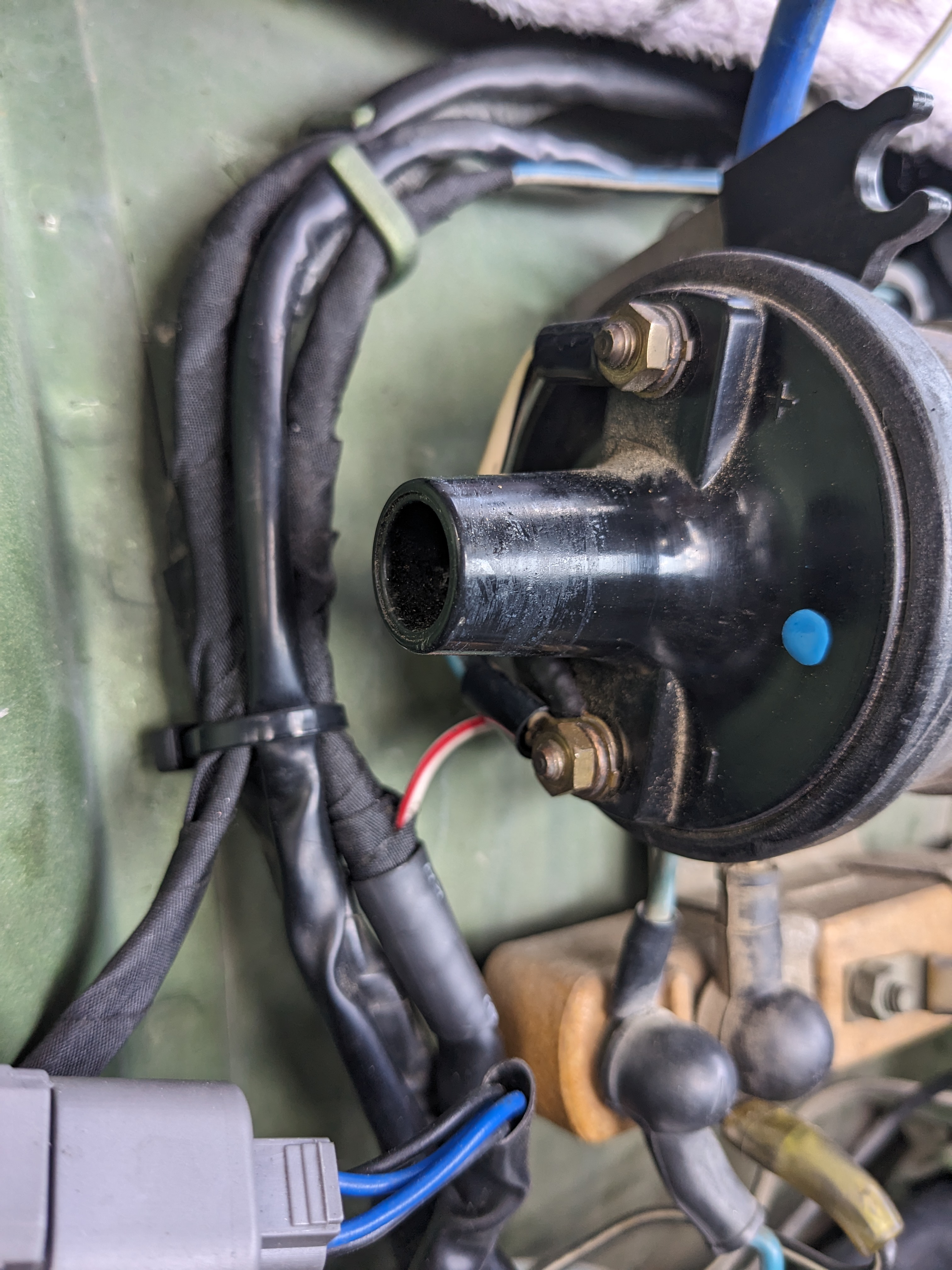
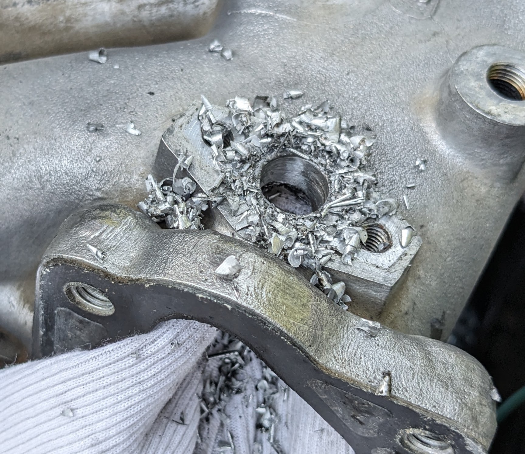
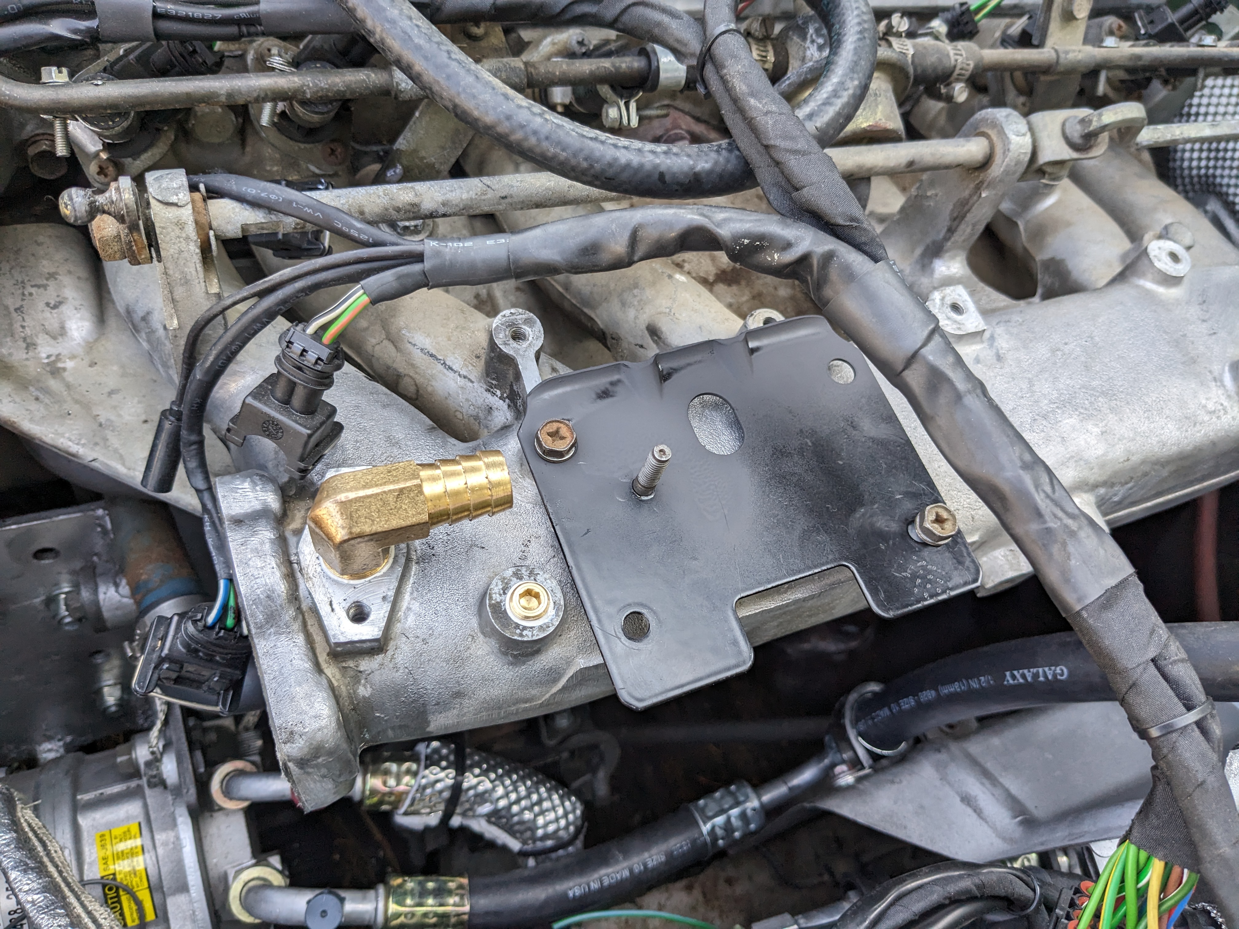
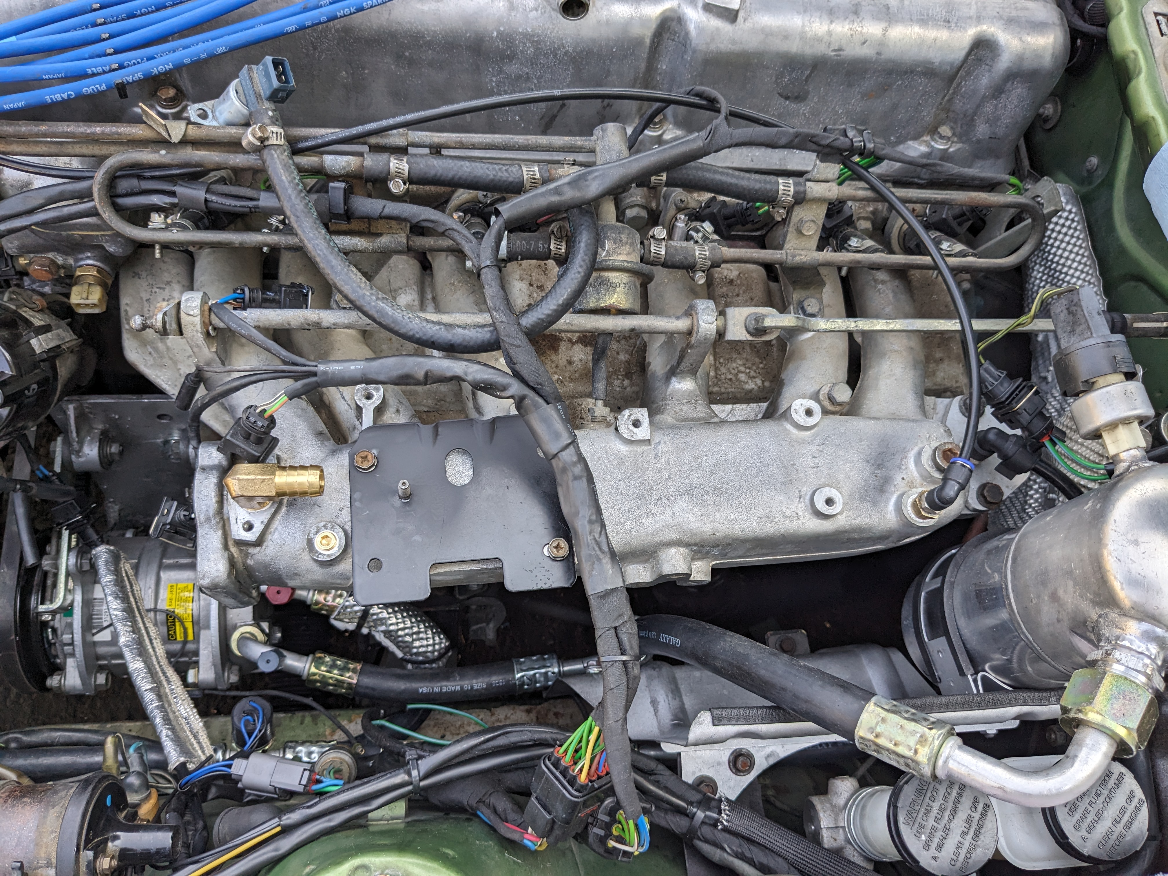
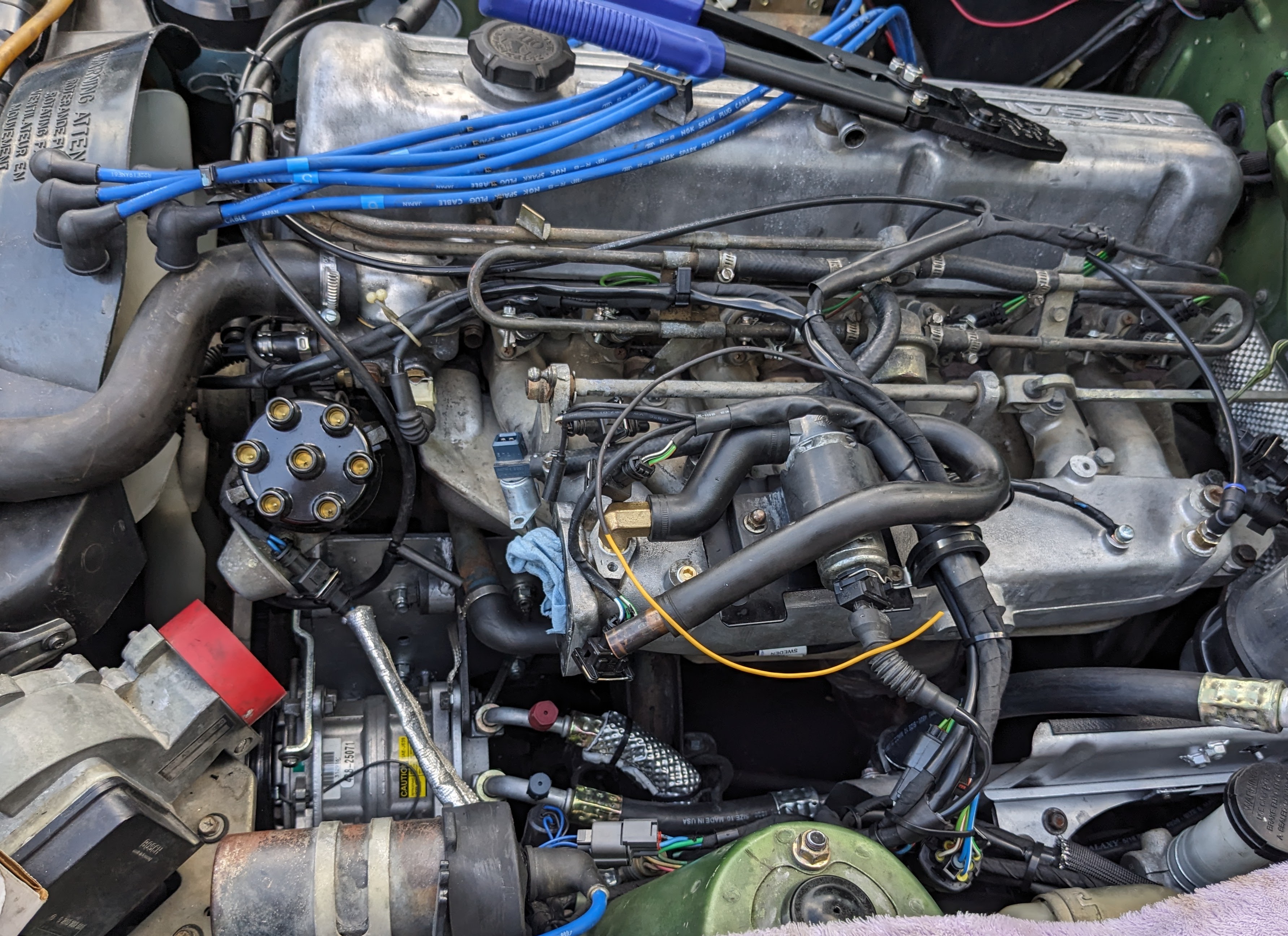
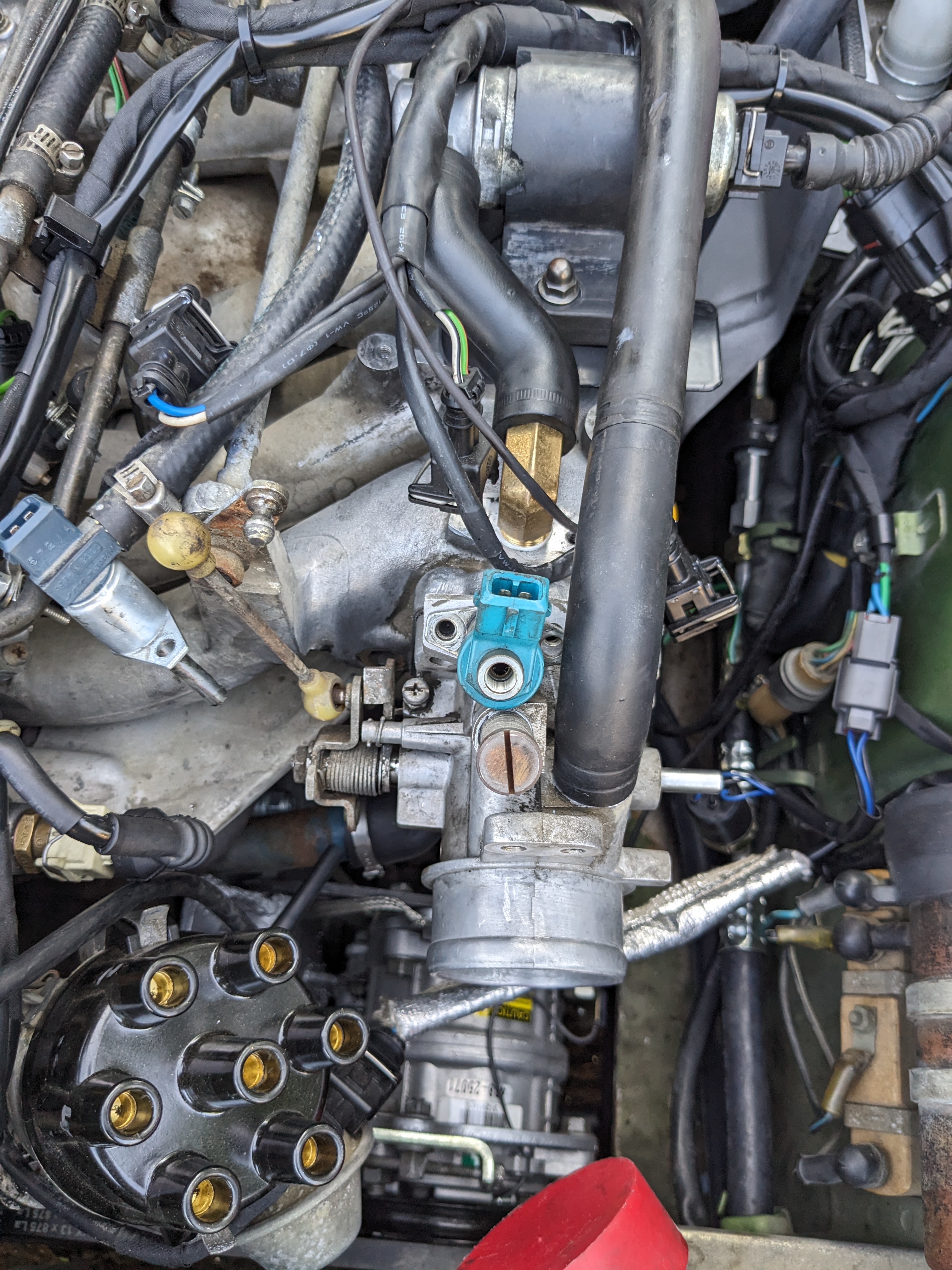
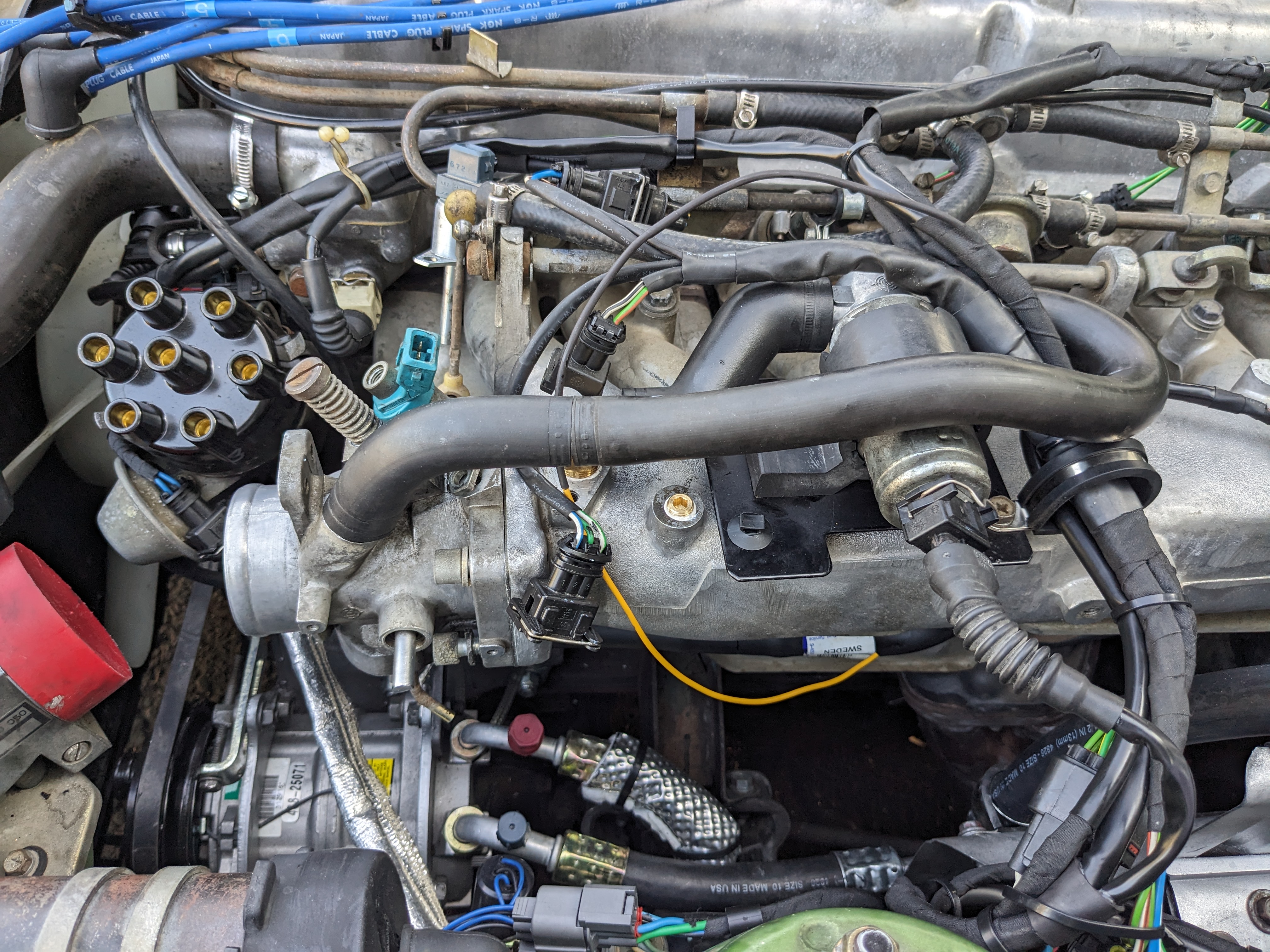
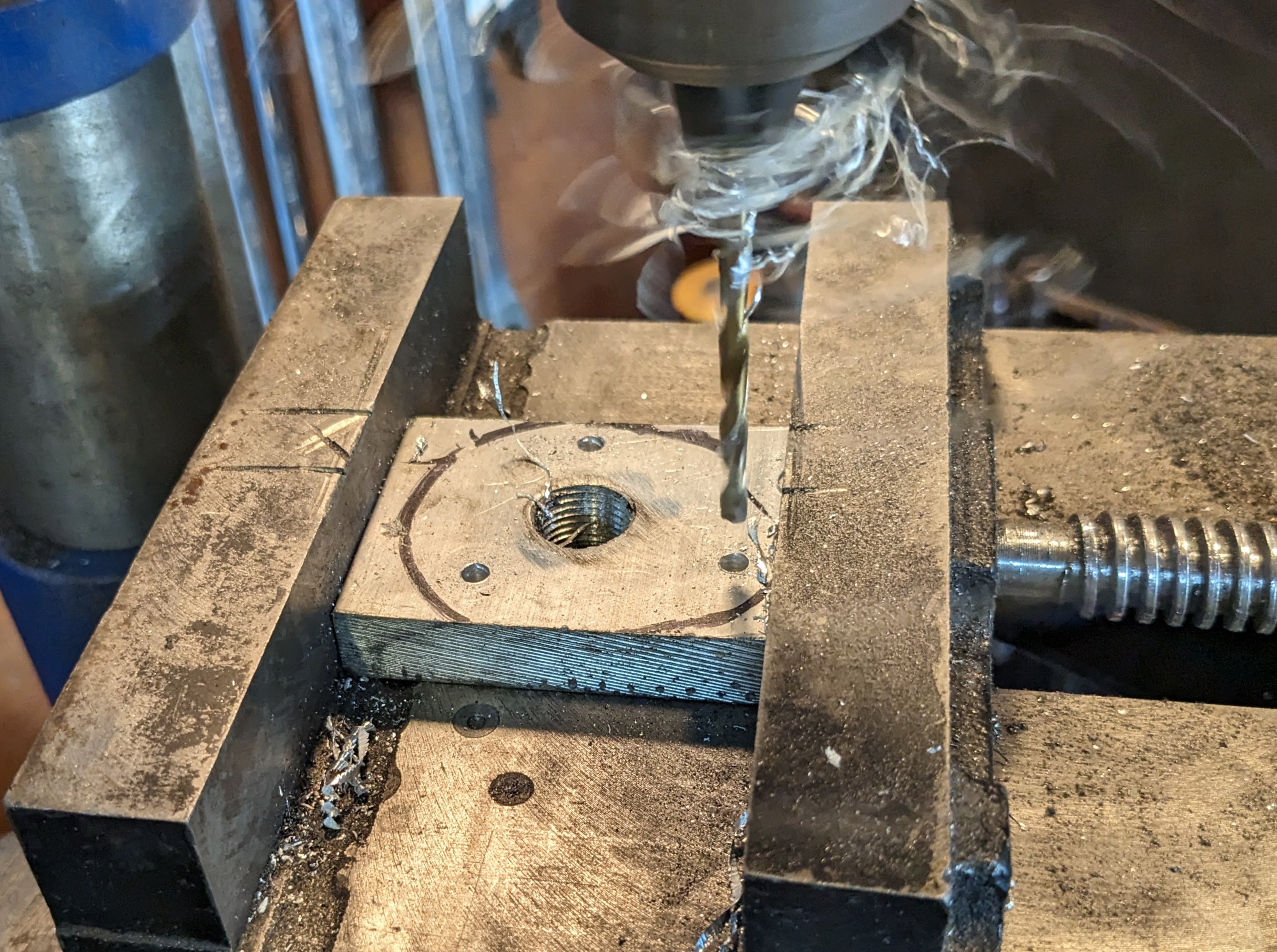
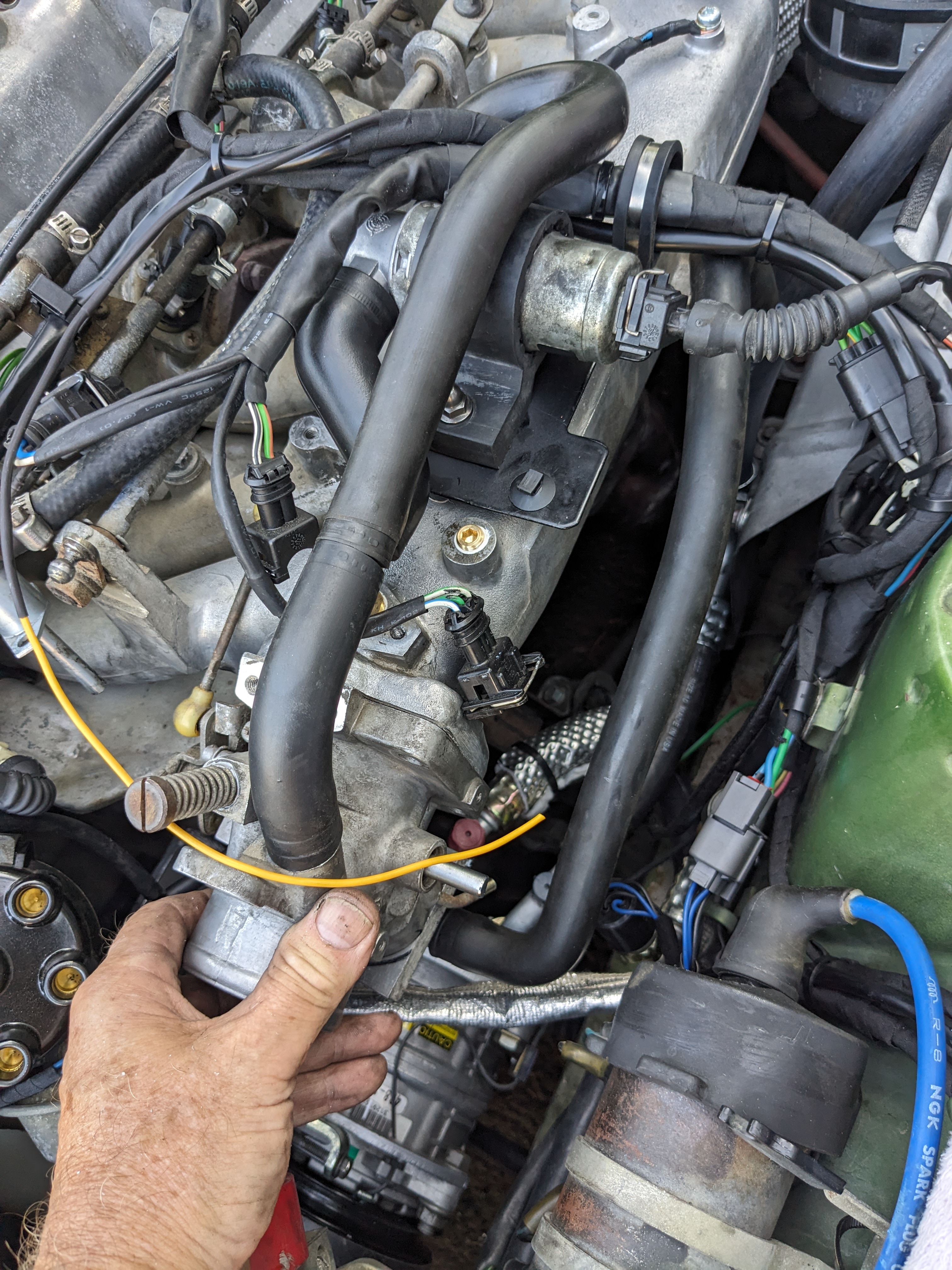
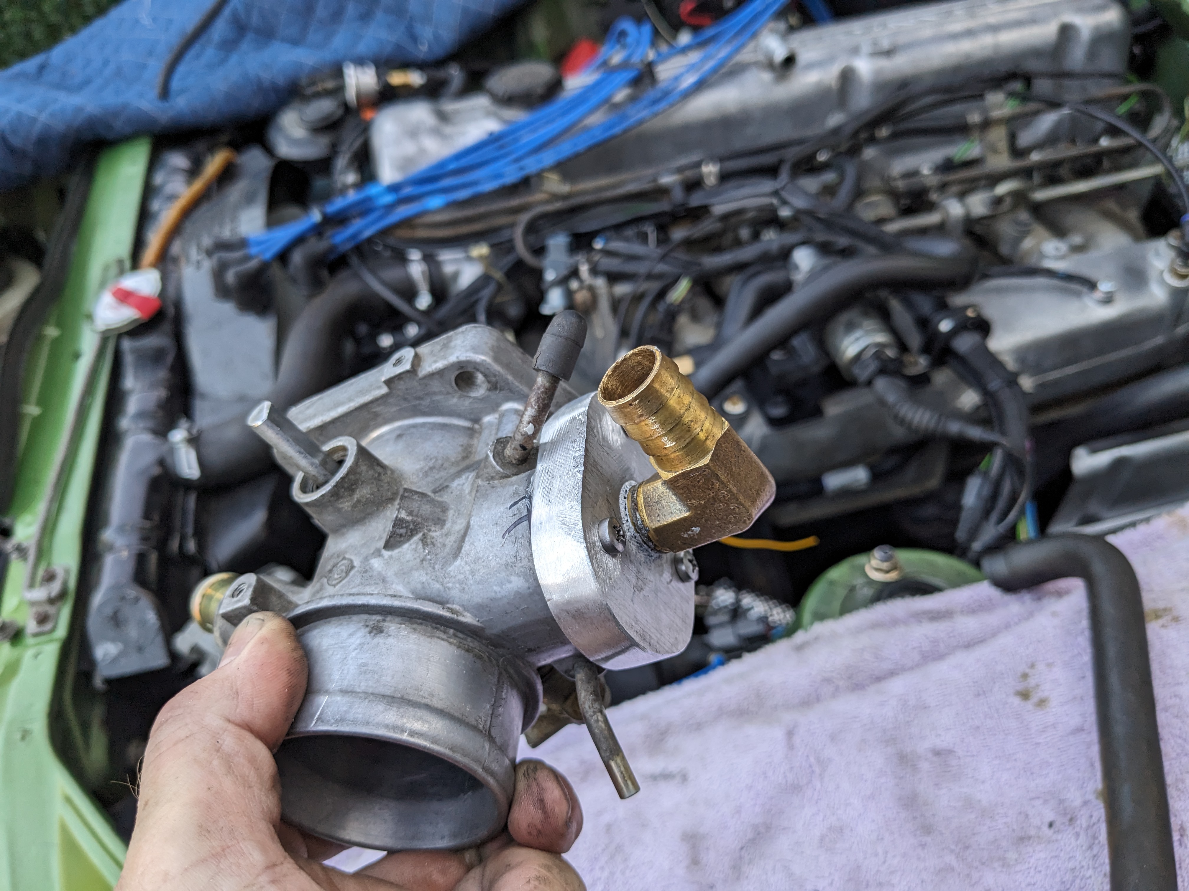
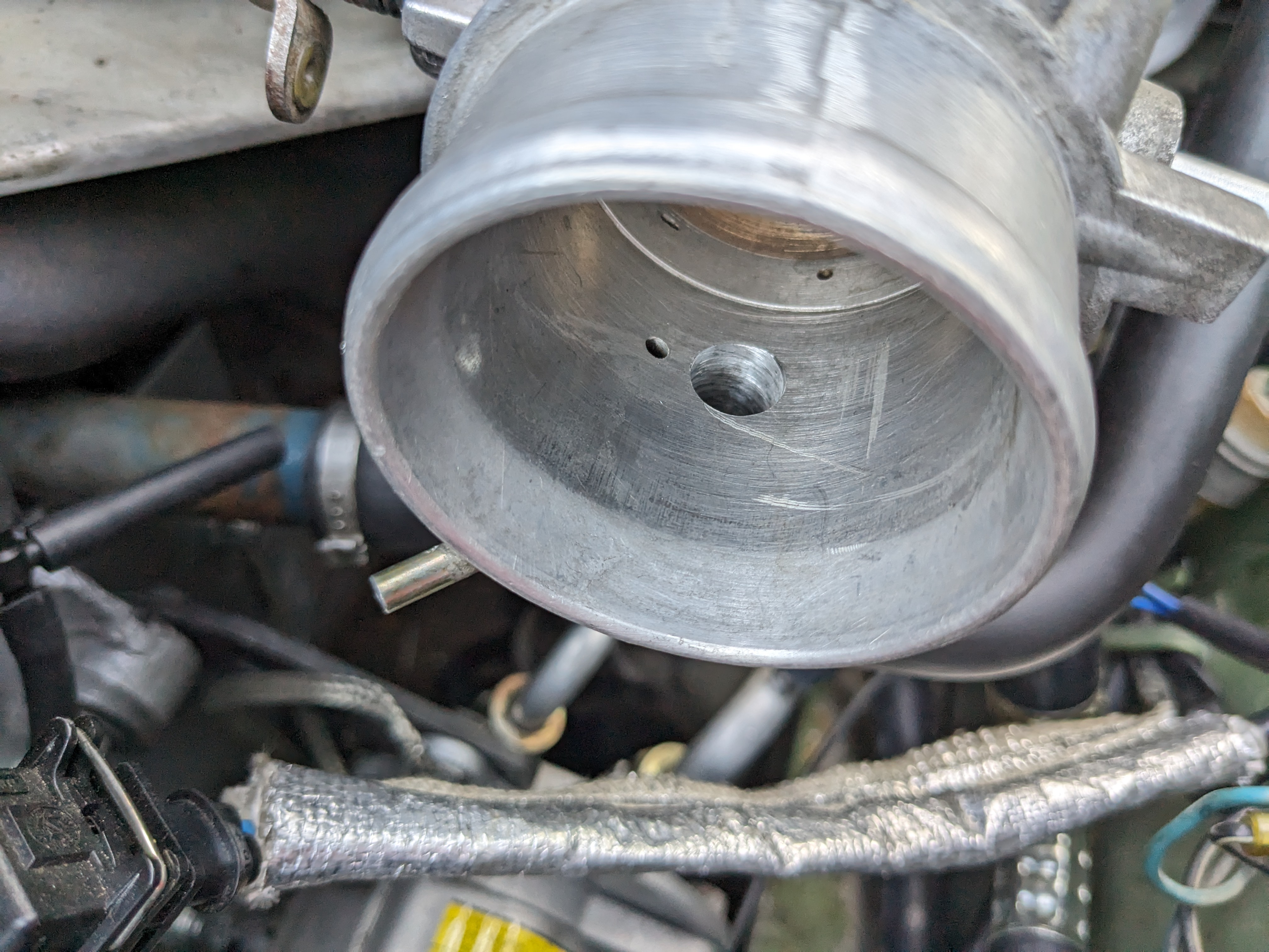
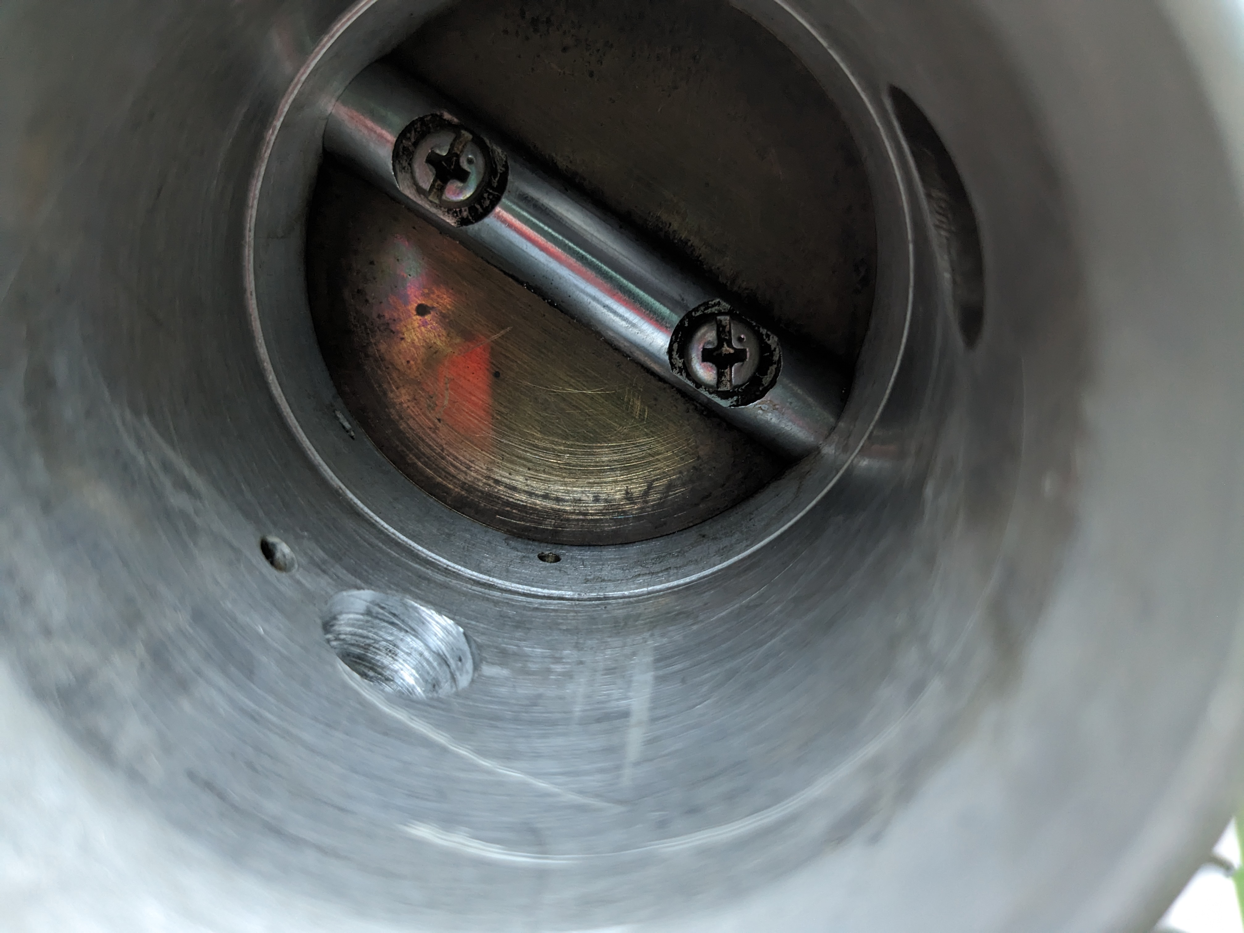
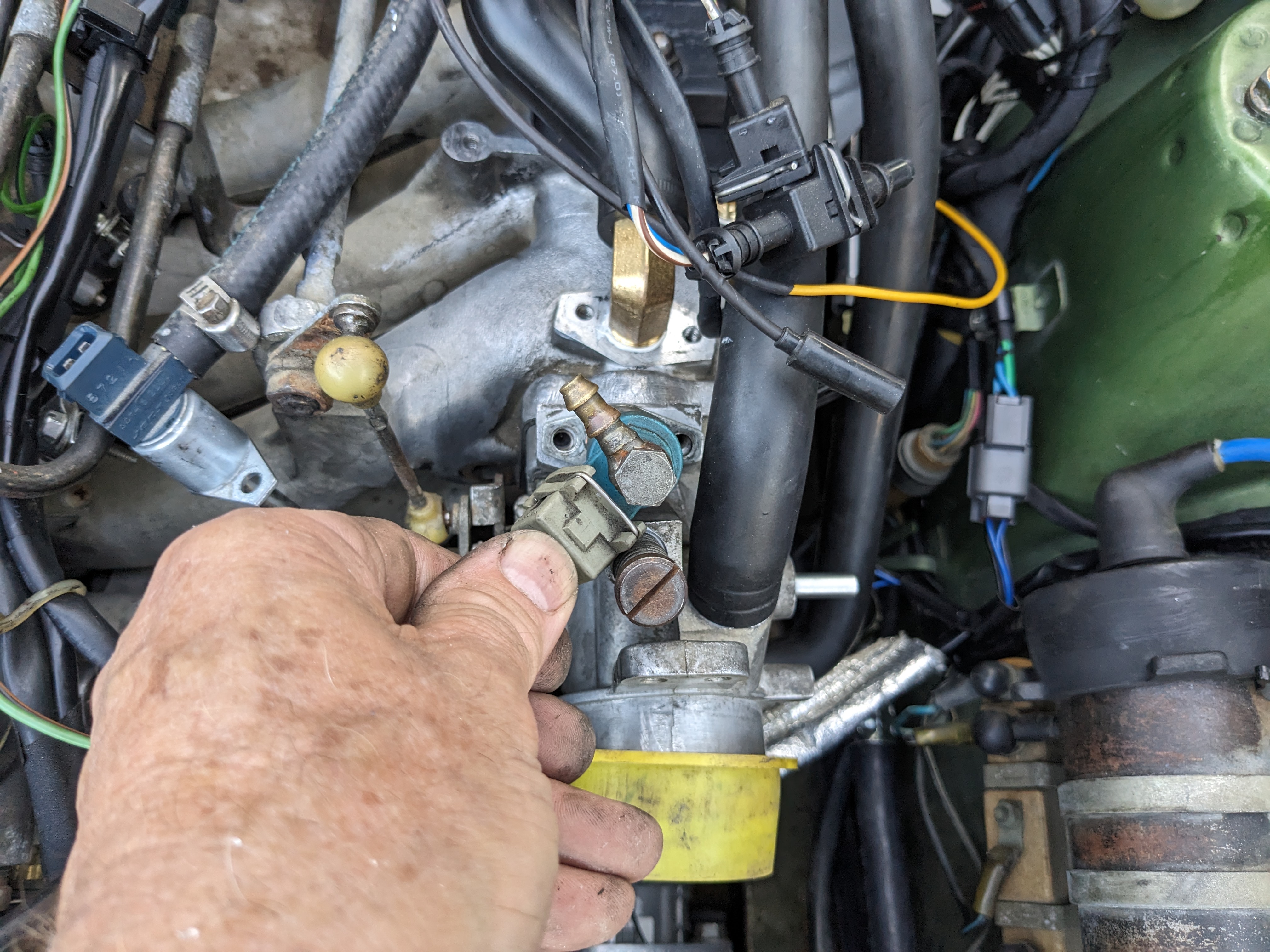
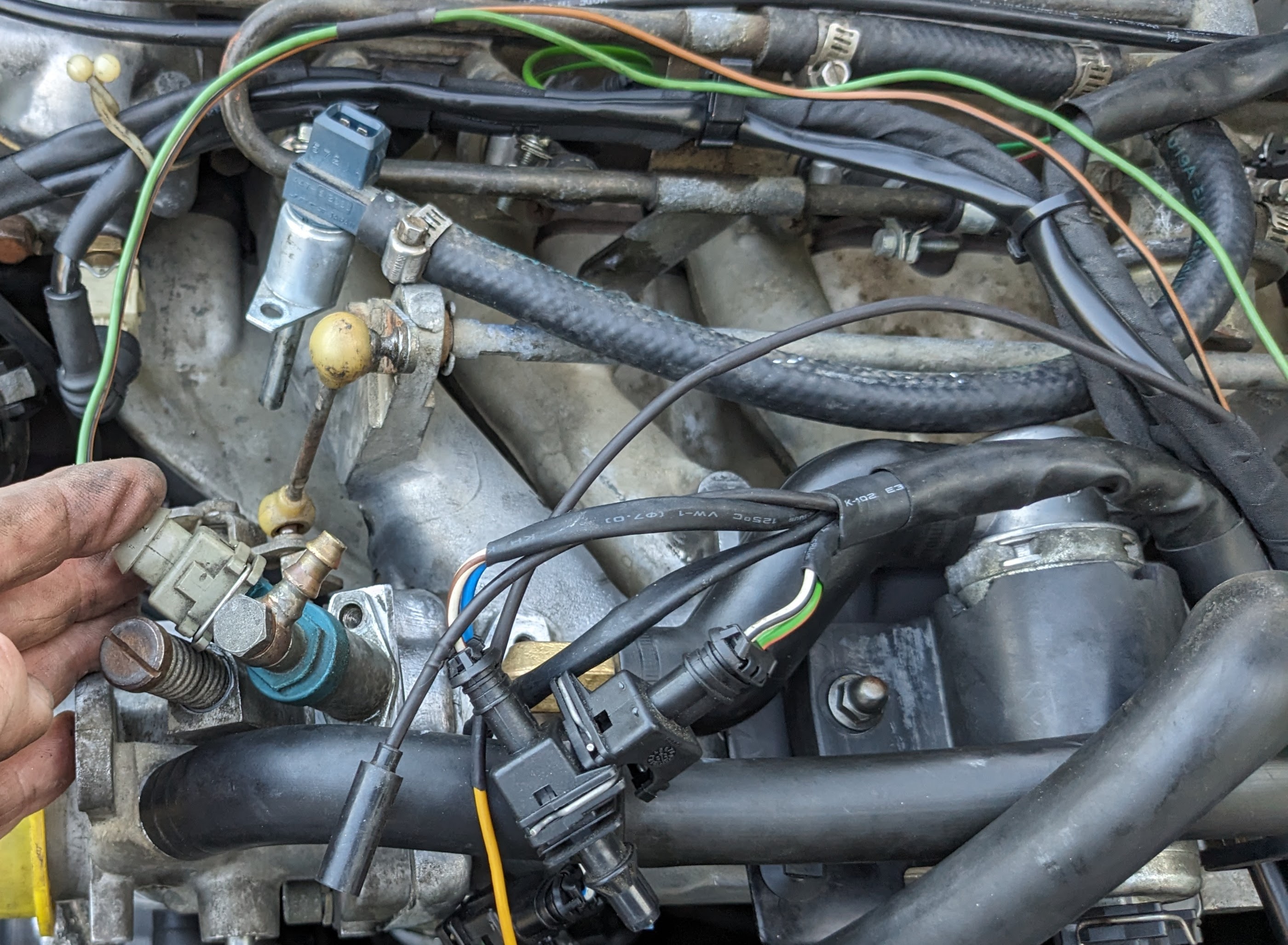
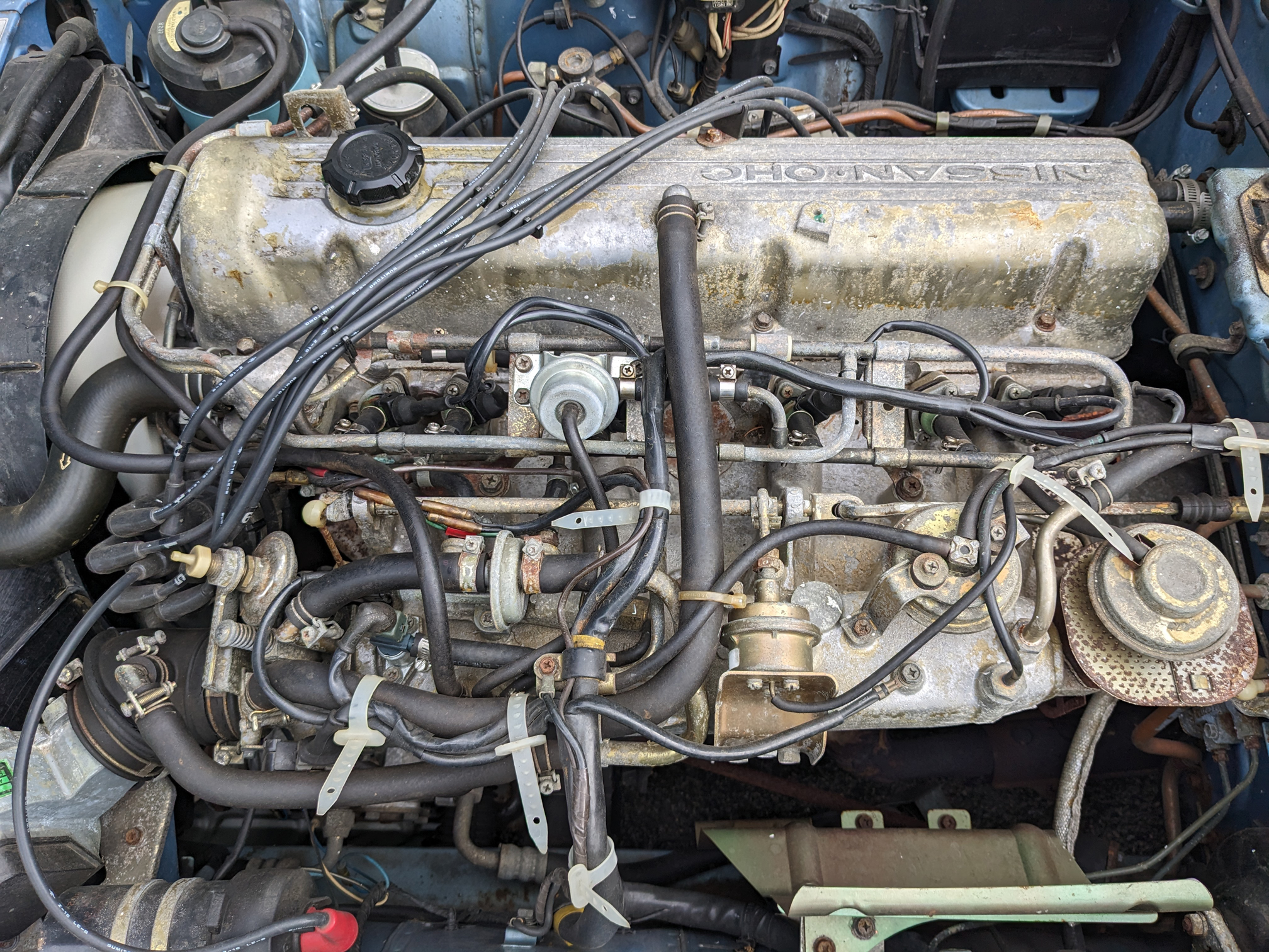
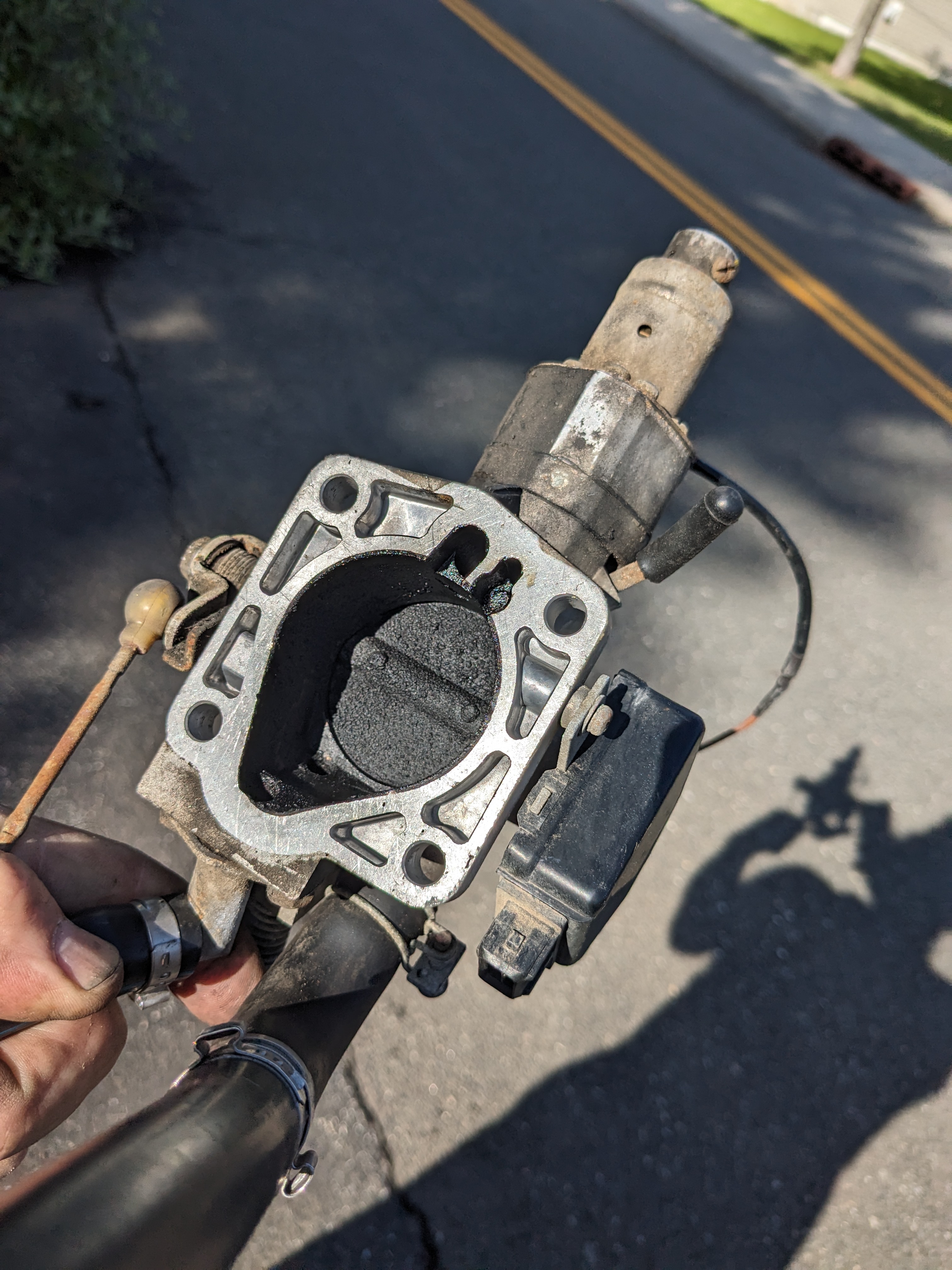
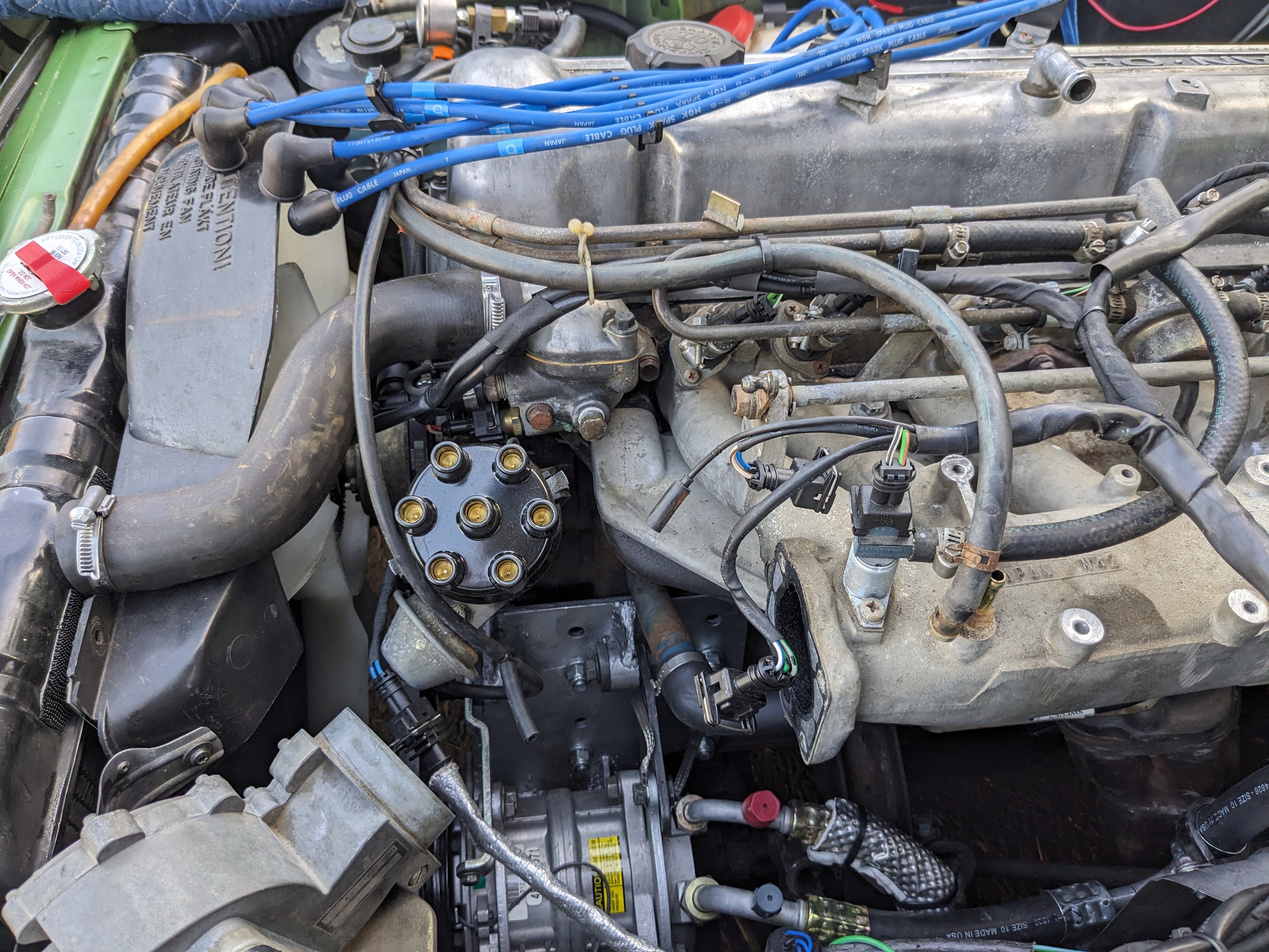
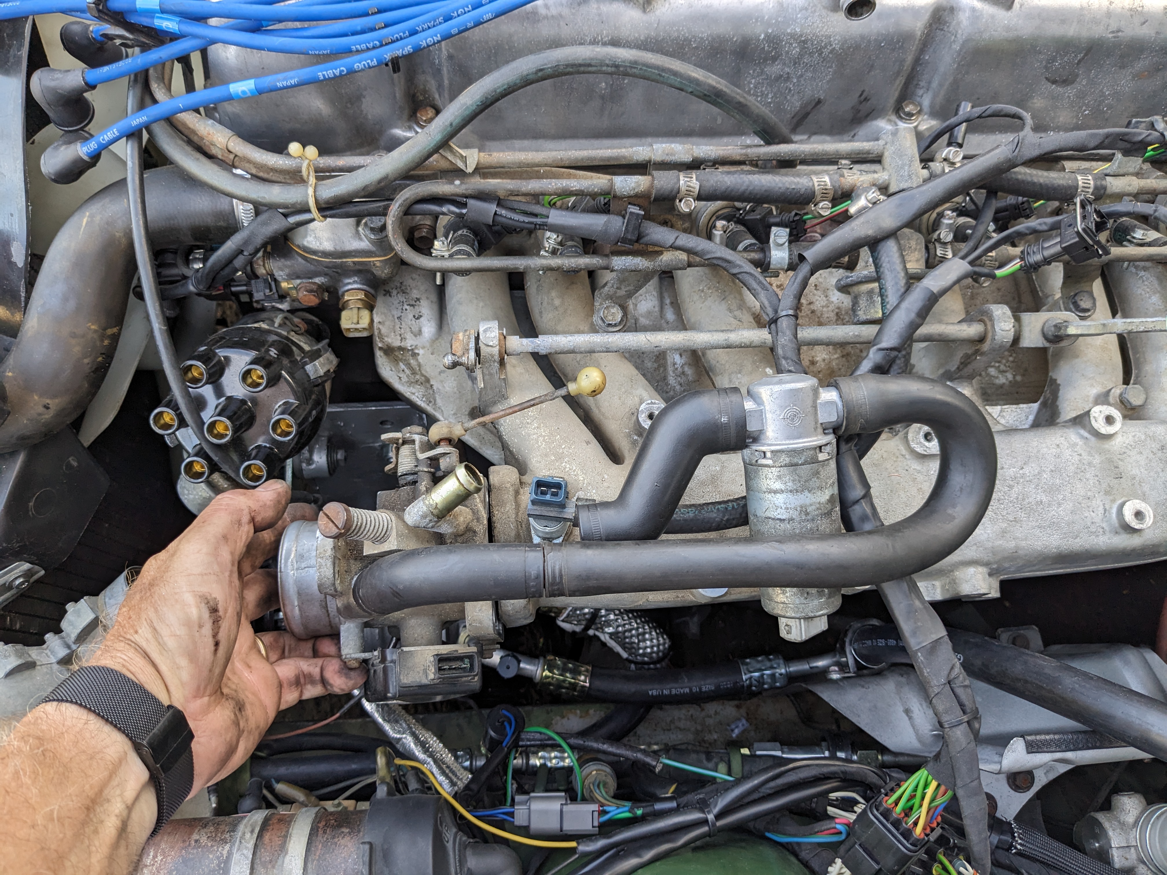
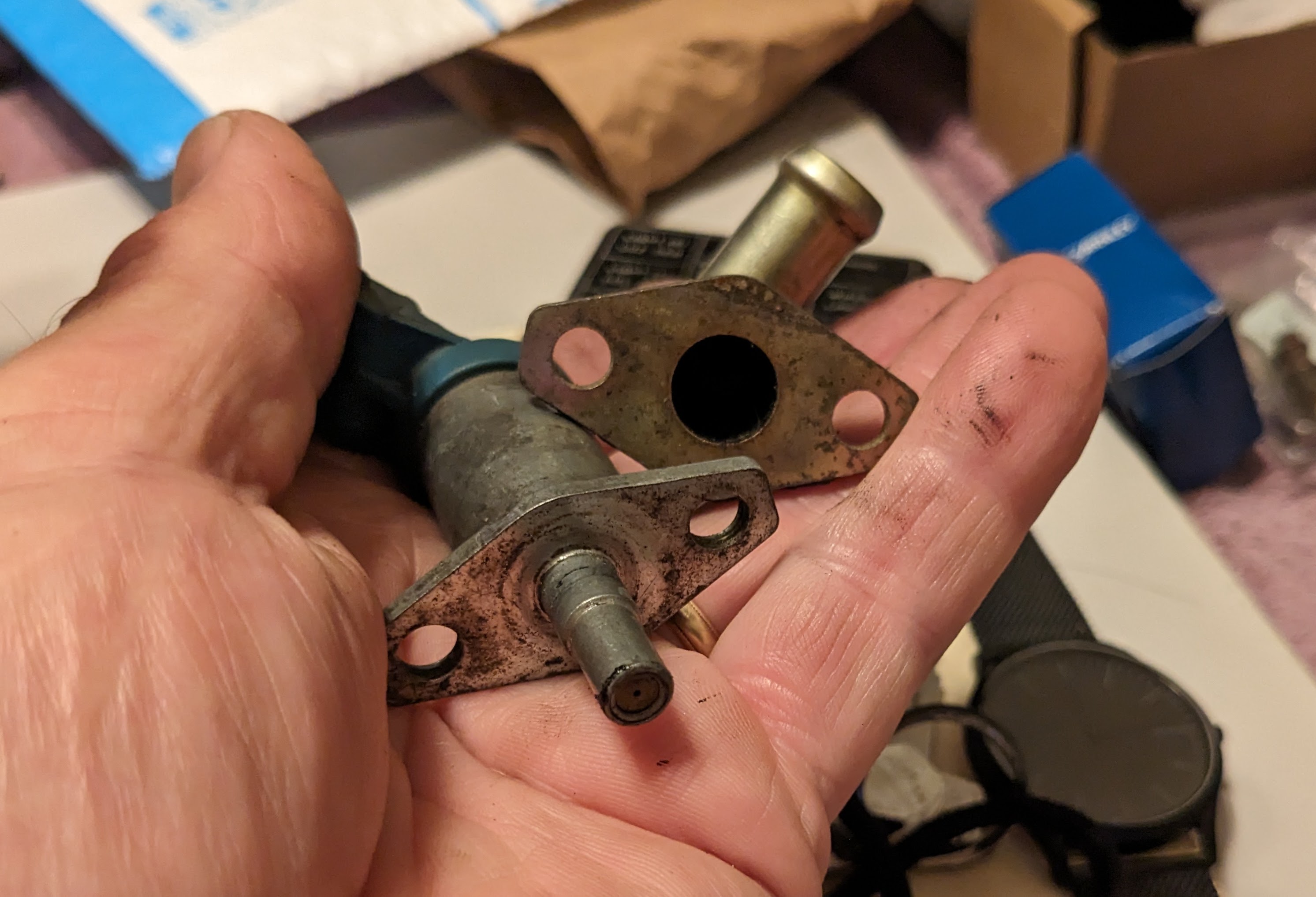
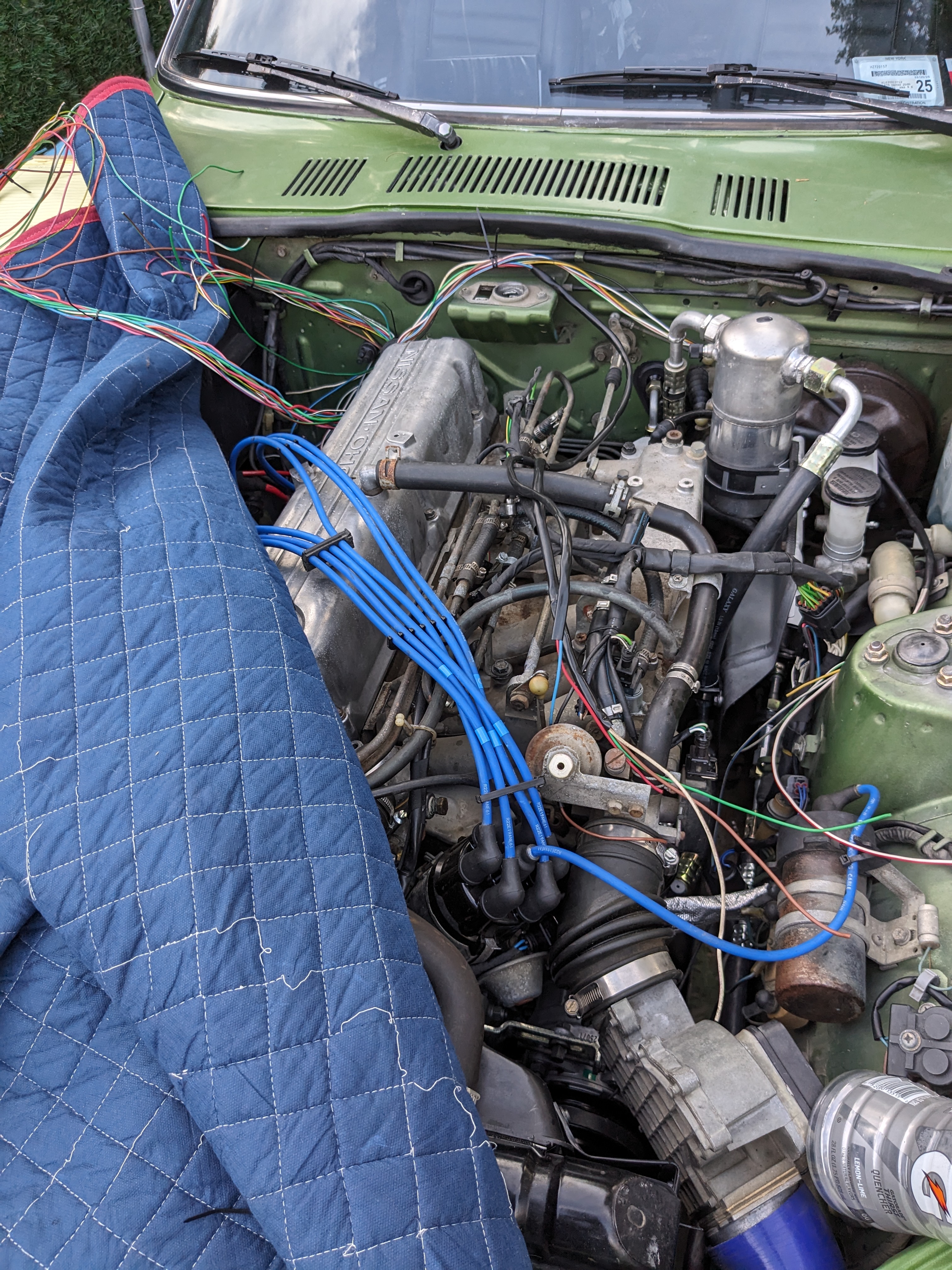
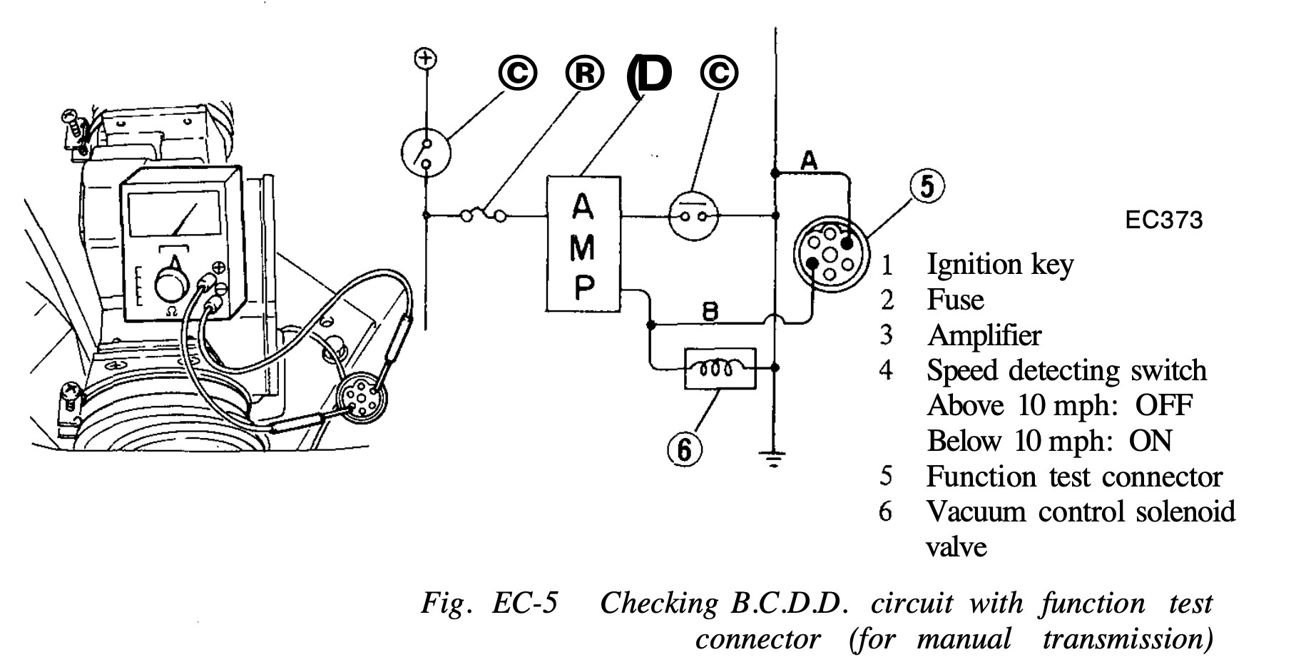
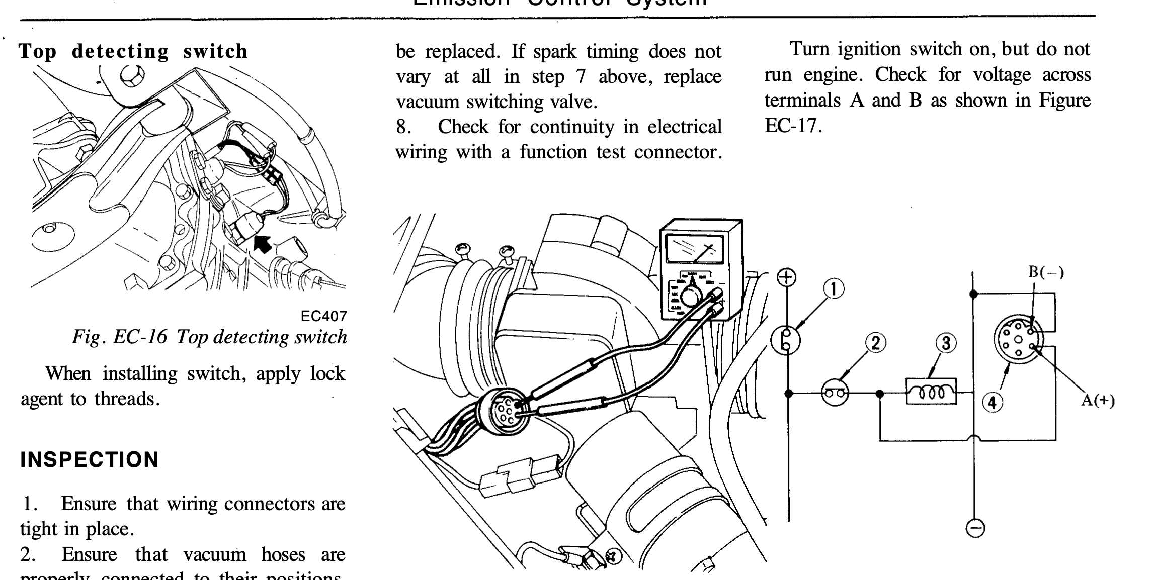
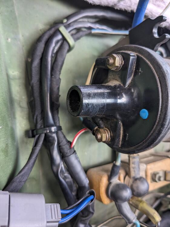
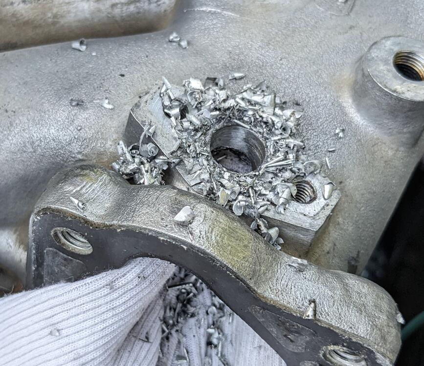
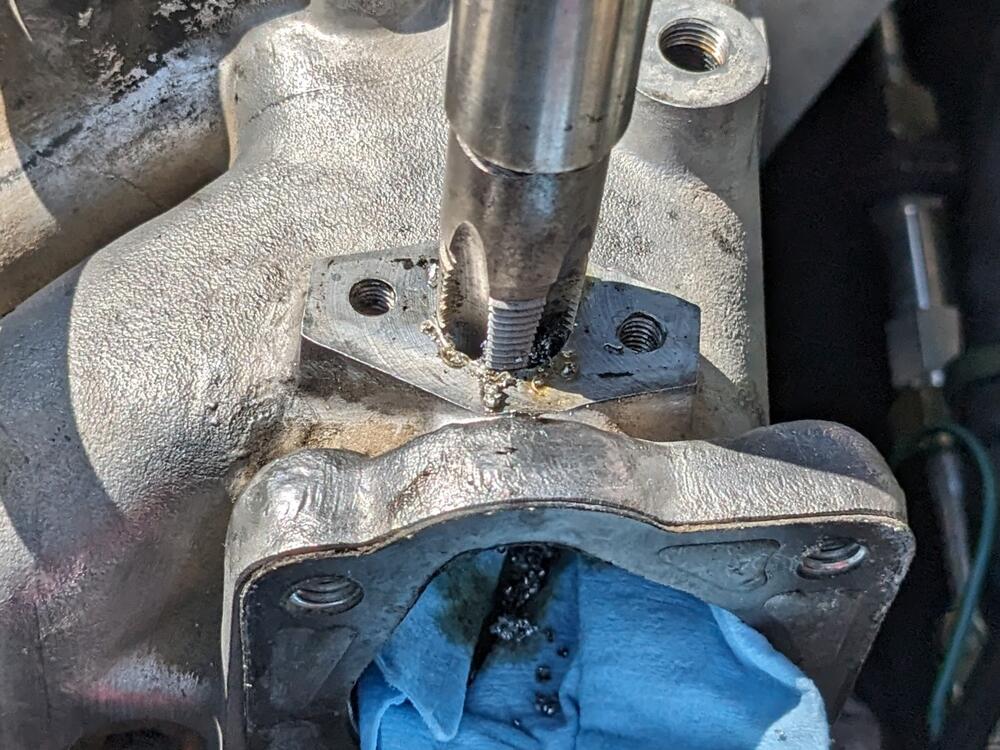
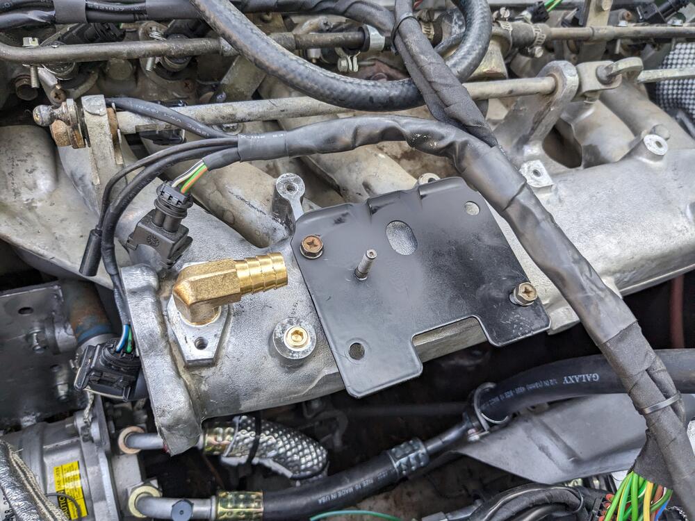
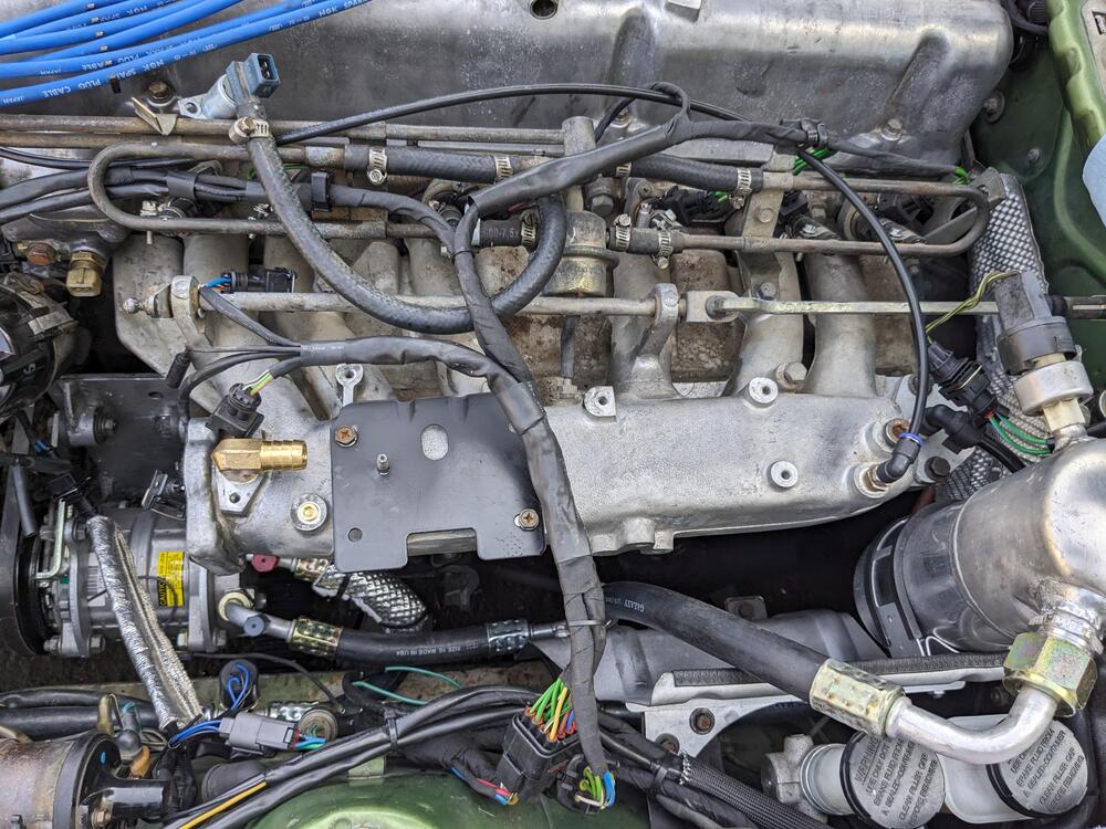
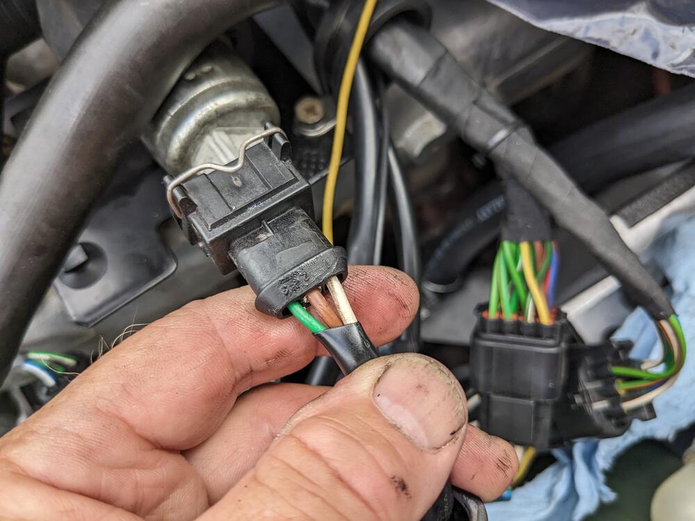
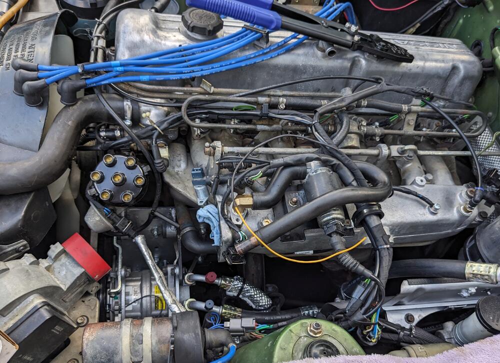
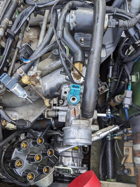
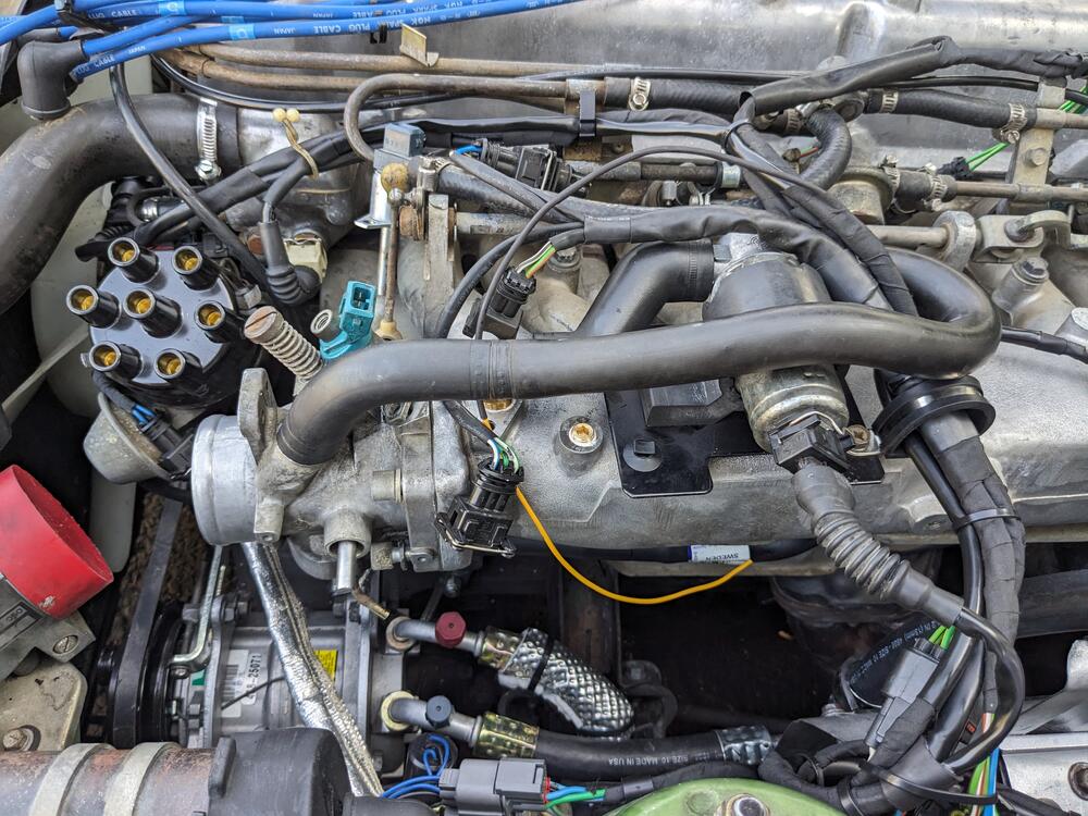
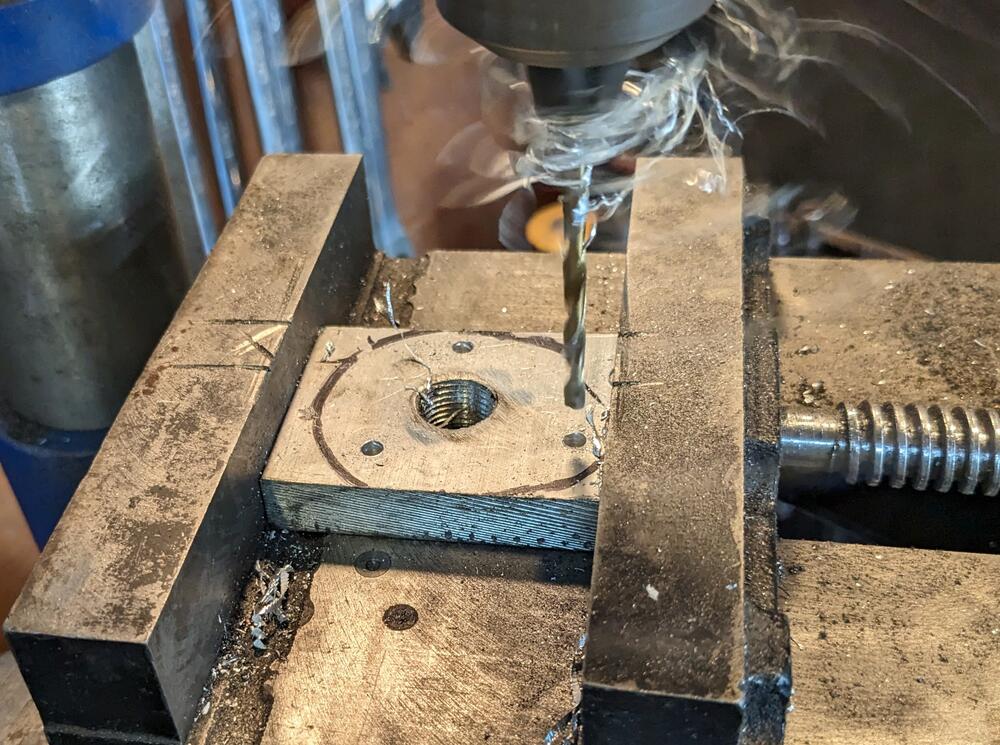
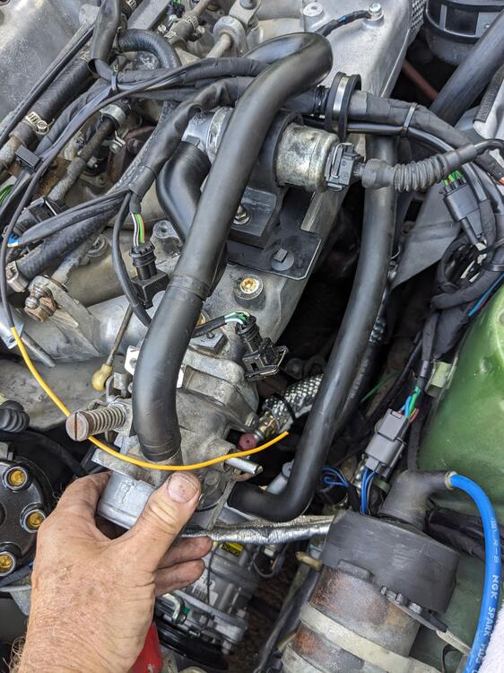
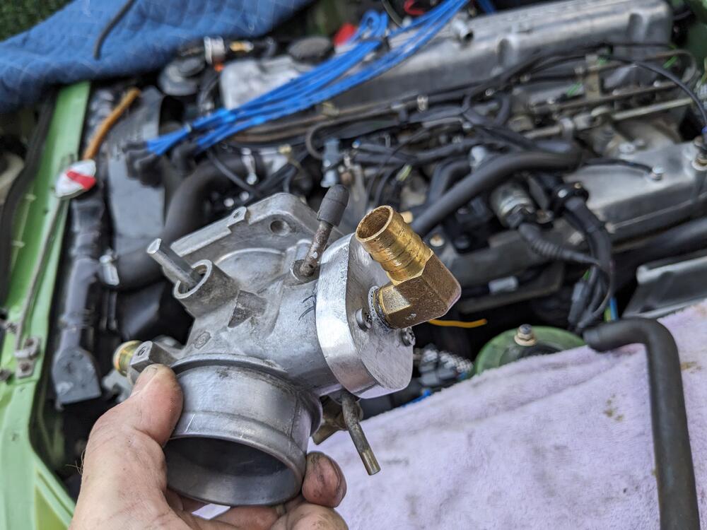
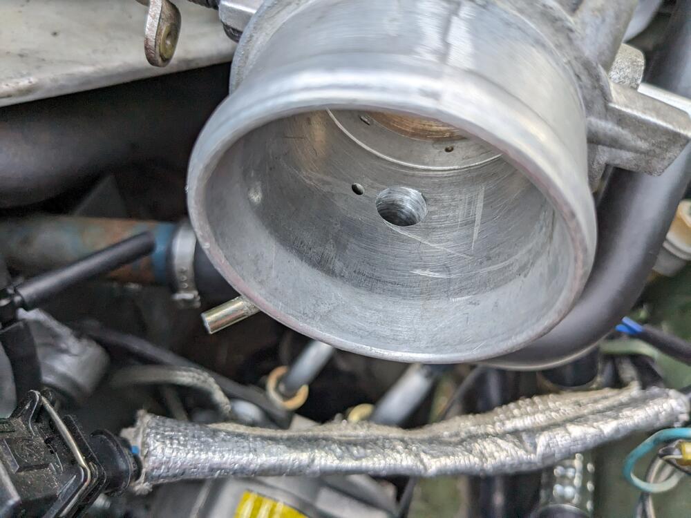
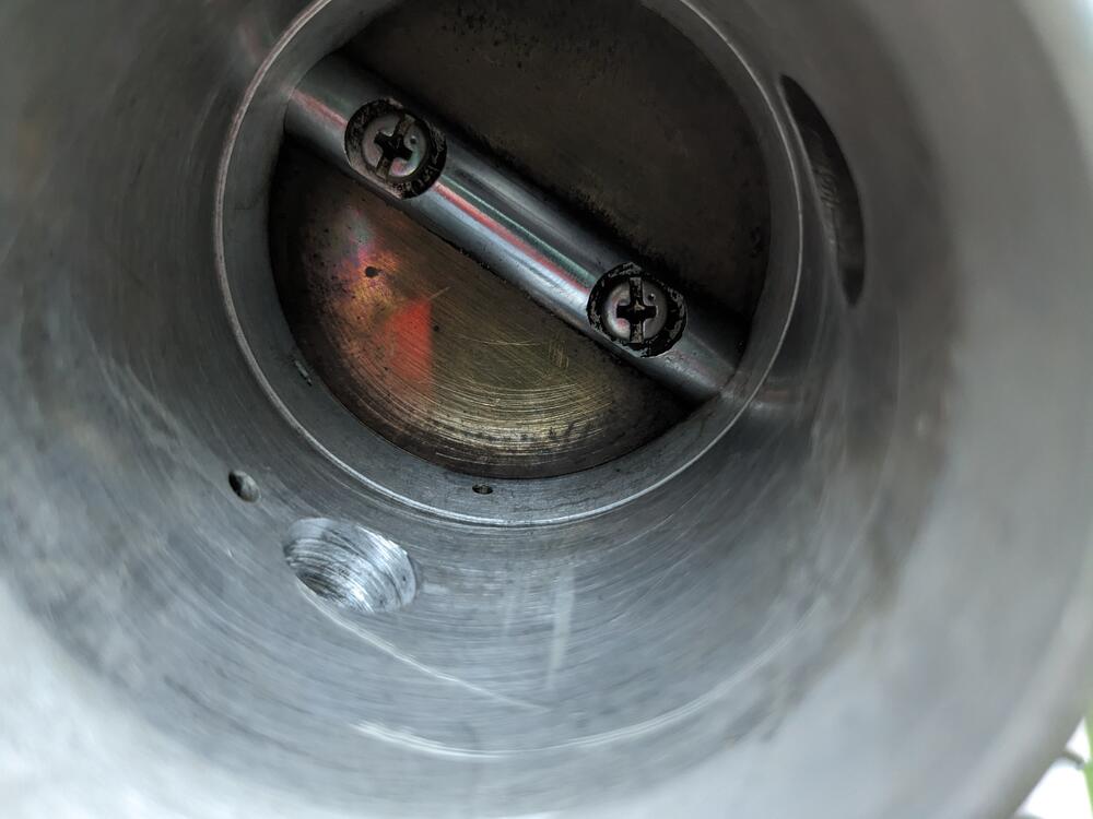
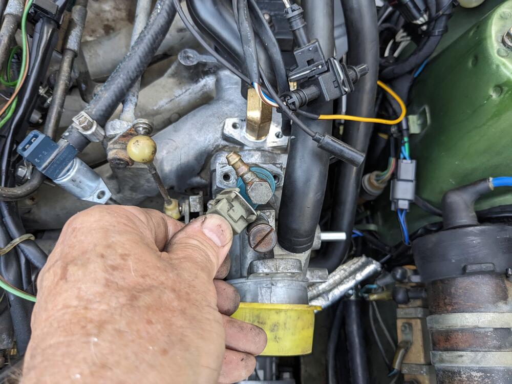
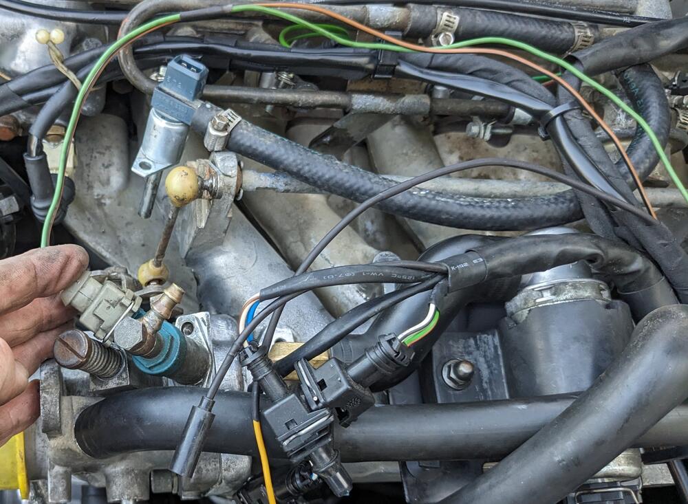
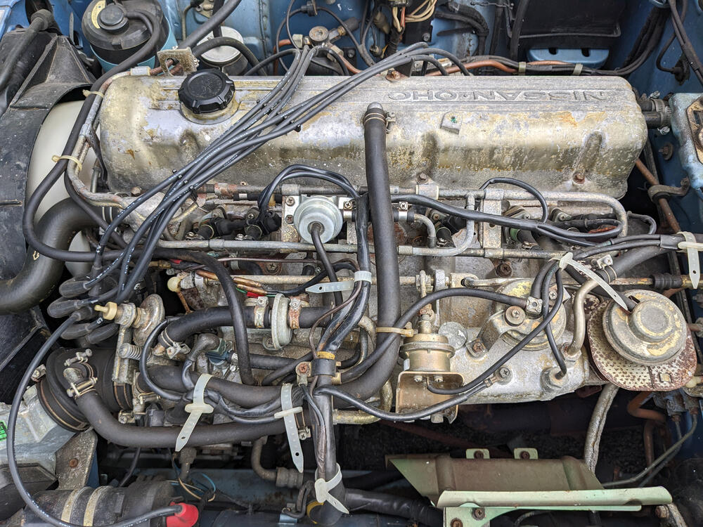
Coil (-) connection. Red-White, since that's what Volvo uses. Blue is usually (+), glad I checked what Nissan uses for (-) Drilled (9/16") & tapped the intake for 3/8" NPT elbow fitting Made a support plate for the 3517886 IACV. No room for a bolt to come through the plate from above, so I welded a nut on the backside & put in a short stud to retain the IACV bracket. Re-tapped the vacuum port for the charcoal canister to 1/8" NPT & plugged it. The IACV hose passes right over it Moved charcoal canister vacuum port to rear of plenum, using quick connect with nitrile line With the IACV placement sorted, I wired the 3 pole connection and the 2 pole for the ECT, and the ground connections at the intake CSV placement in TB to get a clean run on the CSV feed hose, I'm going to flip the CSV. Converting to barb fitting. Using a different CSVB than above, I have 3 (Volvo) variants with differing offset connectors Made the block off plate for the B.C.D.D, with 3/8" NPT port for the valve cover vent. Used the B.C.D.D base gasket as the template for the mount holes shaped somewhat, brass elbow fitted. Used HondaBond to seal the plate to TB. B.C.D.D port redrilled to match the greater breather vent ID above, since the above port is now dedicated to only idle control Breather vent elbow fitted below will clear the TPS once reinstalled. Have to figure out a clean way to unify the valve cover port hose with this 78 280Z AAV & Breather vent hose layout for ref.
-
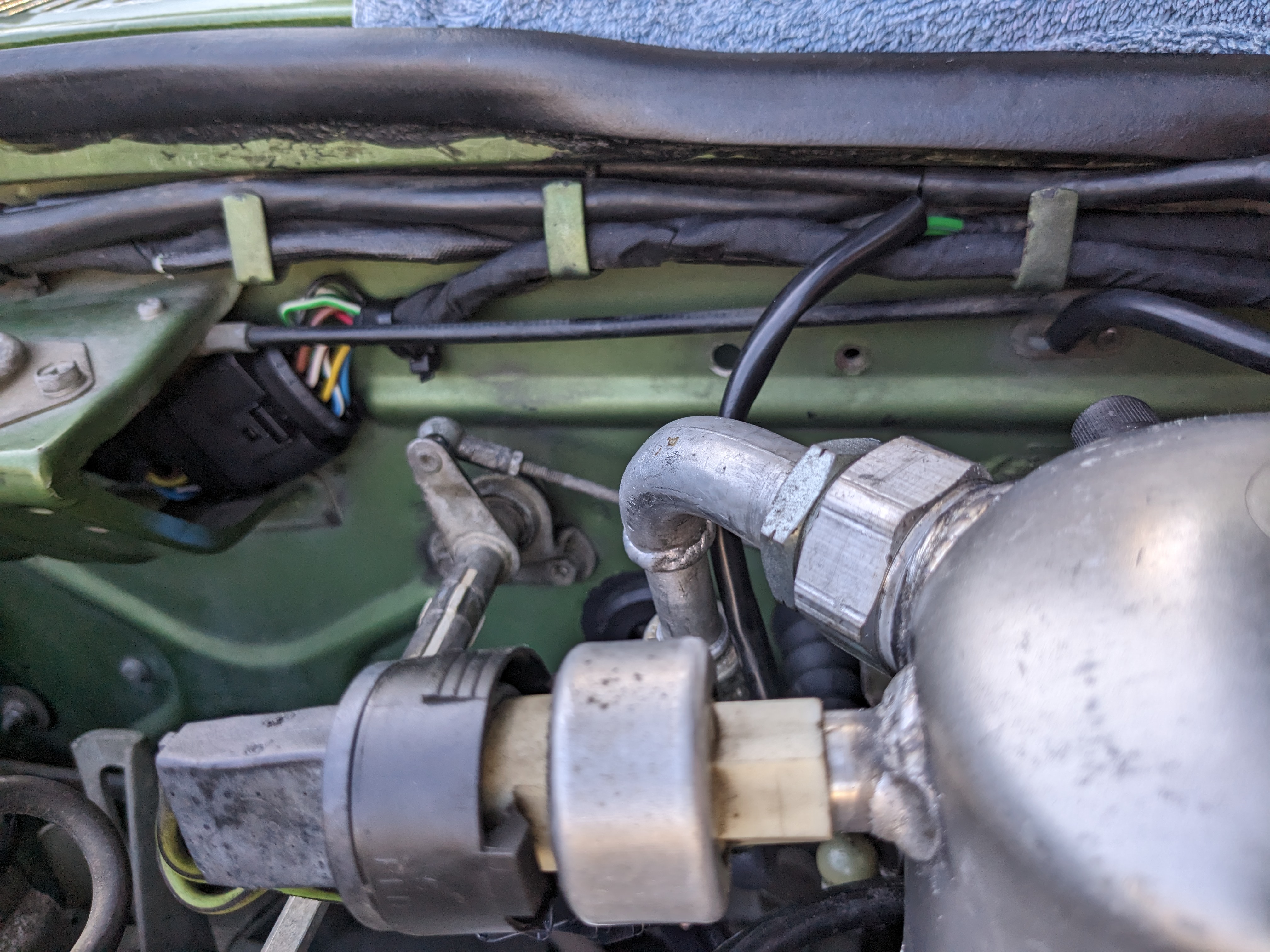
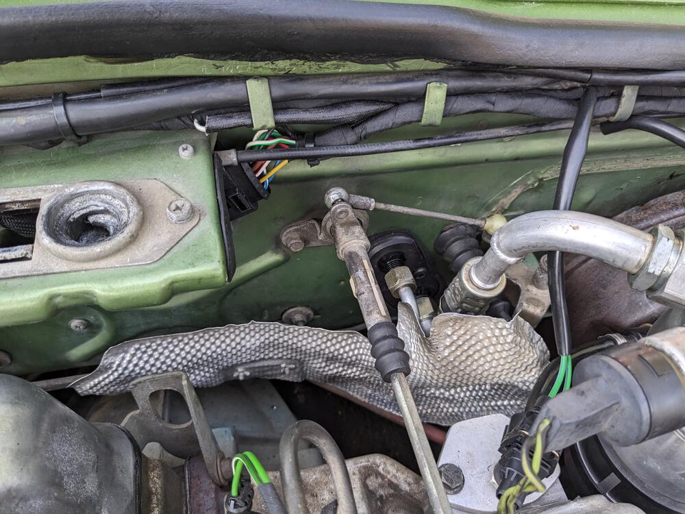
Added a heat shield for the AC lines
-
I'll start with just the standard mixture adjustment, don't want to mess with the clock spring unnecessarily. I read that long thread on the pro & cons of messing with that...
-
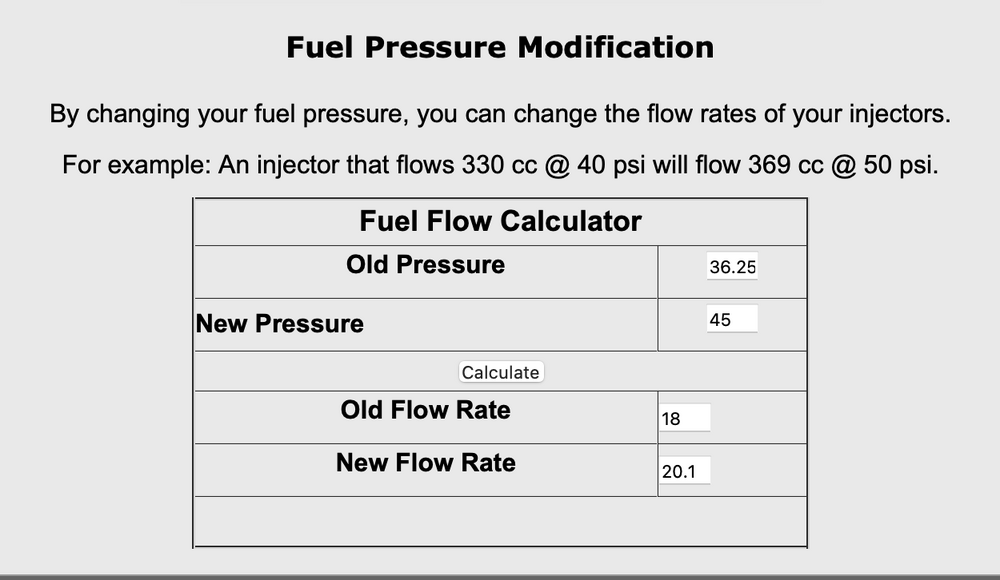
Since I need to pull the rail to replace seeping fuel hose, I'm thinking I'll just switch to the 3bar FPR (Volvo/VAG style) and keep the current injectors. It's "only" a 2psi difference, assuming mine are even flowing the spec 17.9lb/188cc. I need to revise the delivery to the rail in prep for the V6 conversion anyway. If I recall, the AFM can be tweaked to increase/decrease fuel volume. I recall on the Fiat (which had the same system) that was a thing. I'll have to research that on here, I'm sure someone has played with it. I'll start will just the mixture adj., since that may be enough. I'll have the WBO2 on there, so I can monitor actual AFR's.
-
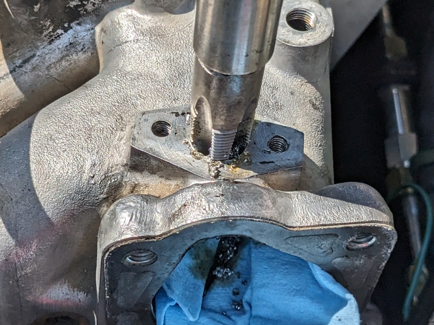
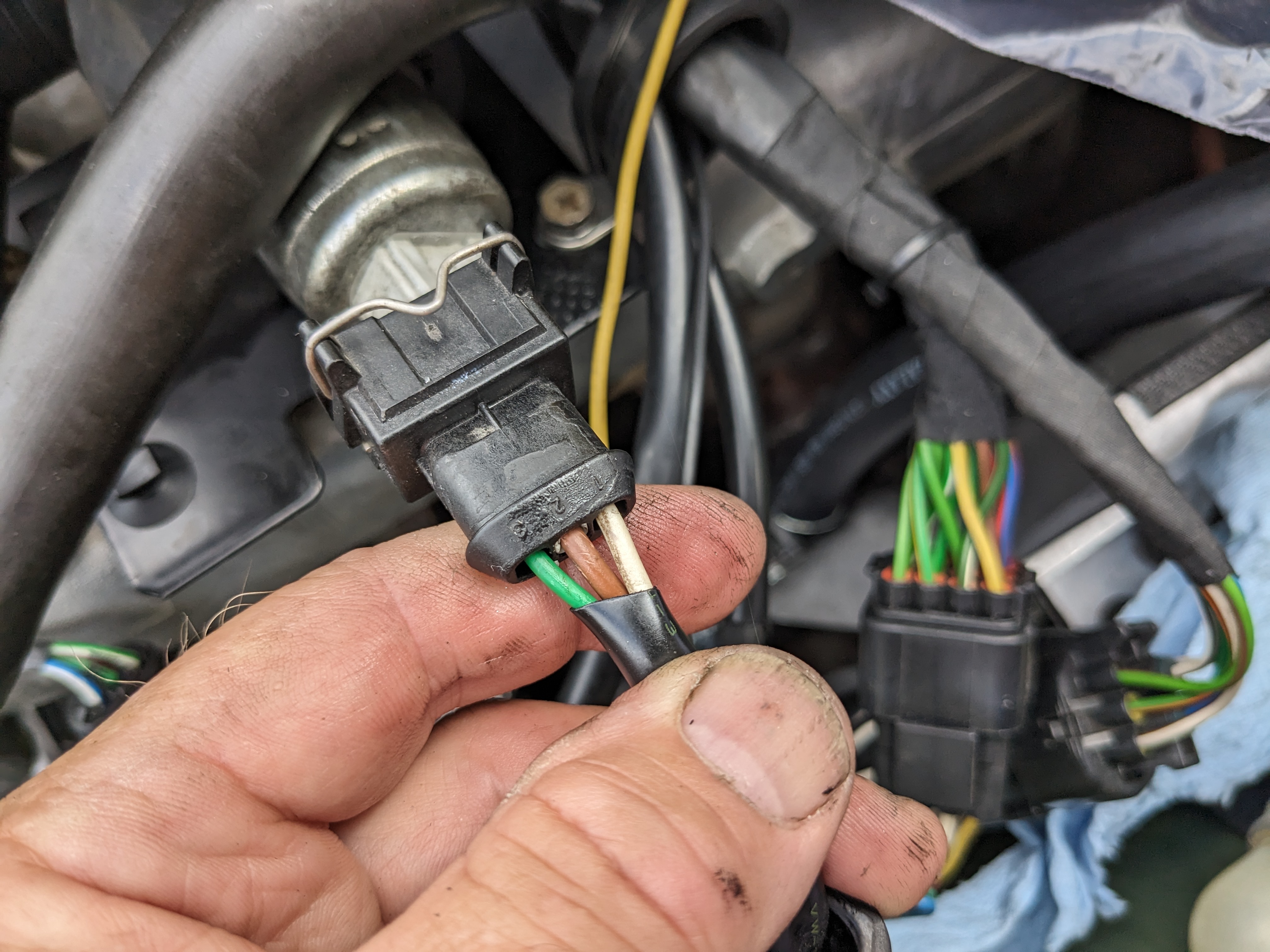
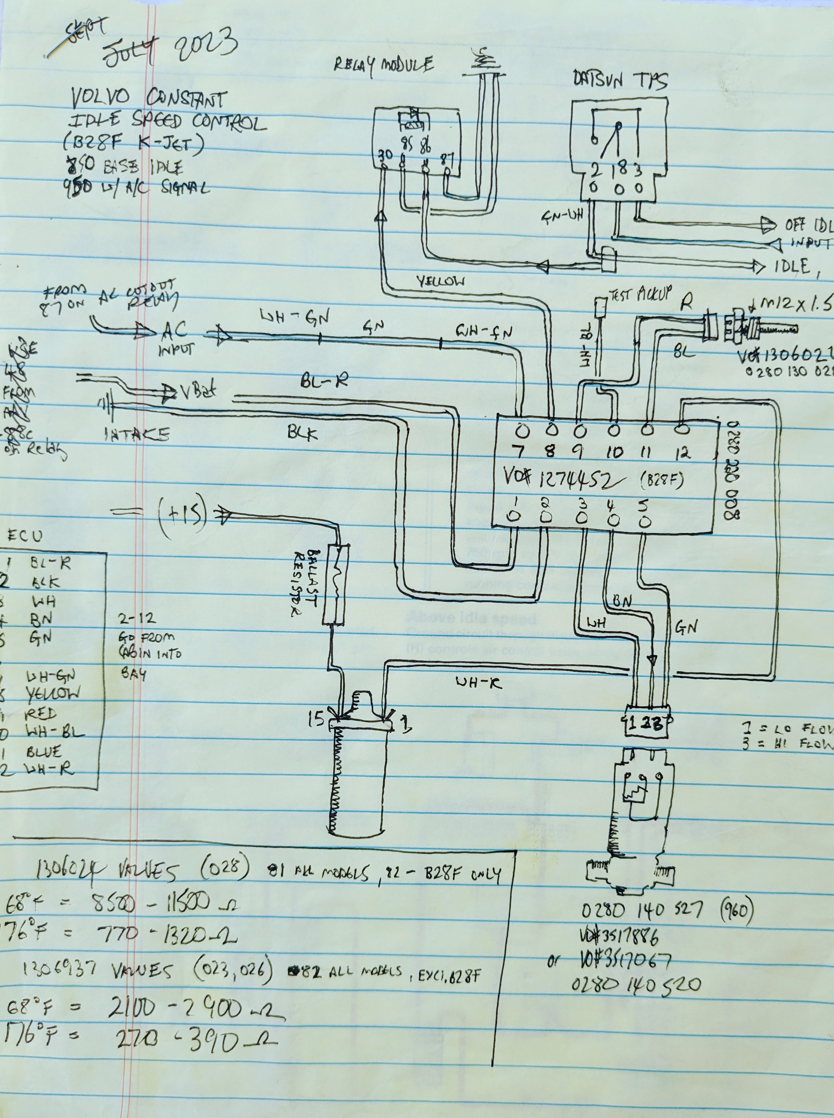
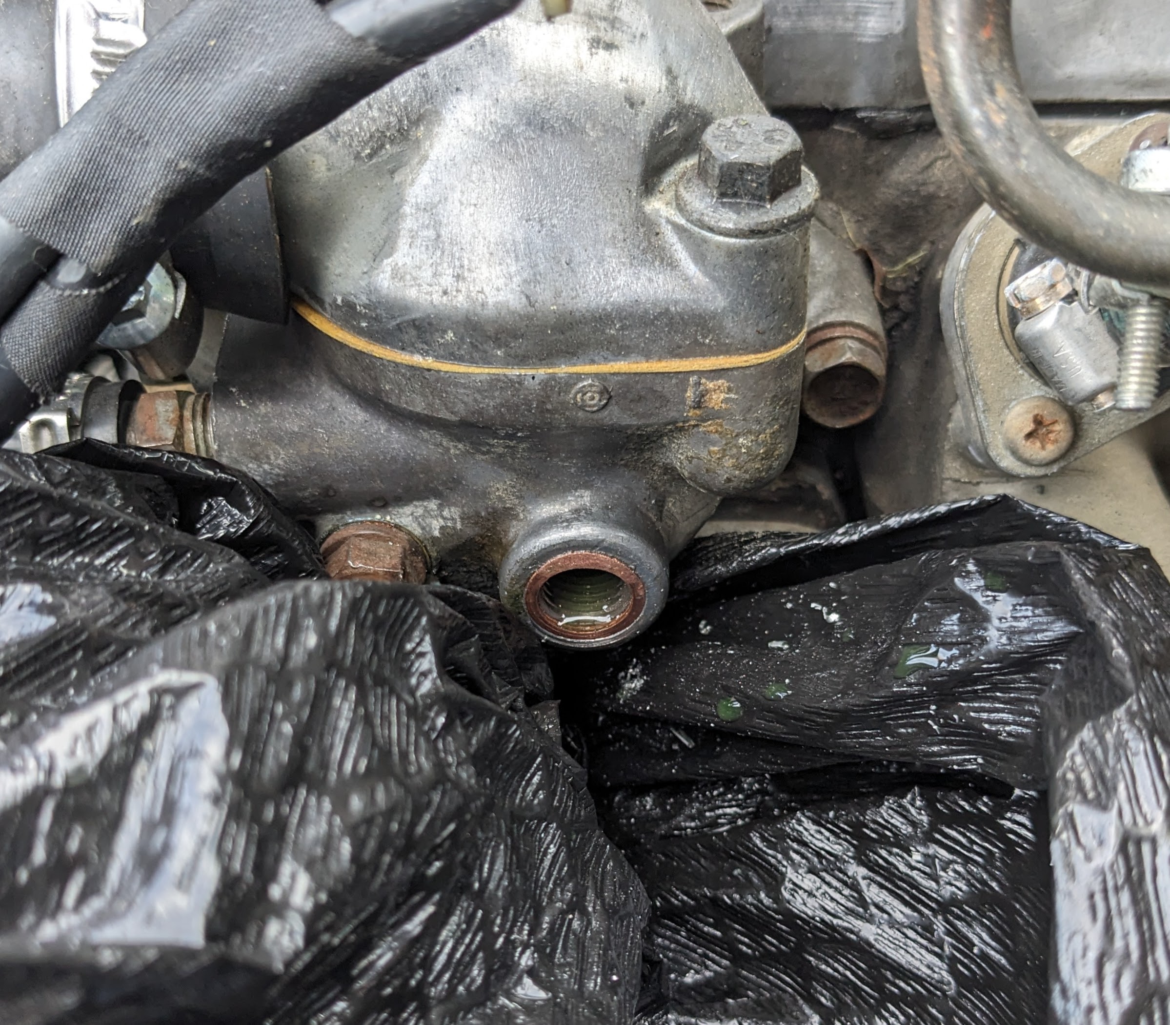
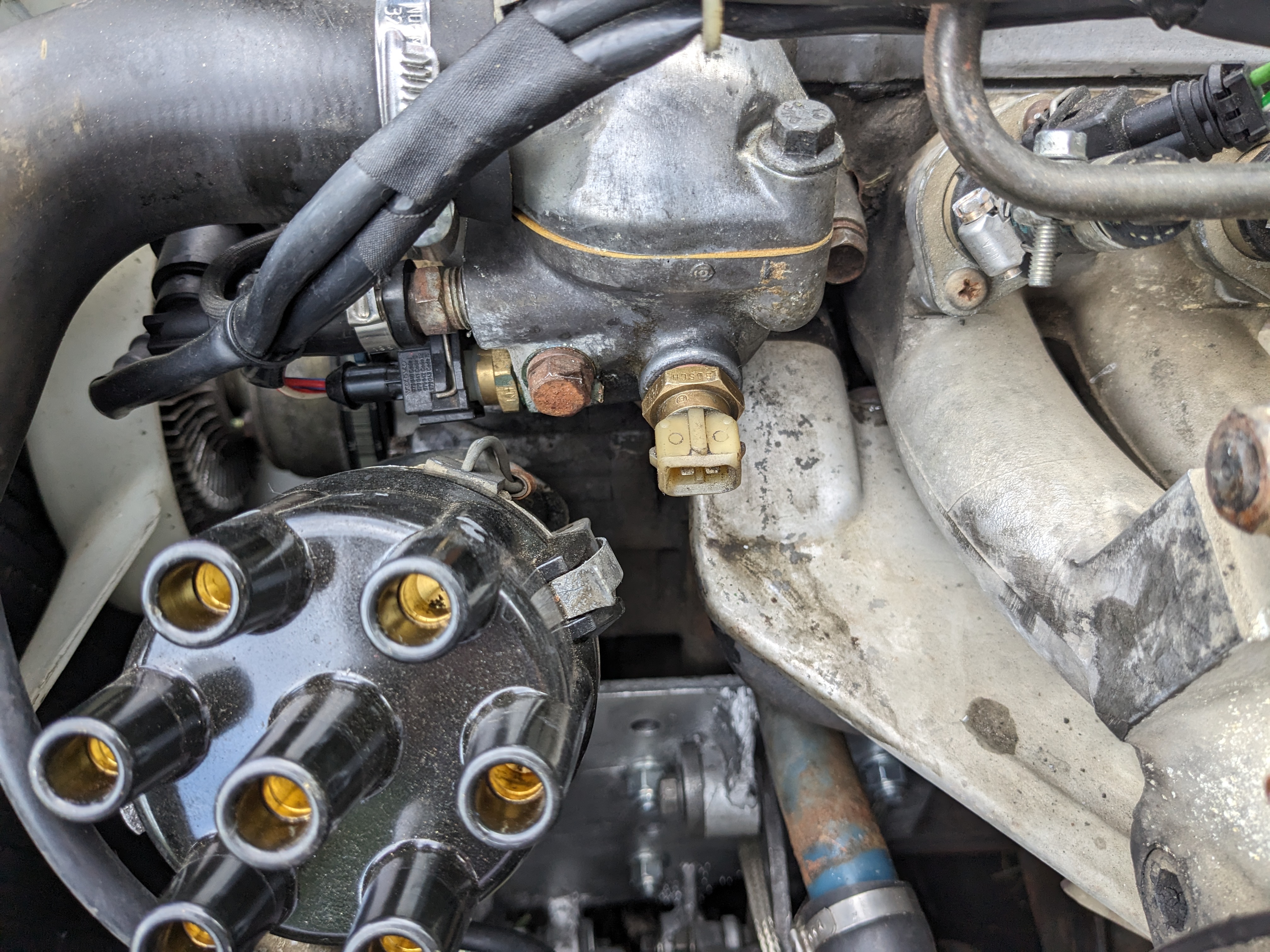
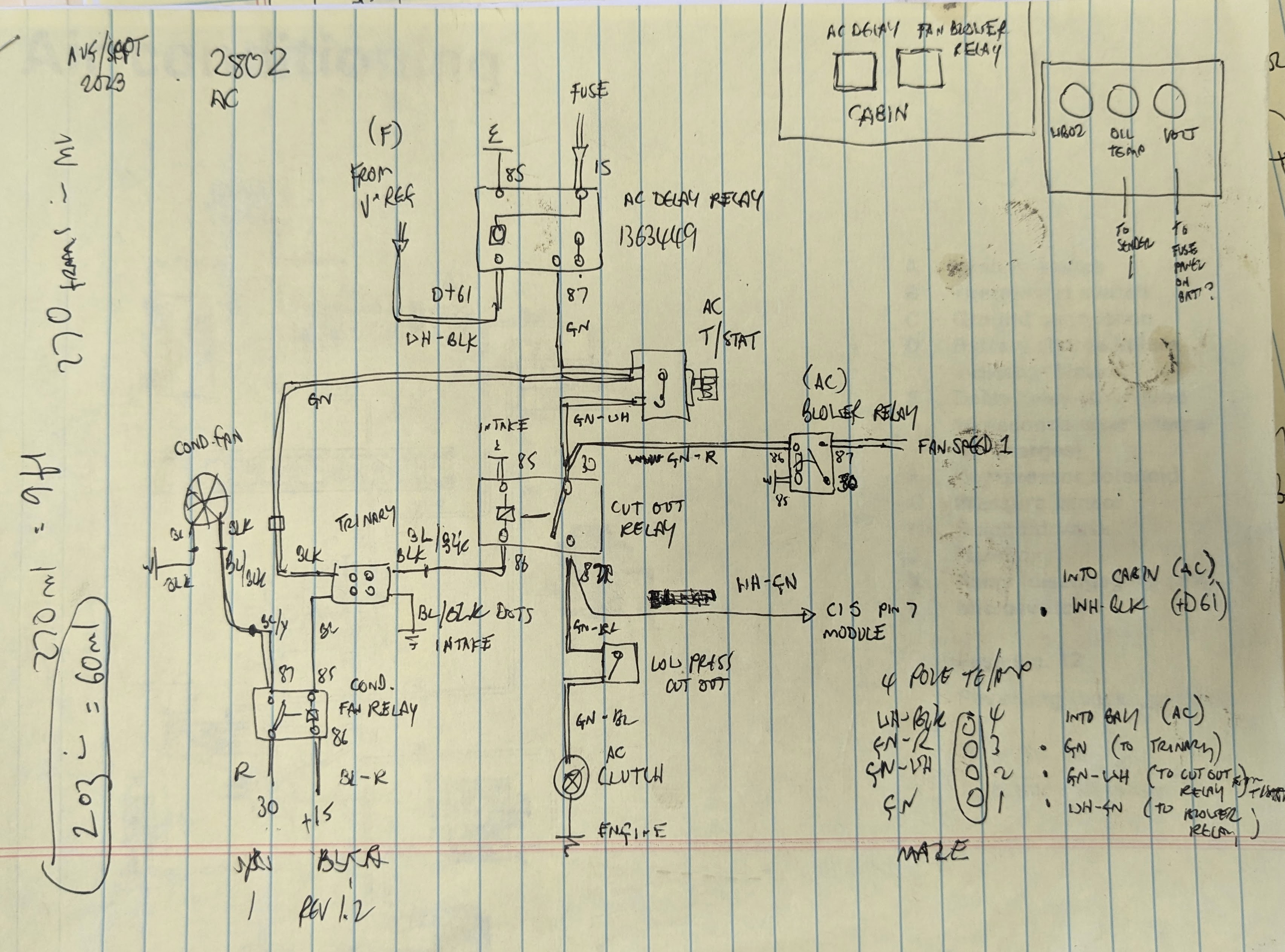
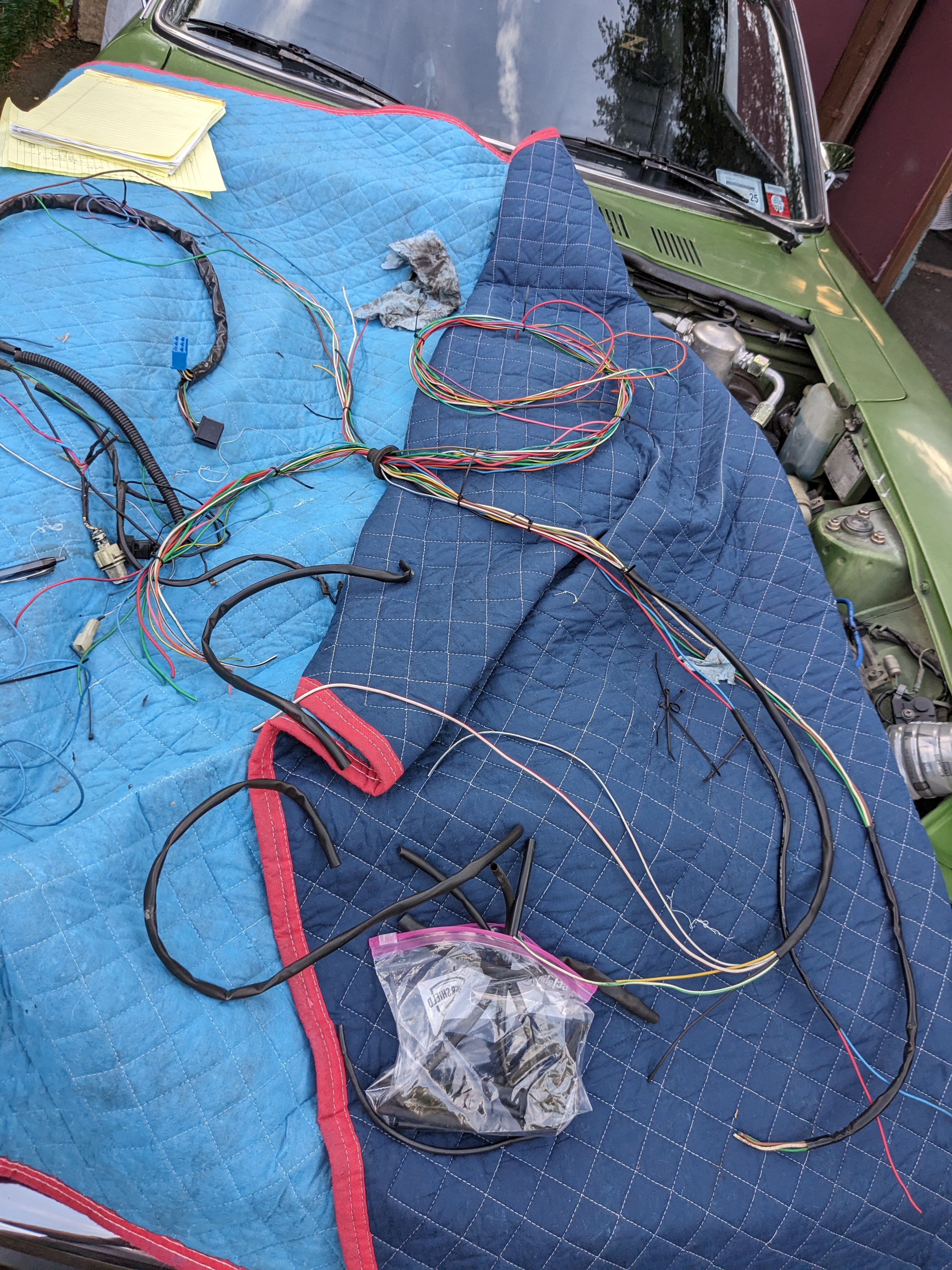
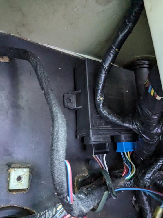
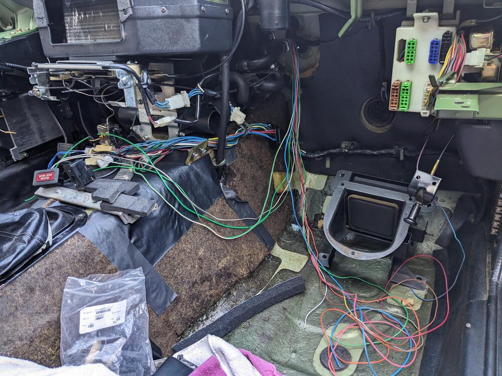
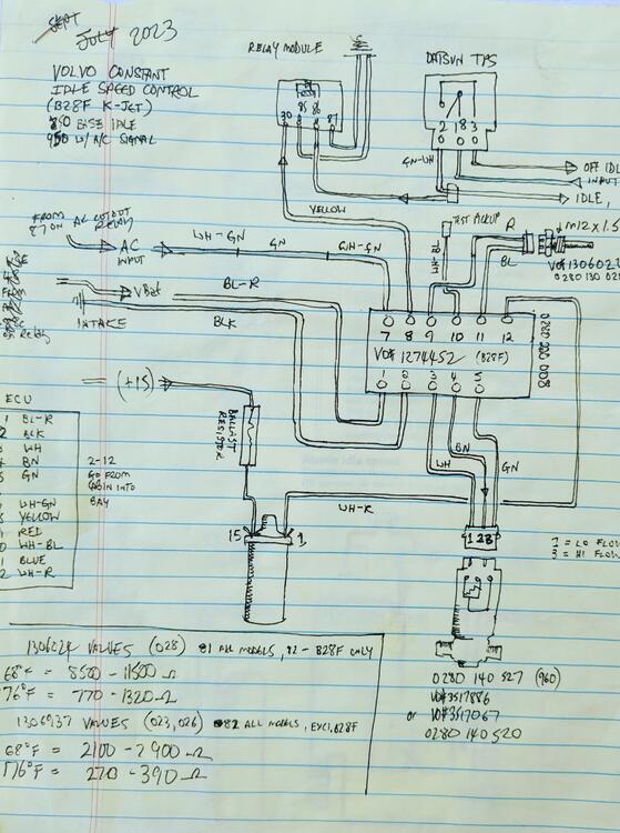
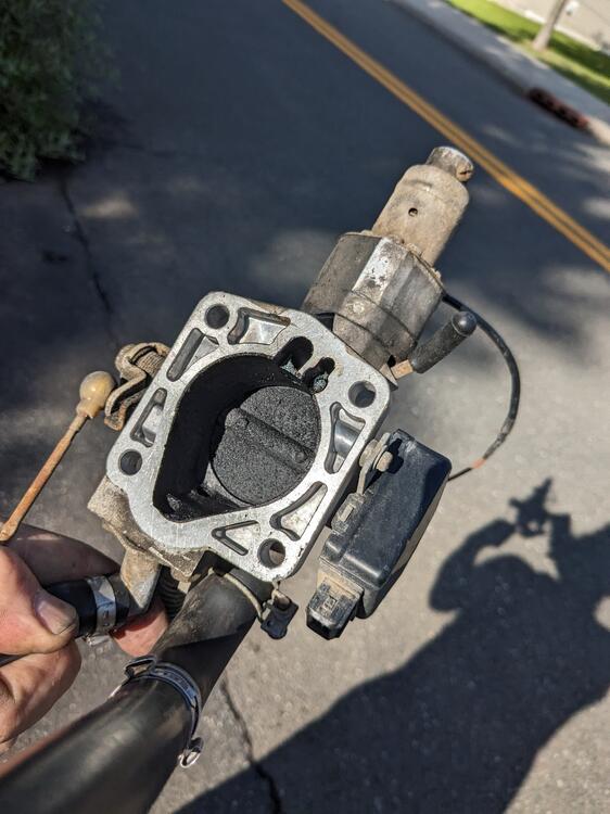
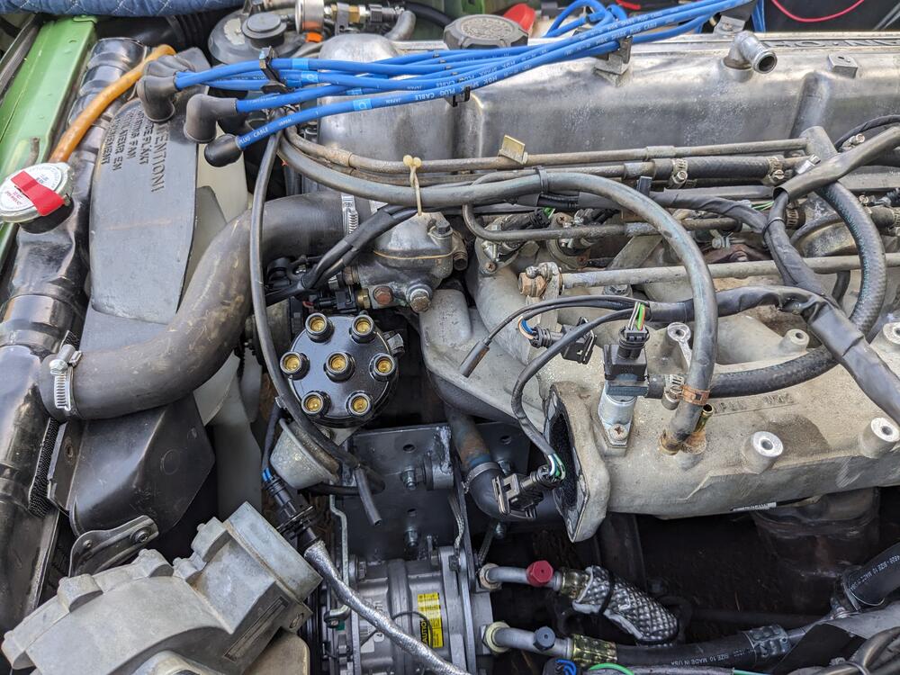
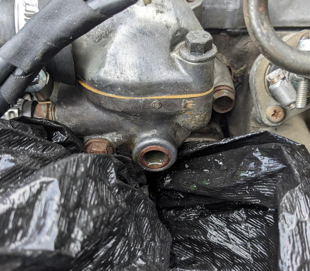
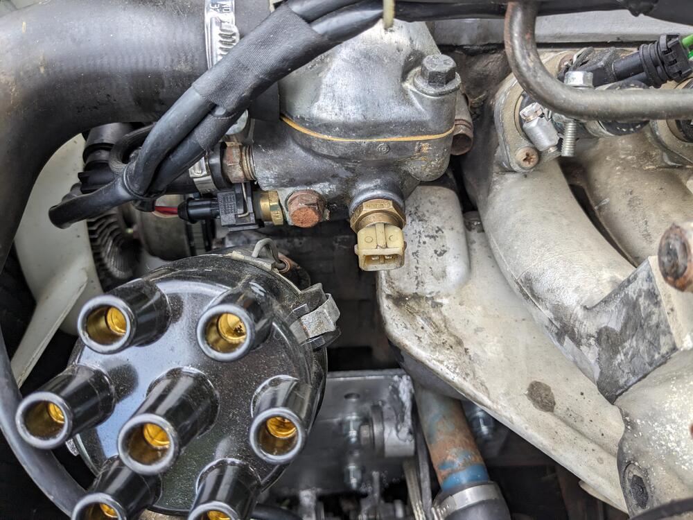
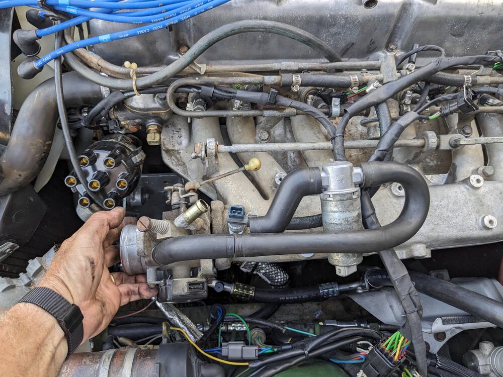
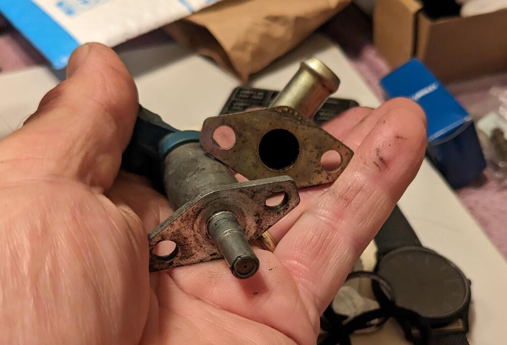
Whilst I've been adding wiring for my AC install, I've also been wiring the Bosch CIS. It was used on Volvos in the mid 80's with K-JET. V6 version - has correct ECU with 6 cyl ignition pulse. (B) Benzine 2.8l (F) Fuel Injection my wiring Bosch 0280 220 008 - Leerlaufregler = Idle Control combined wiring harnesses for AC & CIS module will be tucked up in right corner removed the throttle body. Made it easier to access the water housing to redrill & add a 12x1.5mm Timesert for the ECT Lots of grease on the drill & tap, picks up the shavings ECT 0280 130 028 (VO 1306024) installed IACV will go something like this. CSV will move to throttle body, where air port is now. CSV port will be used for the IACV return Flange offset/bolt spacing is identical. Edit - Volvo uses an o-ring for the CSV - have to check the port ID in the TB
-
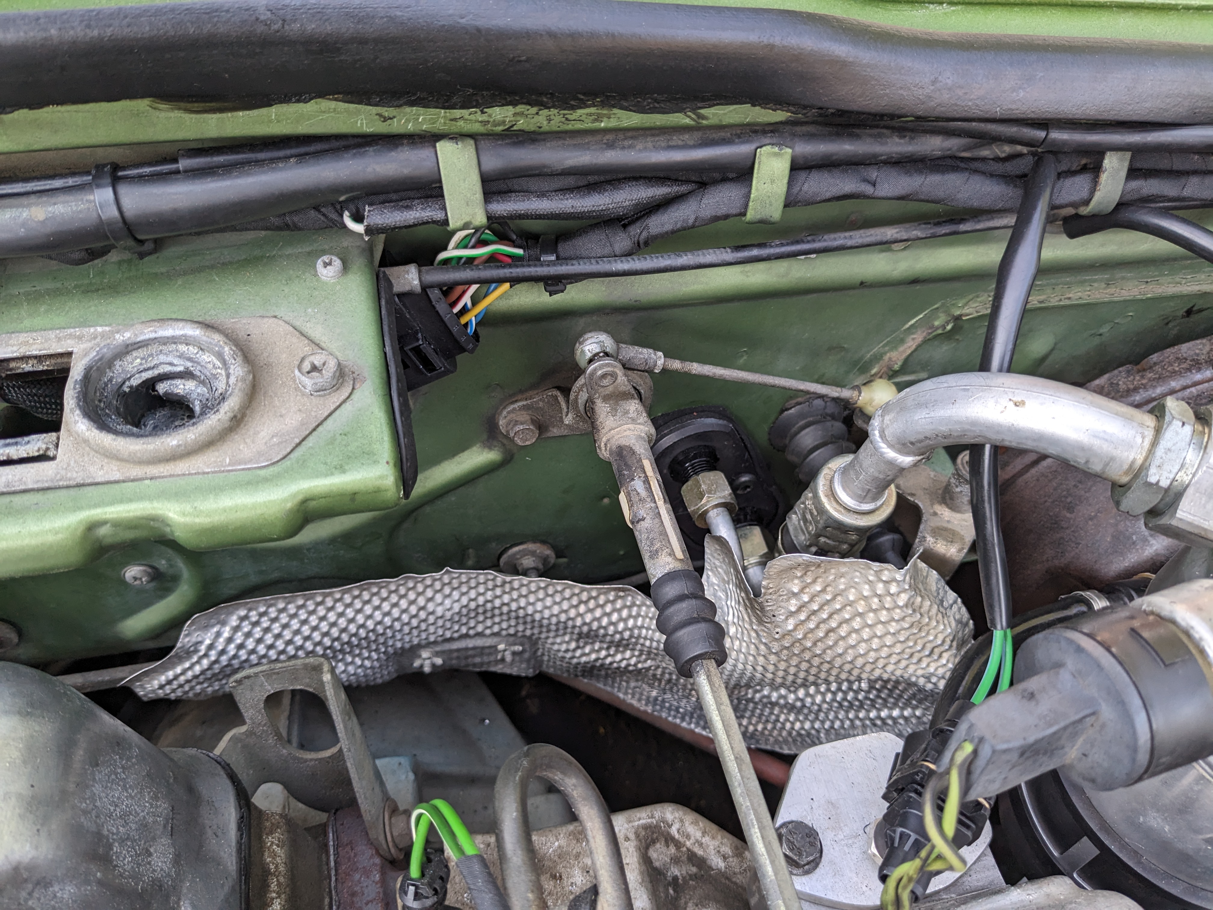
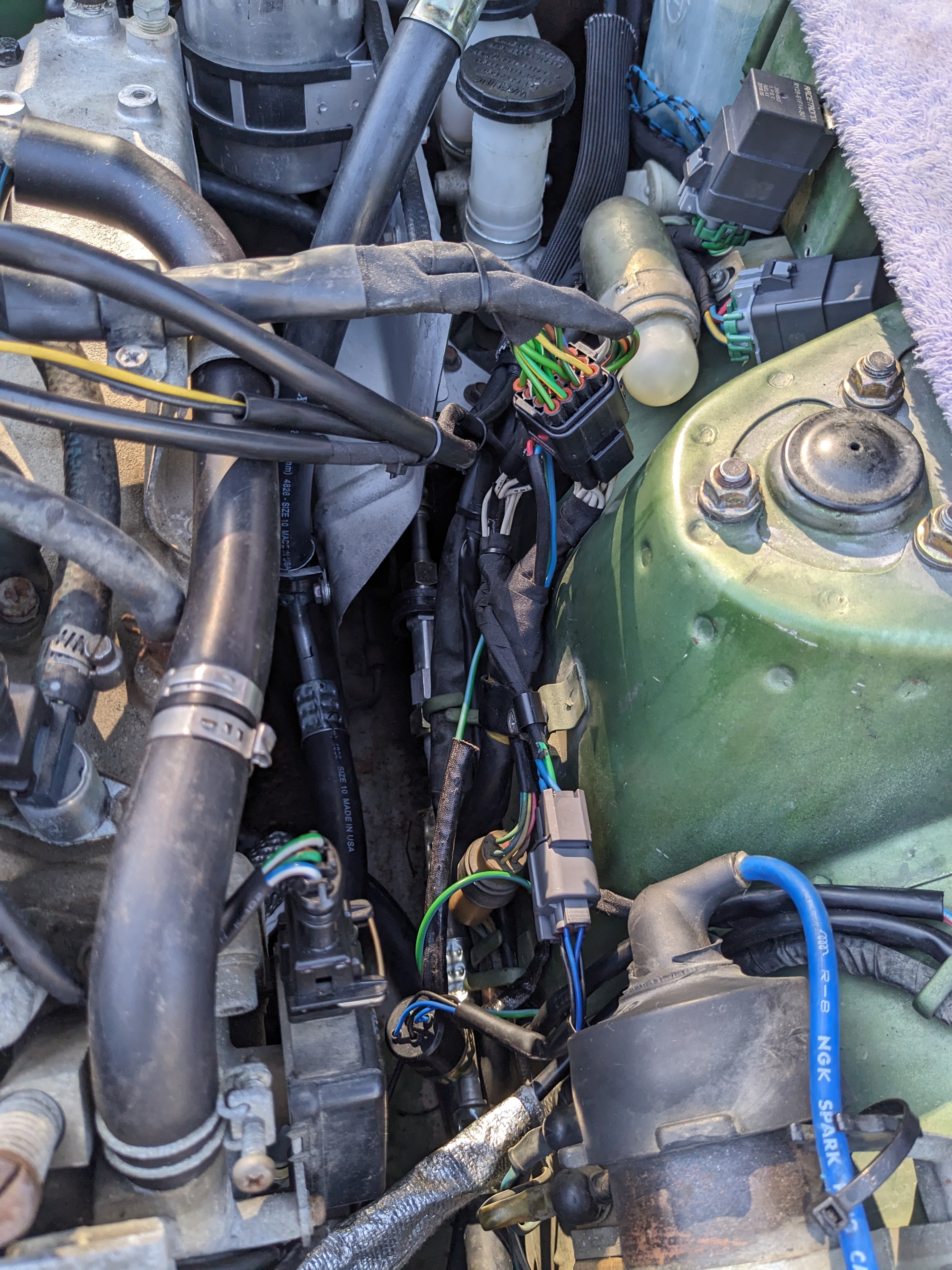
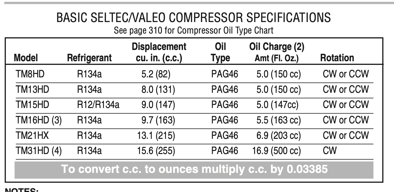
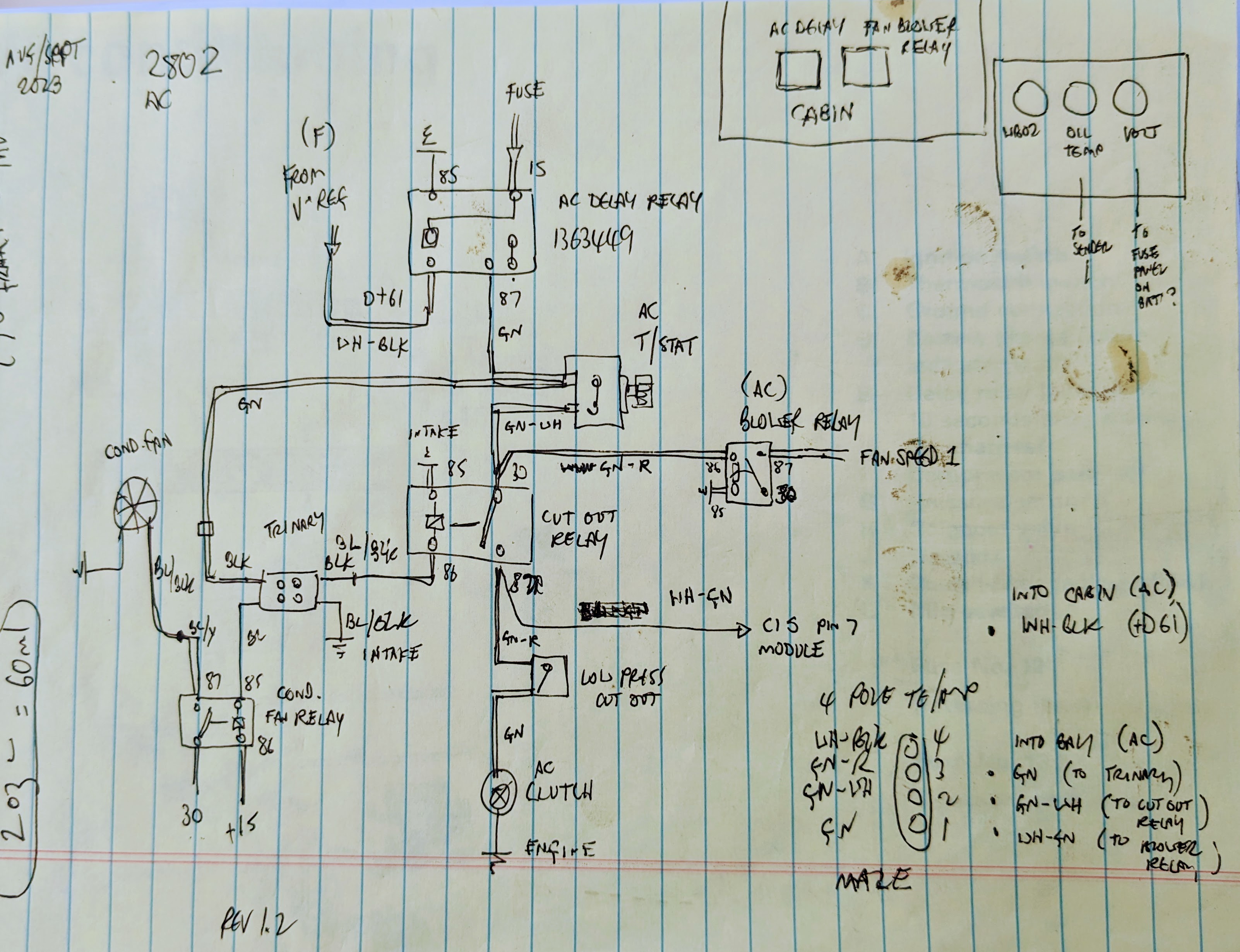
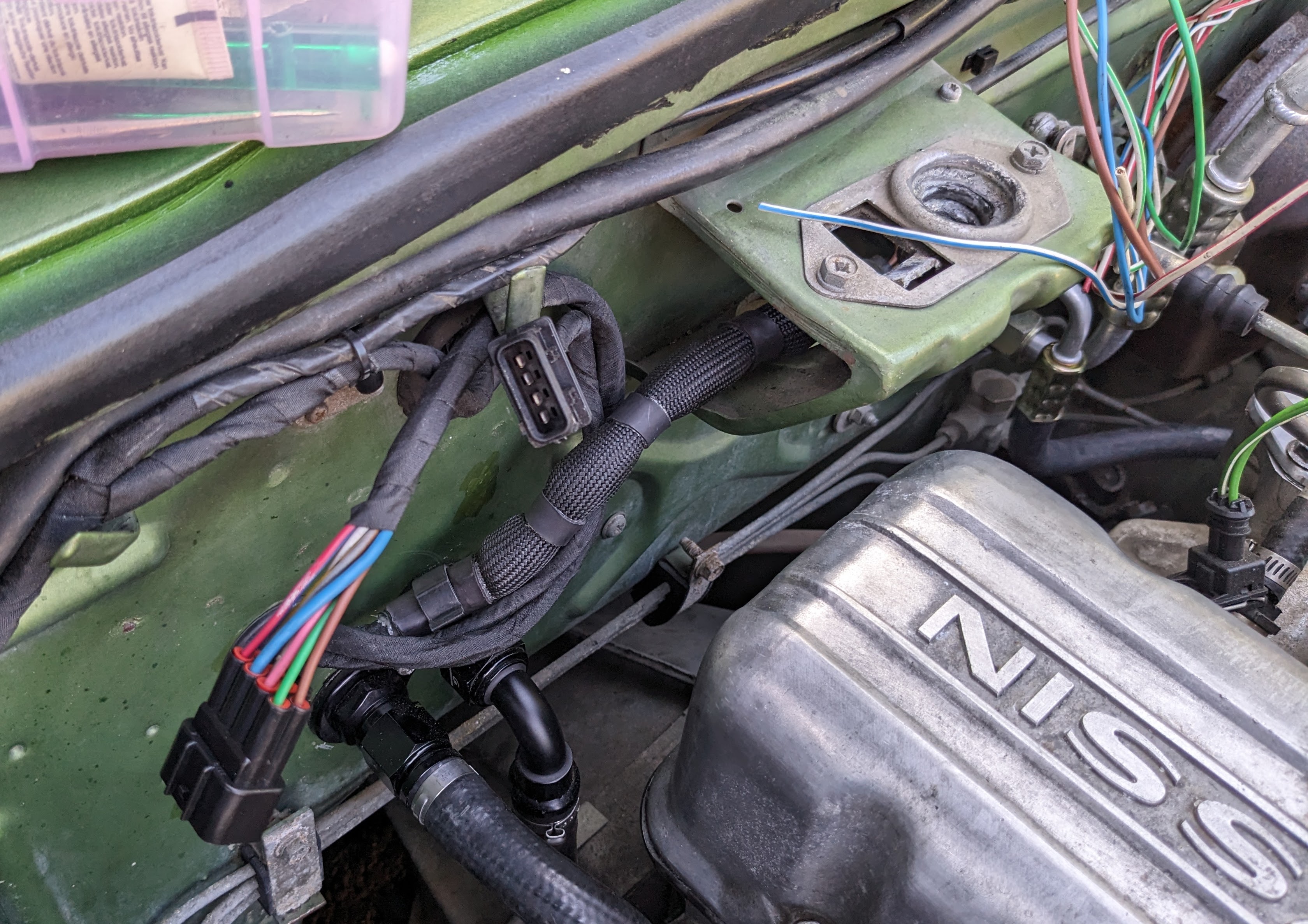
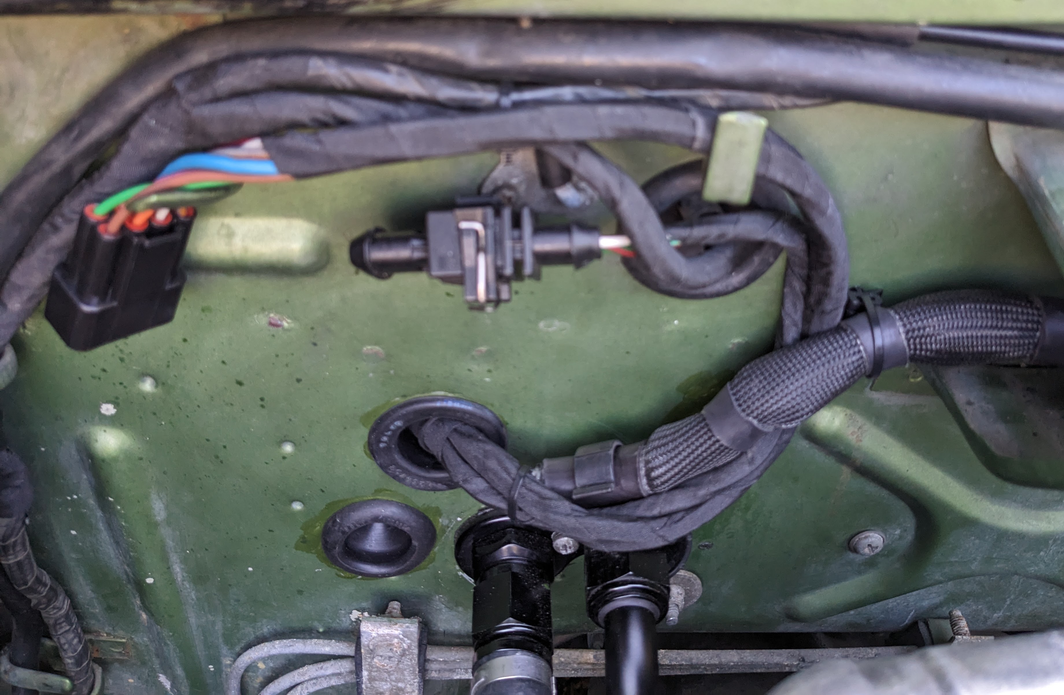
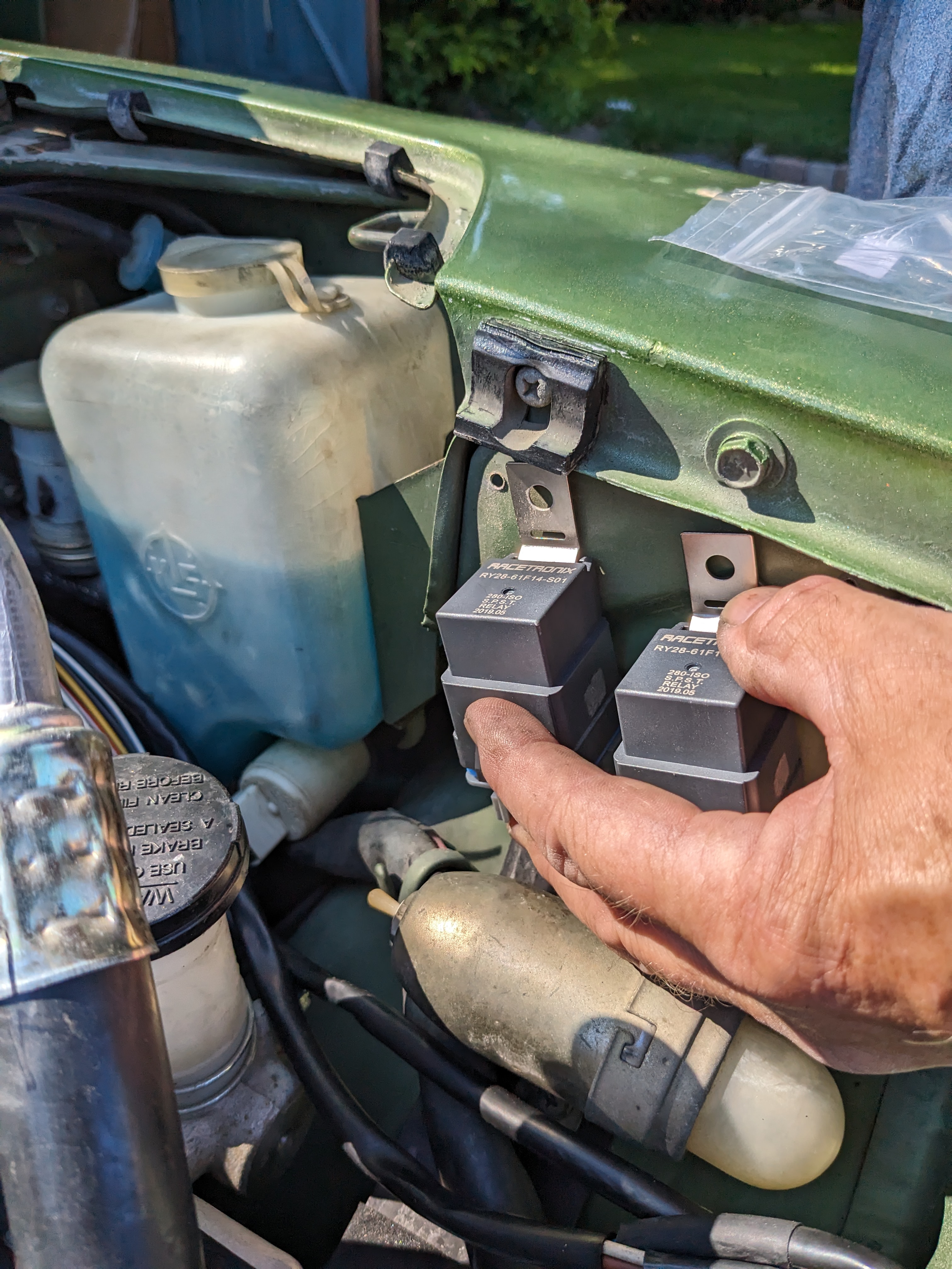
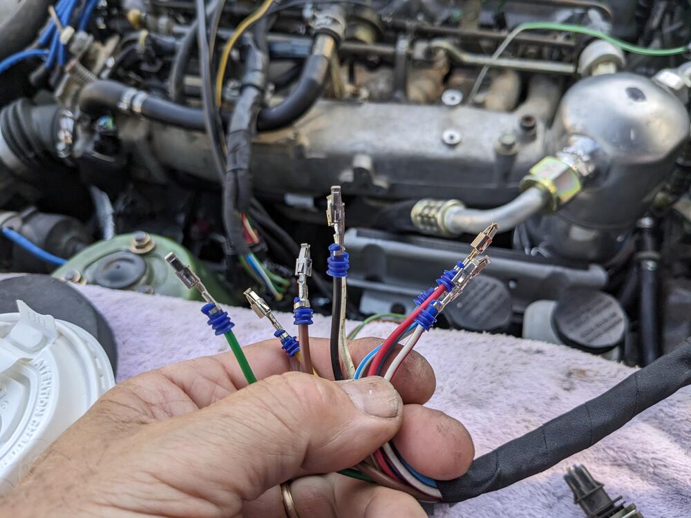
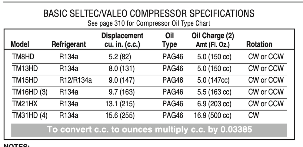
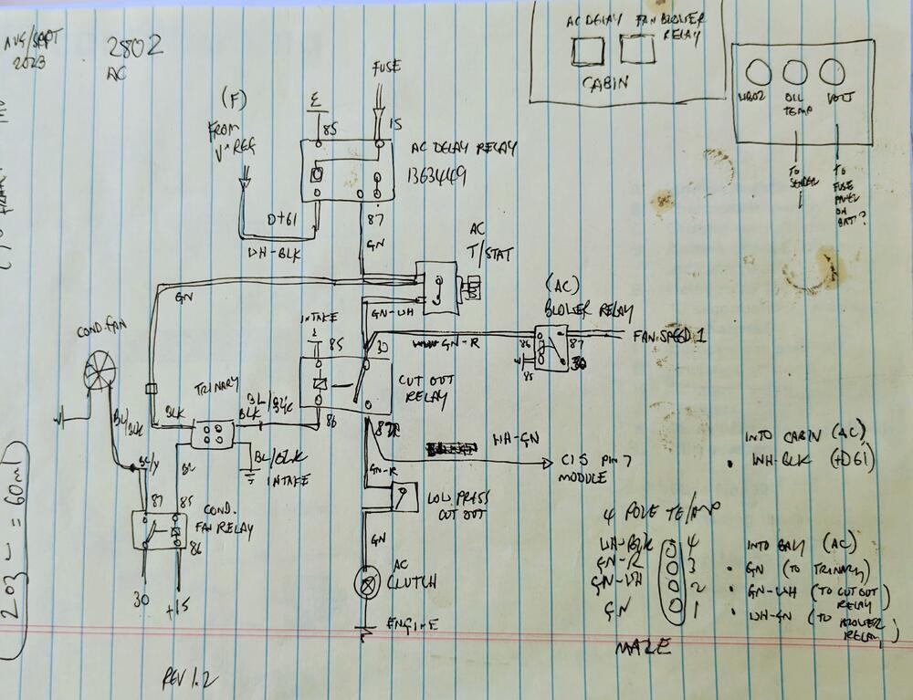
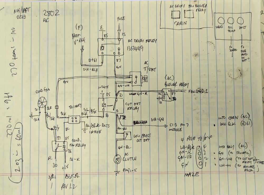
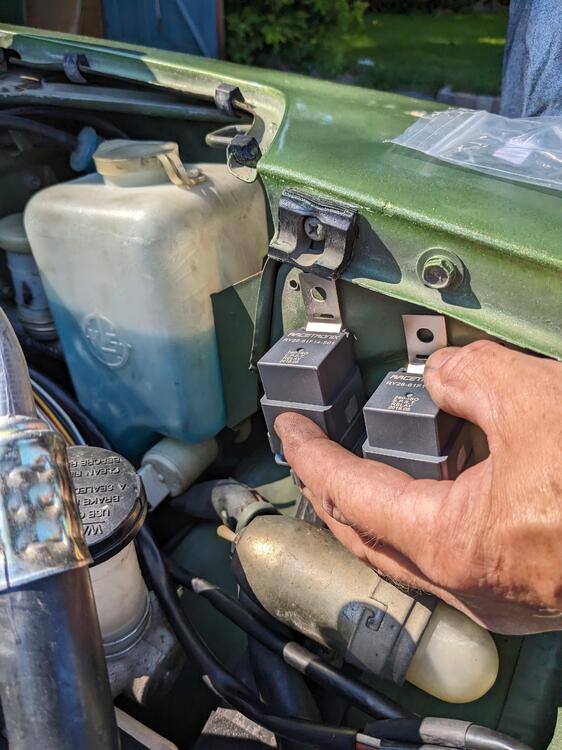
More wiring. Realized I have to remove the compressor as I didn't drain the mineral oil - I forgot that this compressor (TM15D) was setup for R12. Have to refill with Pag46 wiring overview Tucked behind hood catch, secured to firewall to make sure no issues with throttle linkage. Low pressure cutout on accumulator in foreground Harnesses routed alongside stock wiring. Have to secure the 2 relays
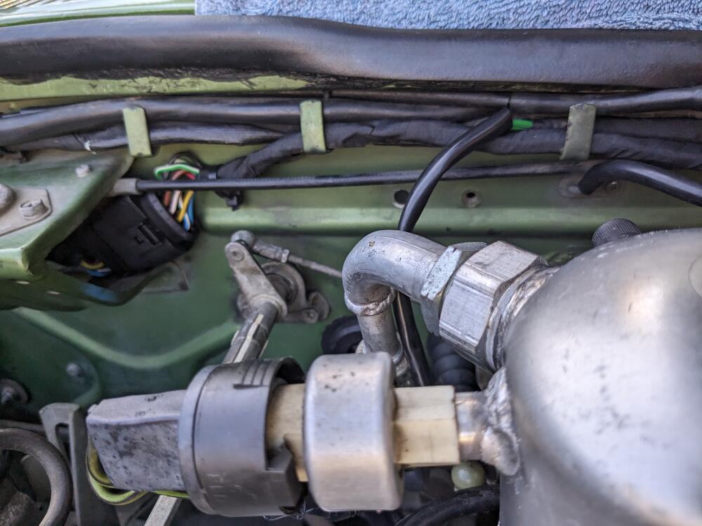
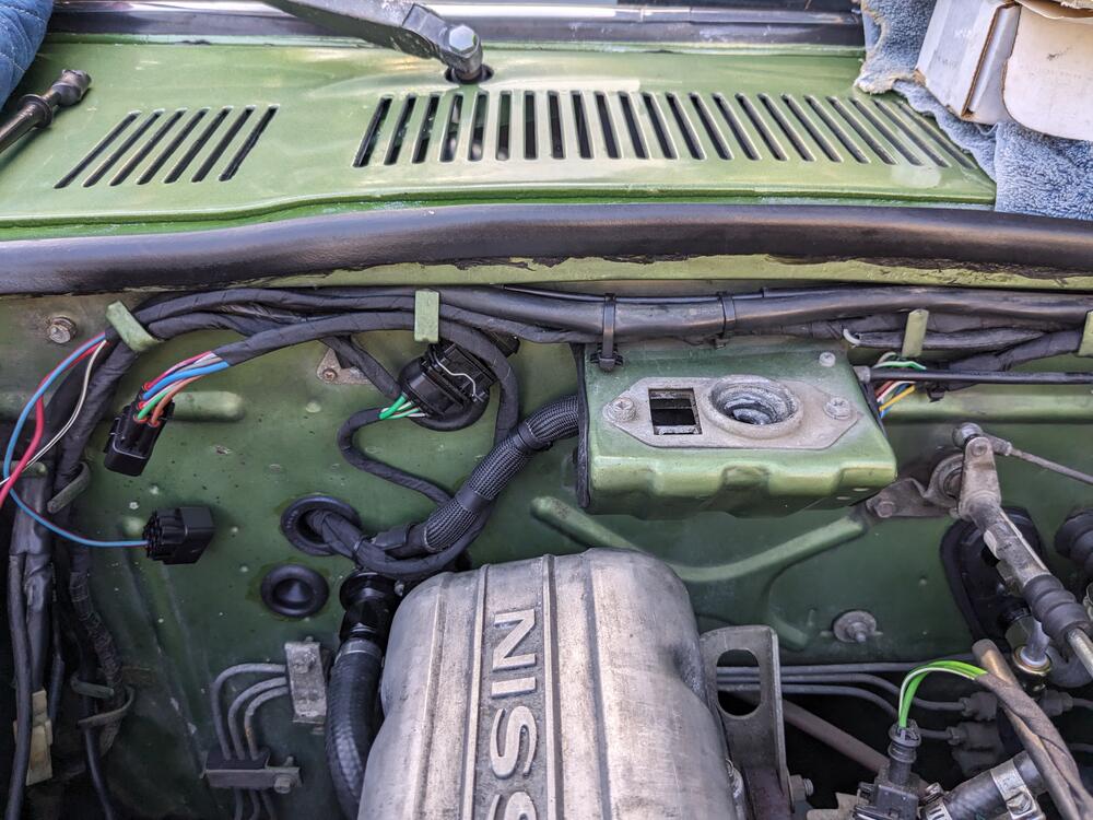
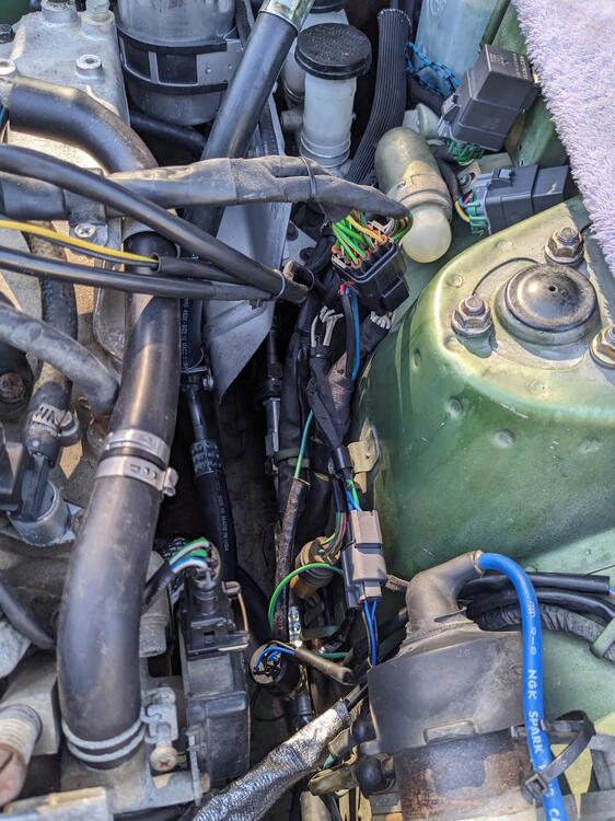
-
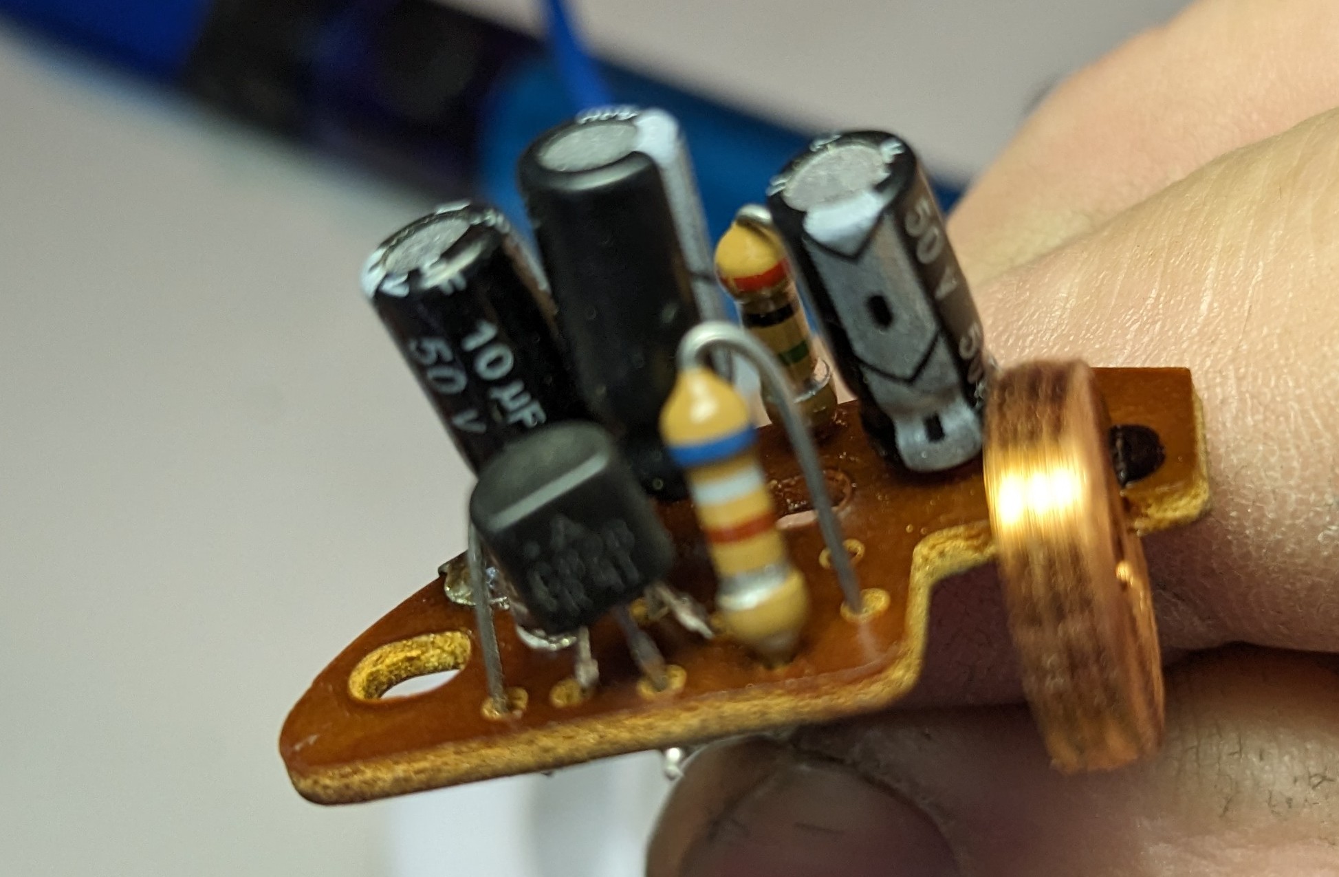
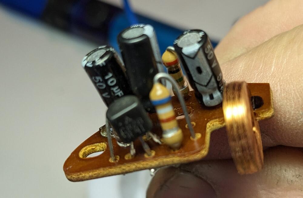
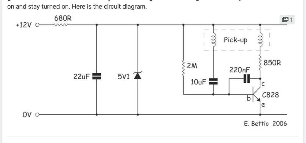
Ah - so I assume I need to alter the post to board configuration (swap b & c?), since I bought 2N3904 transistors. My 75 is CA market - so if you need any of the 75 smog-specific components I may be able to help 🙂 I'll check the coil values also.
-
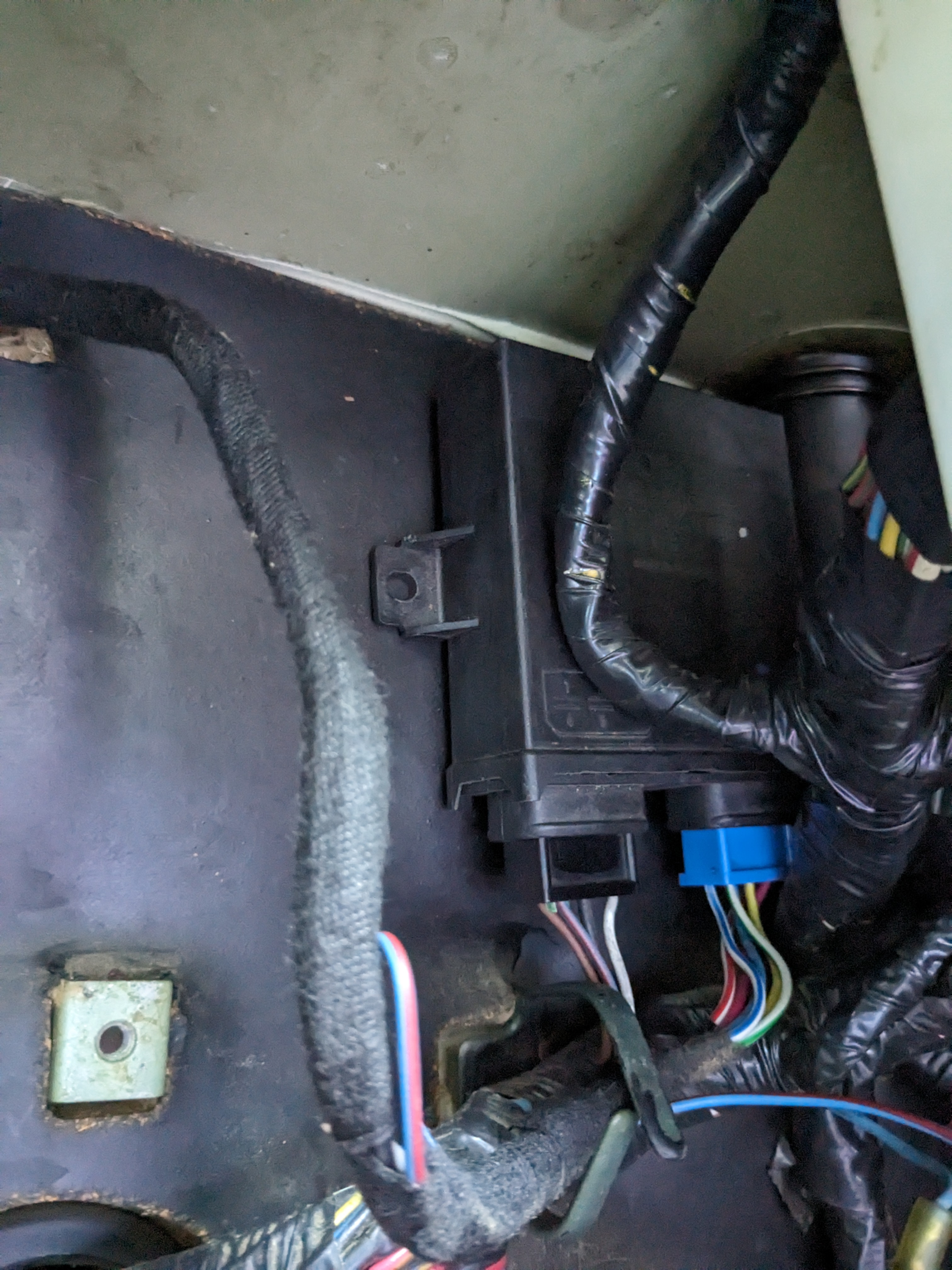
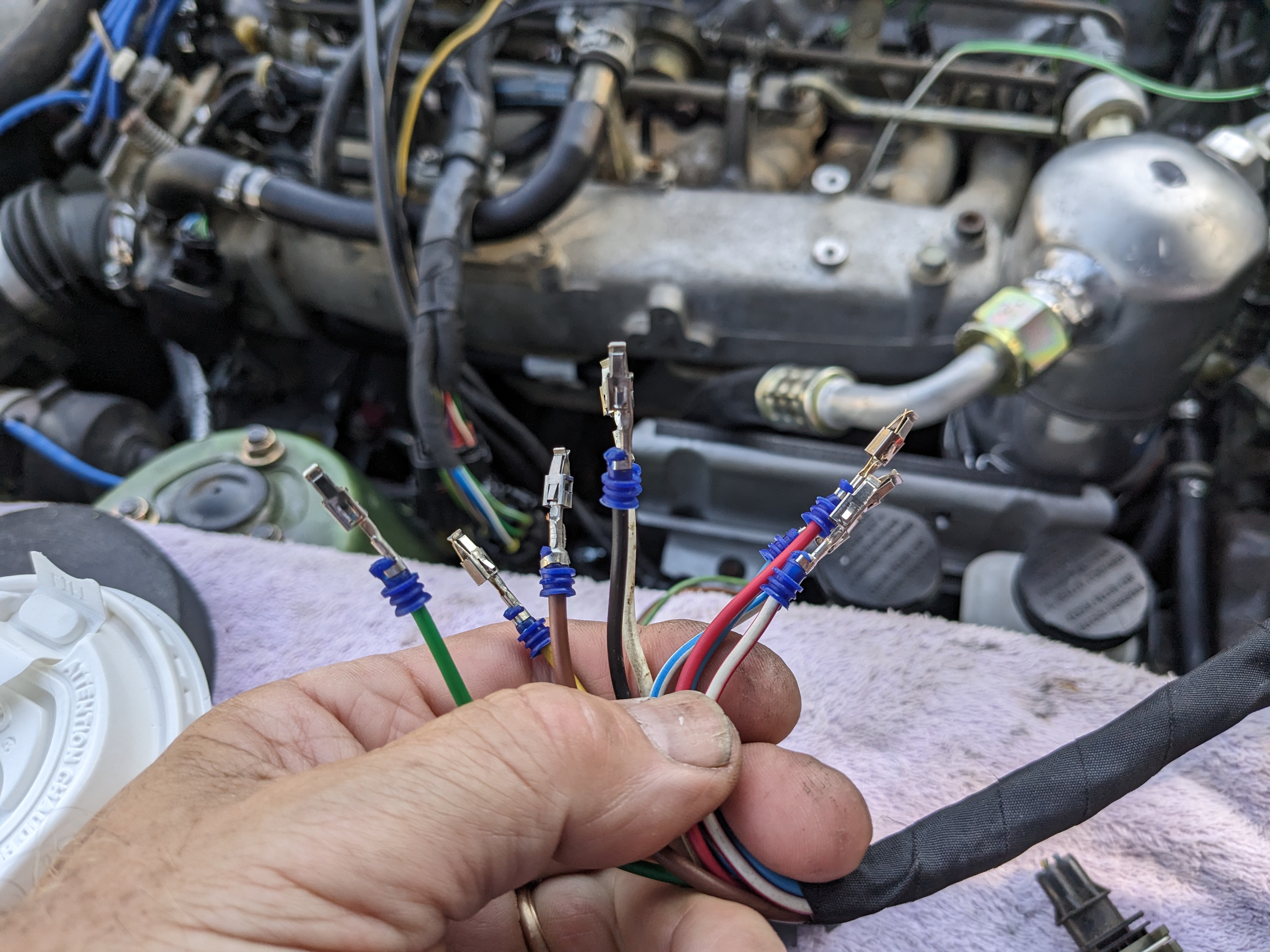
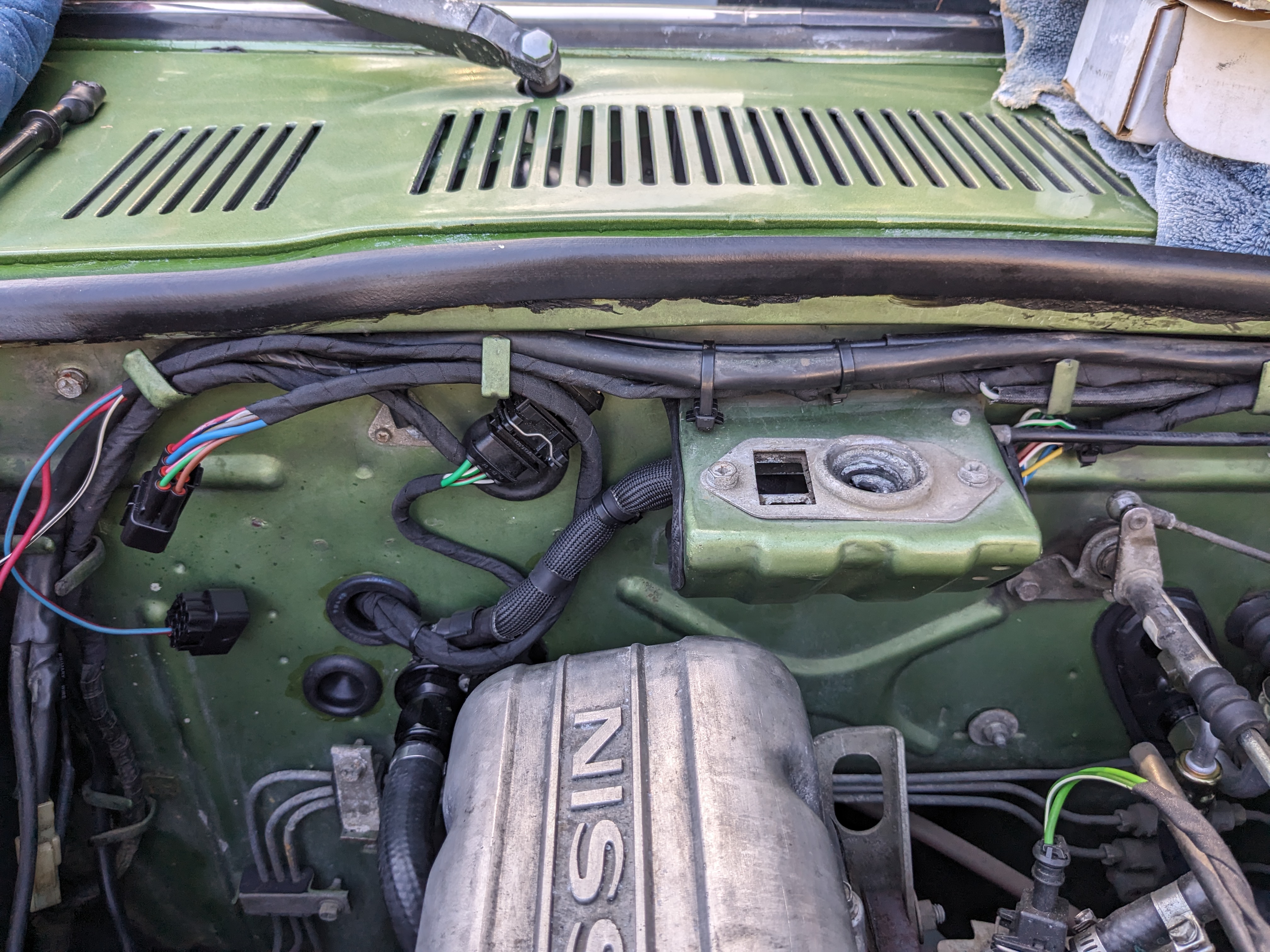
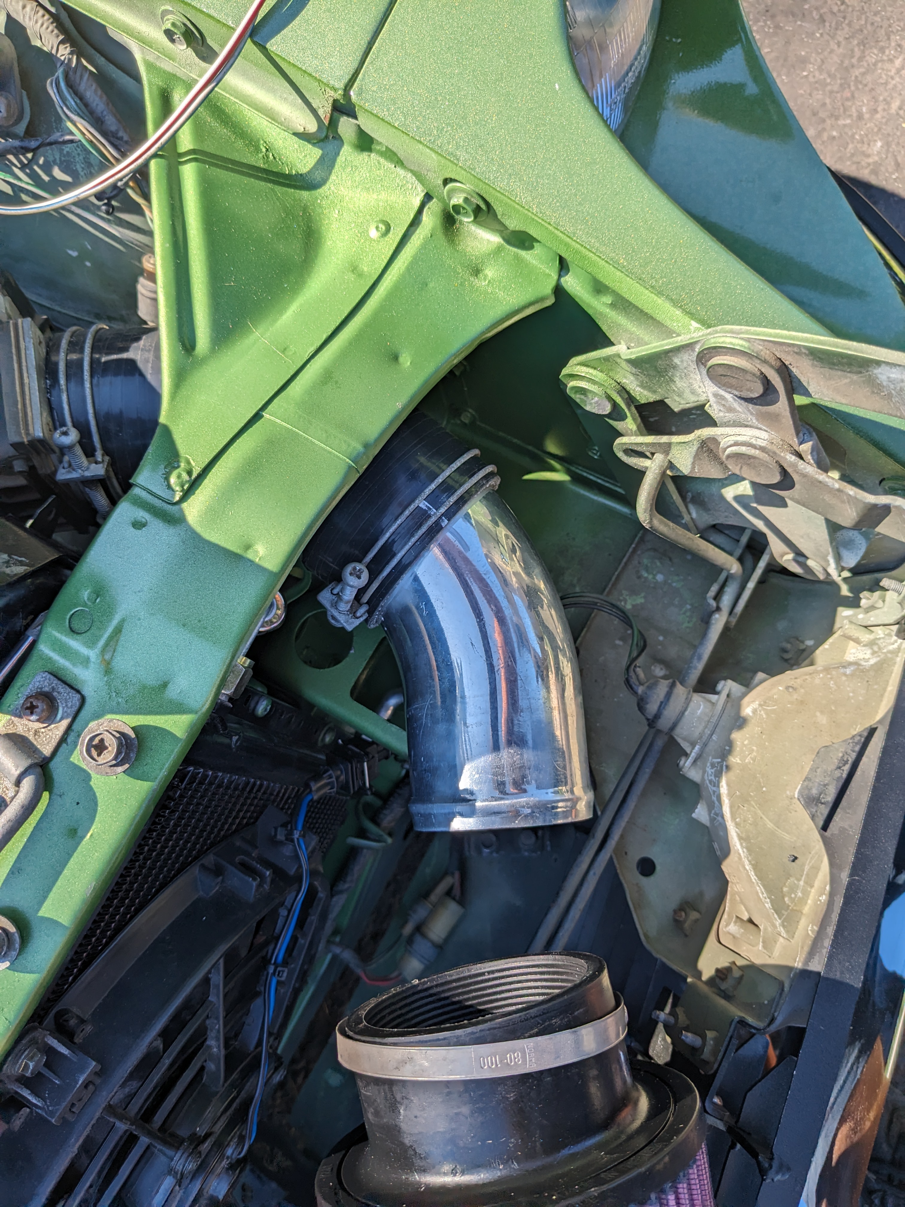
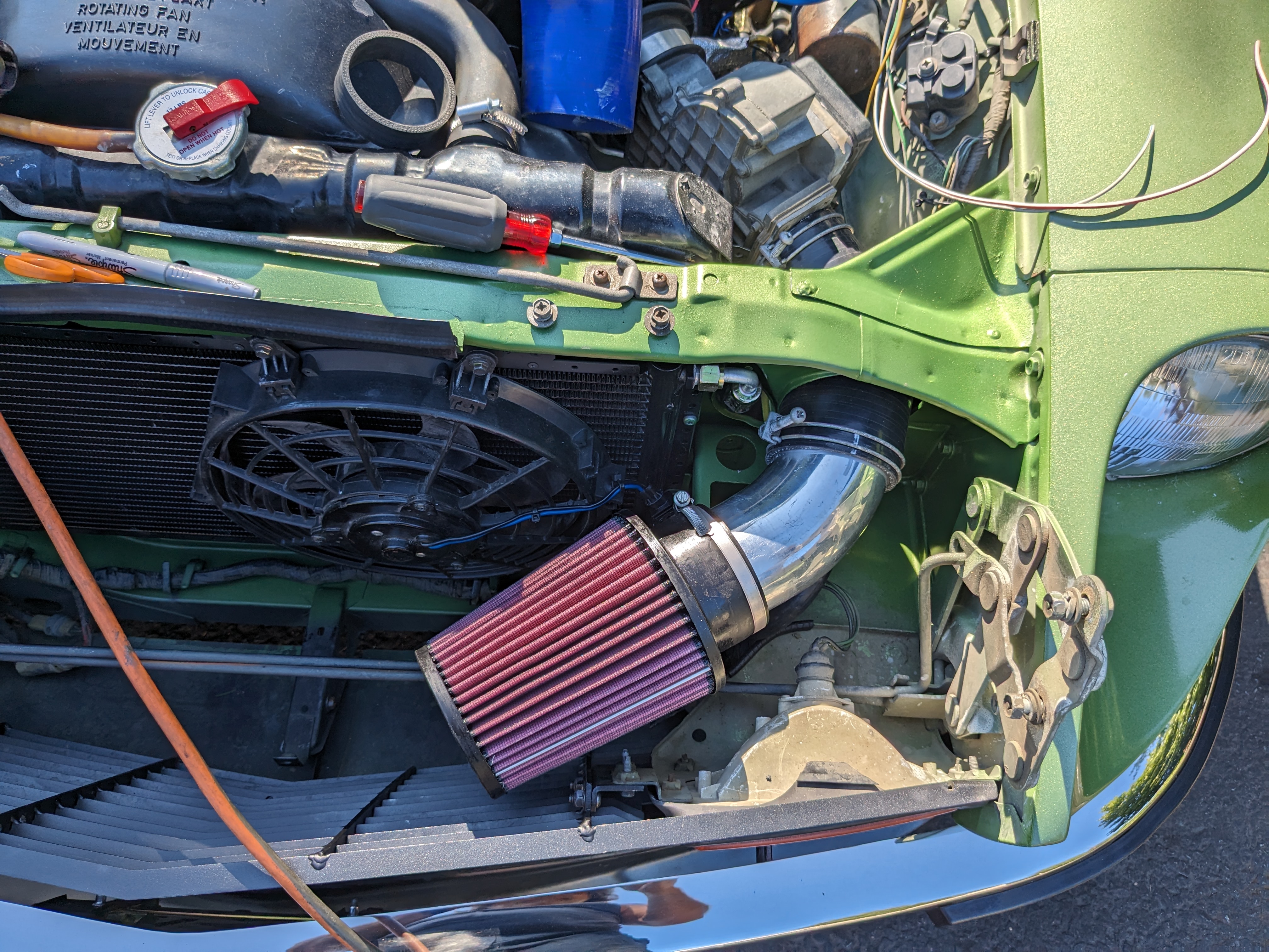
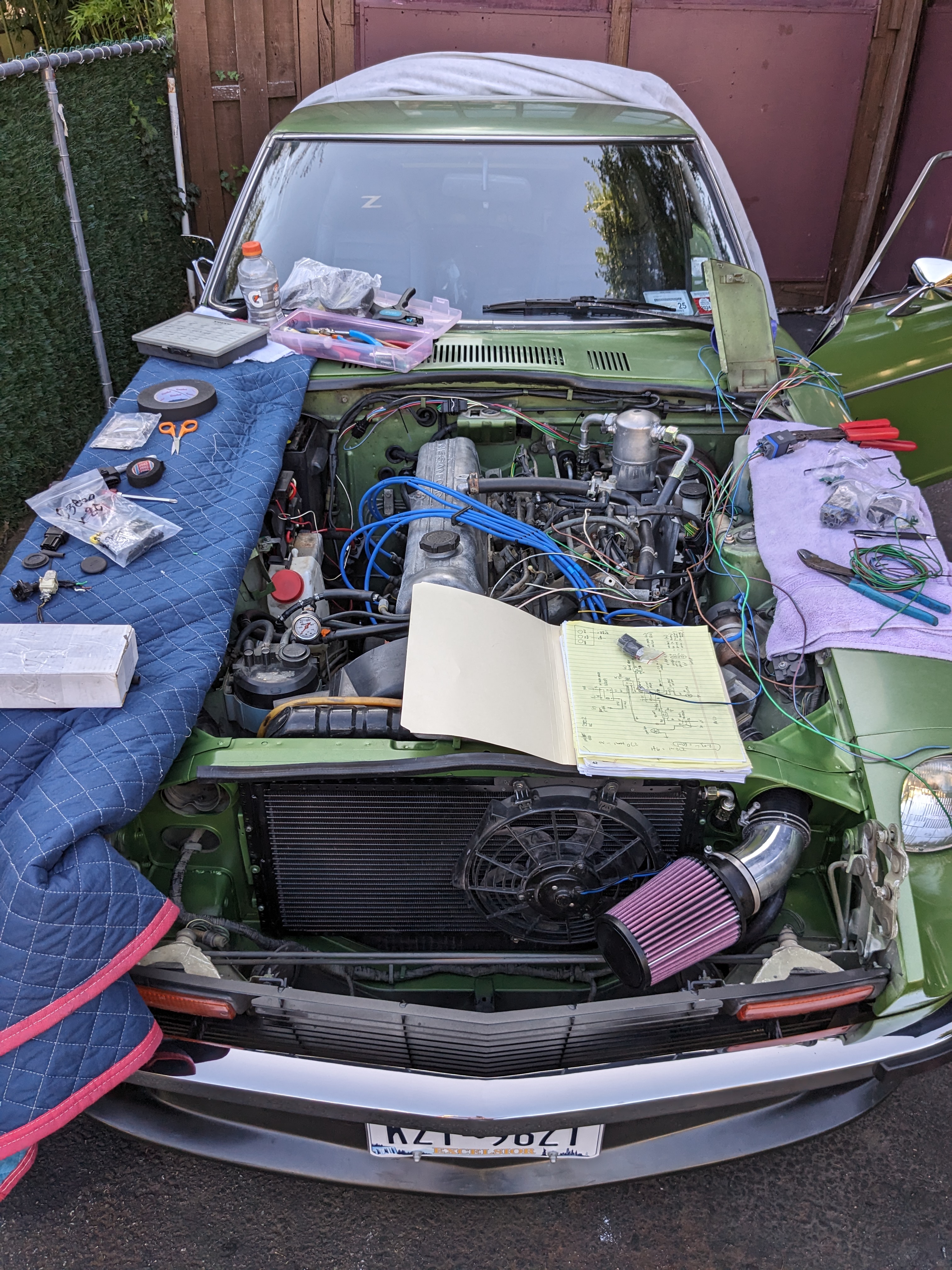
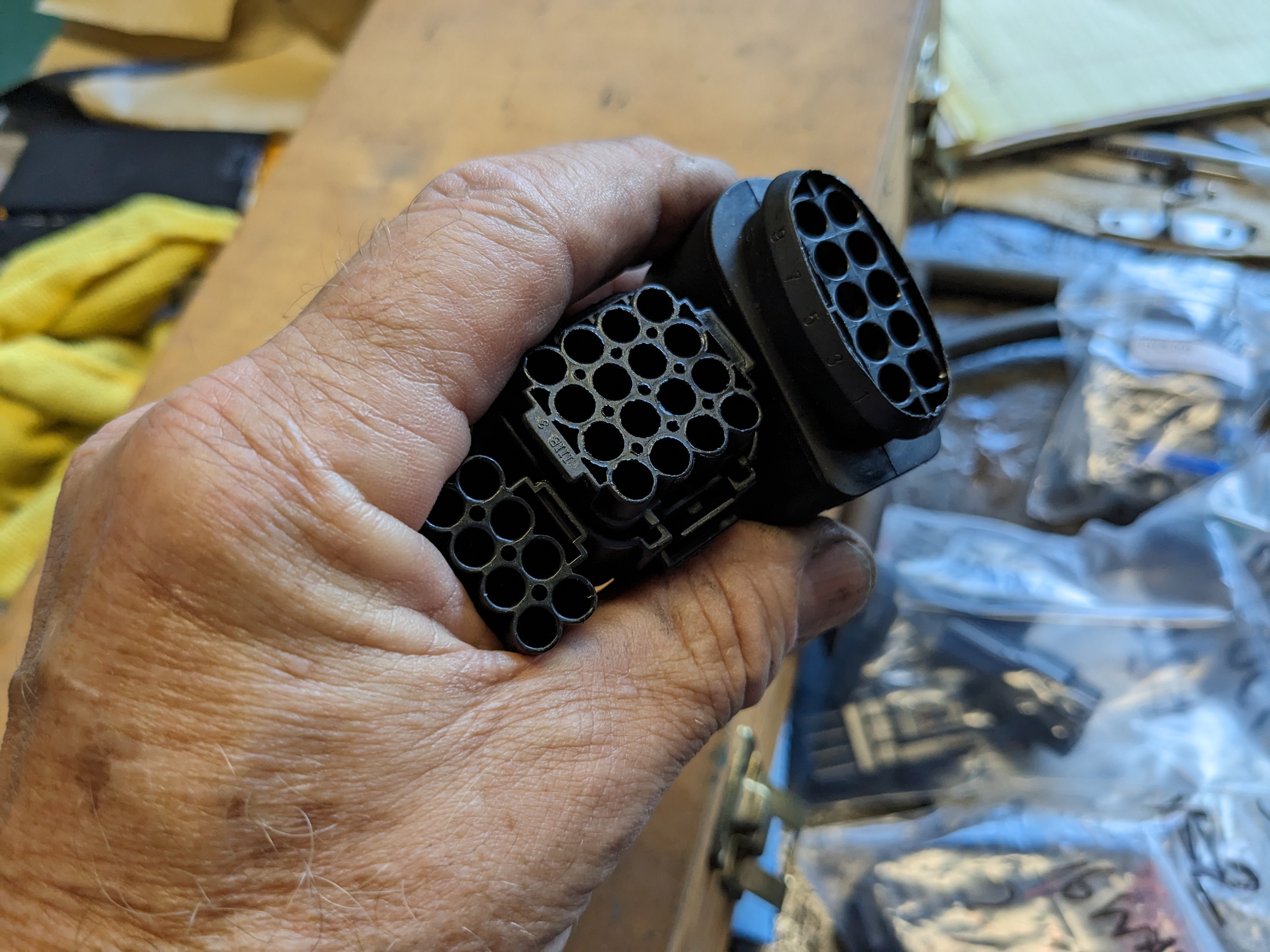
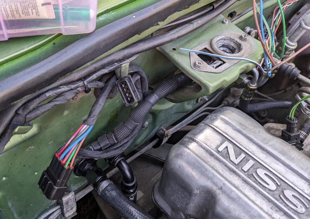
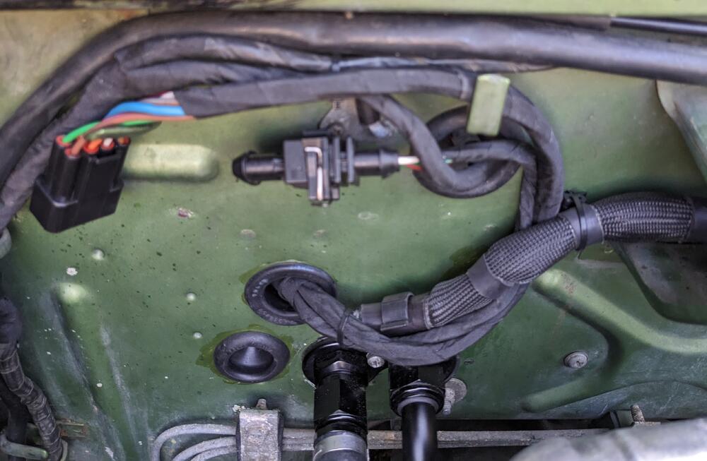
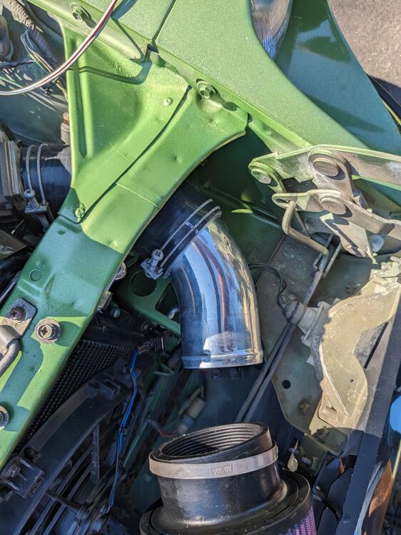
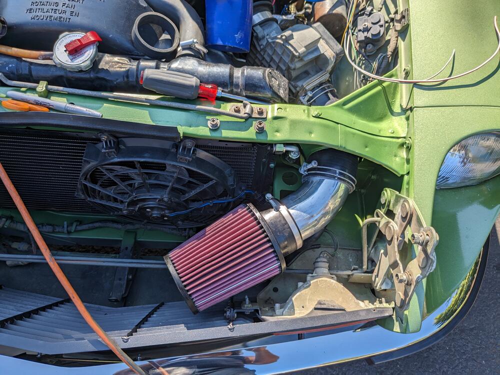
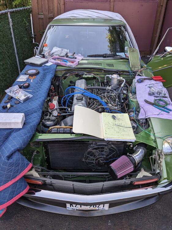
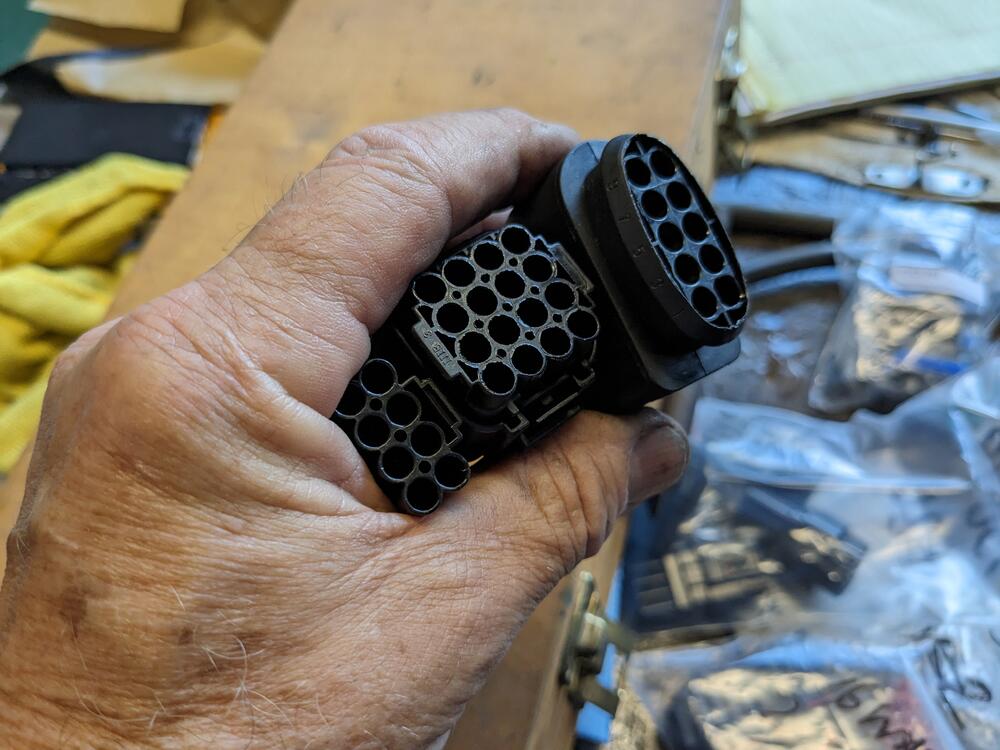
After I worked on the clock this morning, I worked on the AC wiring harness today, in conjunction with the harness needed for the Bosch Constant Idle Speed (CIS) system 2 10 pole connectors (one tucked under the hood catch, for CIS) & one 4 pole. The 4 pole covers the AC control signals. AC cutoff & AC cond. fan relays will go here. The details on the ID tag weren't legible anyway wiring inside. Made sure it doesn't interfere with the heater fan box CIS module will go up here K&N (RU-4650) filter arrived, so I put that in. Required since the AC condenser fan interferes with the stock airbox fitment. I have a plethora of 2.75" & 3" silicone couplers & aluminum pipes from various Volvo projects, so I used a 2.75" - 3" elbow coupler & 3" bend to fit the 3" inlet filter. Made sure the filter surface area far exceeds the demands of the engine displacement at redline (calculator for that) hopefully wrap up the bay side of the wiring tomorrow.
-
It doesn't stay running. If I push start the wheel it doesn't continue to run if powered, I don't think there is any difference in spin duration powered or unpowered.
-
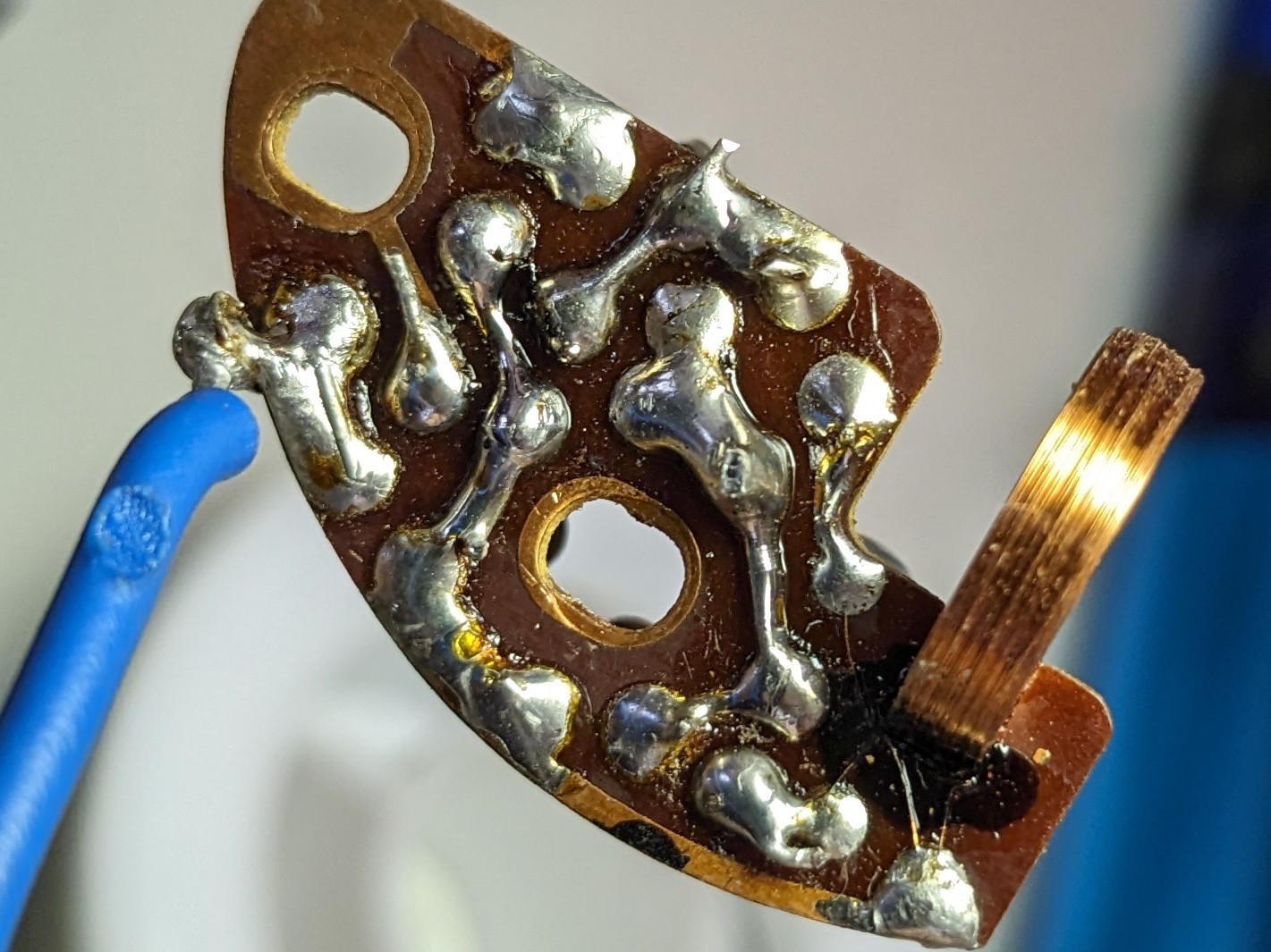
Hello Ron Thank you for the advice. I've done the 3 caps, and after that I got a twitch from the balance wheel. so I will see if I have an NPN transistor to try. I missed refurb boards on your site, so if this doesn't work, I will be hitting you up for a board. I want to keep this clock if possible.
-
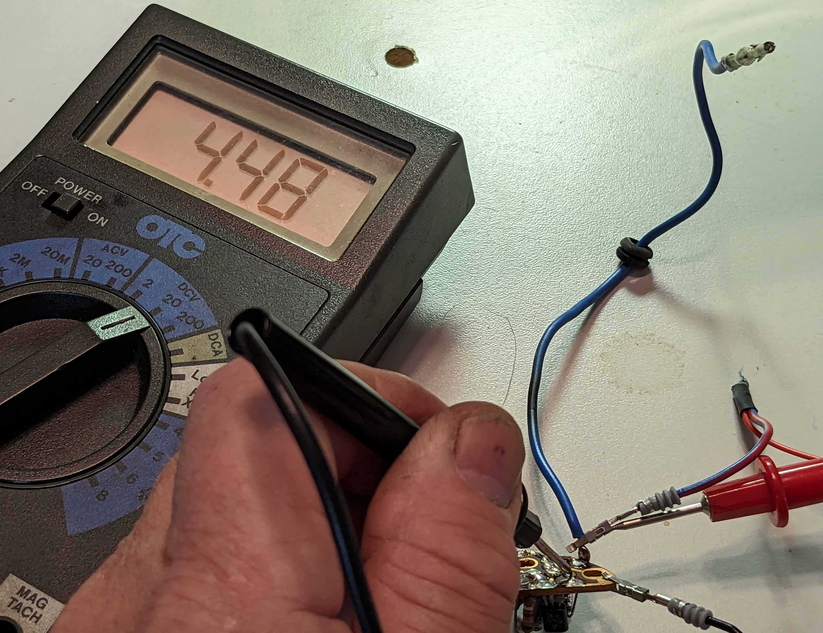
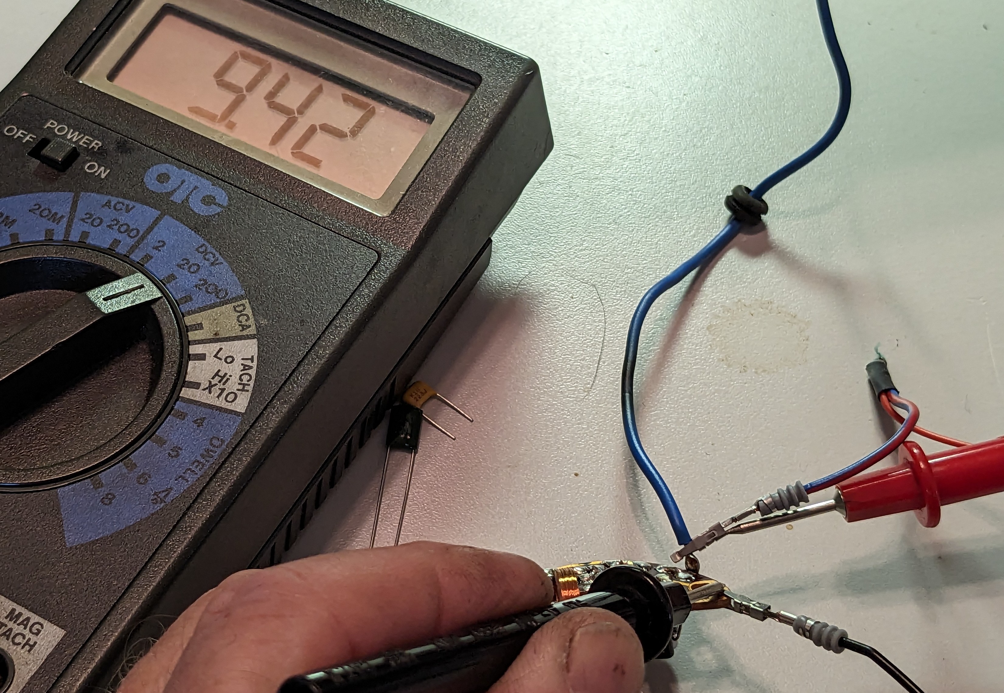
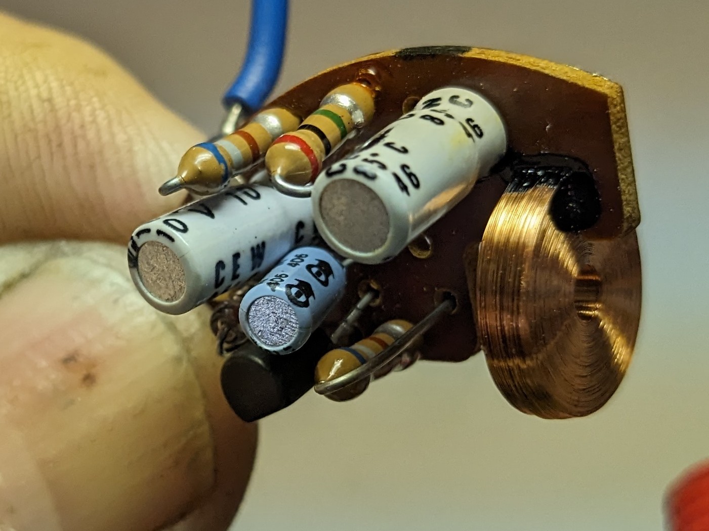
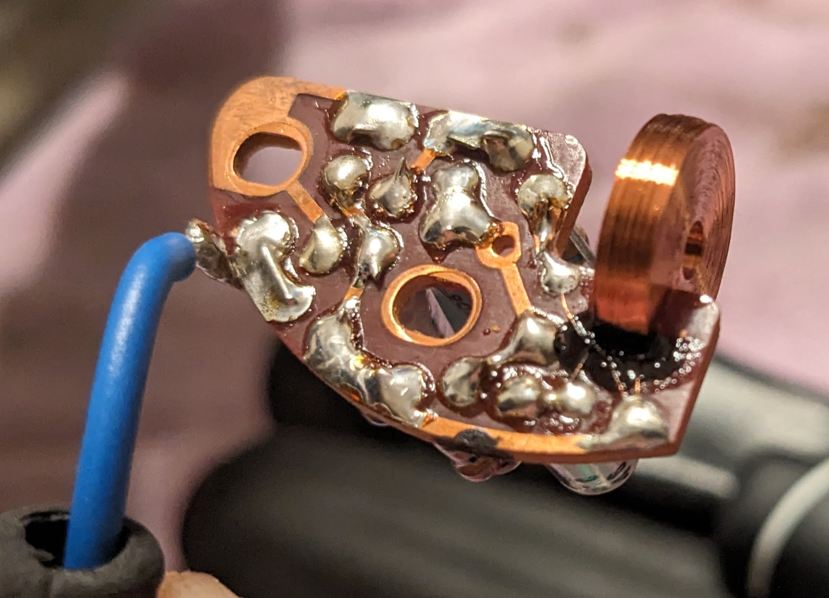
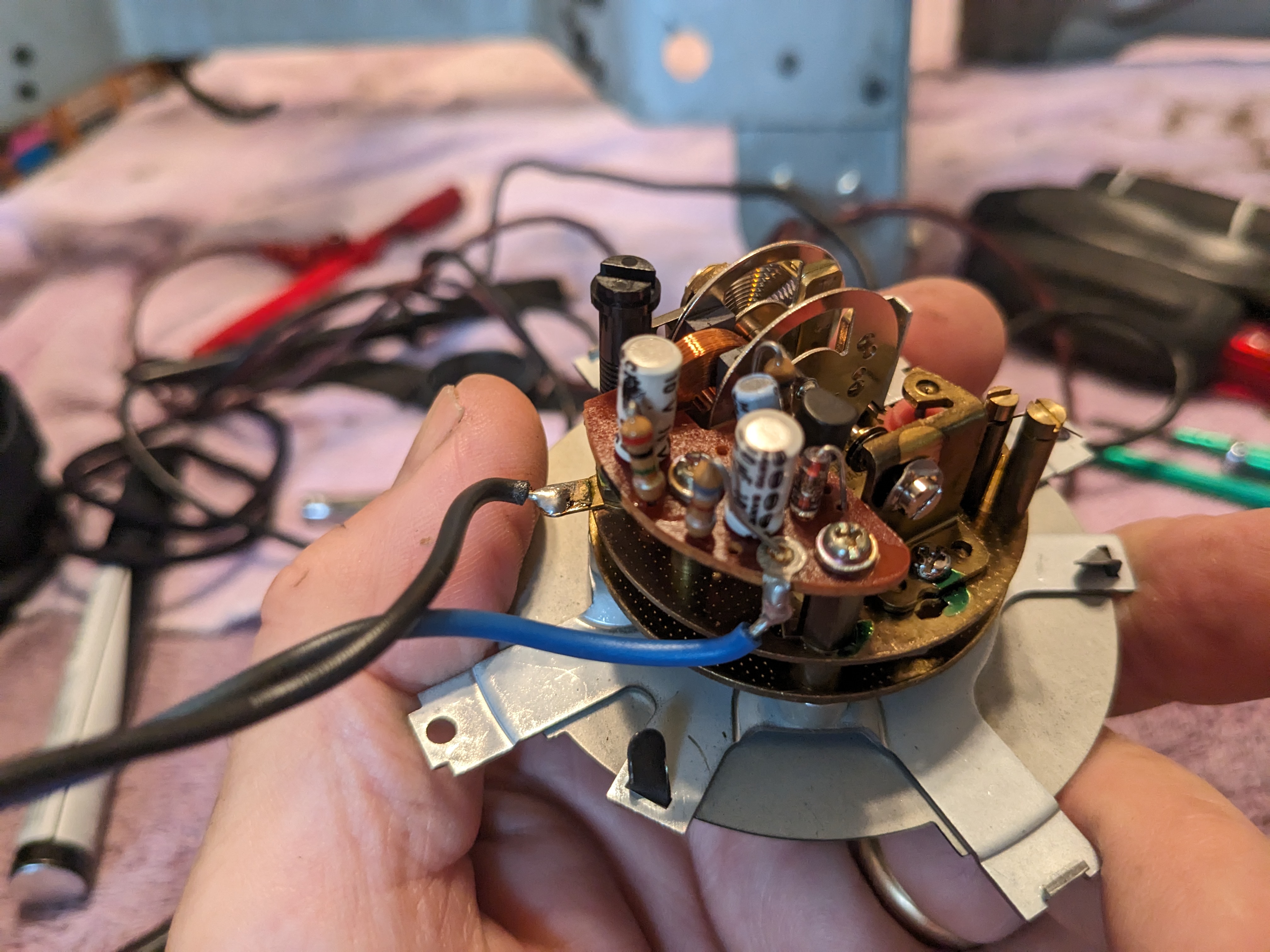
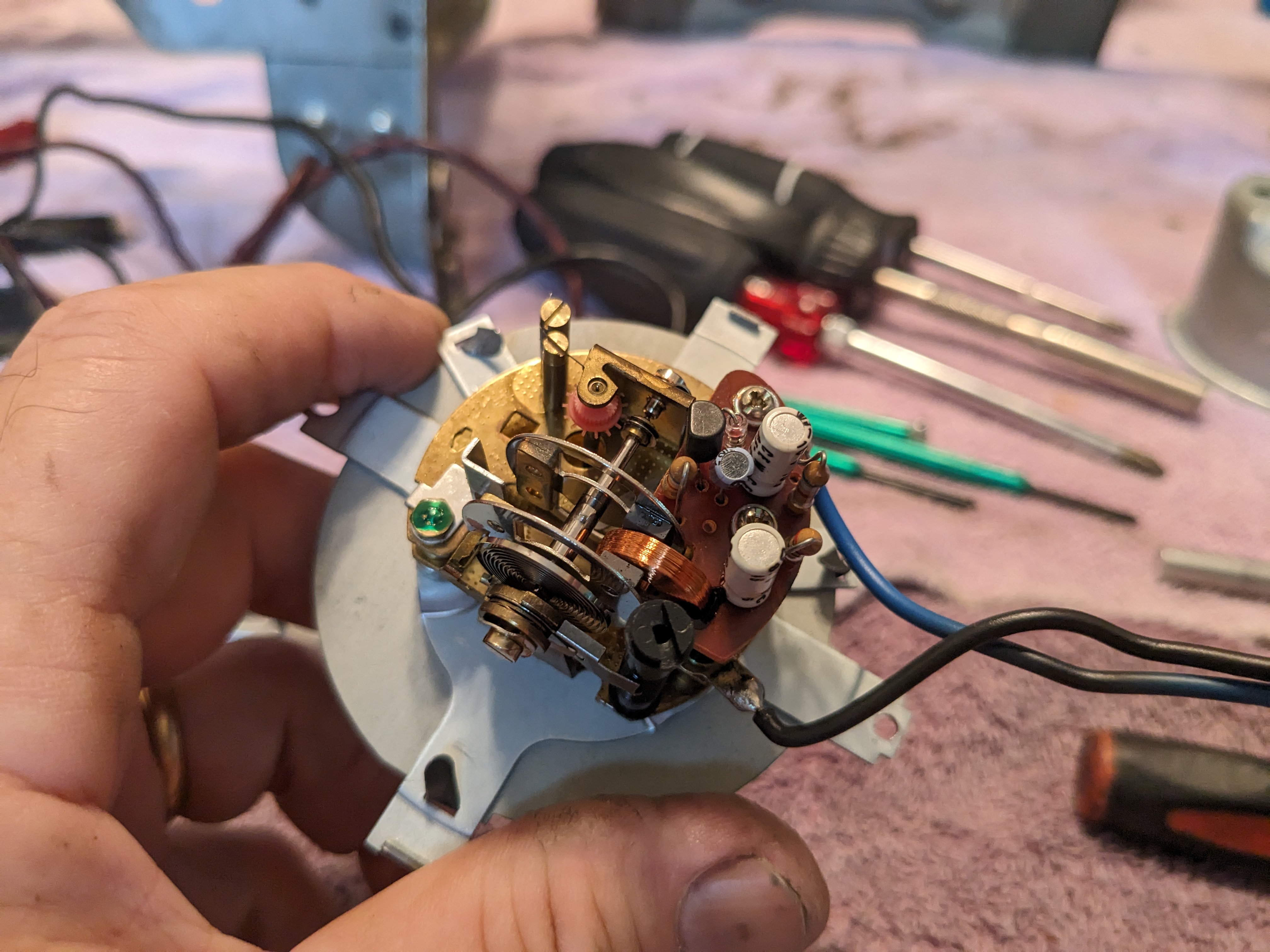
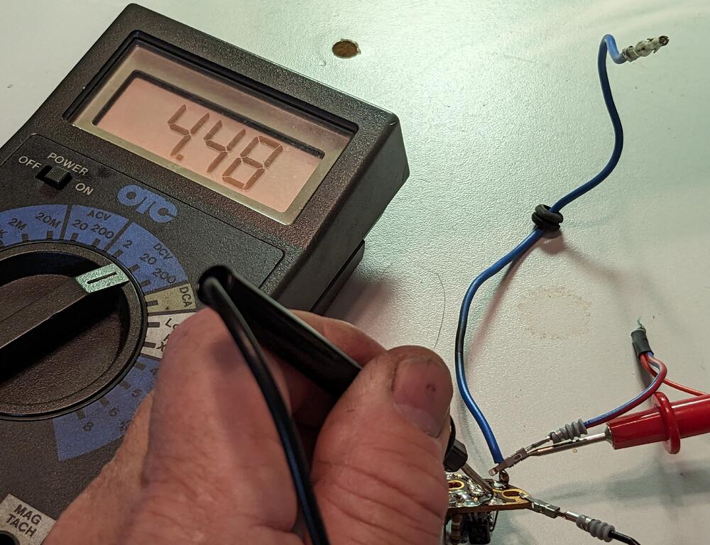
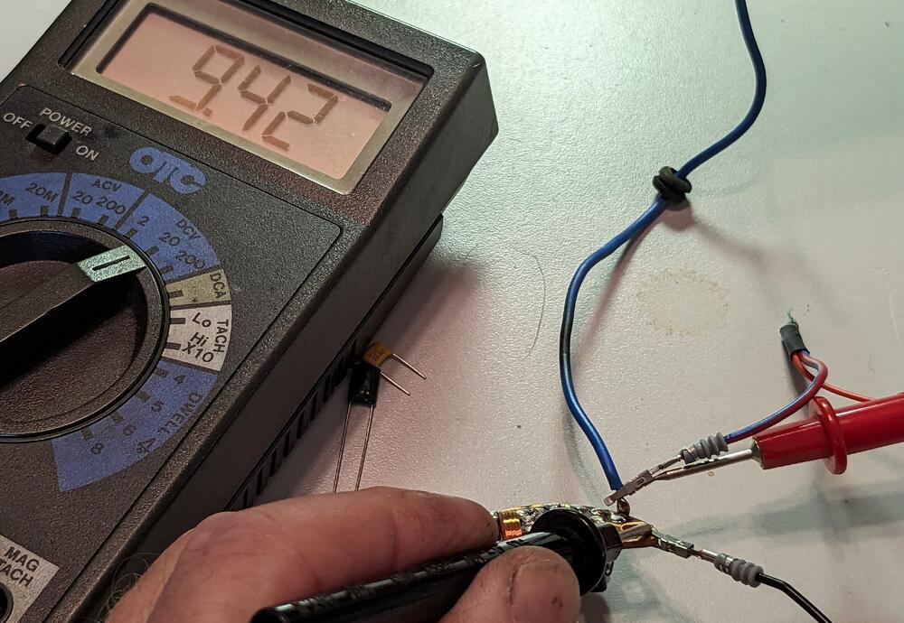
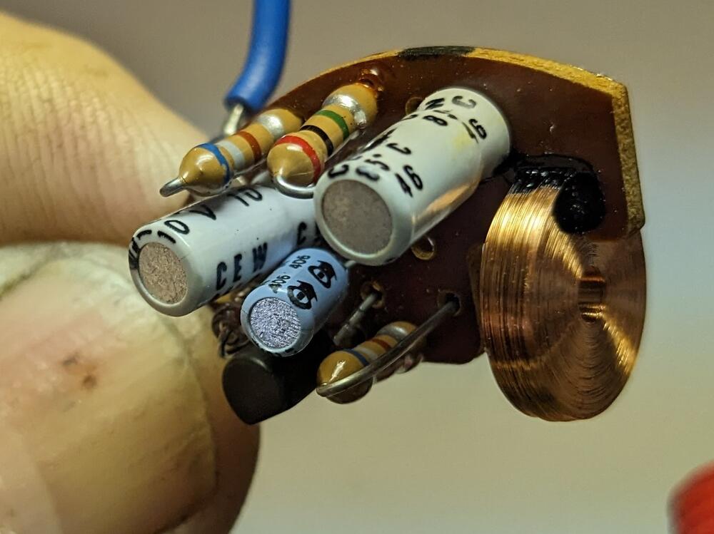
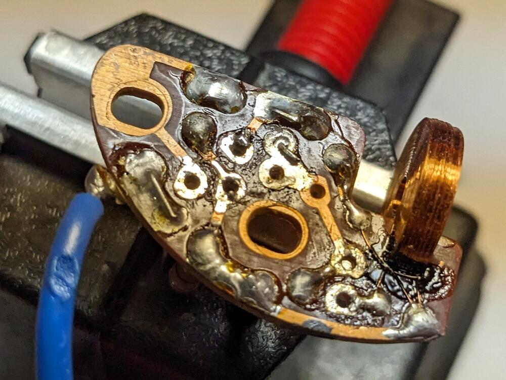
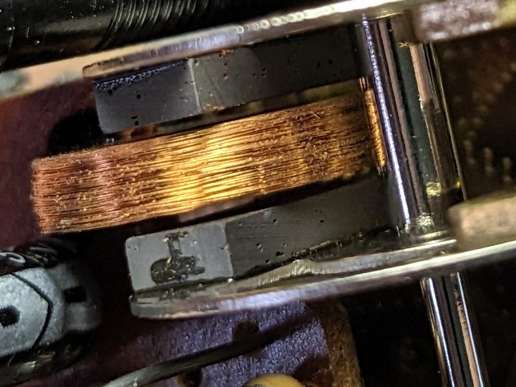
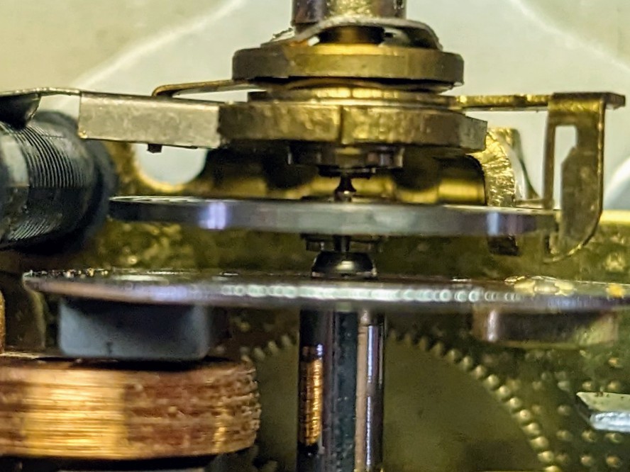
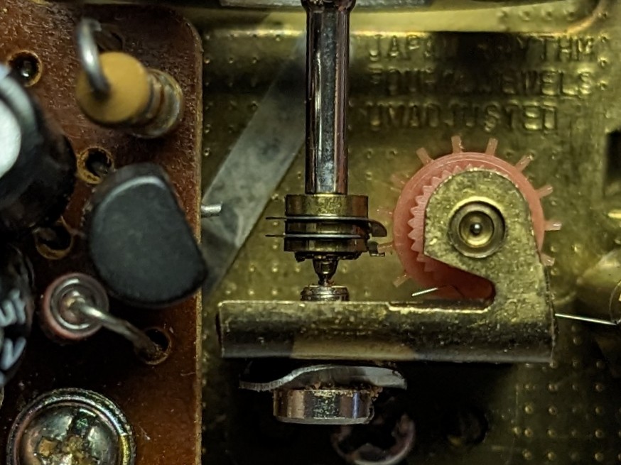
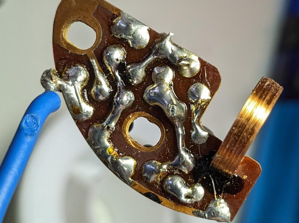
I have to assume it's a ceramic cap, no polarized marking. I used the Aluminum electrolytic caps, to be safe. With it all back together , the winding energizes momentarily. I checked the spindle centering (because I dislodged it during disassembly ) and that the coil winding is pretty much centered in the spool. I assume it doesn't need 12v to trigger it, since it runs off 5v.... Zener shows approx 5v output, so I don't think that is bad...
-
That's the problem with RockAuto - if you have repeat failures of a component, they count it against your account standing, which affects how they treat you overall. I had this issue whenI had 2 pairs of one brand of shock fail within a year of each other.
-
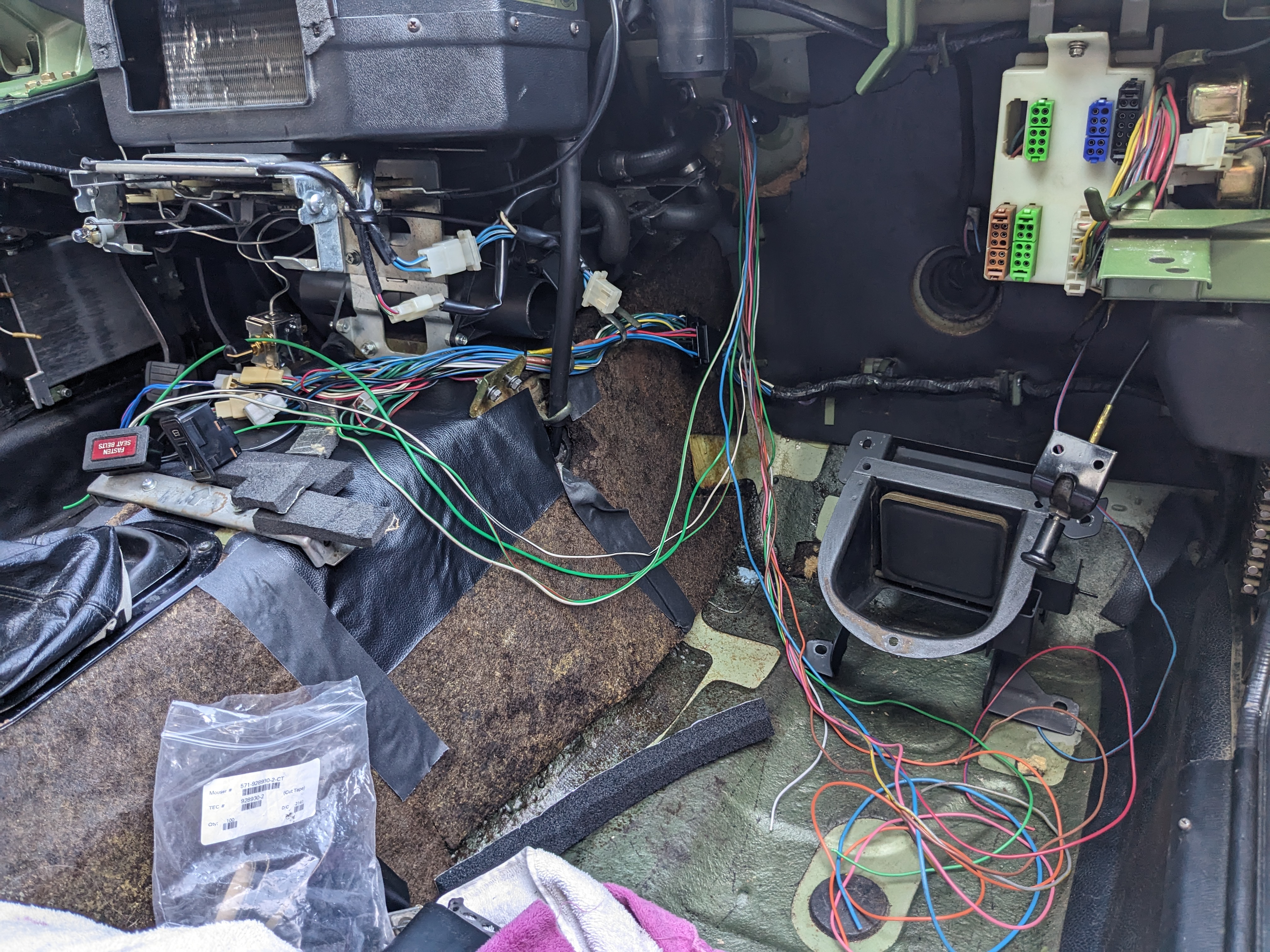
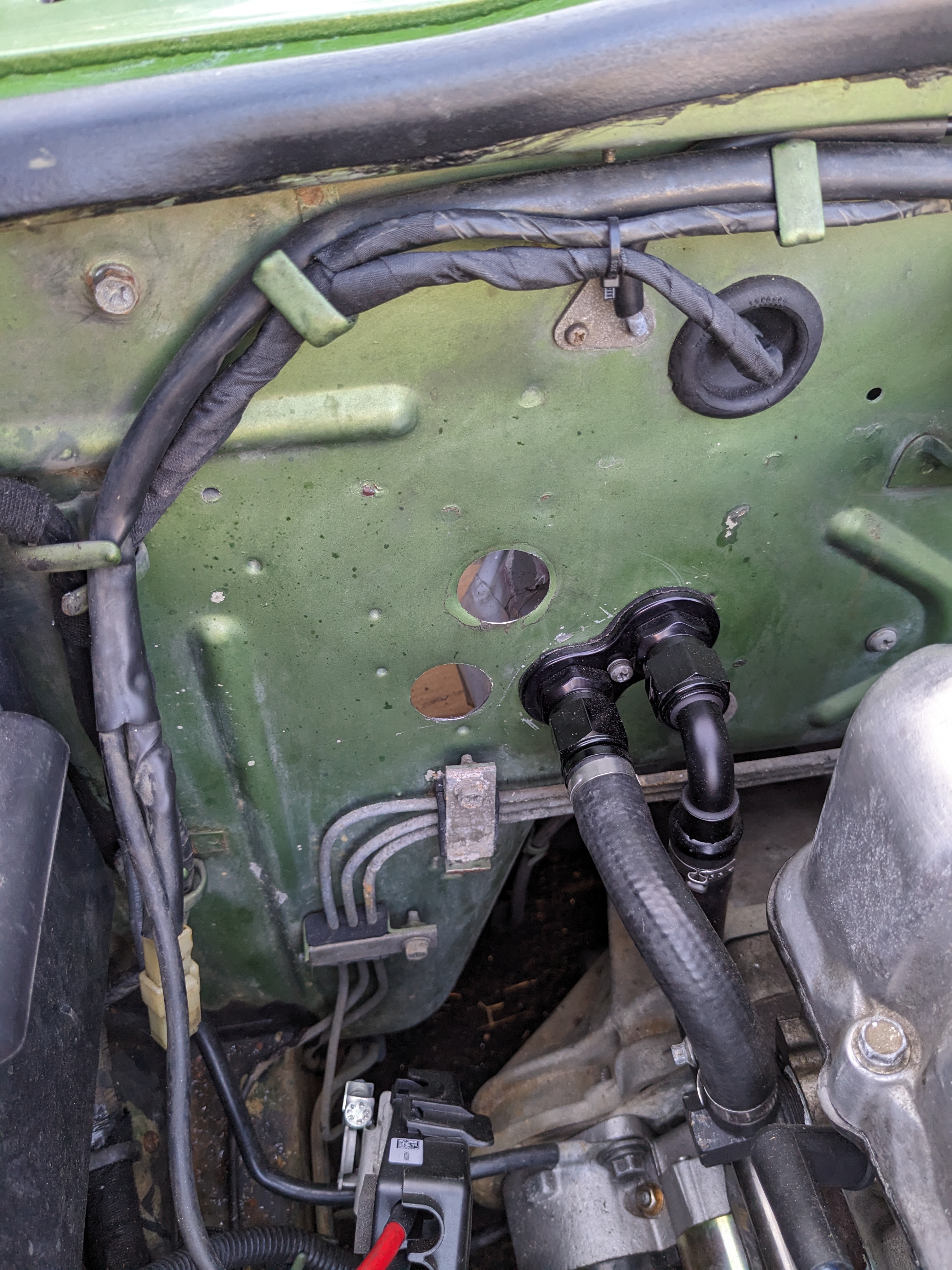
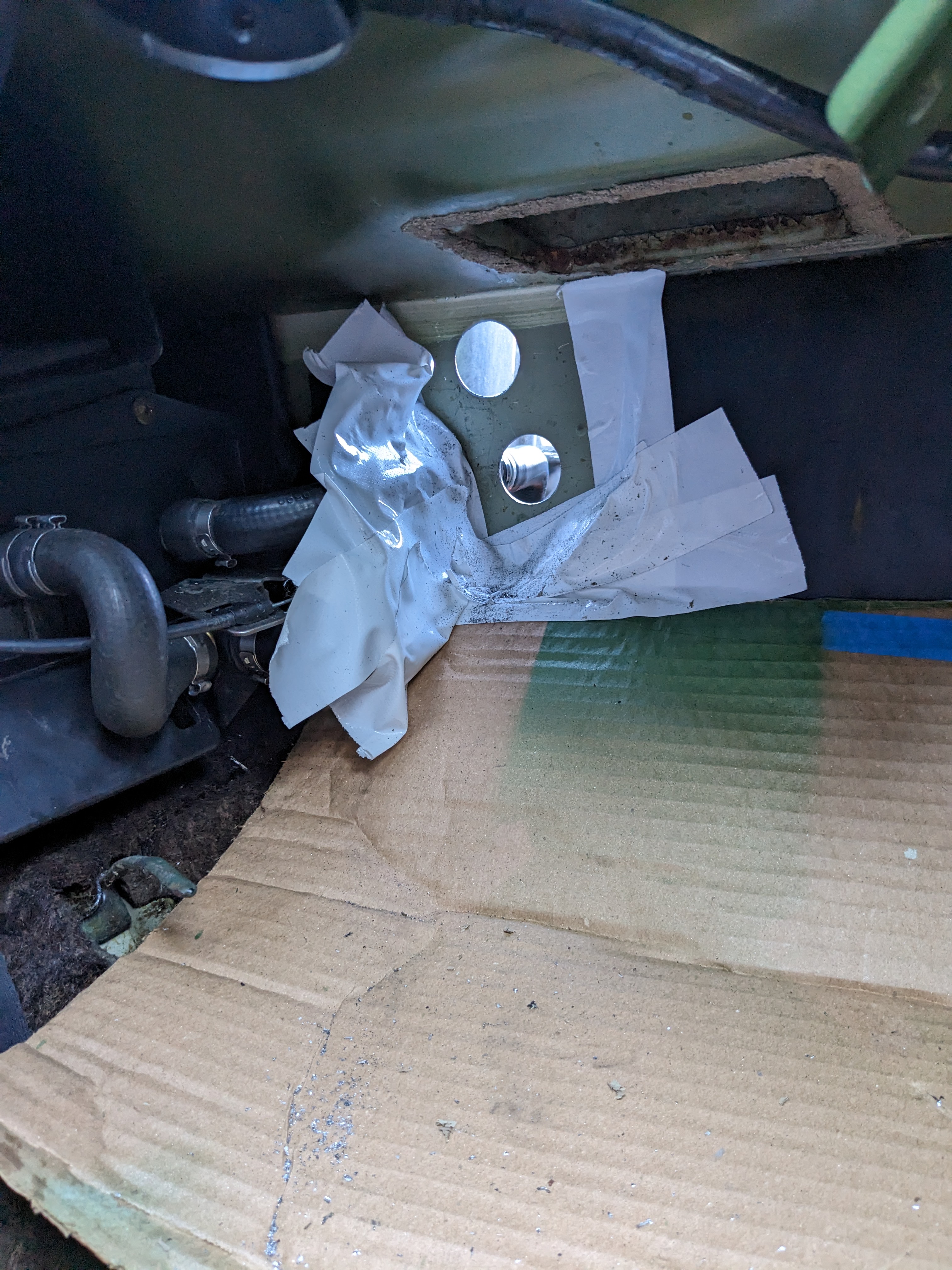
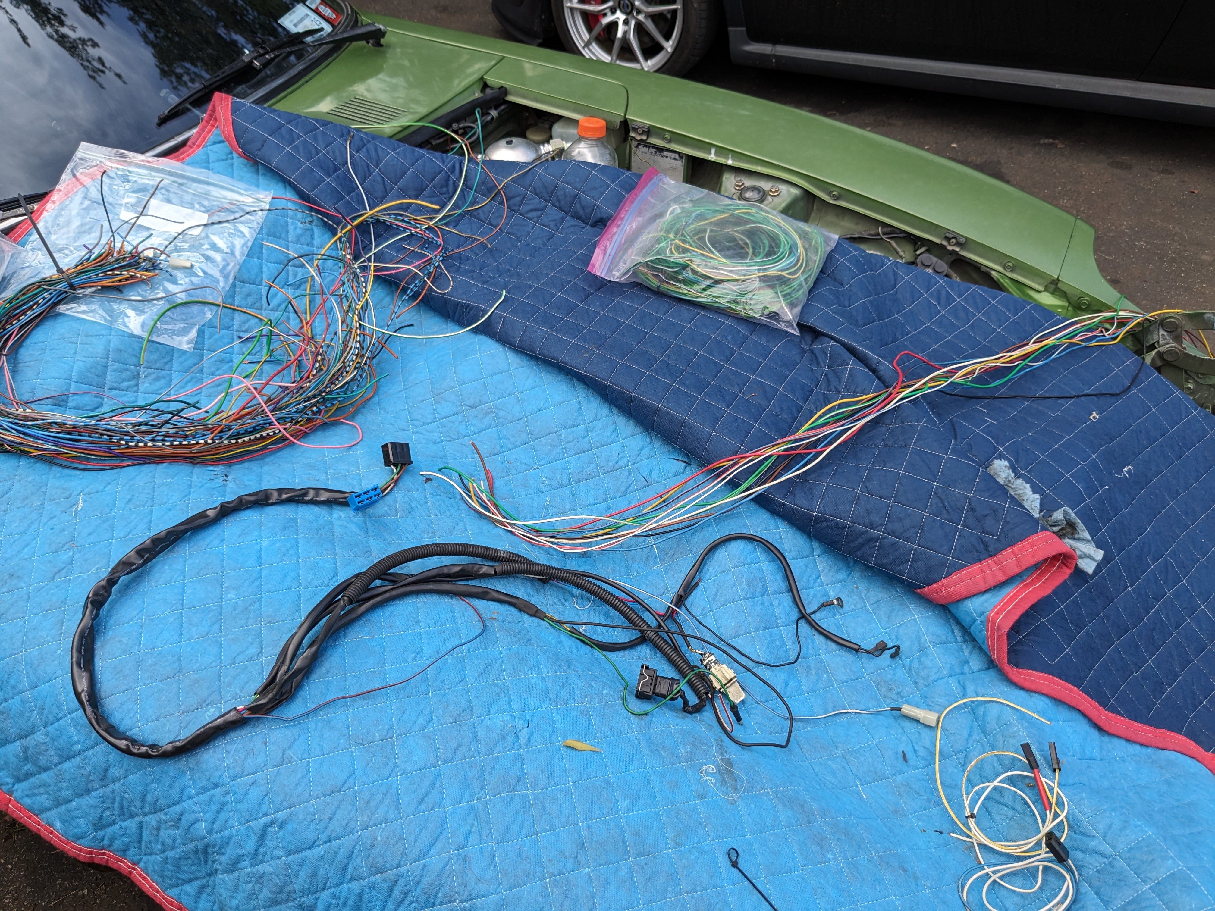
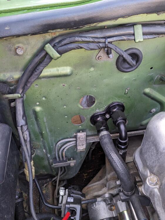
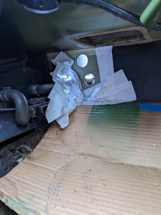
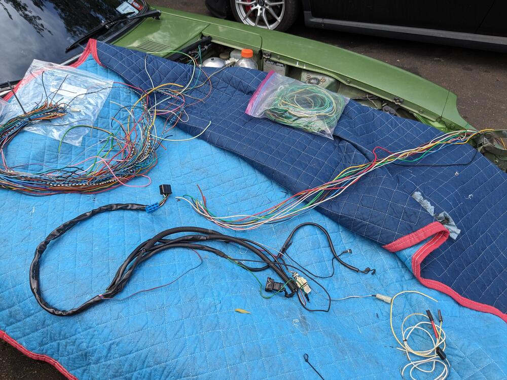
Enlarged the existing firewall spare hole near the heater ports to 30mm, and added another 30mm hole below it. One will be for the AC-related wiring & Bosch CIS system, the other will be spare for when I do the V6 conversion at some point. Using color coded wiring I've salvaged from a Fiat X1/9 and from a variety of Volvos figuring out suitable layout/routing. Have to remove the water port & drill & tap the old EGR sender port to 12x1.5 for the CIS ECT. I have various waterproof 2.3mm terminal/connector housings to use for the firewall connections
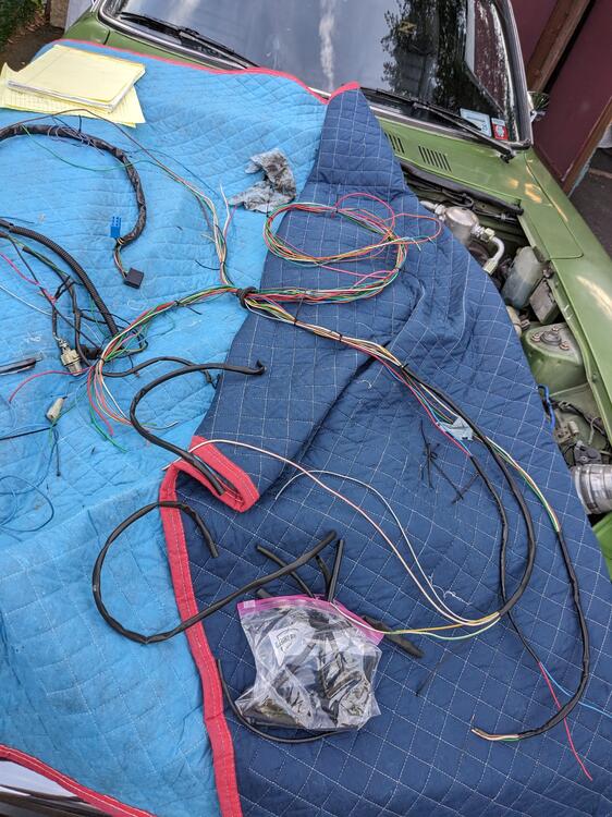
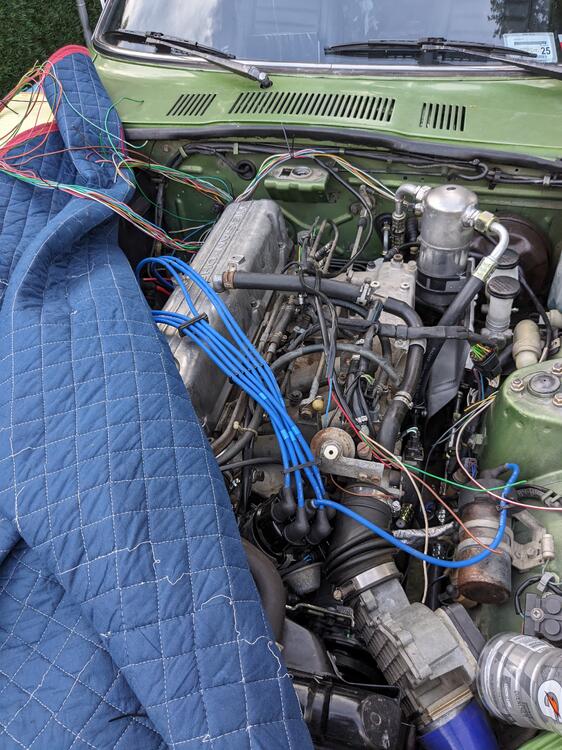
-
So, I went through my stash of components & found I have a Tantalum .22uf cap, so I may as well use it instead of a plain aluminum cap also dug out my work station so I can hopefully see wtf I am doing also have some zener diodes, so I can replace that also if need be
-
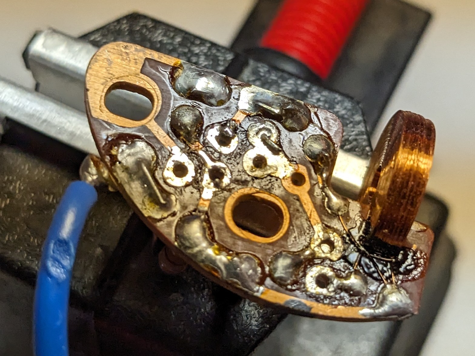
No, no movement at all. Thanks for the vid - I have wicking braid & a fine tip soldering iron I haven't used for many years - I used to solder chip pads into 90's Volvo ECU's in order run programable chips, but that was many years ago, and I have had to wear prescription glasses since 2012. I have to dig out my light table/magnifier so I can be careful with the coil winding, so thanks for the caution there.
-
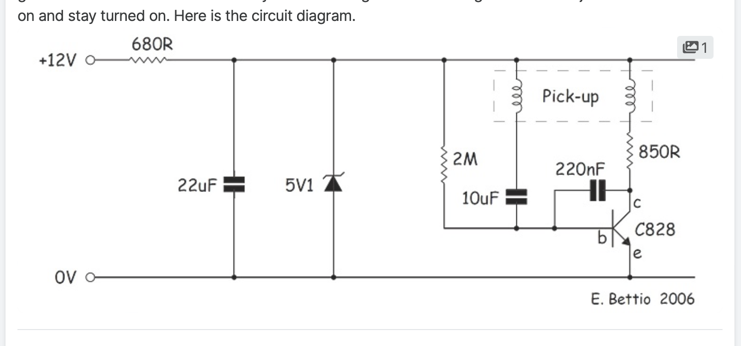
Yes - across the I/O board connections - when I connected a 9V battery to test it, I register 9V across the circuit with my multimeter. Another electronics guy said the caps dry out & fail. His suggestion is to first replace the 3 caps on the circuit board. What did you do? EDIT - when I saw your post, I only registered the 2nd half, after your quote. So, yes, I'll do the caps first & go from there.
-
Thank you - so, did you just replace all the capacitors, or start with a particular one? No idea how one would circuit test a capacitor, if it's possible?
-
Yes - stone dead. I seem to have continuity across the circuit, but perhaps that's not the key. The mechanical aspect seems tobe all intact, no binding, etc. the shaft with magnetic(?) weight/wheels spins freely & will oscillate if manually activated. I'd really like to fix it rather than gut & install more modern internals(did that with the Fiat X1/9). Appreciate any input Captain O!
-
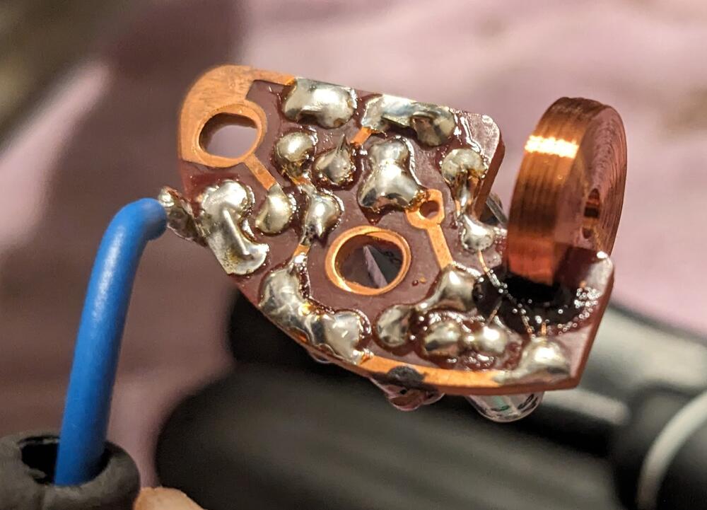
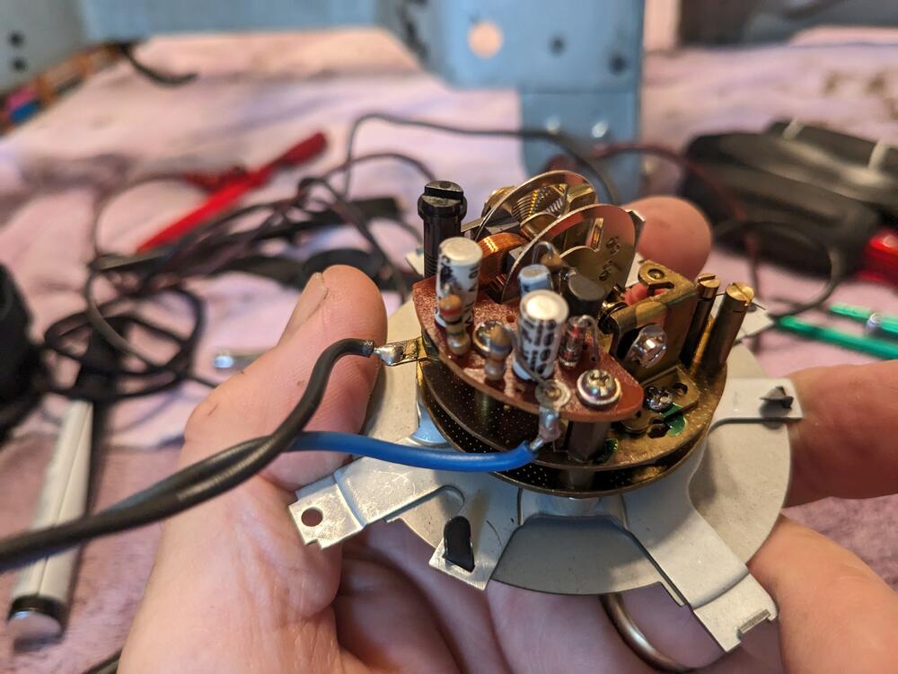
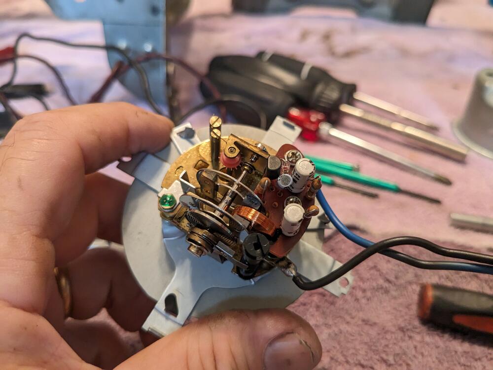
Found a thread on a 77 280 that showed rebuilding a Quartz clock, and referenced rebuild instructions (for the earlier type like mine?) without any link EDIT - found this thread linked searching on another forum - says 70-78Z, however I can only assume they never took apart a 75 version as it looks zero like the pics of the motorized version he shows (later in the thread) & describes repairing Before anyone mentions it, I'm not paying ZClocks $351 for a rebuild. circuit diagram posted on other forum - don't know if its accurate Has anyone found a common failure / repair point for this? I con't see anything blatant with the mechanism or the circuit board, but it doesn't work when I apply test voltage by way of a 9V battery
-
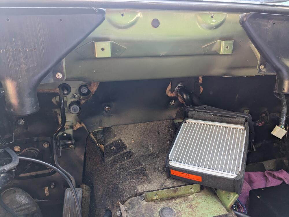
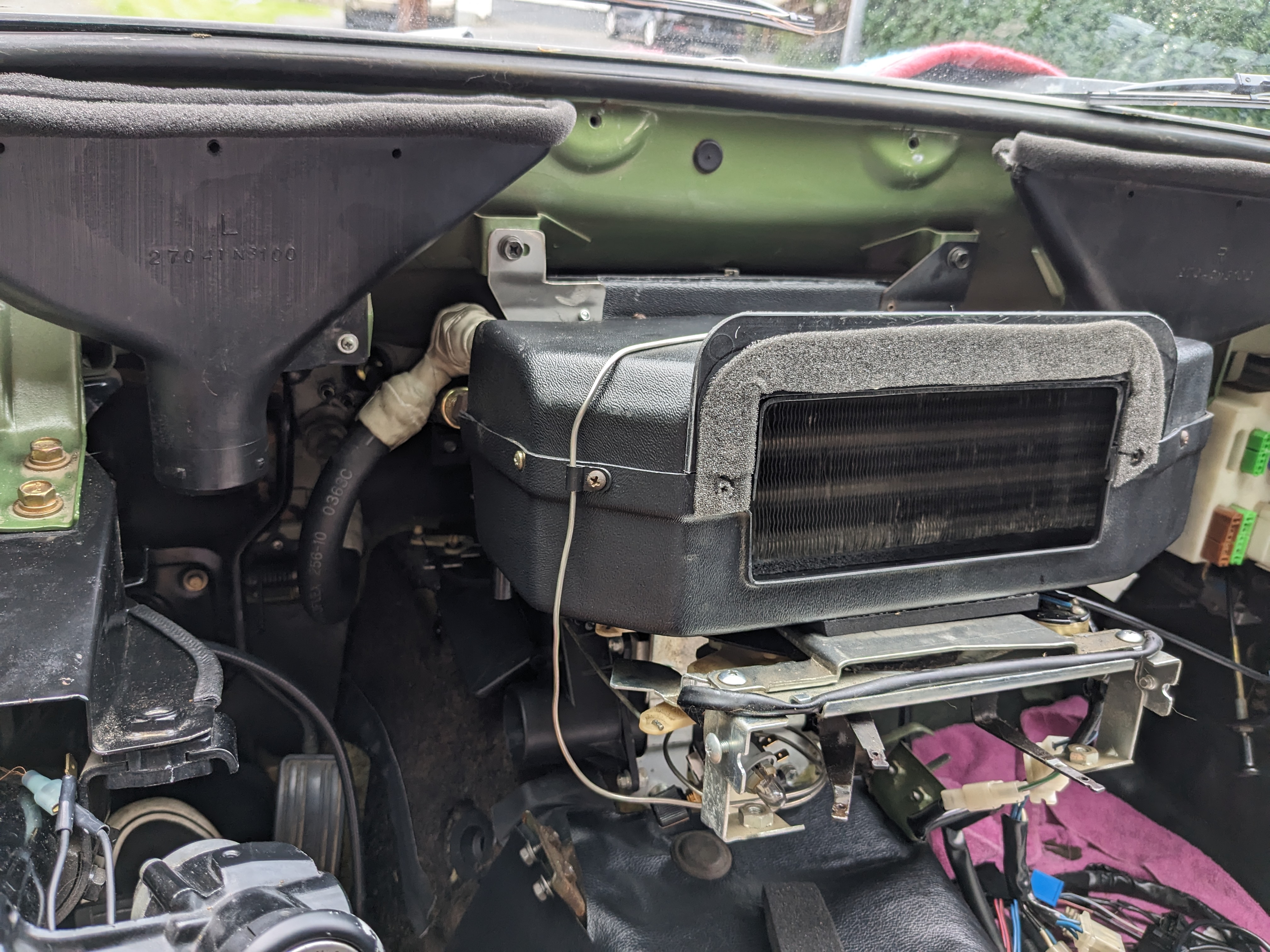
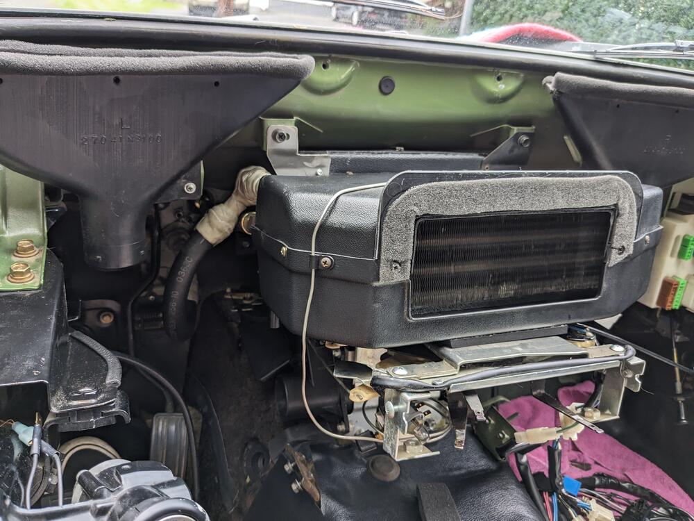
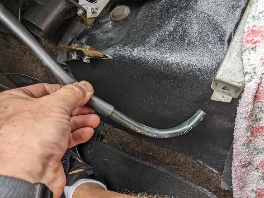
Put the controls & evap box back in, connected the AC lines. installed the capillary tube in the center of the evaporator, inserted to full depth. The old one was shoved about an inch into the duct side of the core, not doing much in the way of registering core temp. As the PO said, the AC never worked very well. Need to get the AC circuit wired so I can wrap that aspect up. fixed the evap box drains by adding a elbow that is rear-facing, so air won't blow up the tubes when in motion.
-
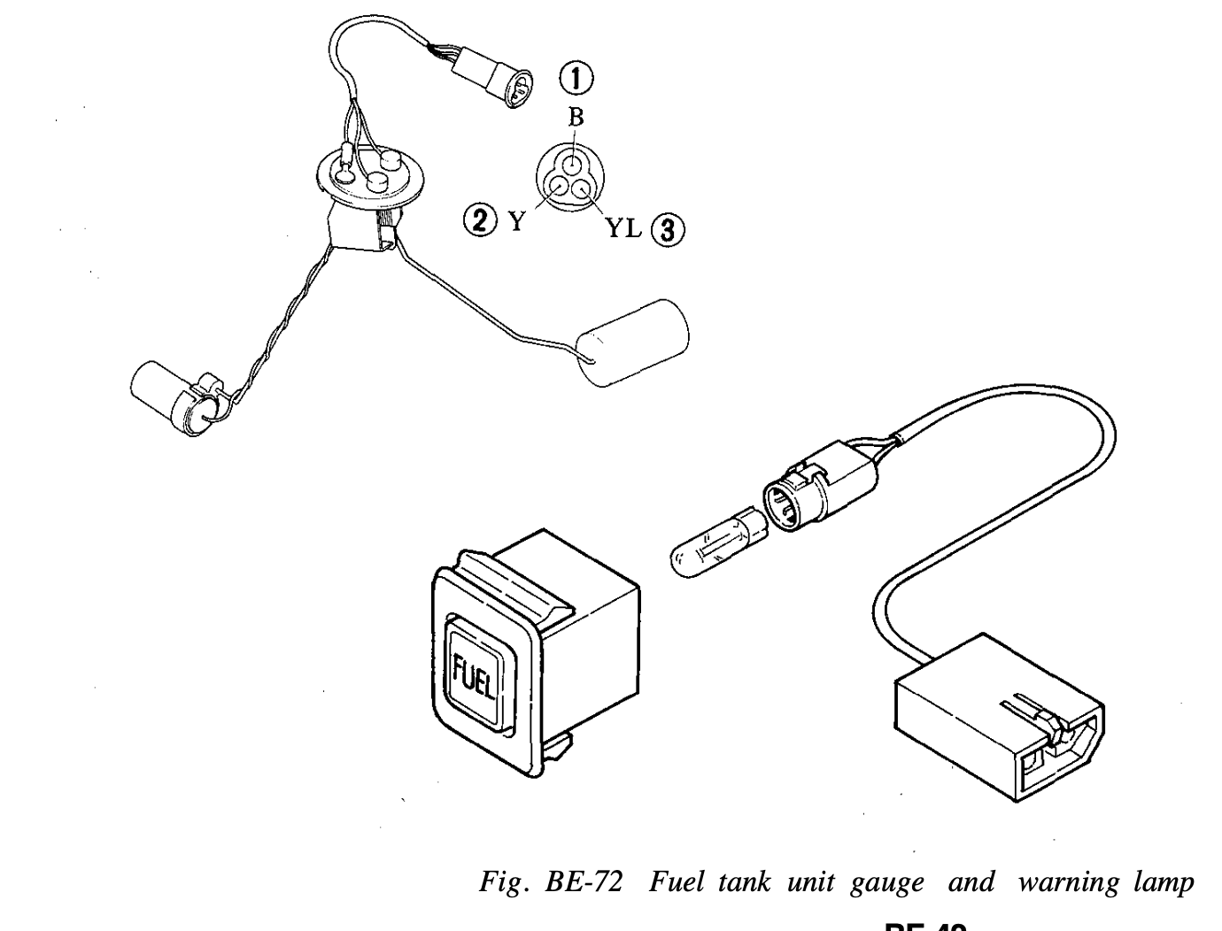
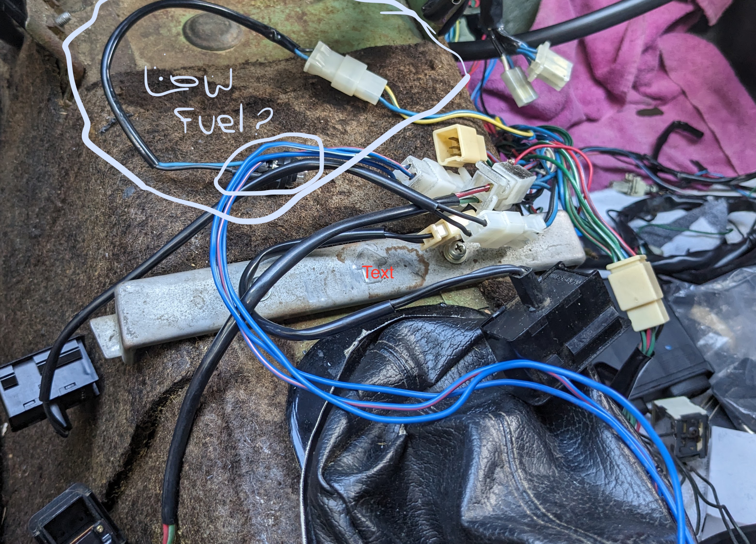
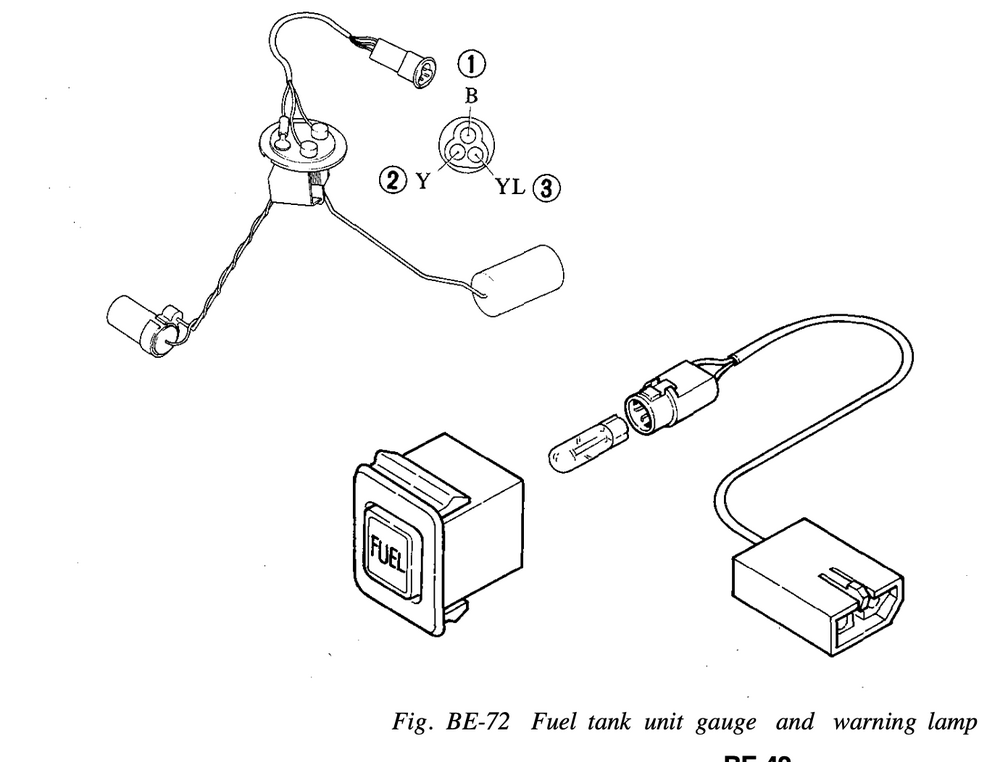
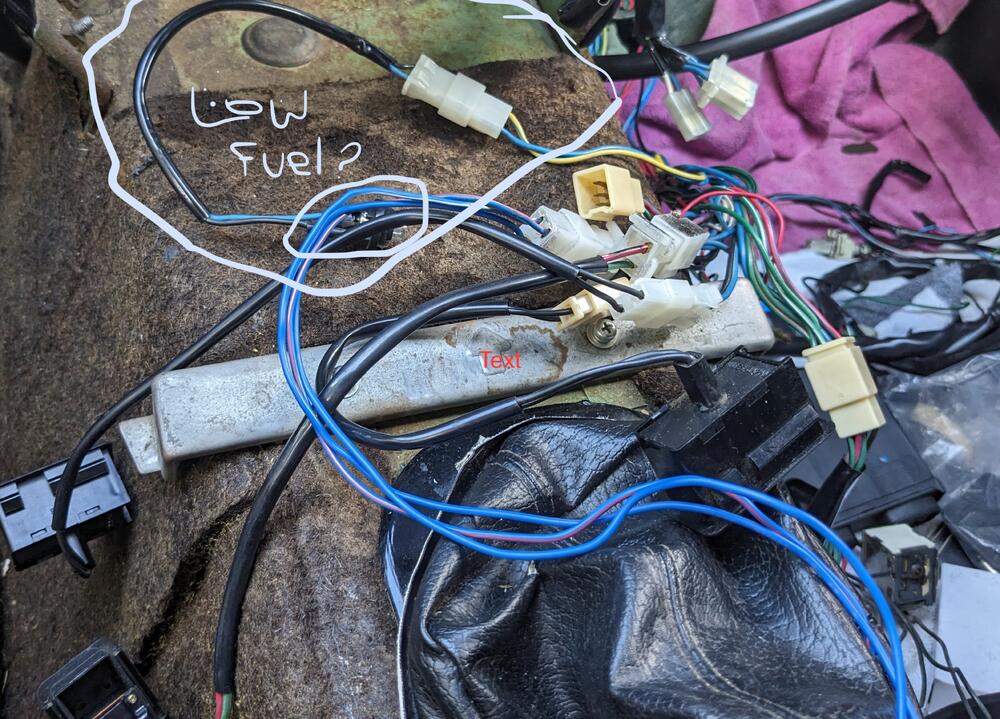
interesting - there are wires taped up in the front crossmember /valance harness, I've not examined them, but presumably those would be for fog lamps then. I don't see any mention of them in the 75 FSM though. Another thing I've found - the harness & bulb holder I've circled seems to be for the low Fuel indicator lamp (yellow/blue , blue) = which I don't have. I'm assuming it was a small square lamp in the console below the radio, but that's where the AC thermostat was installed, so I guess they simply discarded the holder 😞
-
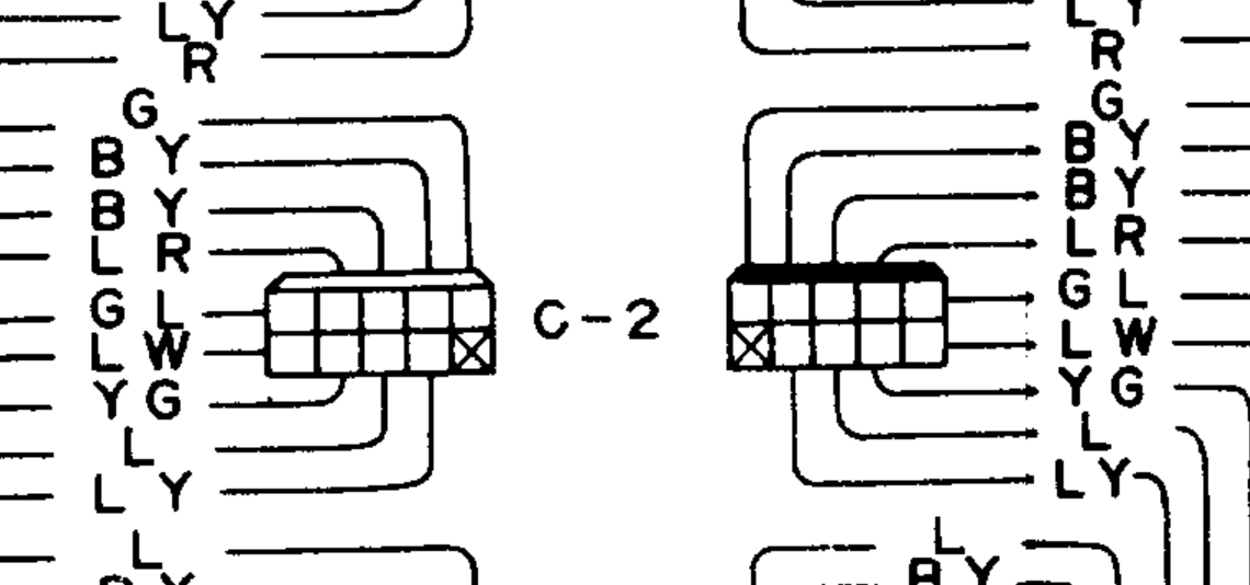
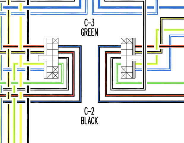
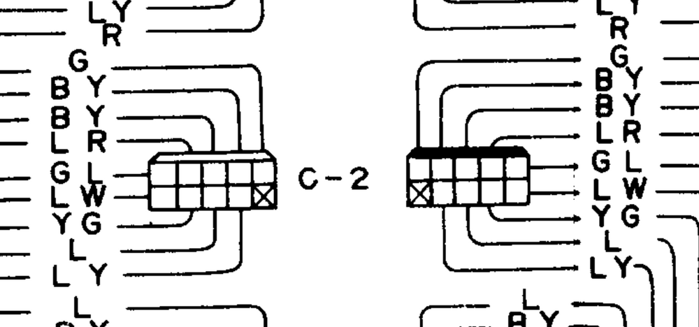
Thanks Steve - as far as I can tell, everything has to come through the Cx connectors. I would pull from there before adding load to the ignition switch. I have a good supply of 6.3mm crimp terminals & housings - both Volvo and Fiat used them back in the day 🙂 My main issue is the Nissan wiring diagrams make zero sense to me - I can't read the connector pinouts for the life of me. I'm assuming what's shown is either side of any given connector - C-2 in this case. Can't tell which side is body & which is harness. I'm used to diagrams that indicate the pin numbering - since this is 14pole - the diagram (for Volvo for instance) would indicate 1-14, so it would be easier to negotiate the diagram & corresponding harness wires/colors. It's gonna take a while to get used to these.
-
Thank you Steve, found it! Also used for spark advance/retard (that I don't have). I'll leave those alone for now. Going to have to memorize the wiring color convention translation 🙂 Clock & Cig lighter (LW = Blue/White) appear to be constant (30) vs. switched (15) power sources, so neither would work for the 3-pod gauges (WBO2 controller, Oil temp, Volt) I'm adding. OK with those (Red/blue Green/white) wires, all four were bundled & taped inside the harness conduit, so I assume they all go to AT related indication. So, I presume I could repurpose those for gauge illumination, looking through the illumination wiring, they do not appear to be conditional upon other parameters.

-
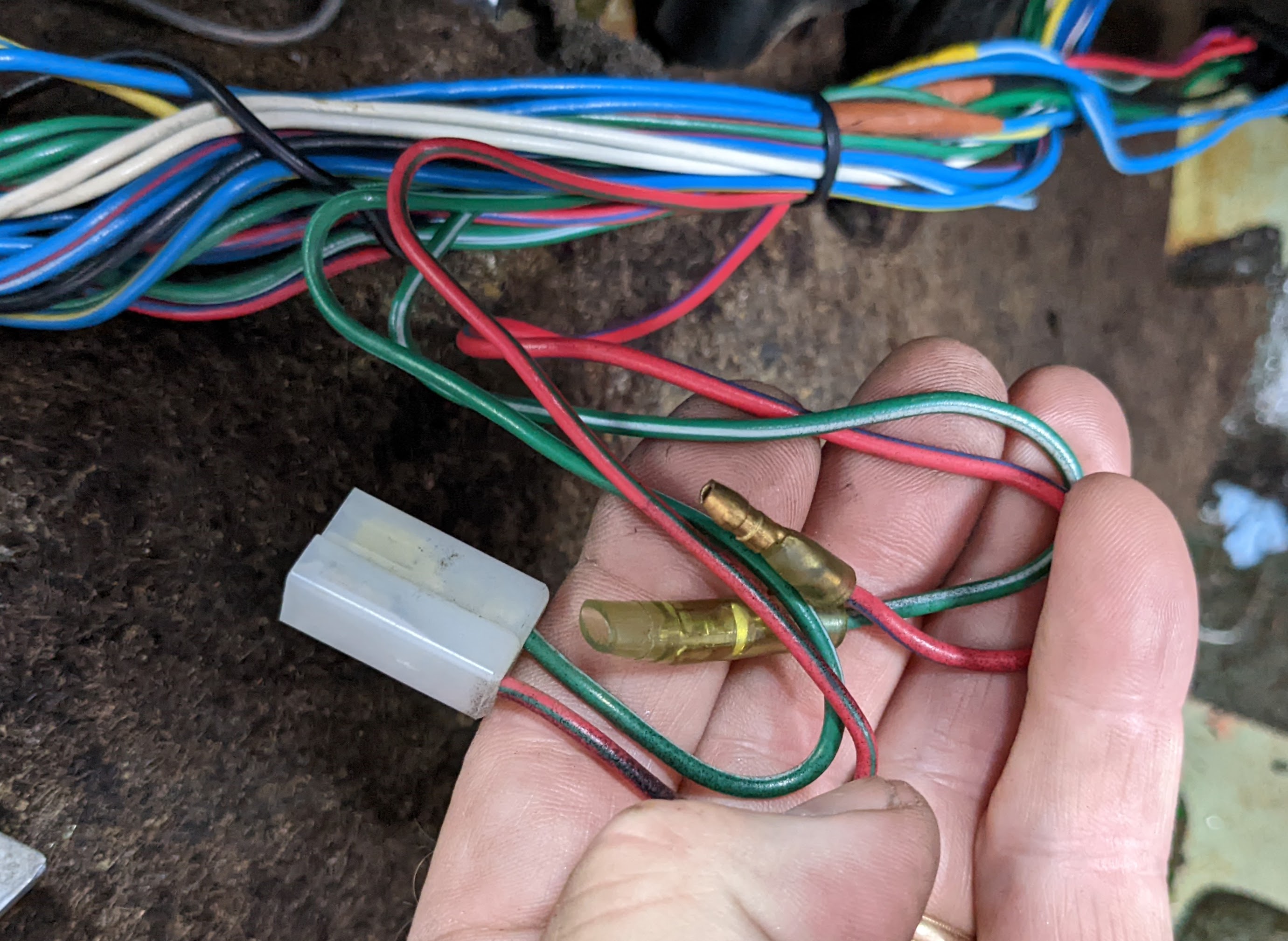
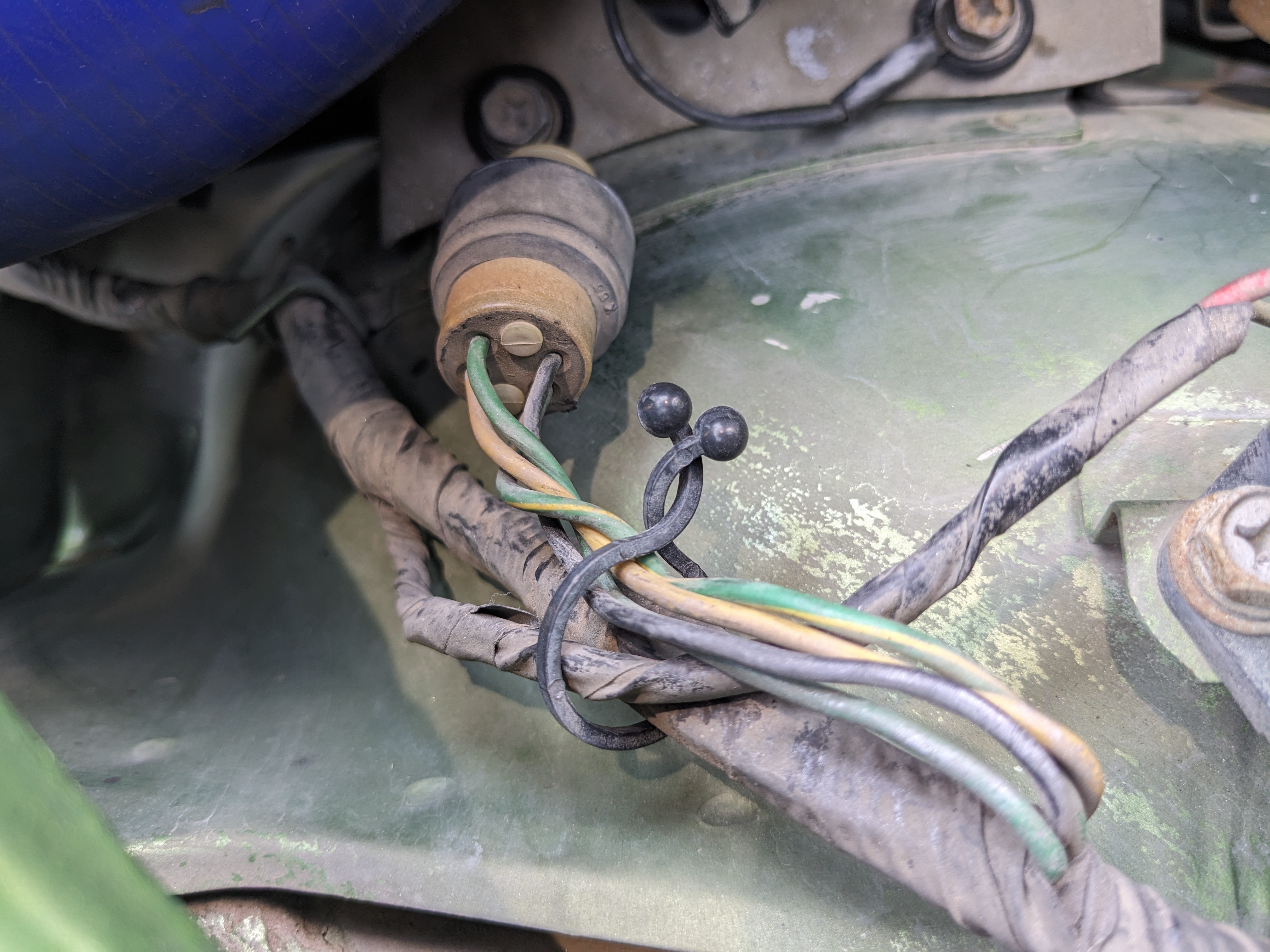
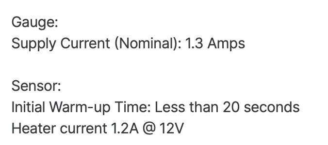
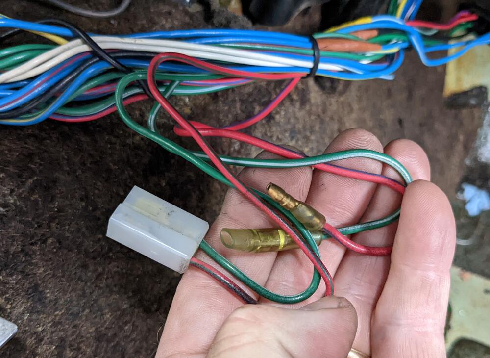
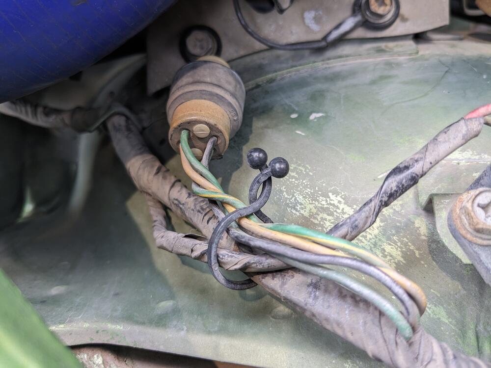
Thank you for the reply - those colors correspond to the connector in question. I would rather the Voltmeter be on a circuit that shows the state of the battery, than on a circuit that is subject to transient changes, so I need to check that. The AEM WBO2 controllers do not draw much current (from the manual): EDIT - I do have another couple wiring questions - these two sets of wires are also in the center console area. and this unused 6 pole connector is next to the ignition terminal block any ideas as to the purpose? I'm wondering if I can repurpose the 4 wires in the 6 pole connector, but I have no clue what circuit they belong to
-
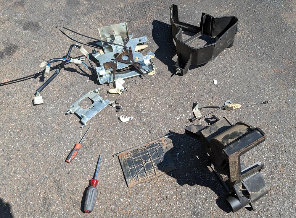
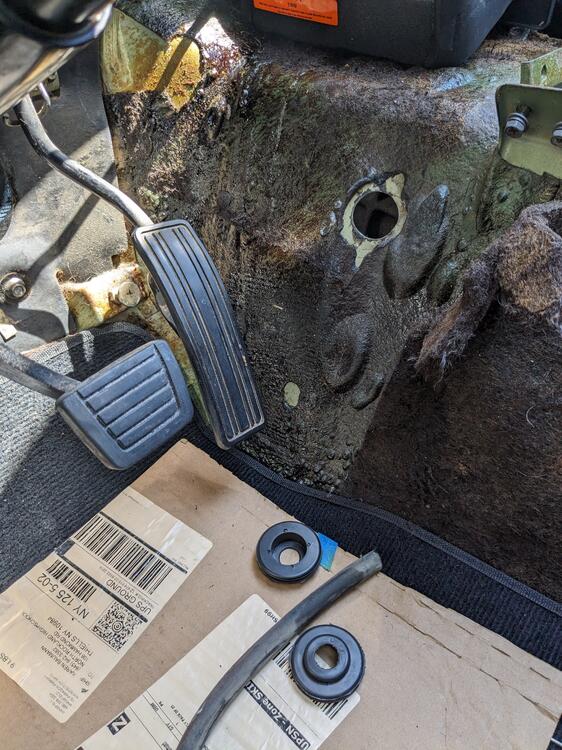
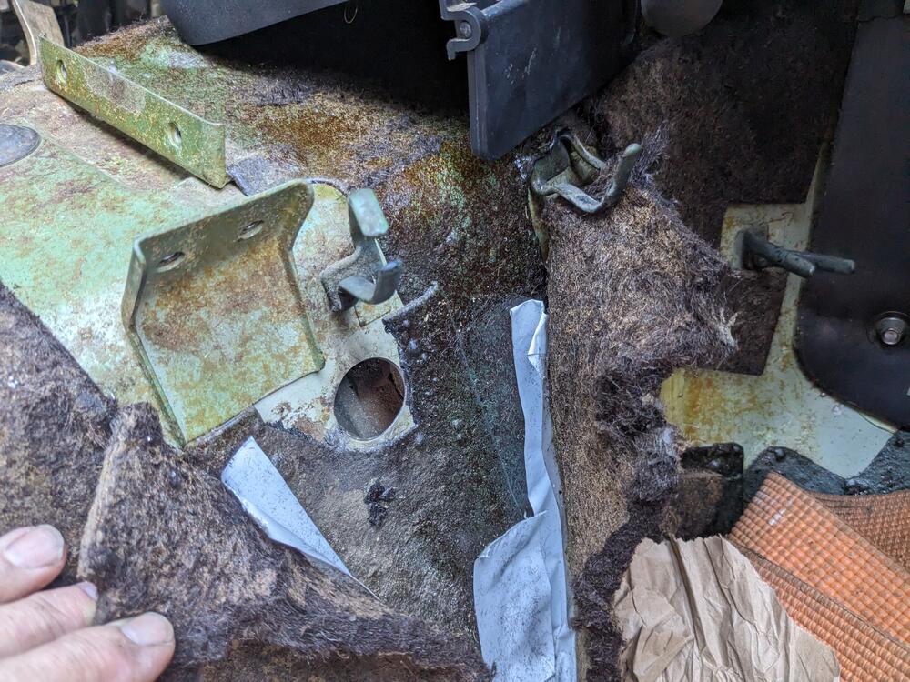
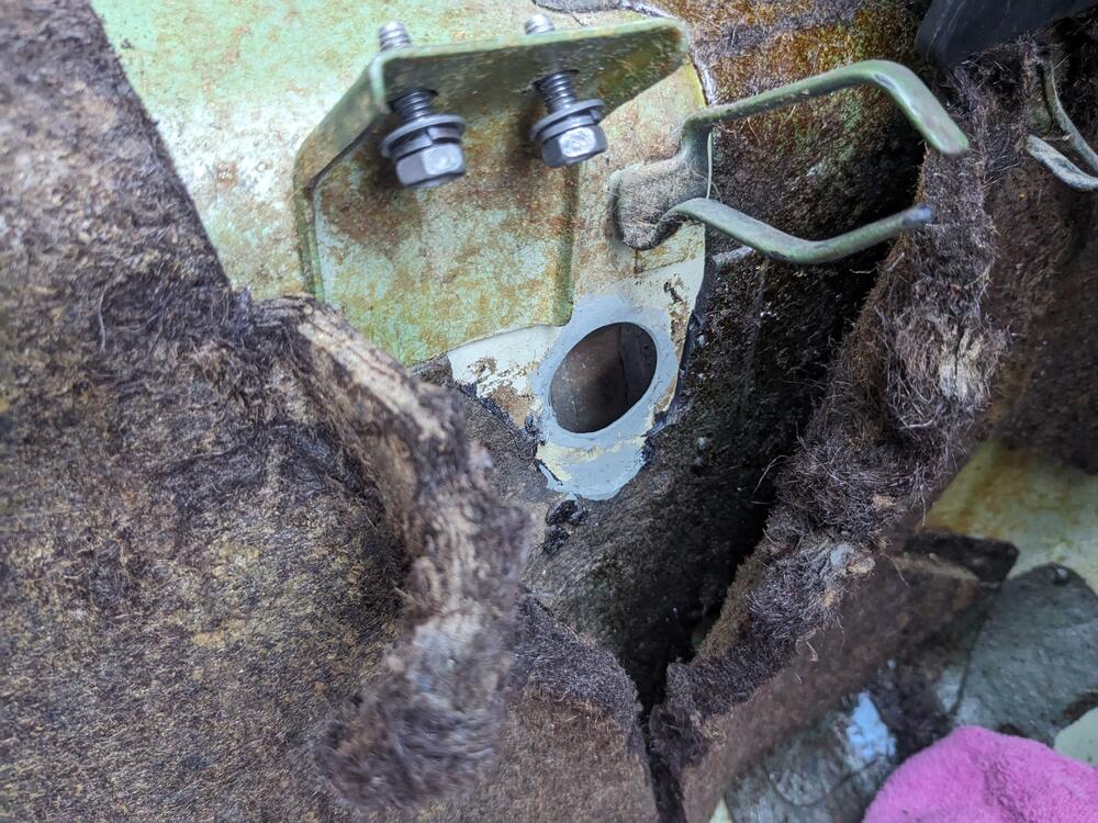
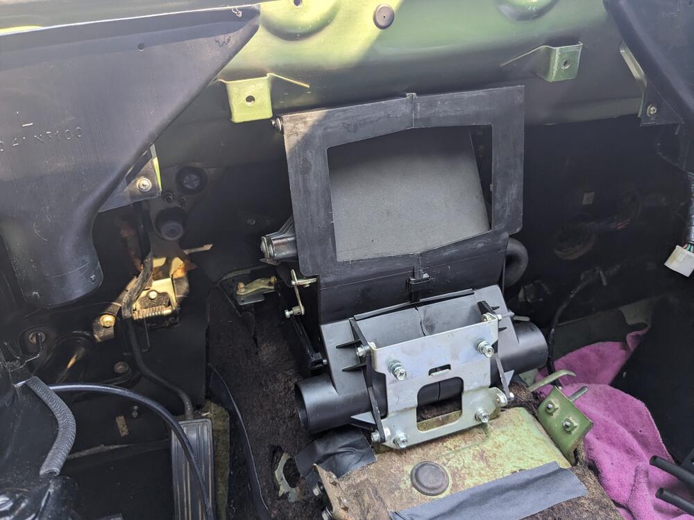
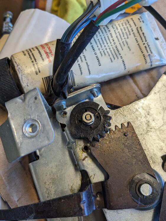
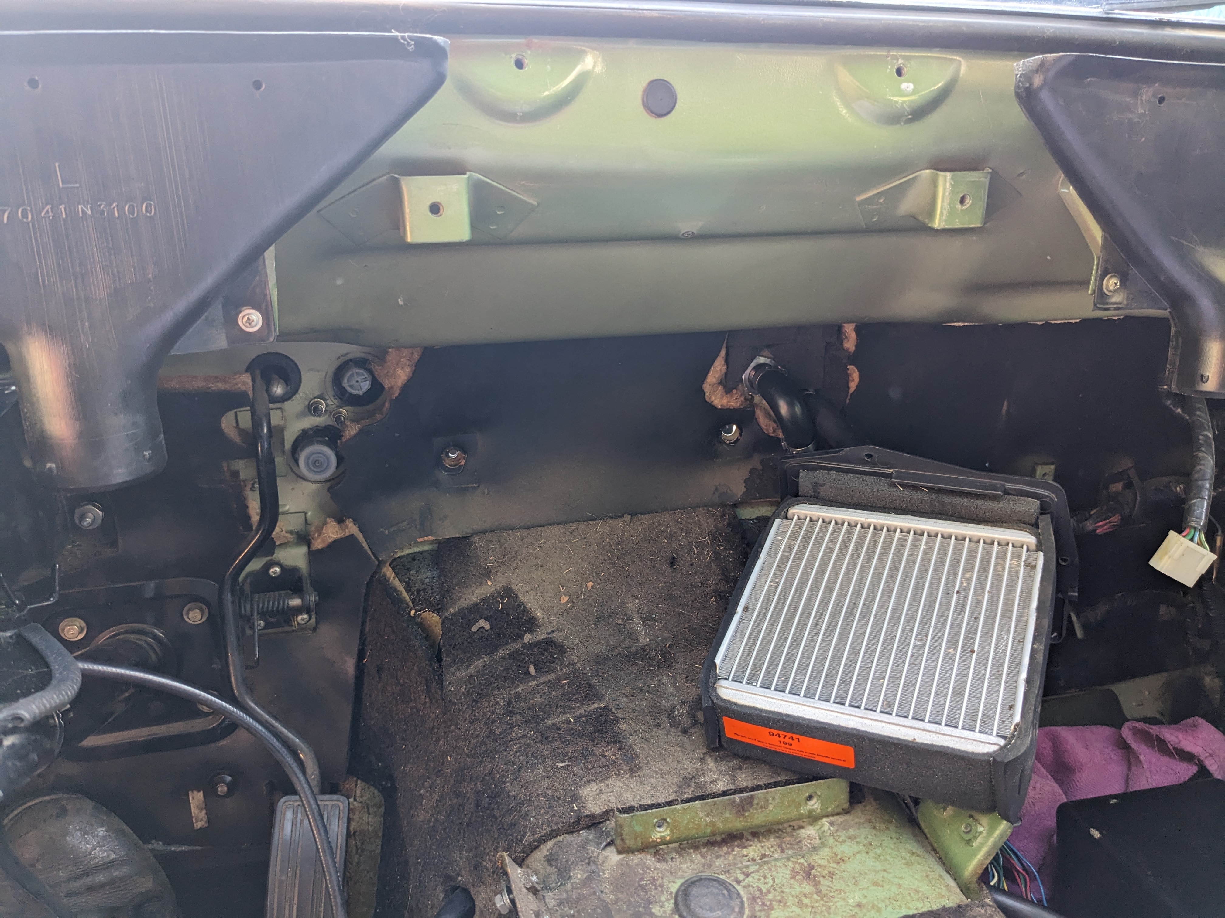
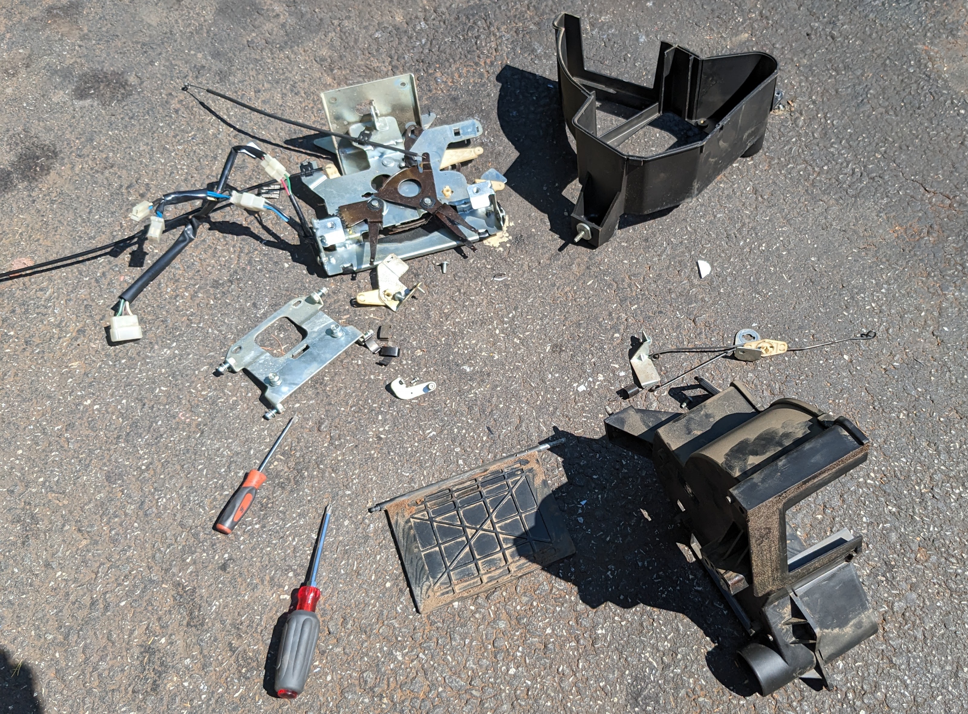
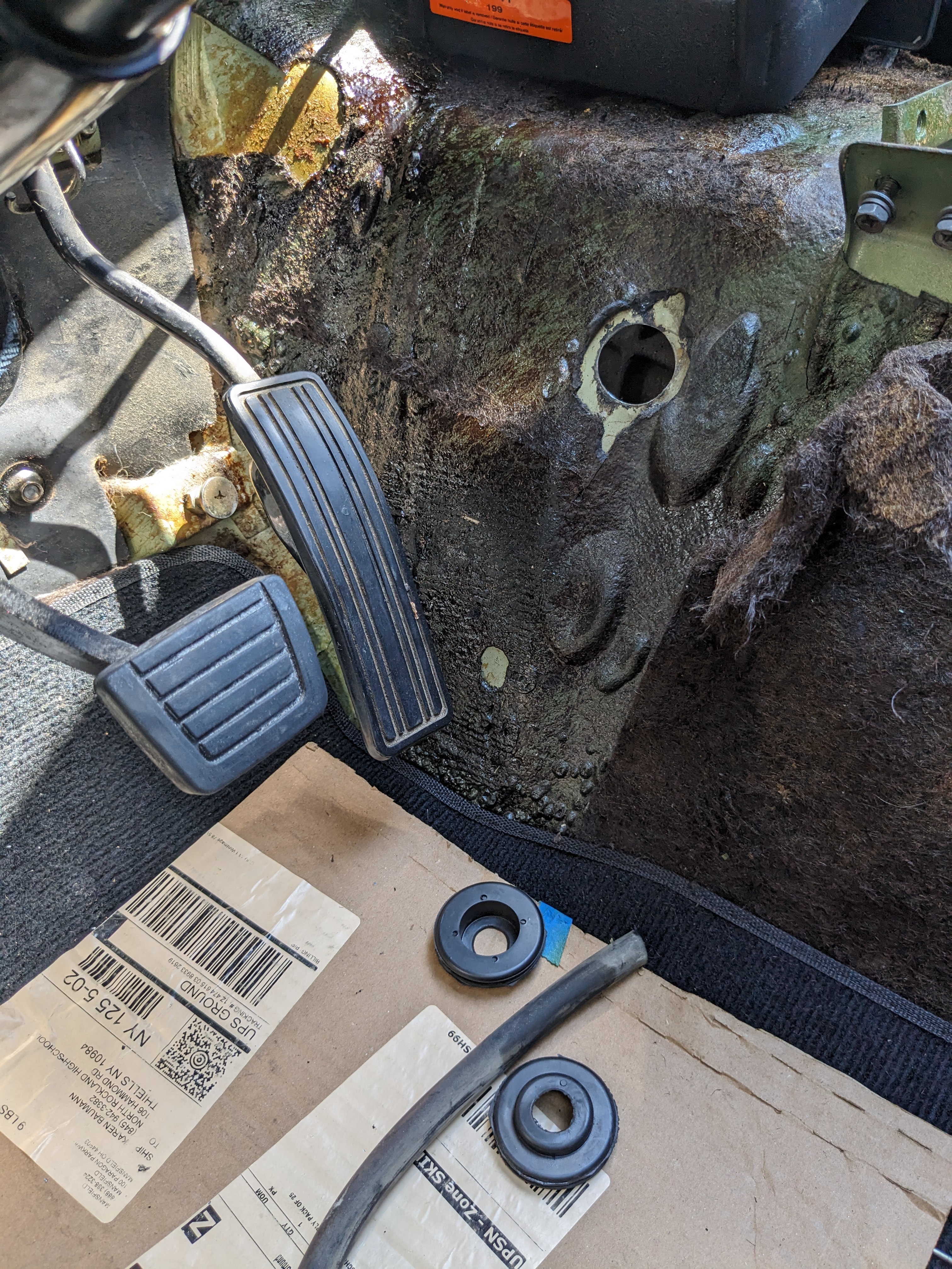
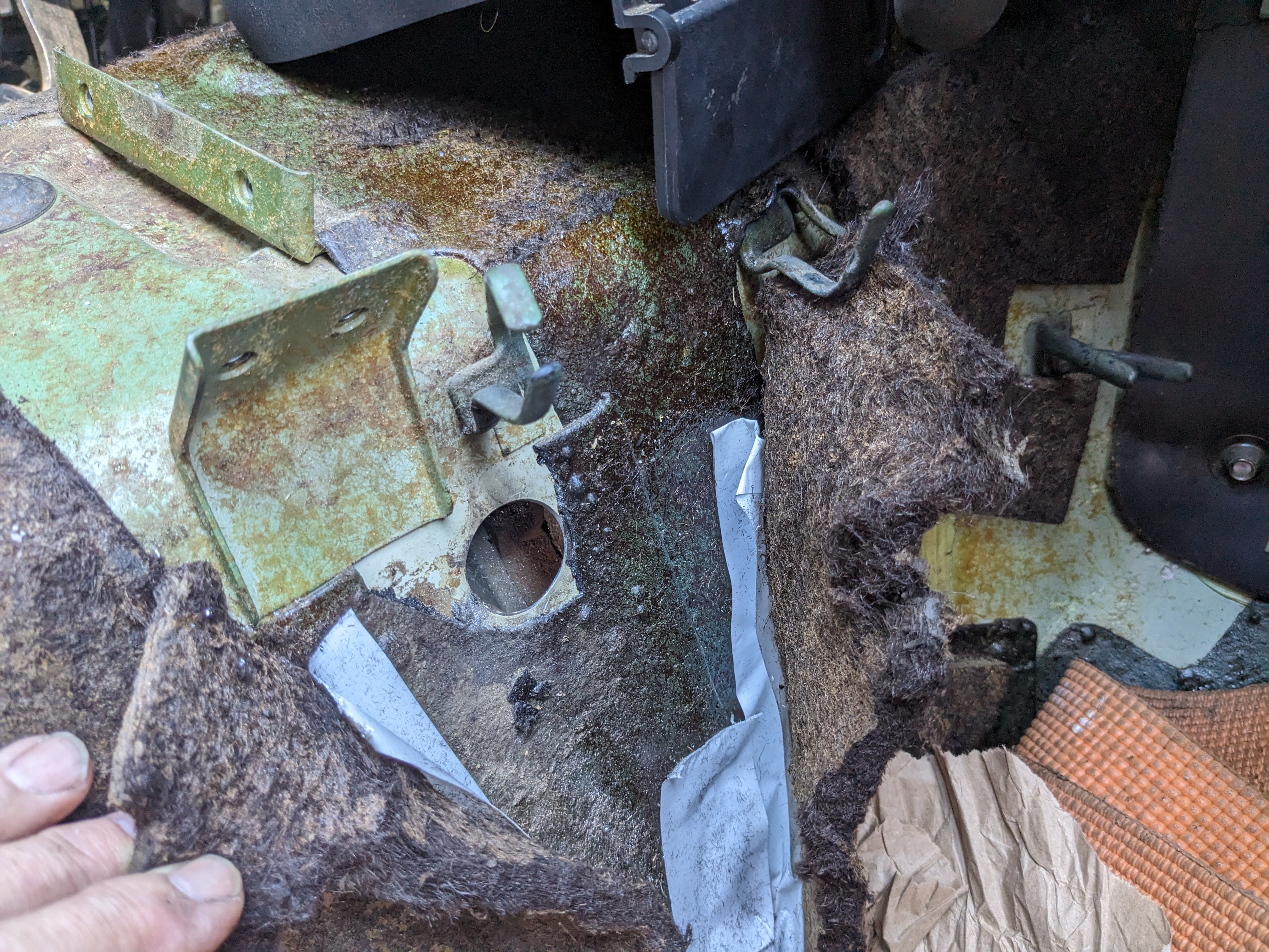
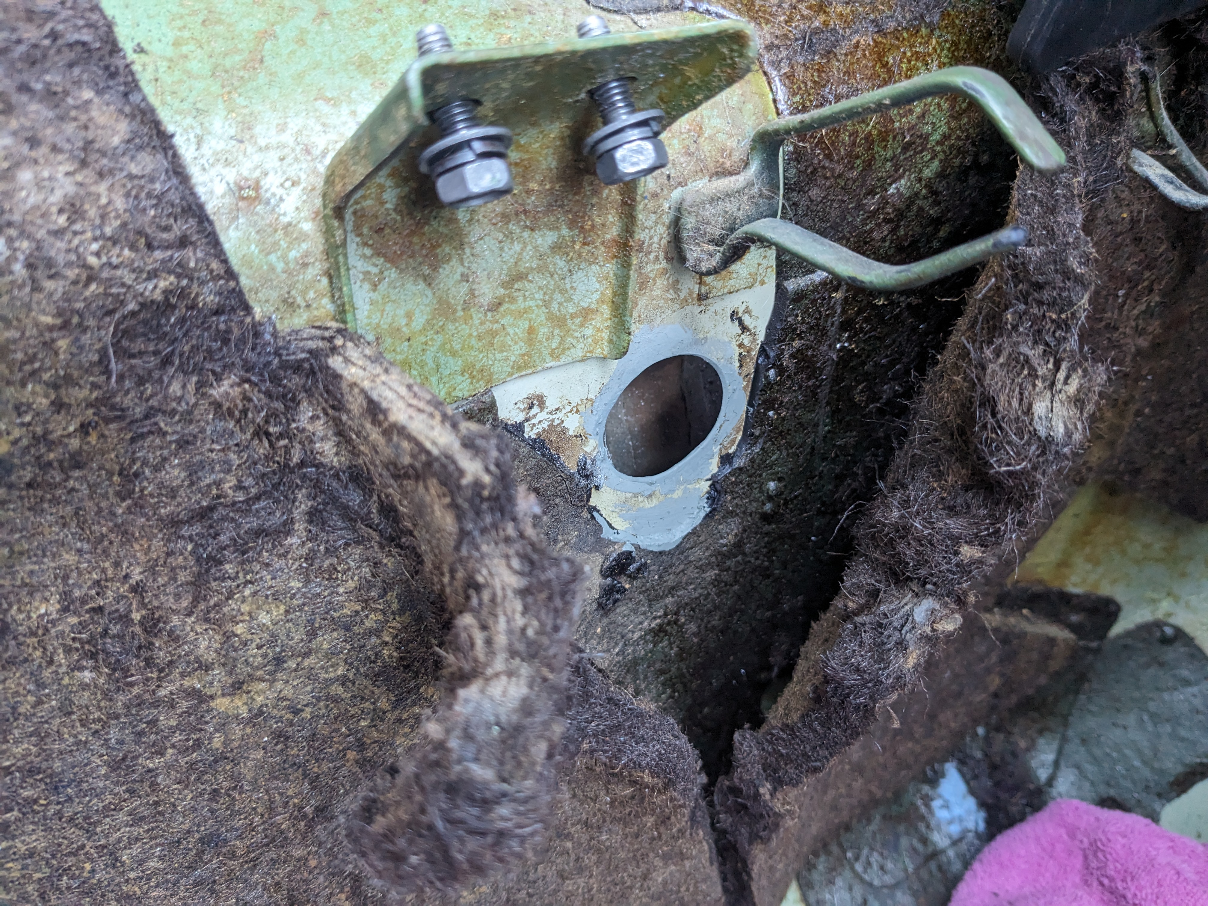
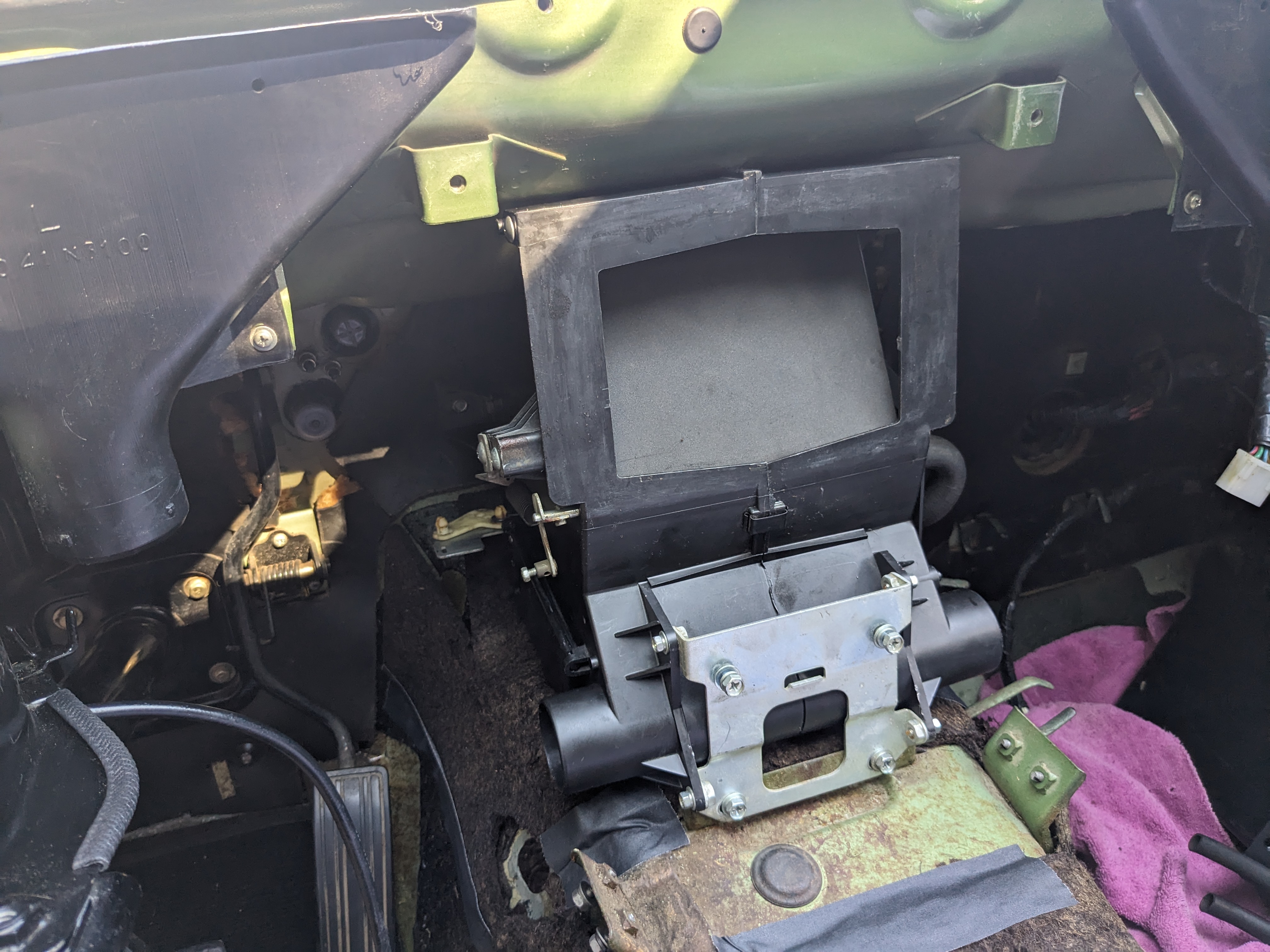
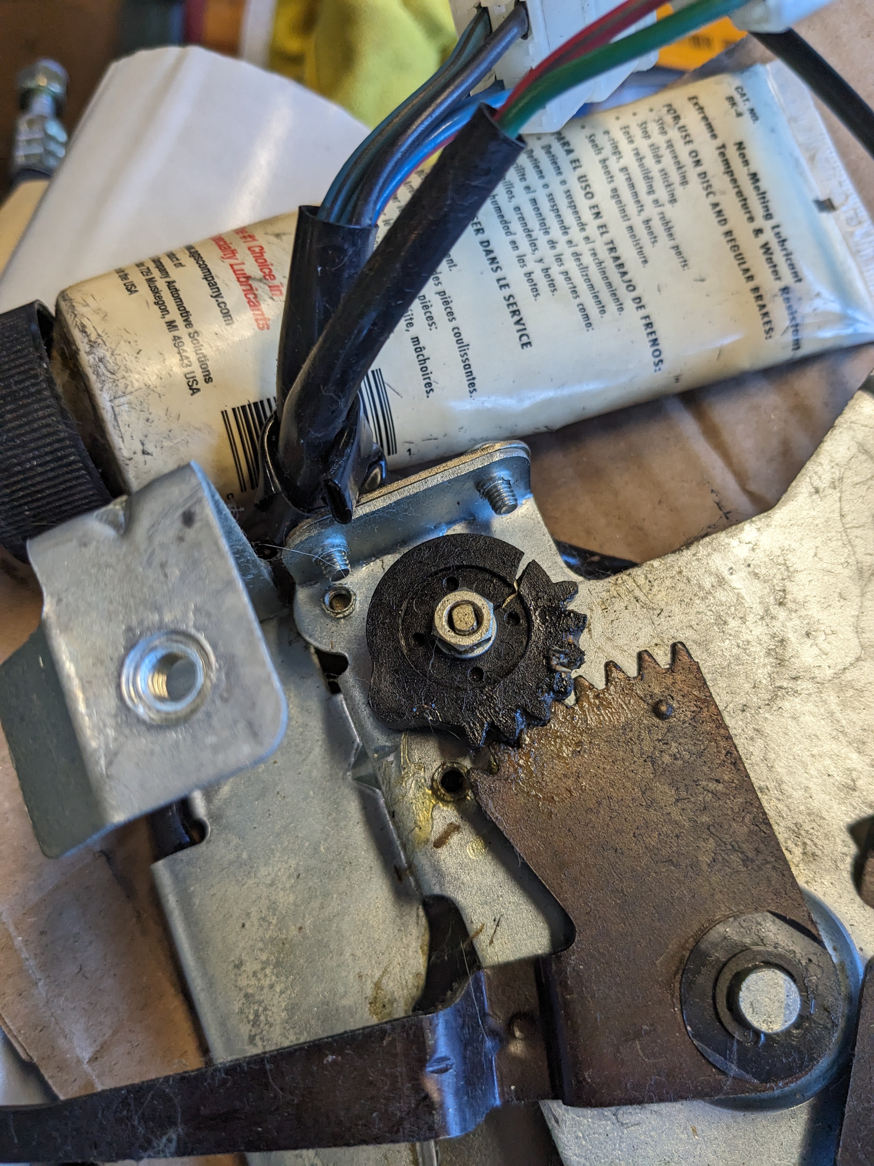
Removed the heater box stripped to replace the foam on the door (and clean) the other thing I've been avoiding is the holes they made for the evaporator drains -the ARA unit has a drain on each side. So, they punched a 1/2" forward facing hole on each side of the tunnel, apparently with a pick. The only way to address it is to drill new larger (30mm) holes that will accept a grommet for the drain tubes rot pass through primed & painted after that I put the heater box back in In removing the control panel I found this I need to address - the fan speed gear is cracked