


Namerow
Community Member
-
Joined
-
Last visited
Everything posted by Namerow
-
Great write-up and photo coverage. As someone who also lives in the north-east, it's great to see a project like this that looks 'real' in relation to my own experience (rotted wood, old timber, uneven concrete, dirt, and leaves). Hope you enjoy your upgraded workspace. Epoxied floors?
-
There are two hammers visible in photo #4. The one on the left would normally qualify as a 'BFH', but it looks puny when compared to the one on the right. That one appears to be a shaped piece of concrete with a handle. Did you make it yourself?
-
Nice to be able to check off three items on three different cars, all in one day!
-
That same storm dropped over 4" of rain in Toronto.
-
Can anyone recommend a product that would be a reliable, long-term solution for sealing a cracked gas filler neck? The vehicle in question is my friend's 10-year-old Hyundai Elantra.
-
Fabricating coil springs is pretty easy. Find a drill bit of the appropriate diameter and use that as your former. Chuck it in your bench vise -- horizontally or vertically, whichever makes the wire-winding process easiest. You can use ordinary, hardware-store wire for the job (stainless steel preferably). Wrap the required number of coils around your former. Make sure you leave enough extra at the starting end to be able to form the bent-over tang afterwards. There's a bit of trial and error involved in finding the right drill bit diameter so that you end up with the desired coil diameter after you complete the wrap. It may help to temper the wire after you've got it fully formed -- but I suspect that it won't be necessary for the lock springs. As an example, the spring that I fabbed for the lid of my 70 Z's ashtray didn't need tempering.
-
I wonder, perhaps, whether you could fabricate a metal stiffener (tubing? U-channel?) and glue it to the underside of the lip. You'd probably need to use countersunk sheet metal screws (or flush-fitting pop rivets?) to pull the urethane lip down onto the stiffener. They might need to be permanent. I don't think the glue bond would hold up over the long term without some mechanical assistance.
-
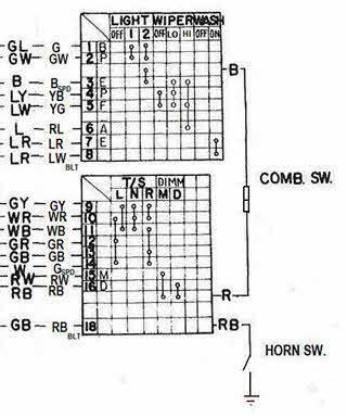
While I'm at it, here's my edit of the mini-schematic for the Combination Switch, corrected to reflect what I found in the actual layout of the wiring and contacts in the Combination Switch installed in my 4/70 car. I started with the mini-schematic that was part of large wiring diagram included with my car's Owners Manual ("20-Mar-1970 - 030300 - OM0E-0S30U2") and then made corrections... Note on the left side of the diagram that I have two columns of wiring colours: The left column indicates the colour of the wiring on the vehicle side of the Combo Switch connector. The right column indicates the colour of the wiring on the Switch side of the connector. 'SPD' = spade-type wiring connector 'BLT' = bullet-style wiring connector
-
Several years ago, I worked with your #2 schematic ("Datsun Factory Parts are fully warranted to give utmost satisfaction") and then added editing comments, using the wiring, connections, and devices in my car (unmolested 4/70 240Z) as my primary guide. See attachment #1. Back in 2015, CZCC member @EuroDat (Chas) did a beautiful job of creating a full-colour wiring schematic based on the specs for MY-1970 USA-Cda cars (see attachment #2). It addresses most of the issues that I identified in my own review. S30 Wiring Schematic - 70 240Z - B&W - 70 Owners Manual - Comments added for errors 7.pdf S30 Wiring Schematic - 70 240Z - Colour - Eurodat.pdf
-
Second that. Not an easy job: 1/3 educator, 1/3 keeper-of-order, 1/3 entertainer. Made all the more challenging in this modern era of cell phone and texting distractions.
-
That's going to be a great looking car when you get it done and out on the street. Keep up the good work.
-
I thought that Series 2 didn't start until VIN 046000. That said, this one seems to be a mix of S1 and S2... Series 1 equipment includes: Type A transmission, with matching console; brake m/cylinder has large reservoir at the front. Series 2 equipment includes: Storage bins built into rear floor; no air extractor vents in hatch panel; horizontal defroster grid in rear glass.
-
Agree. Those weld failure numbers appear to be premised on the joining of thick panels ('plate'), where lateral alignment of the joined edges isn't terribly critical. For thin automotive sheet metal, it will be difficult to achieve good panel alignment along the entire length of the seam. Even a brief segment with poor alignment will become the weak point that invites failure. There's also the potential for low-level burn-through, again resulting in weak point(s). Those published failure numbers are also premised on a steady separation load ('pull'). The weld in the shock tower will be taking variable loads (combination of spring load and shock absorber loads) that include the potential for big peaks if/when the spring bottoms out (the load curve will be high-amplitude and brief in duration, so quite demanding for the structure).
-
MZR offers three different models. The 'Sport Design' is simply a restored and upgraded/hot-rodded Z (albeit, done with industrial-grade processes and attention to detail). The exterior panels are OE and steel. The 'Evolution' and 'MZR 50th Anniversary' models use what MZR describes as "a lightweight carbon composite exoskeleton". It looks like this 'exoskeleton' consists of all of the external panels except for the roof (the rear quarter panels do not appear to be OE in shape). It looks like everything underneath is just a well-restored Z monocoque. The rear quarter panels and the rear-end panels would probably qualify as being 'bonded' to the steel structure. I suspect that the steel door shells and the steel hatch frame are retained, with carbon fibre outer panels bonded in place. If you were to purchase the steel versions of all of those exterior panels, it would cost ~ US$6,000 (plus shipping, duties, and taxes). In carbon fibre, they'd probably cost triple that amount (or more).
-
When assessing the dash wiring harness options, watch out for the Combination Switch. According to my records, the design was changed starting in Oct-1971 to accommodate Nissan's parallel decision to change the headlight switching strategy from ground-switched to positive-switched. Note also that the fuse block's wiring harness changed from from 'long pigtail' to 'short pigtail' at the end of Jan-1971. I expect that the dash wiring harness would need to have been changed to match. What transmission does Lily have - 'Type A'? or 'Type B'? p.s. Congrats on your daughter's wedding.
-
Were you using spot-weld bits (what brand?) or regular drill bits? Also, you say: "It shouldn’t have taken 2 hours, but it did……not for certain of the interior attachment points….. and they were non……." Please explain further.
-
I think maybe you're referring to Vogtland (Germany). If so, they're still very much in existence, although it appears that they may no longer offer a kit that applies specifically to the 240-260-280 Z's (they do offer kits for the 350 and 370 Z's, as well as the Altima and Sentra). The Vogtland kit that was referenced in CZCC for the 240-260-280 Z was PN 552-204. The free heights were 12.5" F / 11.5" R and the spring rates were 152 lb/in F / 170 lb/in R. They were constant-rate springs and the F and R rates fell about mid-way within the F and R rate spreads of the Eibach progressives (133 - 183 F / 154 - 212 R). For reference, the Tokico single-rate springs for the Z (NLA?) had free heights of 11.25" F / 12.0" R and springs rates of 185 F/ 200 R. If you contact Vogtland, you may discover that they still have some of the Z kits in inventory. p.s. Looking at your photos, I'm wondering whether the plastic sheathing on the lower part of the Eibachs might be contributing to the breakage problem by acting as a moisture trap and promoting corrosion. Lower part breaks first due to surface rust etching, upper part then gets overloaded and fails next. If you get another replacement set from TireRack, you might consider injecting some anticorrosion spray underneath the sheathing.
-
Yes. If you look more closely at my marked-up photo of the timing cover, you'll see two little pins -- one at ~ 2 o'clock and the other at ~ 8 o'clock. I think that their job is to hold the water pump firmly in (rotational) position relative to the timing cover, so that any pulses created by the fan belt drive don't, over time, destroy the integrity of the seal at the water pump gasket interface. While we're on the topic of the gasket, we should also discuss the use (or not) of a sealant in conjunction with the gasket itself. This topic has been discussed often on this site over the years. One respected member with a long career of racing his Z said that he had used Permatex High-Tack 'red' spray-on sealant for more than two decades and had never had problems with leaks. Another respected member said that he put the water pump and thermostat housing gaskets on dry and had never had a leak problem. A third respected member said that he used Permatex 'Aviation Gasket Sealer', but admitted that he considered the use (or non-use) of gasket sealant to be a matter of personal taste. In his words: "It's like antiseize. The factory never used it, but I do."
-
How did you determine 'top'... Was it the inertial* top? Or was it the geometric** top? * 'Inertial top' = the point where a carpenter's level would rest if levelled and placed on top of the tower circle. 'Inertial' is the same as 'plumb'. ** 'Geometric top' = the point where, when viewed from the front of the engine, a line drawn perpendicular to the top face of the engine block (head gasket surface) and going through the camshaft centre intersects the top of the tower circle. If you use the inertial top to gauge TDC with the cam lobes, you'll be off by 12 degrees. If you use the geometric top, you'll be ok. For an inline engine with normal architecture, all of the relationships between moving parts are based on an X-Y axis going through the centre of the crankshaft, where the Y axis drawn along the centreline of the cylinder bores (plumb 'vertical') and the X axis is perpendicular to the Y-axis (plumb 'horizontal'). When an inline engine is mounted in the vehicle with no cant angle, the X axis runs parallel to inertial/plumb horizontal and the Y axis runs parallel to inertial/plumb vertical. Picturing or calculating where all the parts sit when Cyl. 1 is at TDC is easy. When the engine is canted to one side, picturing or calculating where all the parts sit remains easy if you also cant the X-Y axis by a matching number of degrees. Having done so, the X-Y axis becomes an X'-Y' axis, and is 'relative' rather than 'inertial'. In other words, you have to adjust your frame of reference so that it's canted, or rotated, by the same amount as the engine block. If, on the other hand, you try keep your frame of reference aligned with 'plumb', things get messy. EZ-to-understand example of how this plays out: You're reassembling your L24 engine on an engine stand and have the engine rotated on the stand so that the cylinder bores are plumb vertical. You find TDC for Cyl 1 by rotating the crankshaft until the piston is at the top of its travel and the two cam lobes are pointed up.
-
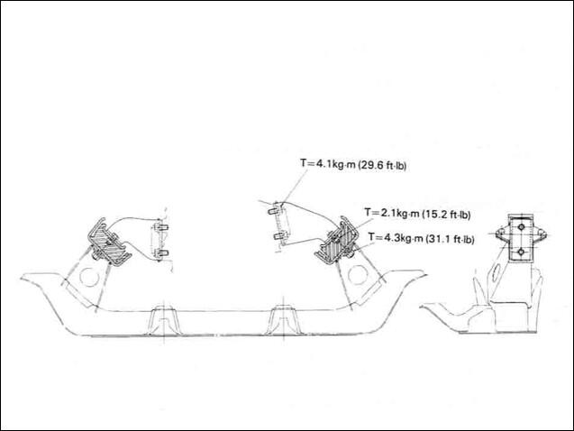
Thanks. In the absence of any other information, I had taken some measurements from a drawing that appears in the 1970 FSM (see below) and came up with 11.9 degrees... so I was close. Good to have this confirmation.
-
We all know that the Z's engine is canted off vertical. However, I've been unable to find any diagrams or tech info that indicates, definitively, what the cant angle is. Does anyone know the engine's cant angle? An, if so, what's your source?
-
An the compressed air was free!
-
Somewhere on this site, there's a video posted by @Patcon where he shows his technique for starting an L24 engine that (IIRC) had the carburetors completely removed. That may give some ideas for what you did wrong (or forgot to do). FWIW, it doesn't take much of a shot of starter fluid (spray) to light off an engine. You may have created a totally over-rich condition by being too heavy-handed with the spray bottle. That said, have you taken the steps to ensure that you've got a spark at each of the cylinders? This isn't hard to do. "Electrics first. Fuel second".
-
@AZ-240z Depending of course on whether you have the time and interest, a photo essay of the details of your car's engine compartment would be a great topic for a separate thread (maybe in the 'Resources' section?) It would certainly be a nice reference piece for other restorers.
-
According to my notes, the use of the 140psi gauge ended as of "1/71", somewhere around VIN 020000. This implies that the installation of the 90psi gauge began in Feb-1971. FWIW, the lowest and highest VIN's that I've seen for a 1/71 Z are, respectively, 018482 and 020500. That VIN range should be considered approximate (my VIN database is by no means complete), but the high-end number (which would align with end-of-month builds for January) is ~ 5000 units later than Lily's VIN of 014938 (11/70?) and coincides with a time when Nissan's production rate for the Z was ~ 2500 units/month. There were a lot other changes made to the car's detail design and equipment at the same time, but the "1/71" change date might have been a bit fluid from one item to another so that Nissan could use up existing inventory for the various affected parts. However, it seems unlikely that any of these changes would have pre-dated "1/71".


