


Everything posted by zKars
-
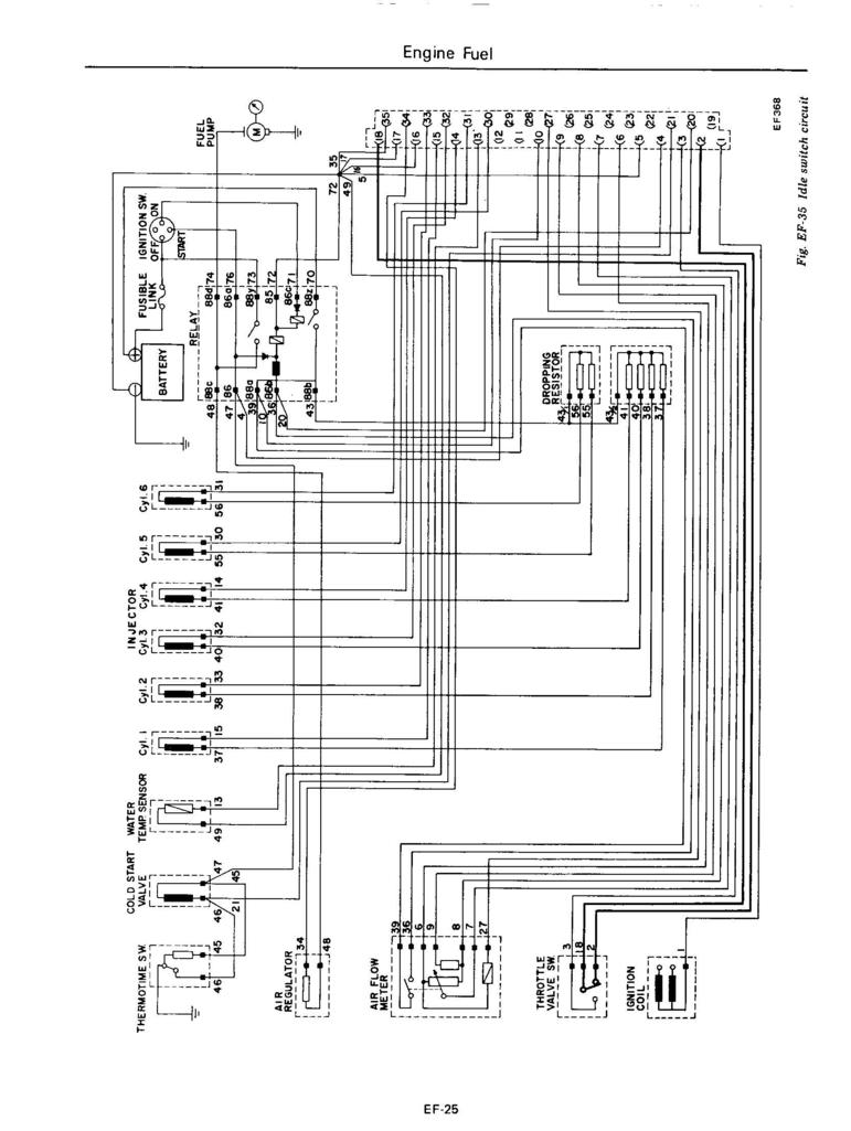
Hey Ed, glad to hear you're still thinking Z cars and expanding the applications. The 74-78 Z's with FI all use a single wire from the coil "-" terminal to the ECU pin 1 as the ignition trigger, so technically as long as the coil output is "the same", then using an 123 dizzy shouldn't cause an issue. Practice may differ from threory as usual, but I'll bet it will be okay.
-
I HATE brake nuts. Of all the threads I've used brake line nuts cause the most grief. Alignment is key. Loosen the other end of the lines where they going into the distribution block below the master to get the sloe you need. And or remove the bolt that attaches that block to the engine bay so it gives you room to move there too. Do NOT remove them or you will have the same problem. Maybe remove them, bend the master end a touch, then put it back on the dist. block end and try again. I say put the master back on the booster adn tighten it down, since its too long already, being loose makes the alignment even worse. Be careful with any lubricants, just put the tiniest dab on the threads as Jim suggested, don't get any where you touch it. You can't afford any loss of torque or control. And don't get any on the mating /sealing surface. Good luck. Try taping your fingers with something high friction before trying again or at least a latex/nitrile glove.
-
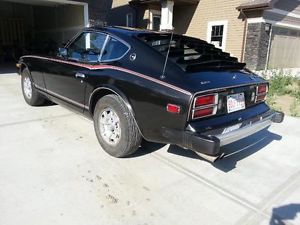
Not mine and don't know the seller. Just spotted it this AM. Looks pretty darn good and price is very very reasonable too @ $6500 CDN (about $1.25 USD...) 1978 Datsun 280Z - Excellent Condition & Nothing to Fix | classic cars | Edmonton | Kijiji

-
A tough and common problem. The solution many choose is to put a right hand end on and change the tie rod to a right one as well. Both sides are exactly the same except for the thread. Just have to find an alignment person who can handle moving his wrench in two different directions to set the toe in.
-
And lets not forget bartsscooterservice for starting this thread. I look forward to some day coming to NL, rent a scooter and having you service it.
-
Just saw this. If its the two I think, they are 12x1.25 bolts. They connect through the steering arm They are two different lengths, and have a quite a specific shoulder diameter, though that is not all that important. They are 10.9 grade. Hope that helps.
-
It seems I may have convinced the seller that I am worthy of relieving him of his Datsun burden.
-
Great article. Thanks for posting it. And I'm impressed to see such a clear and clever "Not even Maybe" statement about the Geortz issue in the media.
-
Business first. The Z in the ebay ad is a Dec 70 build, who cares about the VIN now..... Still going to go get it (hopefully) soon. ZCON prep and other commitments are not helping the cause much at the moment. Neither is my poor choice of manifold gaskets.... ;( Now, parts wise: NorthernZ, I have a console for you one way or the other. At least the console body itself for sure, and I have certain other components. Pretty sure I don't have a complete Ashtray/door though. Big surprise. 240dwk, the 510 is waiting for paint over the summer. Re-assembly will be over the coming winter. Hope to have it for Kelowna next May long. Somewhere I have a broken ashtray lid that likely has that chrome ring on it. Will find and forward.
-
I've sent him a note to get the VIN. See what he says. Parts anyone?
-
I hear ya Steve, its not just the linkage, its just making the overall problem seem worse. Just had to get that off my chest. Water is one of the products of combustion, what you're seeing is not from ambient humidity, or heaven's forbid, cooling system sourced. Not sure what combustion conditions make more or less water, but it sounds like you may have found a cure for California's drought! Collect that water and send it west! Hard to imagine many failure modes that cause a too-rich condition. plugging, air leaks etc tend to make things too lean. Spilling fuel due to too high pressure is all both barrel related though. Hey, you haven't lost any solder out of your bleed pipe hole filling effort have you?et How about damage to the inner venturi where the main jet fuel comes out? scrapping the barrel here, how about the "jet block" that the main jet tubes mount in, its a separate thing, and it screws into the main housing, maybe the screws are loose? The screws that hold it in place are accessible from the accel pump cover. Maybe getting fuel in where it doesn't belong? Loose/missing nuts/screws that hold the main venturi and choke venturi in place from the outside? Did you replace one of your throttle linkage mounting bolts with a longer one and do a number (crack it, break it, bend it) on the venturi just inside?
-
Ah the old sloppy linkage problem. So many joints, so many places for a little bit of slop and bind and twist to add up to trouble. Who's idea was multiple carbs anyway? So beautiful and so much trouble. So help me if I ever find him, I'll lock him up and make his food only accessible when a complex linkage of bars, pulleys, turnbuckles and wires are working JUST so. Give him a big flat blade worn our screwdriver as his only tool to adjust it. Couple days here and there of working "ok", but mostly months on end of coughing and spitting stink and bad mileage... Me thinks he will starve very slowly.. Bwaaahahahahahahahahahahaa.. Maybe its time for a matched motor servo on each carb shaft and a drive by wire pedal....
-
Dinner and a show? Well, maybe for some people, but if you're really a car guy, then do this! RACING SCHOOL, Exotics racing school is the ultimate driving experience at Las Vegas Speedway with Ferrari, Lamborghini and Porsche. or at least this! http://www.shelbyamerican.com And if you must do the show thing, go see The Beatles "Love" cirque show at the Mirage. It's almost done it's 10 year run. Been three times.....
-
So suspend car from rafters upside down, then inset bolts into manifold upward and tighten? So no-one's heard of the peanut butter trick? Thick enough to hold the bits together while you insert them, then it melts off when you run the engine and you get the joyous odor of hot peanut butter cookies while it melts off. Oh ya, and "A little dab will do ya'!"
-
These guys have nice CAD plated SEMS metric bolts. Search for "SEMS M5" or "SEMS M6" to see what they have. M5 - 0.8 x 30mm Phillips Hex Head SEMS Screw, Class 8.8 Is the lock and flat washer a show stopper?
-
Very nice! Restoring the rest of it will be a great experience. One place that I remember that has the spherical ball joint tie rod ends is here. https://technotoytuning.com/nissan/240z/outer-tie-rods-datsun-240z-260z-and-280z
-
Assuming you have one of those new fangled holley carb things on there, you can find ignition switched +12 at the voltage regulator on the BW wire. Might be an ignition hot pin on the wiper pin? You can use the coil + if you use it to trigger a separate relay that takes main power from the battery I suppose. Can't think of anything else that ignition +12 under the hood. Even the inspection light wire is on all the time.
-
What did I tell ya?
-
Ryant67, yes, it normal. Throttle blades snap shot, no air flow = no fuel, = high AFR. The back fire is something else, ie residual fuel in the system getting ignited by elevated temps in the exhaust. Definite sign of being too rich most of the time. I used to get that engine braking down a hill. Sounds all racy and stuff, like I have a bad arse motor. Even got little flames some times. People point and stare, and I'm sure they are thinkin' "that guy is cool with that fast car"... That is what they were thinking wasn't it? Right? Don't worry about spend too much on jets. I'll relieve you of your burden and re-line your pockets when you're done jetting.
-
While we're at it, thought I'd share another Mikuni tuning observation. When the tuning was "slightly too lean" like 15-16 idle, 15ish putsing around town and on cruise, 15-16 at WOT, the car never sounded so smooth, quiet, never idled better, it was a dream for my old kinda nasty cammed stroker. This was with 57.5 pilots, and 150 mains. Trouble was, it wasn't just the noise and harnessness that was gone, so was the power. The WOT power was slightly hesitant and bucky, just like what you're told when its too lean. No strong pull, obvious faltering. Around town felt "ok" bit it lacked the punch it had before. But the smoothness and quieter exhaust note were intoxicating in some way. I guess I could use this baseline for days when we're cruising on long trips and there are no "fun" parts where you want power, just smoothness and fuel economy. Hardly convenient, and no dang good at all when do get a "look" from some hi-brow in a $50 bazzillion dollar hot rod ... or an actual curve appears on the road ahead. Dang carbs, why can't I hide some injectors in there somewhere.... So I'm back to 62.5 pilots and 160 mains (see edit above) with carefully tweaked idle screws to get the leanest idle I can stand. Its brasher again, noiser, rougher, but it runs like the perverbial violated primate.... WOT is a total hoot. Stomp it anytime from 2K and it just pulls. AFR''s are 12-13ish at WOT. Another observation after careful inspection. The first transition hole is JUST covered by the blades when fully closed, at least on my carbs. Virtually ANY amount of opening exposes that first hole almost immediately. Pretty tough (dare I say impossible?) to get that supposed ideal position where NO transition holes are exposed, just running on ilde screw port fuel, but the blades open enough so that it can idle. Now my blades are hardly pristine and un-touched, my old Q types have seen many miles. They're clean, but the blades don't close all very evenly. A strong light shone from front to back with them in your hand shows a variable amount of light sneaking around tortured blades from barrel to barrel. Still this idea that "no transition holes until you actually USE the gas pedal" is pretty darn hard to attain. This explains the option to plug up that first transition hole that I've read about. I don't have a throttle-on stumble, the accel pump takes care of that, but if the pilots are too lean, it starts to show up, as you have to open the screw too far and you steal all the idle fuel before it gets to come out the transition holes. What a crazy balancing act.... Maybe if I have a air bypass valve to the vacuum log to adjust idle. hmmm, more hoses, valves and tubes... It lets more air in, but its dry, so have to increase the pilots..... here we go again!
-
Well we know its been painted then with likely rust repair. There were no OEM black S30's other than 78 black pearl's, were there? But dang it's near free at $5K. Bet we hear its been sold by 5:00pm East
-
Well getting the same jets in all of them is a good first step. Can't imagine trying to get that thing in balance the way it is. Time to call Todd.... I have 62.5 pilots, 160 main and 200 airs 34mm chokes and idle screws at 1.5ish in my 44's on a 3.1 stroker EDIT : Sorry, the original statement above said. 150 main was actually 160. 150 was an earlier iteration.John, wise and experienced thoughts indeed. No surprise that we are overthinking this. Buy the best grease you can find, pack your bearings properly, throw some in the housing if you feel like it, and forget it about for 10 years. Yet I can almost guarantee you that at least three of "us" will now go and mock up an experiment with a rear axle housing and freshly packed bearings, where a propane torch and an electric motor are involved. They will measure 3D grease displacement at varying temperatures and centrifigal force values, and will plot the results in an excel spreadsheet. Only they will find that no matter what they do, the grease just stays in the bearings.... like its designed to do....Granny, you bring up a couple of interesting areas for a further discussion! In the article I found, he mentioned a few words about how wheel bearing grease works. It has two parts, a carrier, the heavy thick stuff, and the actual oil that is extracted from the thick stuff that fills and lubricates the bearings.The balancing act is having enough volume of "grease" (both parts) to keep the lube action going for it lifetime. Eventually the grease breaks down and goes hard and waxy. I've seen in lots of old bearings. Hopefully this happens at the end of the service life (150000-200000 miles) All the stock bearings I've seen only have one integral seal on the outside of the inner bearing, all of the other three bearing faces are open to the housing guts. This implies you need grease everywhere in the housing to keep these supplied. I'm a bit worried about grease life with having bearings that are sealed on all four sides that have a much reduced volume to use. It also makes me think someone before you replaced those bearings. This all assumes that the total grease in the bearings and in the axle housing warms up and thins out enough so that there isa net flow of grease throughout the space over time. Otherwise what is the point of having (some) grease in the axle cavity front or rear if only the grease in the bearings themselves is doing anything? It hard to find information on "axle grease flow dynamics"....

Important Information
By using this site, you agree to our Privacy Policy and Guidelines. We have placed cookies on your device to help make this website better. You can adjust your cookie settings, otherwise we'll assume you're okay to continue.