.JPG.cfcada9cf1c1b502df3f5f2f2ca3ff36.JPG)

SteveJ
Community Member
-
Joined
-
Last visited
Everything posted by SteveJ
-
So what is your budget for tires? That will drive most of the selection for you.
-
By the way, I can install the latch at my house. Is the striker plate in good shape?
-
It's the same 70-76. The 77 had the new design. What size are the tires?
-
-
I am just curious. Why did you go with an electric fuel pump? Did you use an oil pressure switch or inertia switch to cut off power in case of an accident? You can find the fuel pressure range needed in the EF section of the FSM. Before you buy a regulator, you might try installing a fuel pressure gauge. You can get a fluid filled gauge from Amazon at a reasonable price: https://www.amazon.com/gp/product/B000CIH38M You'll also need an adapter for the gauge. This is one for regular fuel line: https://www.amazon.com/gp/product/B00093CL3M After that, if you need a FPR, and I doubt you will, here is one. You'll need 3/8 NPT to 5/16 barbed fittings, too. I also recommend getting fuel-resistant teflon tape. https://www.amazon.com/gp/product/B00029JC6M
-
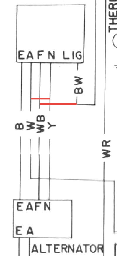
There are wires on the engine harness connection for the voltage regulator that need to be jumpered out. Please read this and tell us if you modified your wiring accordingly. http://www.zhome.com/ZCMnL/tech/280Alt.html

-
Okay, but there is more to it than just that plug. What else did you do?
-
What about the jumpers needed at the connection for the voltage regulator? Also, what do you mean by you followed the MSA wiring? They sell products, and I don't recall seeing tech tips on their site.
-
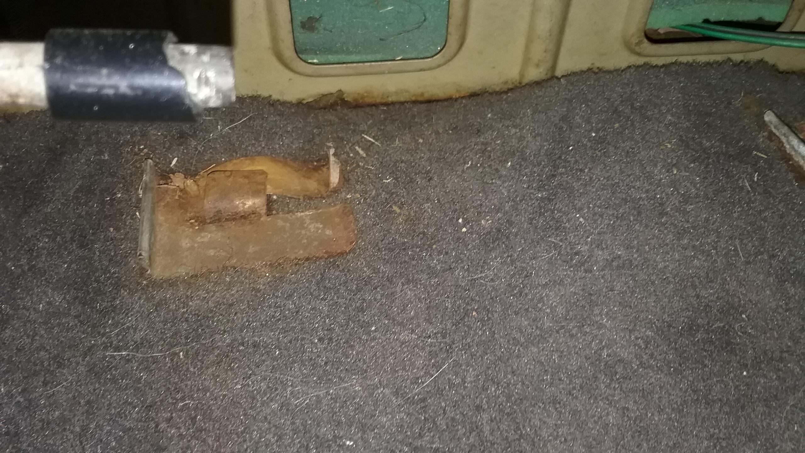
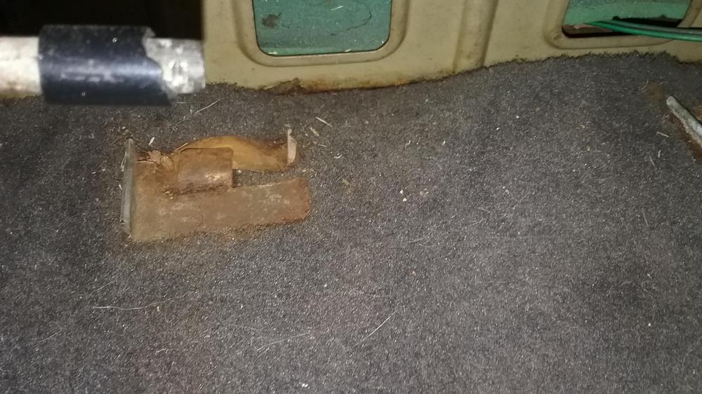
Here is a clip in my car
-
If my feeble memory works, I'll take photos tonight.
-
Those are probably to hold the carpet in place. I have them in my 260Z.
-
@gwri8 and @Redwing are west of Elijay. For BBQ in Elijay, look up Walker's Fried Pies and BBQ. My wife and I liked that place.
-
@Zed Head likes to poke fun at me about this, but I'm going with my standard line of posting. We need more details. What DIY? There is more than one. Can you post a link to it? Can you post quality photos of your wiring modifications, including the diode with polarity shown? Can you provide the part number of the diode you used? There is some issue with sensing battery voltage. The additional information may clear it up.
-
Where in Georgia are you planning on visiting? Fellow Z people are always welcome to drop by to visit.
-
You're welcome.
-
Sims Radiator (http://www.simsradiator.com/lawrenceville) is who Tim McGovern usually recommends.
-
I think @Rickers is referring to the rear panel/valance. I found a couple of the lower valance on ebay: https://www.ebay.com/sch/i.html?_from=R40&_trksid=p2386202.m570.l1313.TR0.TRC0.H0.XDatsun+240Z+rear+valance.TRS0&_nkw=Datsun+240Z+rear+valance&_sacat=0 I couldn't find a whole rear panel.
-
With not knowing much about cars, the best thing you can do is start reading. Read about what a stock 240Z is and what it takes to turbocharge an engine. It is not a simple task to "slap a turbo on" an engine that was not designed by the factory to be turbocharged. Watch some of the videos that come in the last link I provided. You'll see those cars have a lot of modifications. Also, when you start adding power, it's a good way to find out what else isn't working well. You're starting out with a car that is about 45 years old. Many parts are wearing out, and you want to introduce additional stress on those old parts. We're talking about U-joints, half shafts, bearings, differential gears, transmission gears, bushings, tie rods, ball joints, and mounting locations for suspension components, just to name a few. If you truly want to own an old Datsun you may want to do this: Start looking at parts prices. You can find many parts vendors in the links on my blog: http://fiddlingwithzcars.wordpress.com. That will start to give you an idea of what you may need to spend just to get your car in shape. Keep in mind that many parts are no longer available (NLA). Also, this will not include labor. This can help you set a budget. Buy the best body car you can find. Replacing a drivetrain is a LOT easier than making lasting repairs to a rustbucket. You don't want to go too cheap here. Find someone who knows about cars to go shopping with you and have that person be ready to tell you to move on if the car isn't worth it. These cars are prone to rusting, so expect to pay a fair amount to get a solid car. Read and take notes. There is a lot of good information online and in books. Ask questions to clarify issues or to get help to point you in the right direction. People will be more receptive to providing meaningful and detailed answers when you ask meaningful and detailed questions.
-
You might gain some insight from reading threads from this search: https://www.google.com/search?q=turbo+2.4+240Z+site:www.zcar.com&sa=X&ved=0ahUKEwjRkon4zLrXAhUr1oMKHQaTDA8QrQIIMigEMAA Also it's good to read what you can find on hybridz: https://www.google.com/search?ei=ShEJWsKgCIWDjwSmoLSgCg&q=turbo+2.4+240Z+site%3Ahybridz.org&oq=turbo+2.4+240Z+site%3Ahybridz.org&gs_l=psy-ab.3...362464.366166.0.366323.13.13.0.0.0.0.253.1327.10j2j1.13.0....0...1.1.64.psy-ab..0.0.0....0._howOQosH24 From what I saw on those threads, be prepared to do a head swap to lower compression before you consider boosting. Also, do you have experience with working on boosted engines? What cars/engines? Are you thinking of keeping the SU carburetors? Have you done any research besides posting your question here? One more Google search for your reading and watching pleasure: https://www.google.com/search?q=turbo+tom+datsun&oq=turbo+tom+datsun&aqs=chrome..69i57.3808j0j7&sourceid=chrome&ie=UTF-8
-
Yes, our monitoring indicates that you are.
-
Honestly, it's an assumption on my part since I'm guessing he asked you the same thing.
-
He's getting his Christmas card list together.
-
@wil84911 You could bring your car down for ZCON next year, and we could put it up on my lift.
-
It's quite likely the turn signal switch. If you are mechanically inclined: https://fiddlingwithzcars.wordpress.com/2012/12/04/turn-signal-repair/
-
https://fiddlingwithzcars.wordpress.com/2013/01/20/hazard-switch-brake-light-turn-signal-circuit-analysis/