HusseinHolland
Community Member
-
Joined
-
Last visited
Everything posted by HusseinHolland
-
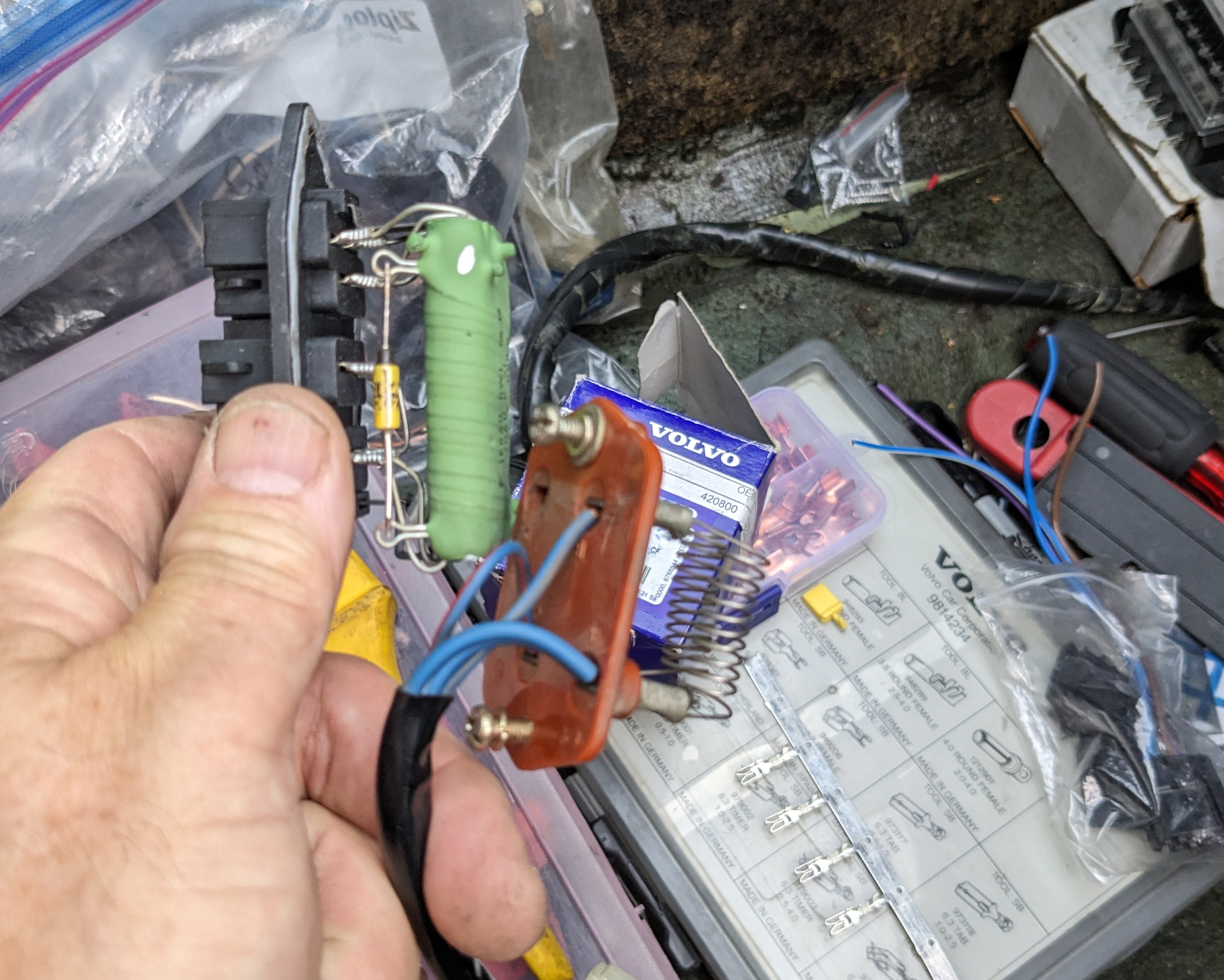
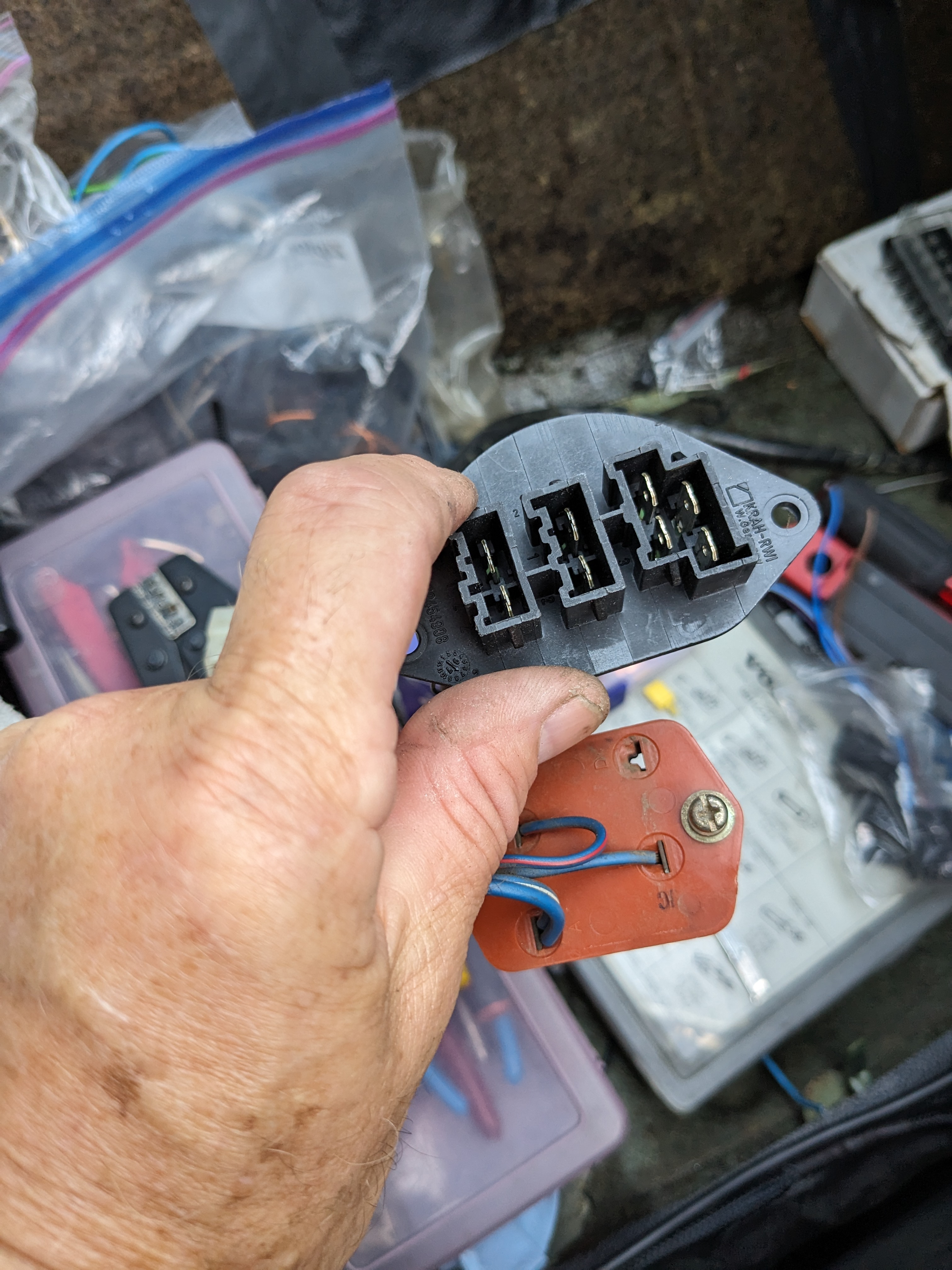
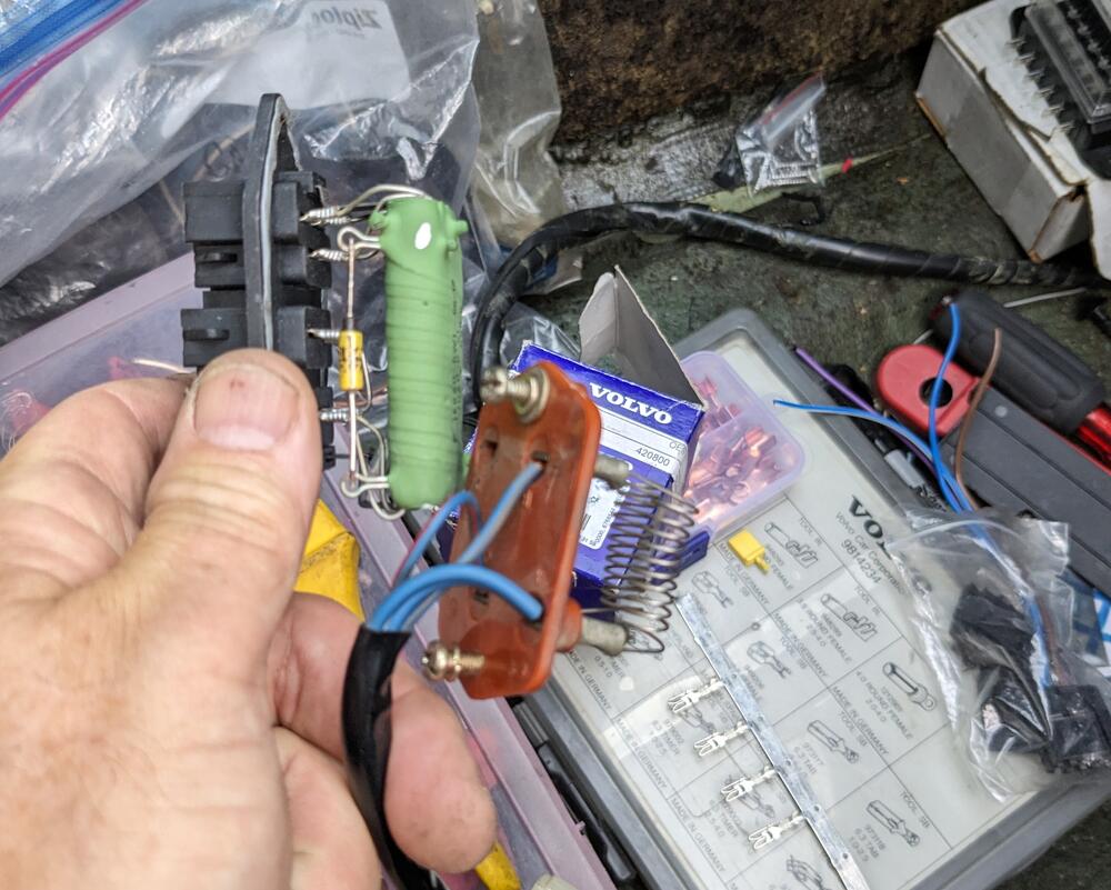
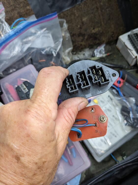
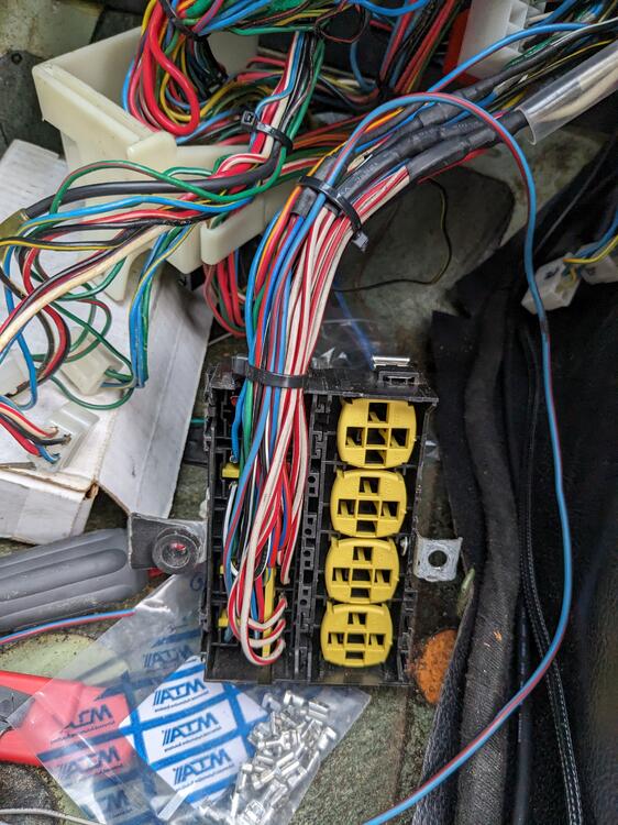
Adding switched power to one relay to be used to switch the blower fan on low (1) speed when AC is engaged Spliced the main battery feeds to run to the ancillary power strip before going to the new fusebox Going to use a Volvo fan speed resistor in place of the 3 speed non AC setup I have. I'll modify the blower casing to fit it. Opening only has to be altered slightly. Difference is this mounts from the outside, vs the stock resistor being bolted on the inside. Top 4 pins are speeds 1-4 next 2 pins are full speed, bottom 2 are output to blower motor
-
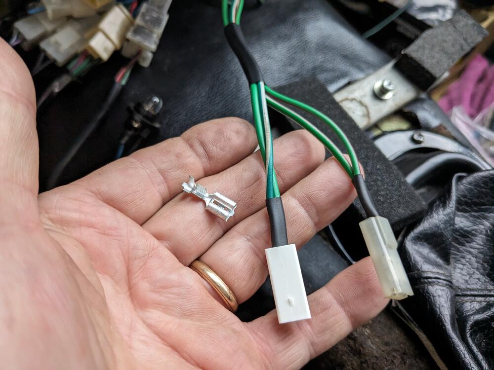
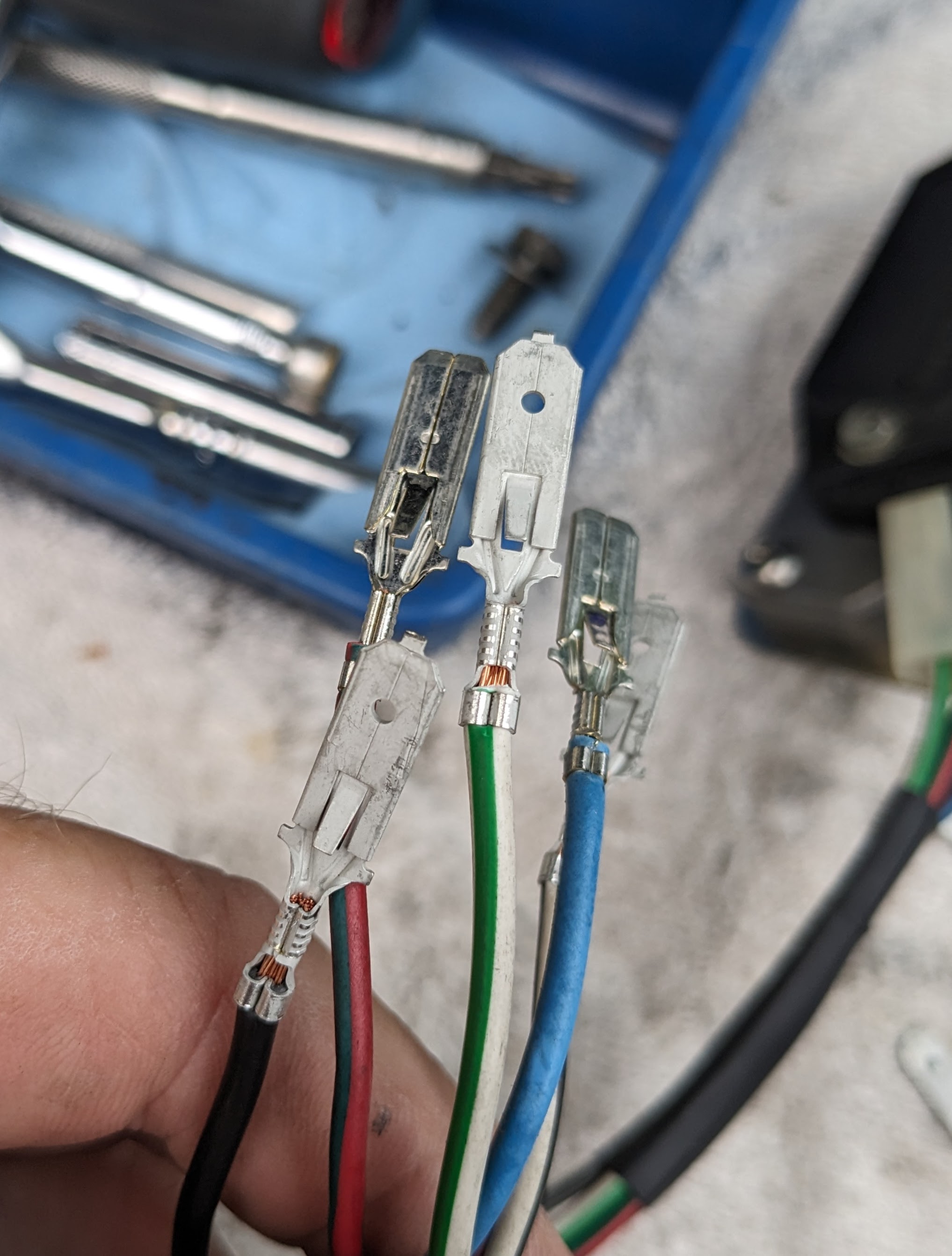
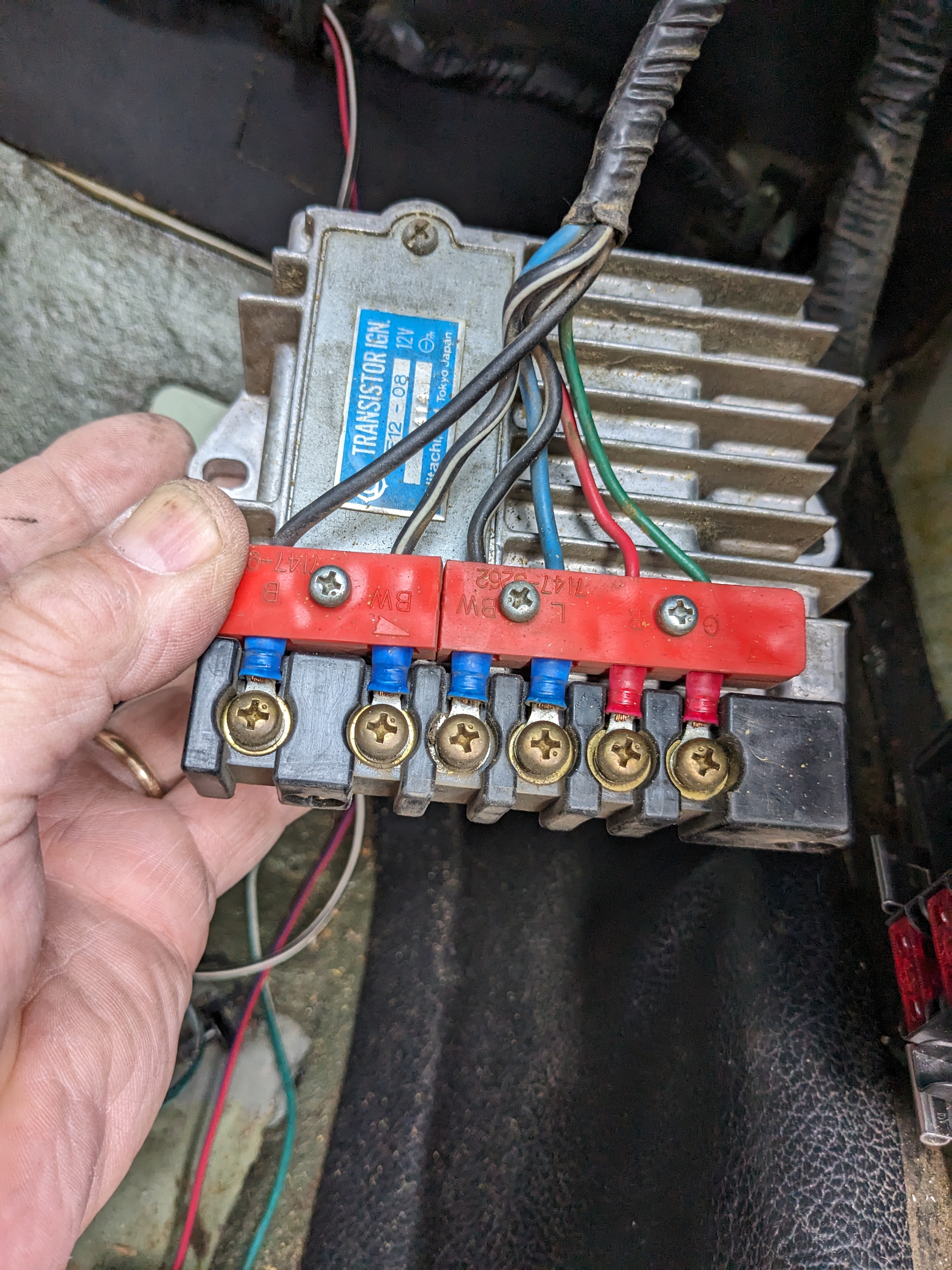
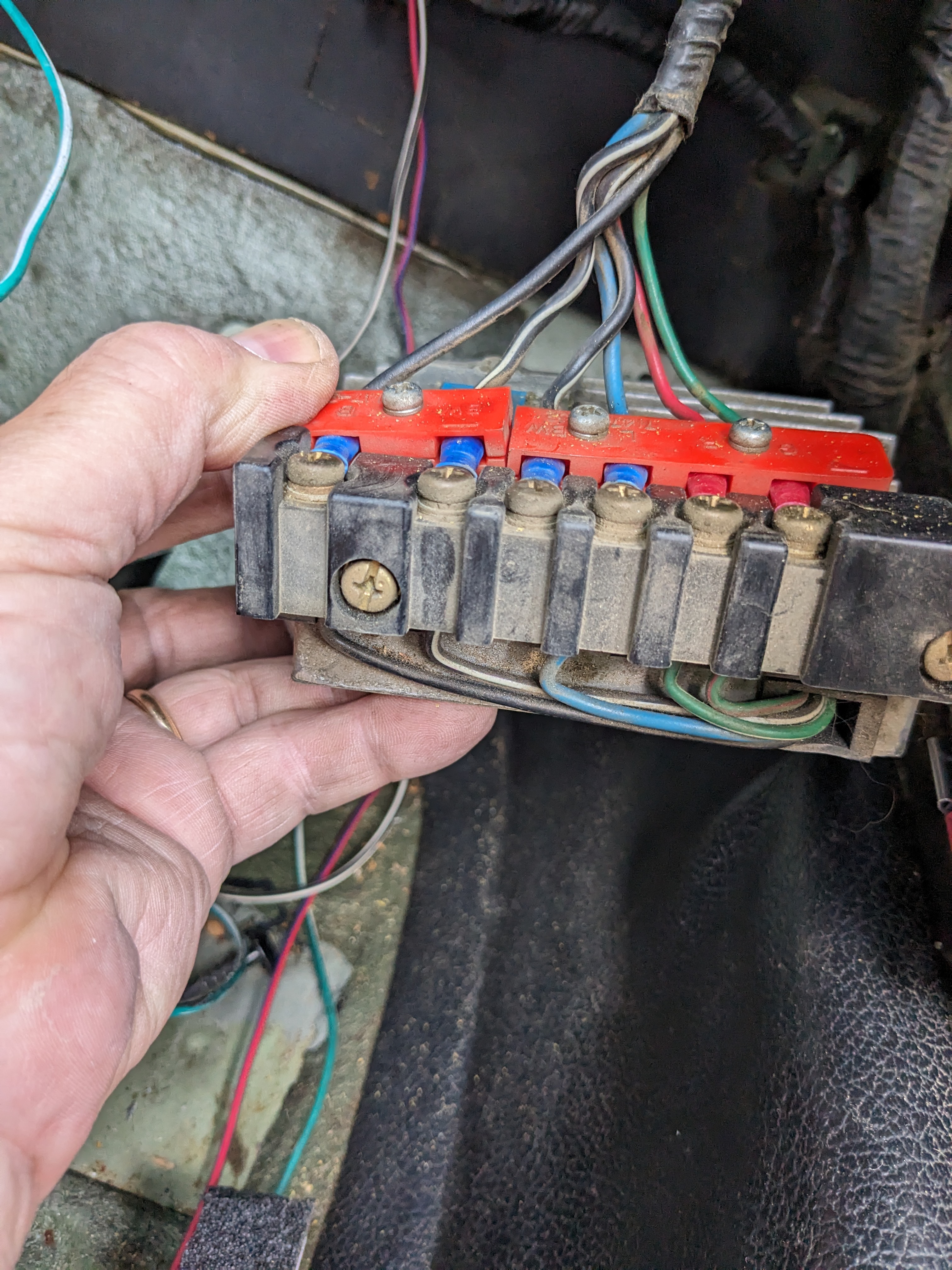
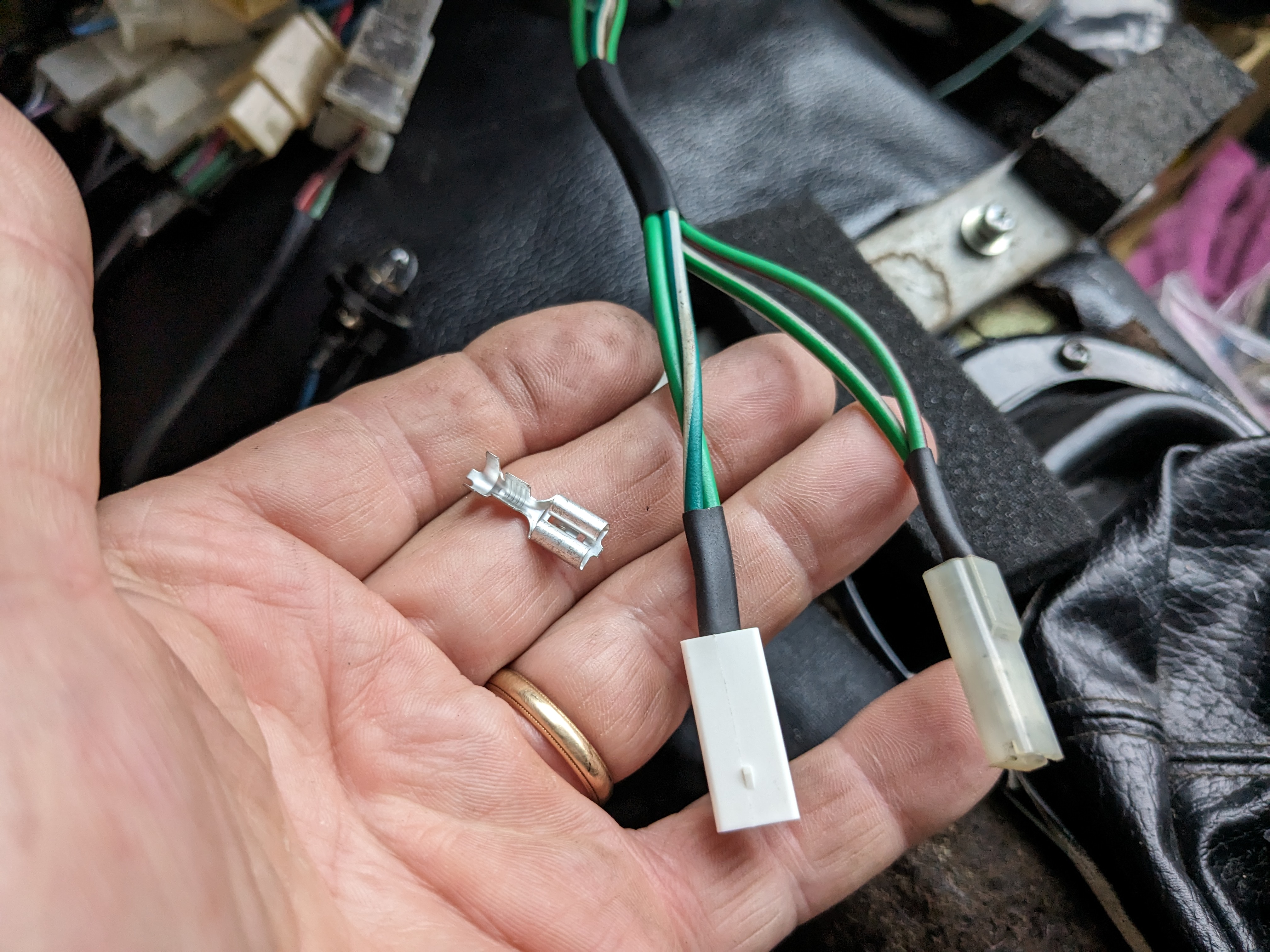
Hopefully I have no actual issues with the module in operation, this is all just about ensuring the wiring is accurate. I wired the sub harness for the HEI module today 6.3mm spades for the connection to the factory harness I made a bridge on the harness side, to connect both Blk-Wh together
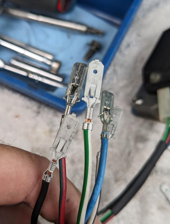
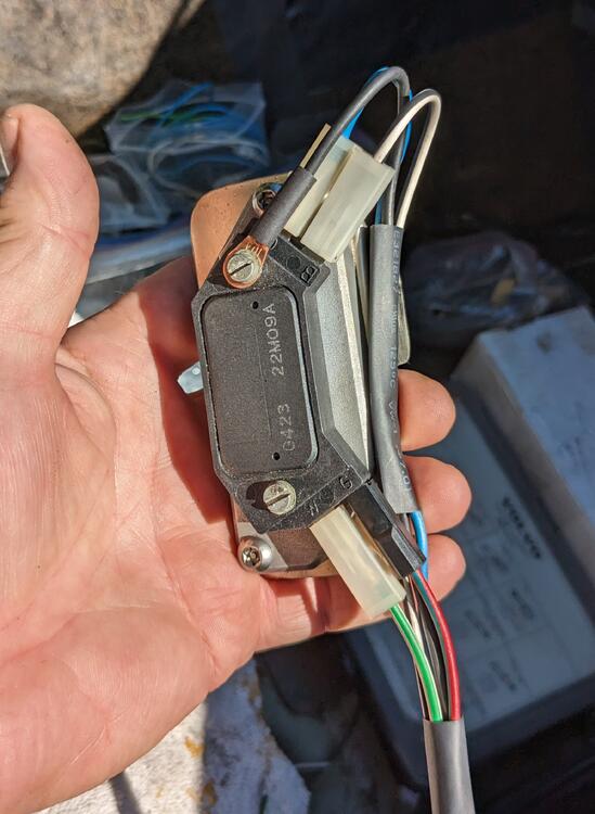
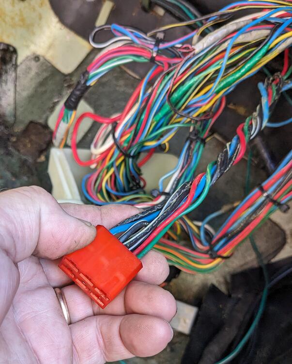
-
Thanks for the confirmation, EuroDat. I thought about moving it the bay, much less wiring to worry about. Playing with placing the HEI & heat sink, I couldn't find a nice flat spot to locate it, except under the triangle steel web in the left corner near the AFM. Even though I don't plan on driving the car in the wet, the fact that the connections at the HEI are unsealed is enough for me to stick with placing it in the cabin 😁
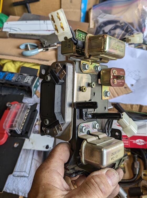
-
Thanks for your experience, Paul. I had noted in EuroDat's directions that he bypassed the ballast. Since I'm using a Volvo 12v coil that didn't use the ballast to begin with, I am going to do as he did & bridge the ballast terminals, to keep the connections tidy.
-
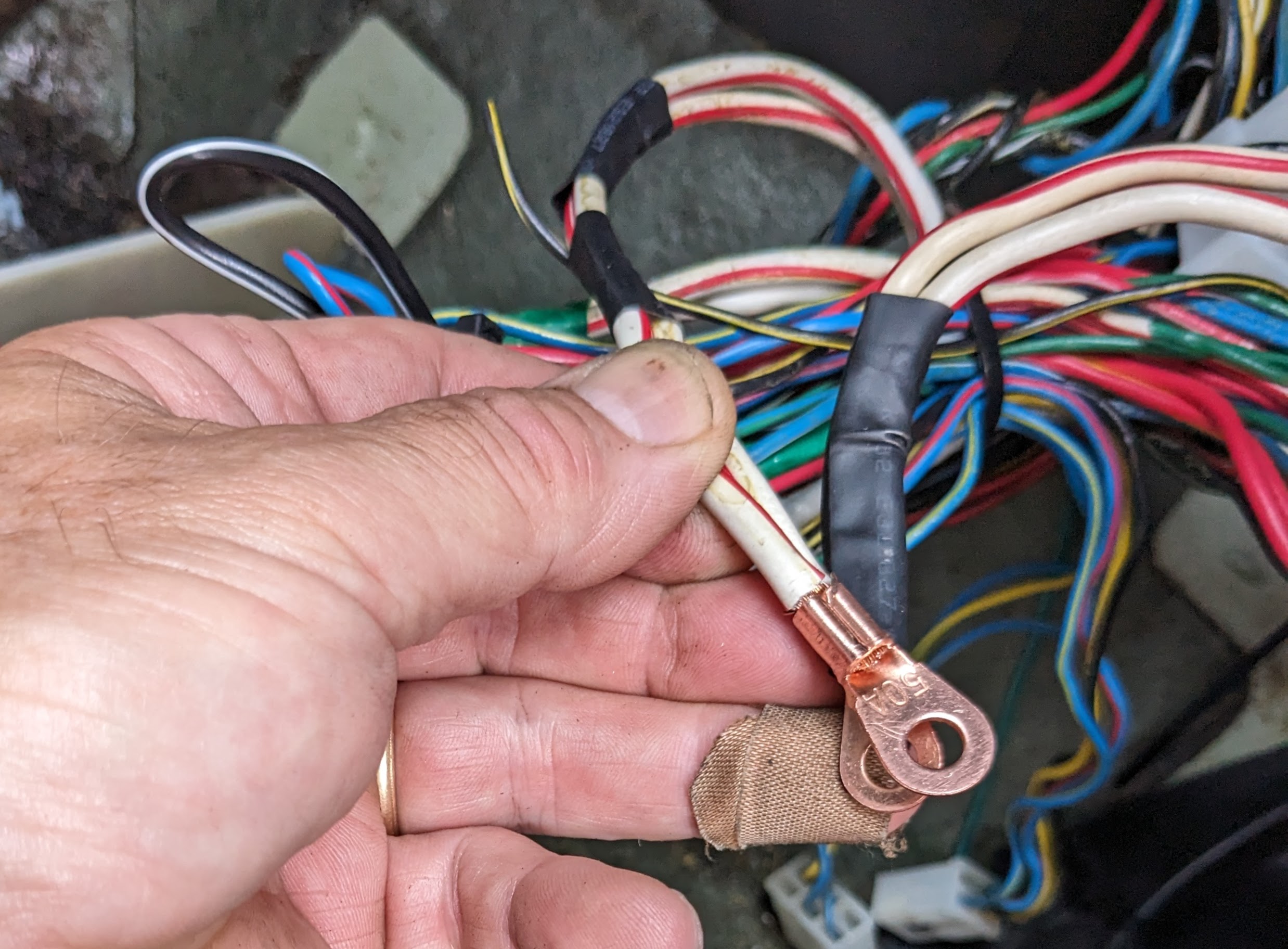
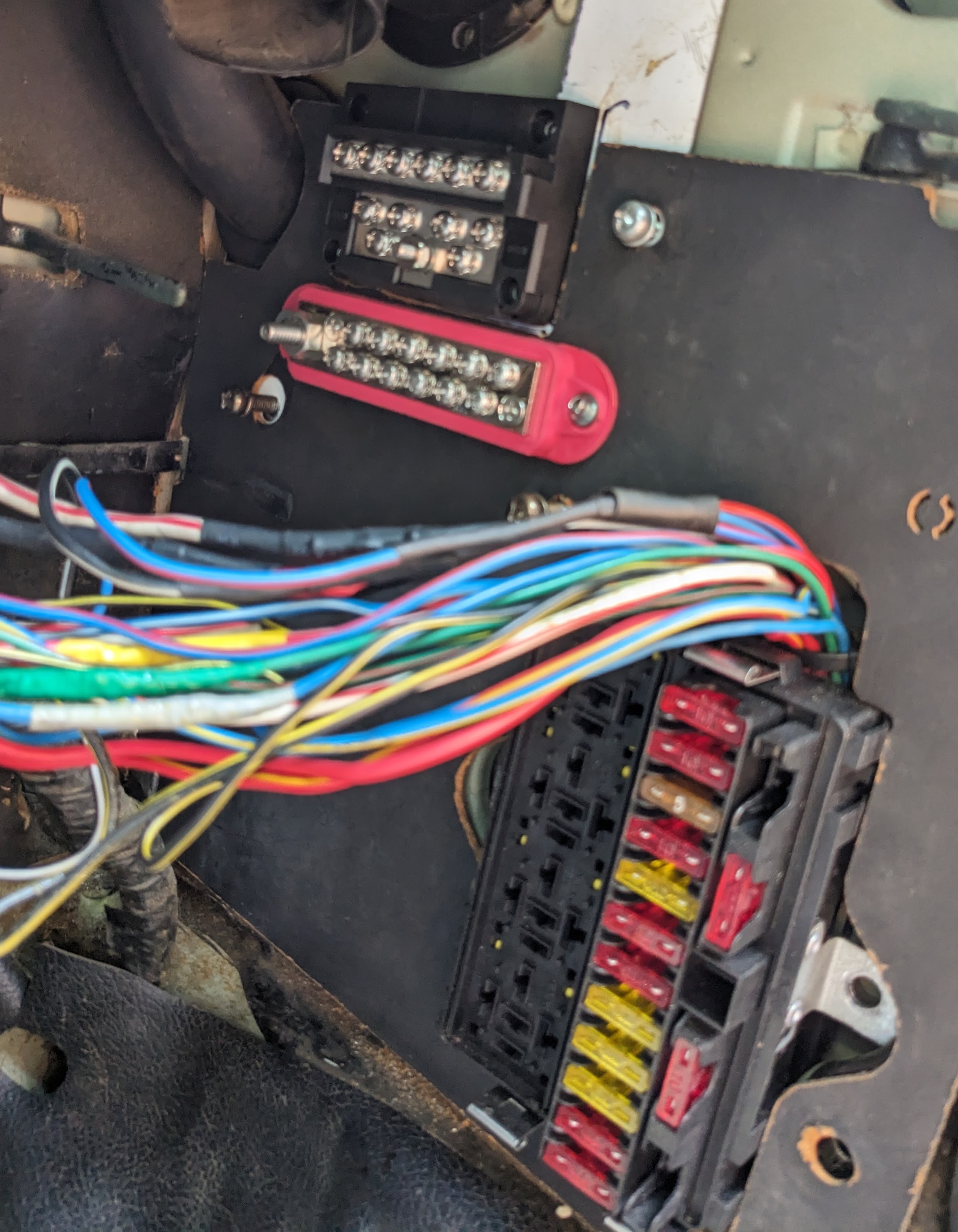
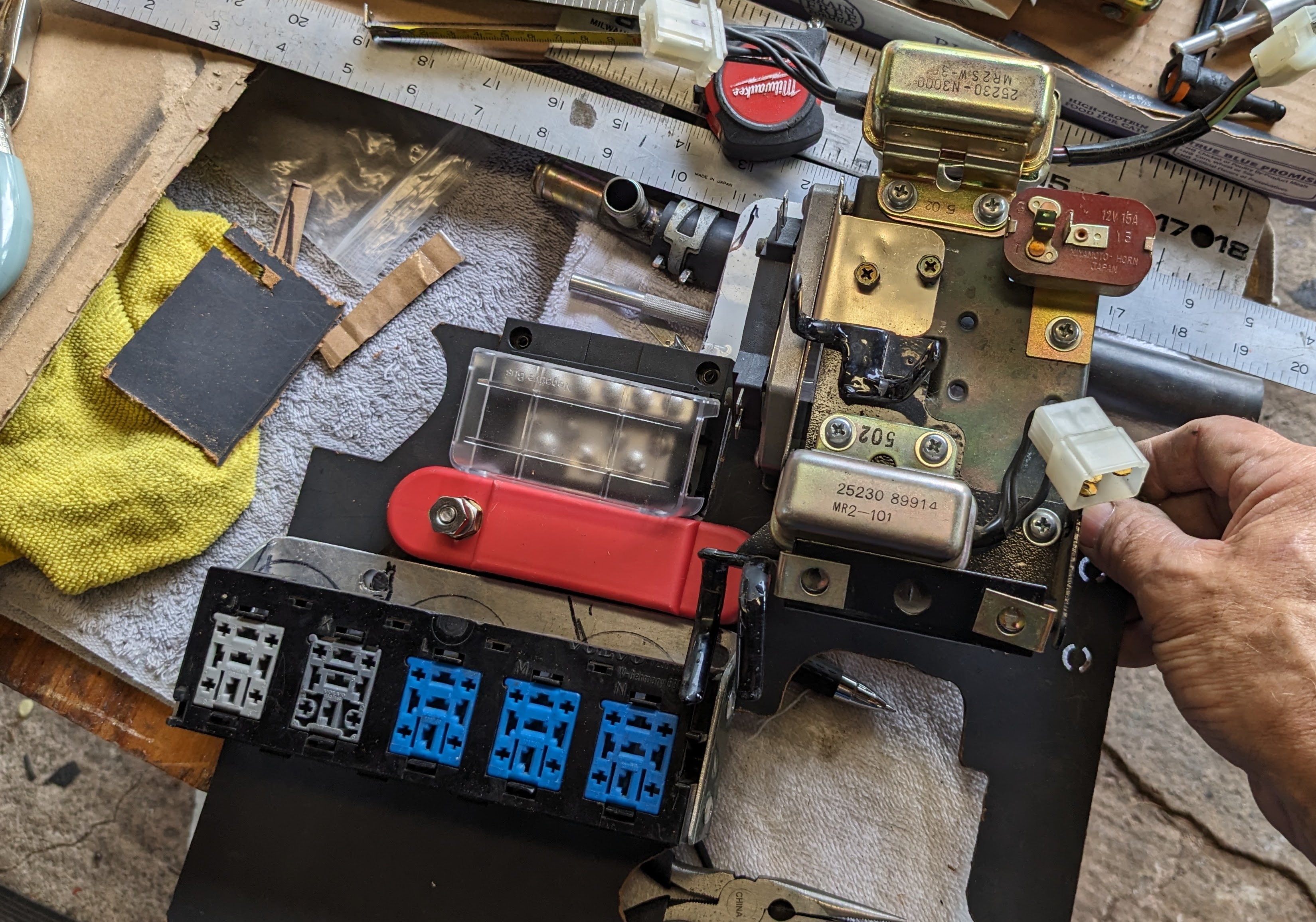
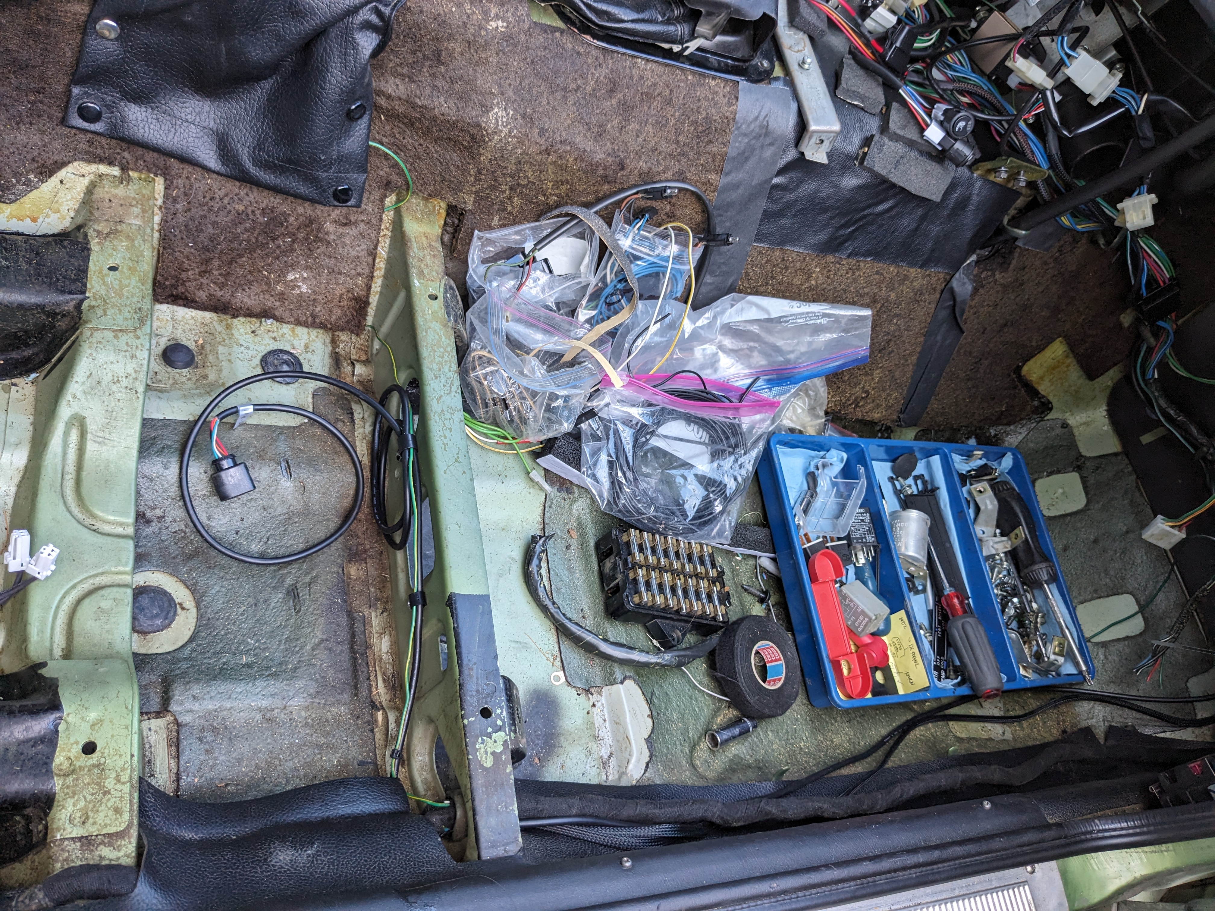
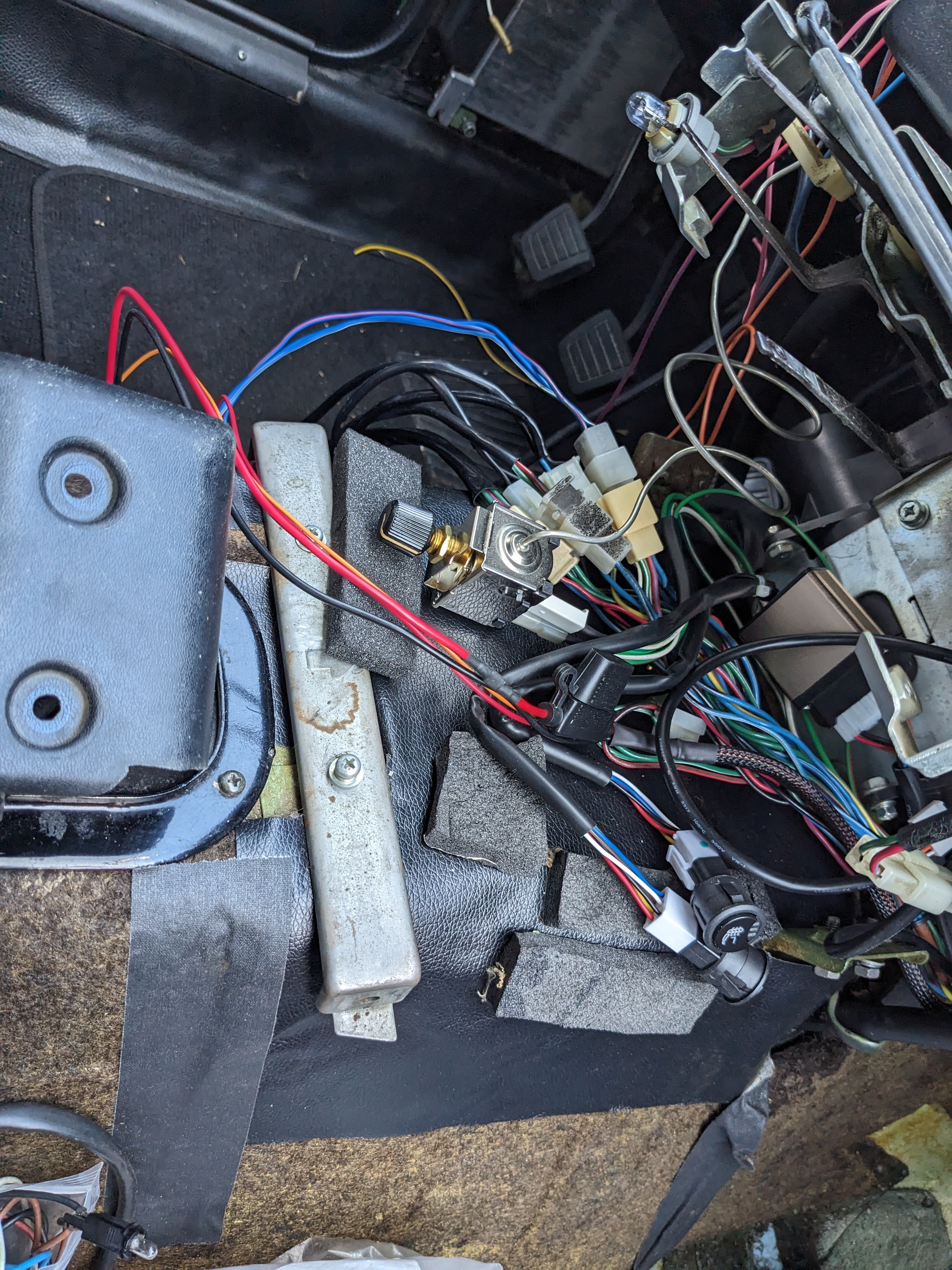
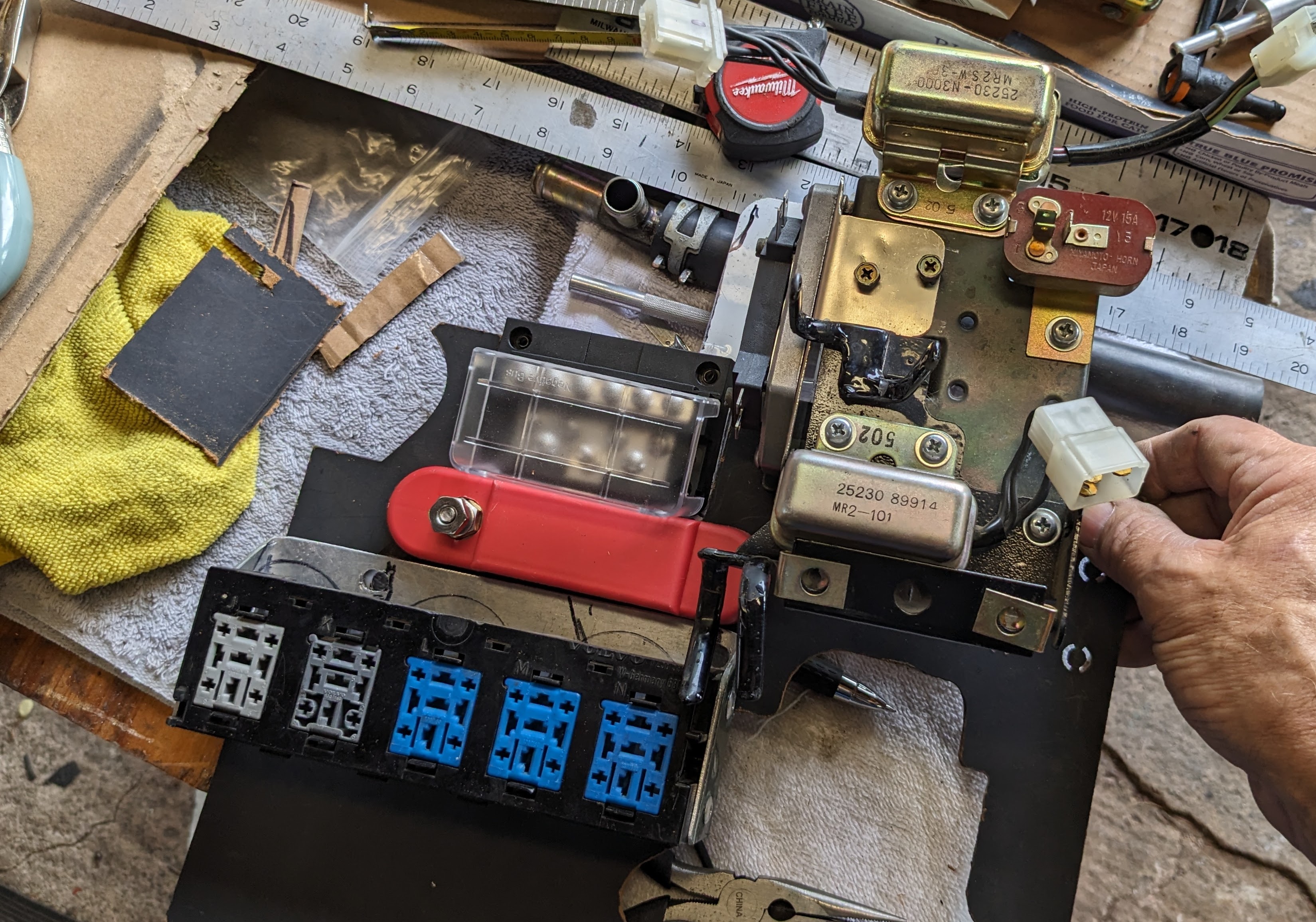
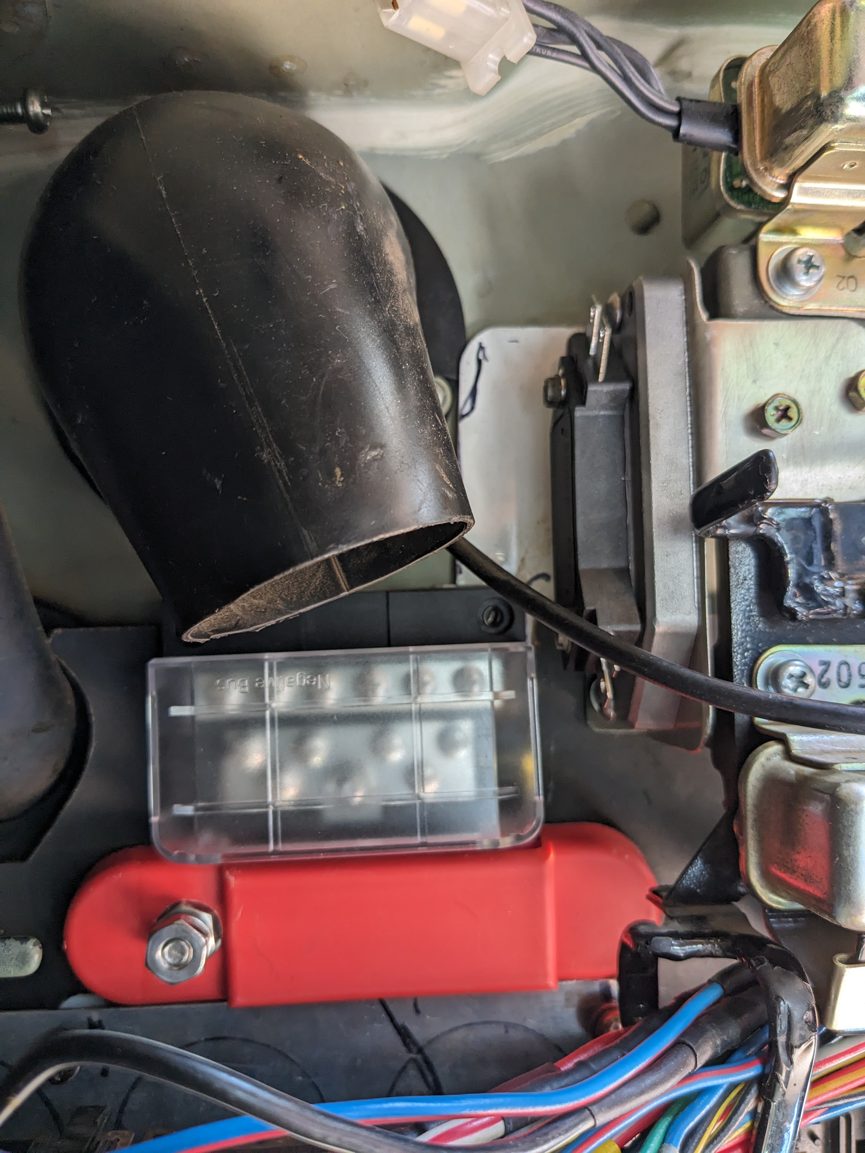
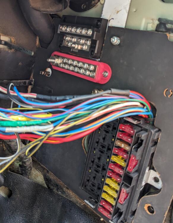
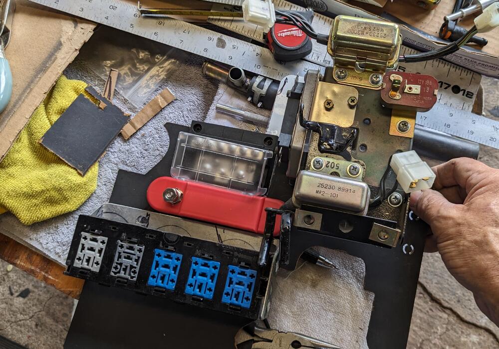
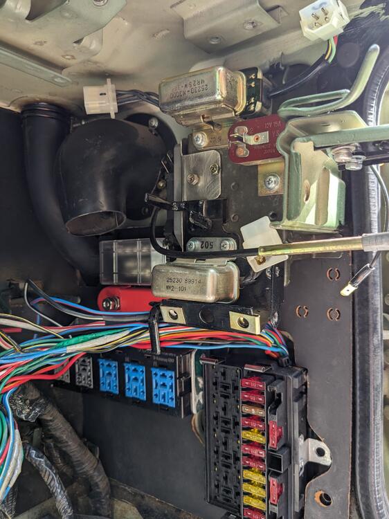
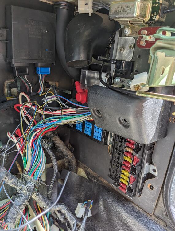
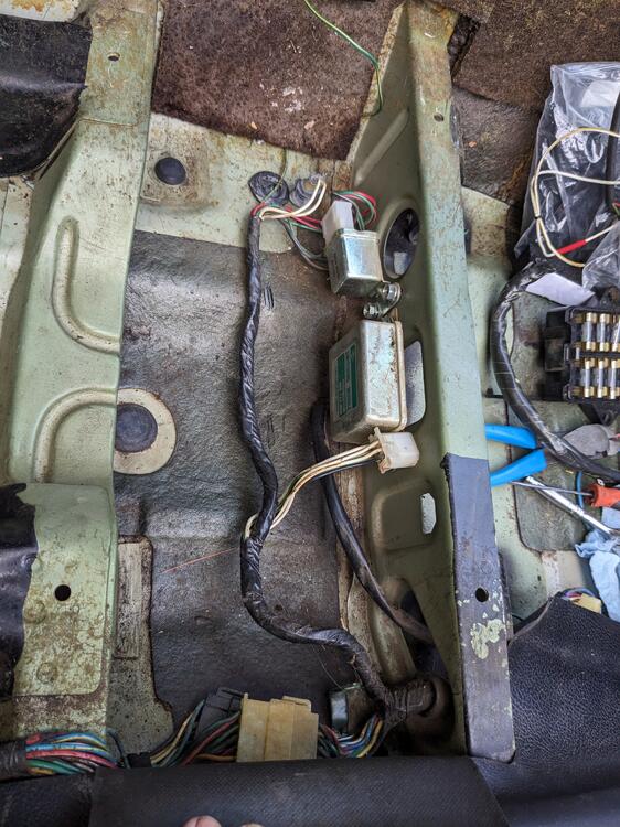
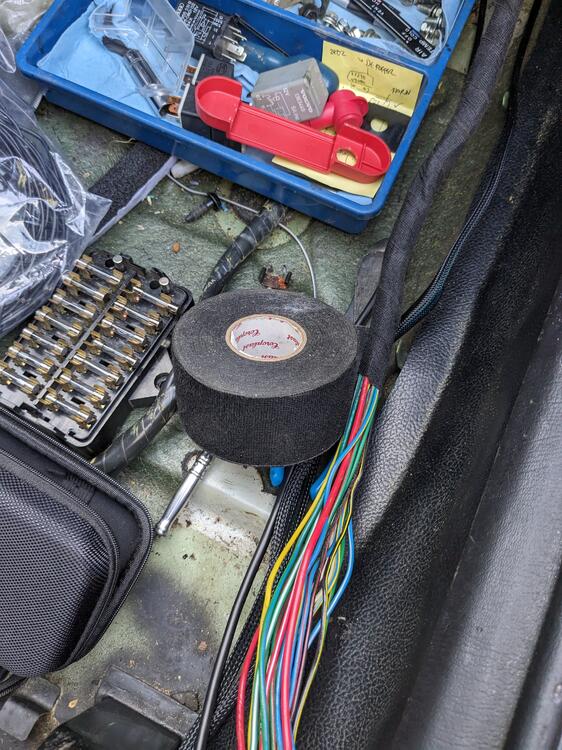
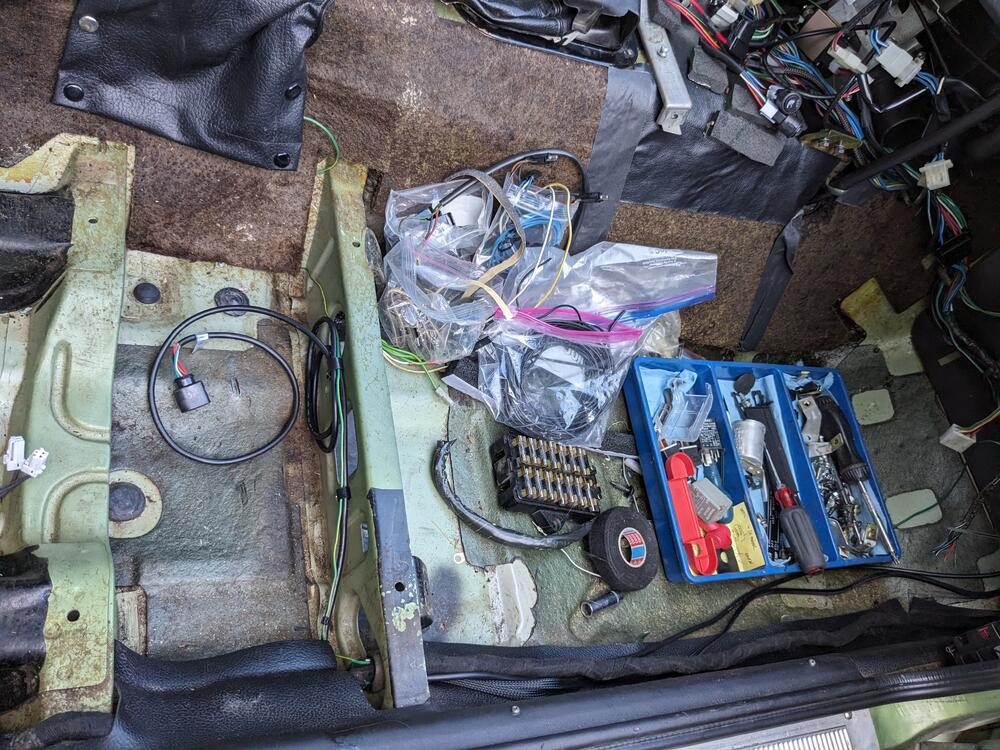
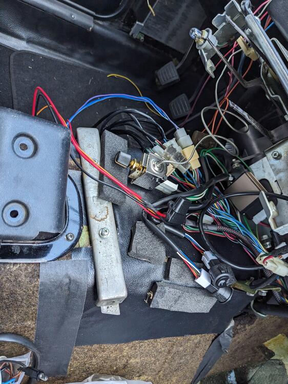
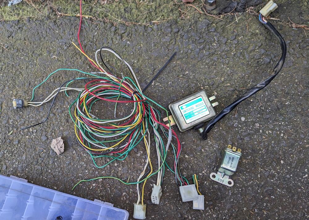
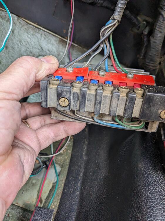
Added more stuff, to allow for expansion when I do the V6 conversion. Ground & power strips. Made a reinforcing plate that bolts using the stock mount points of the relay panel & ign module. Strips are riveted in place checking fit Stripped all the CAT / floor temp circuitry out while I had this apart added wiring for the seat heaters and WBO2 controller Have to deal with all the wiring at the console
-
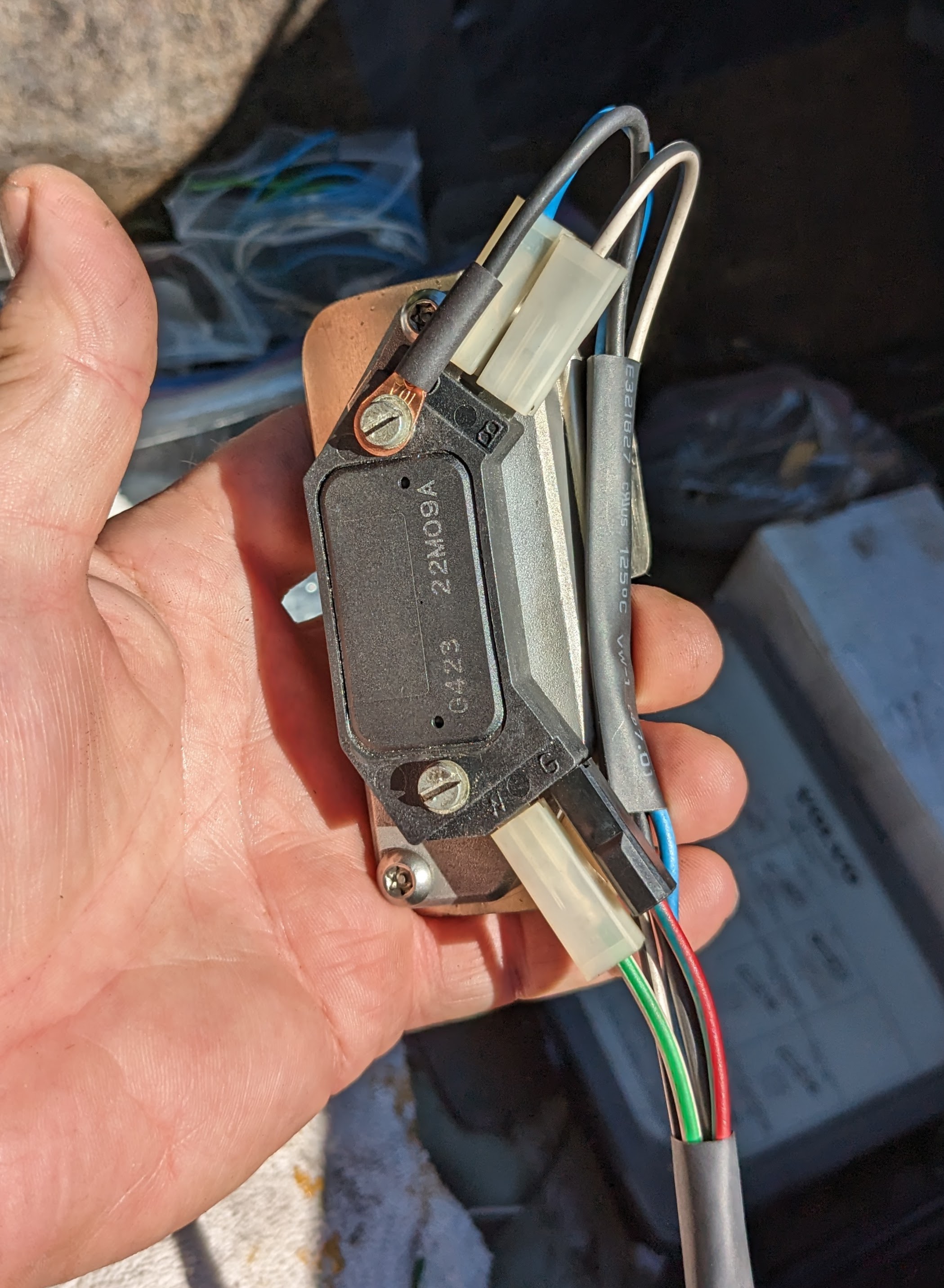
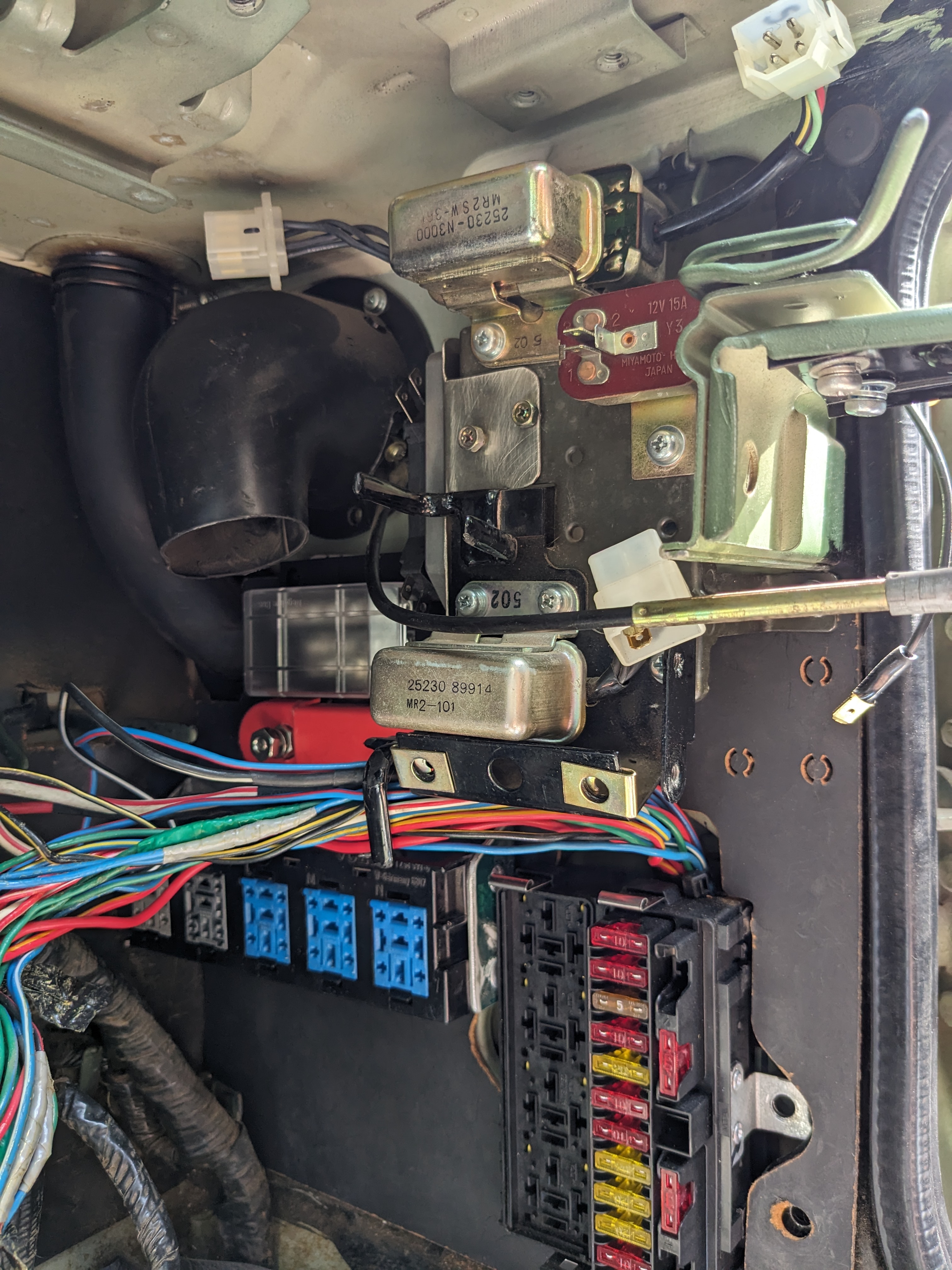
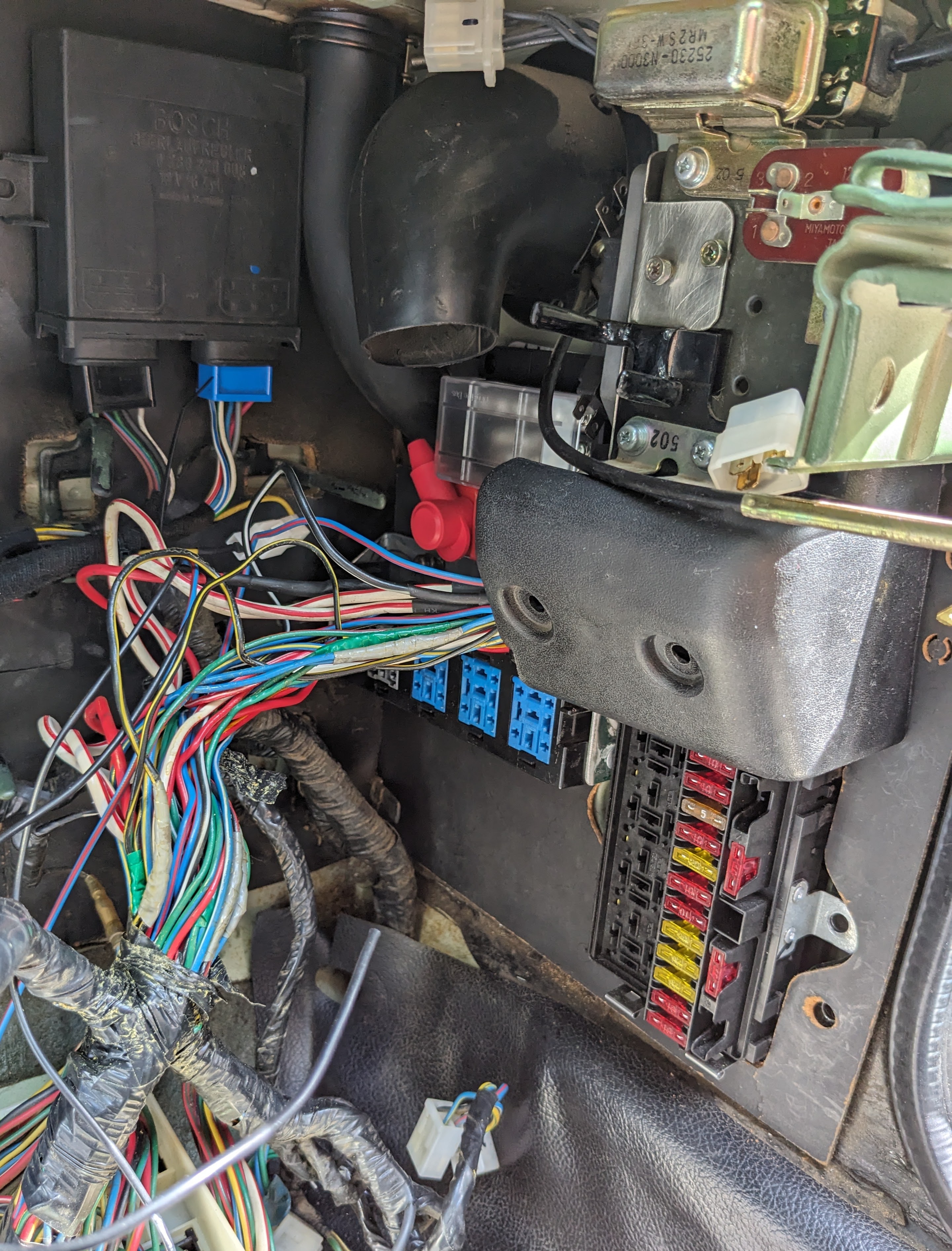
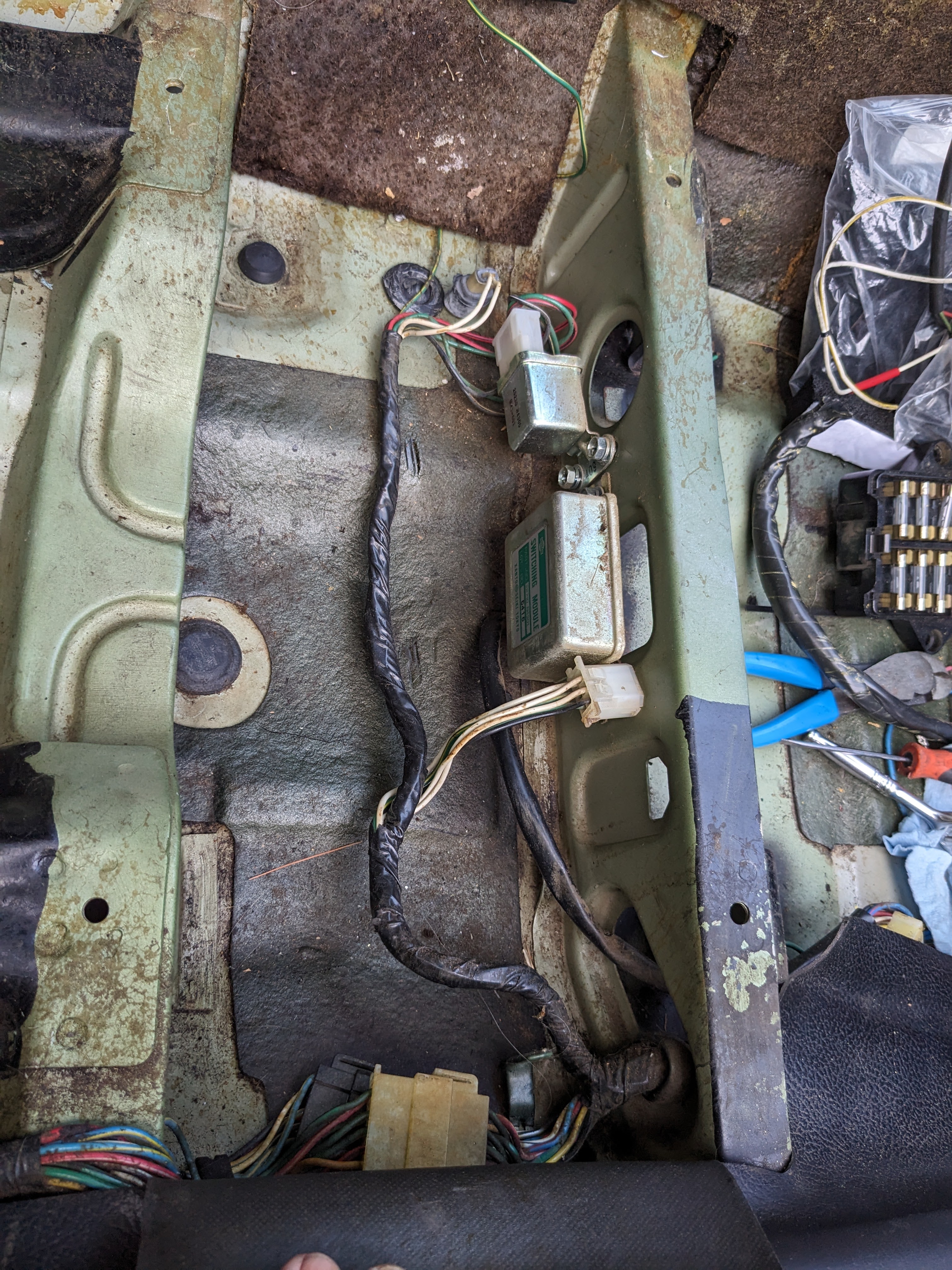
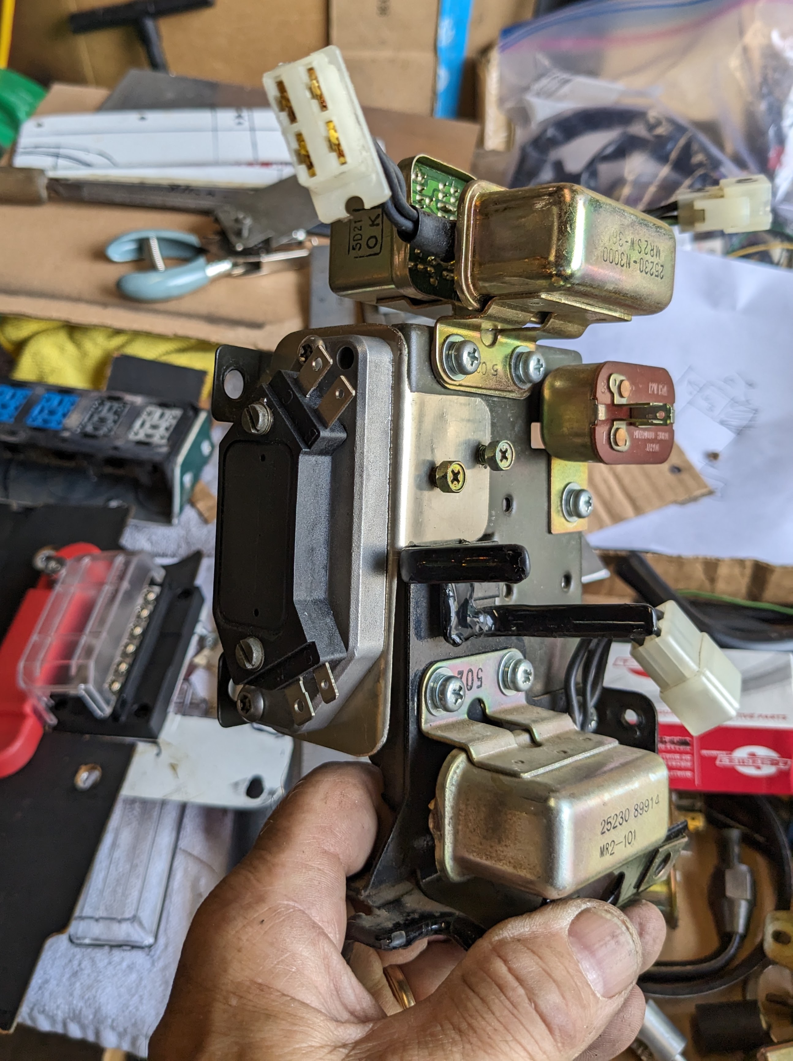
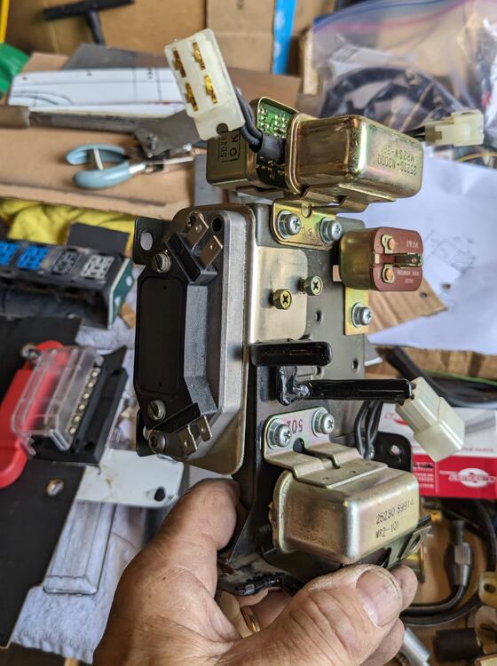
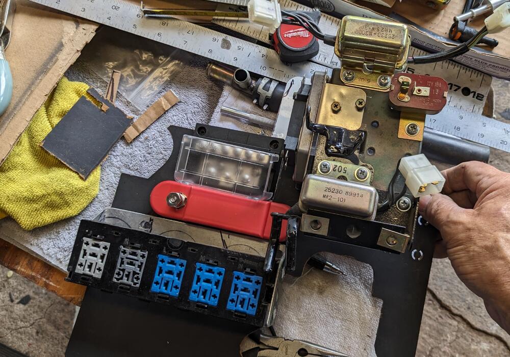
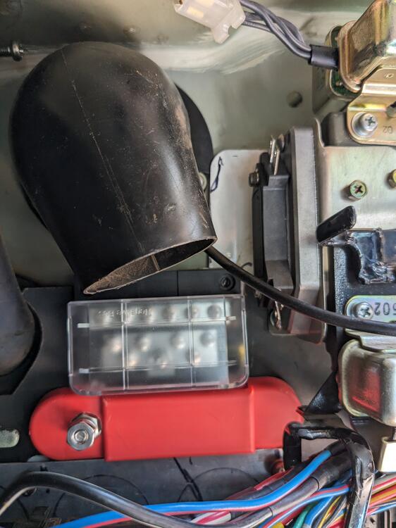
I mounted the HEI module/heat sink to a bracket I made, that attaches to the side of the stock relay bracket, where the interval relay previously lived. Made it so the assembly is unscrewed from the face, as the bracket screws are otherwise inaccessible. I'll make a sub-harness so that the module can be removed with that attached
-
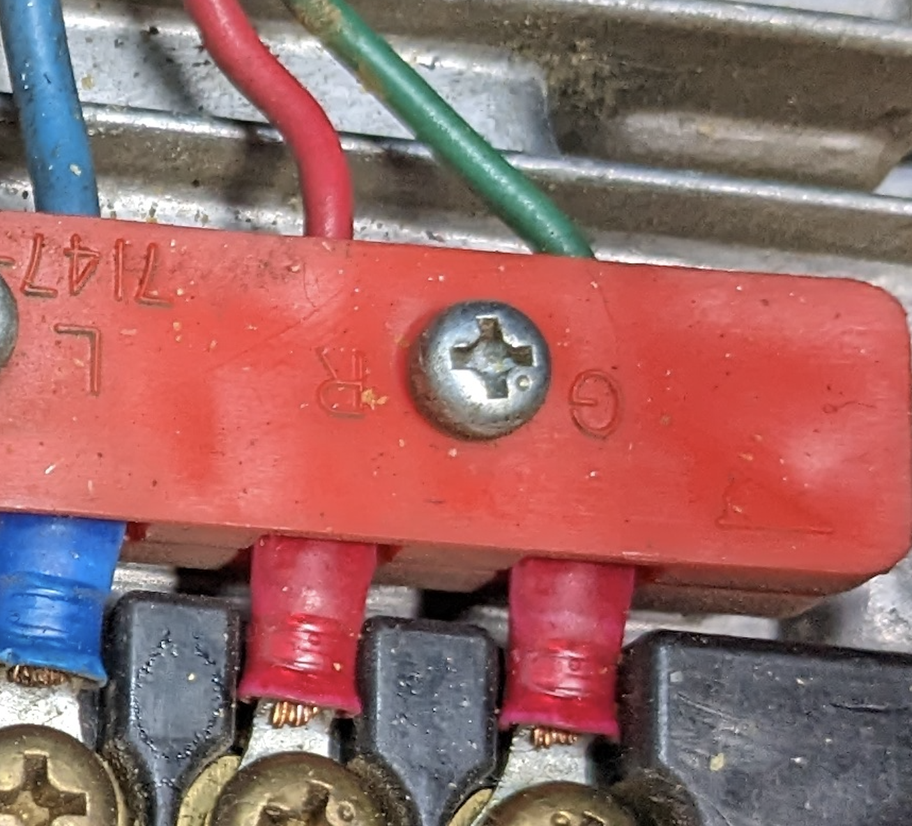
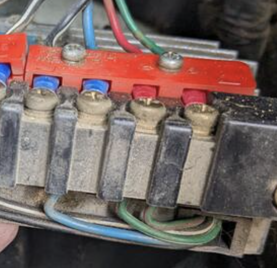
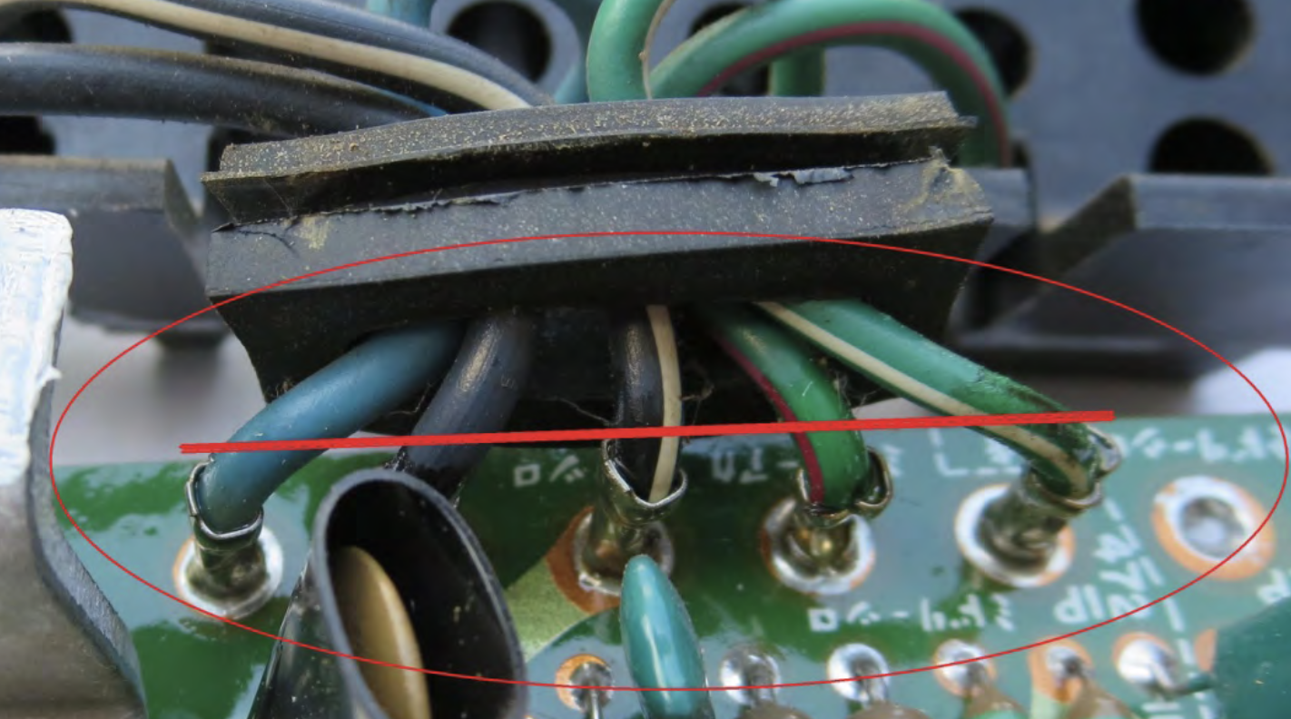
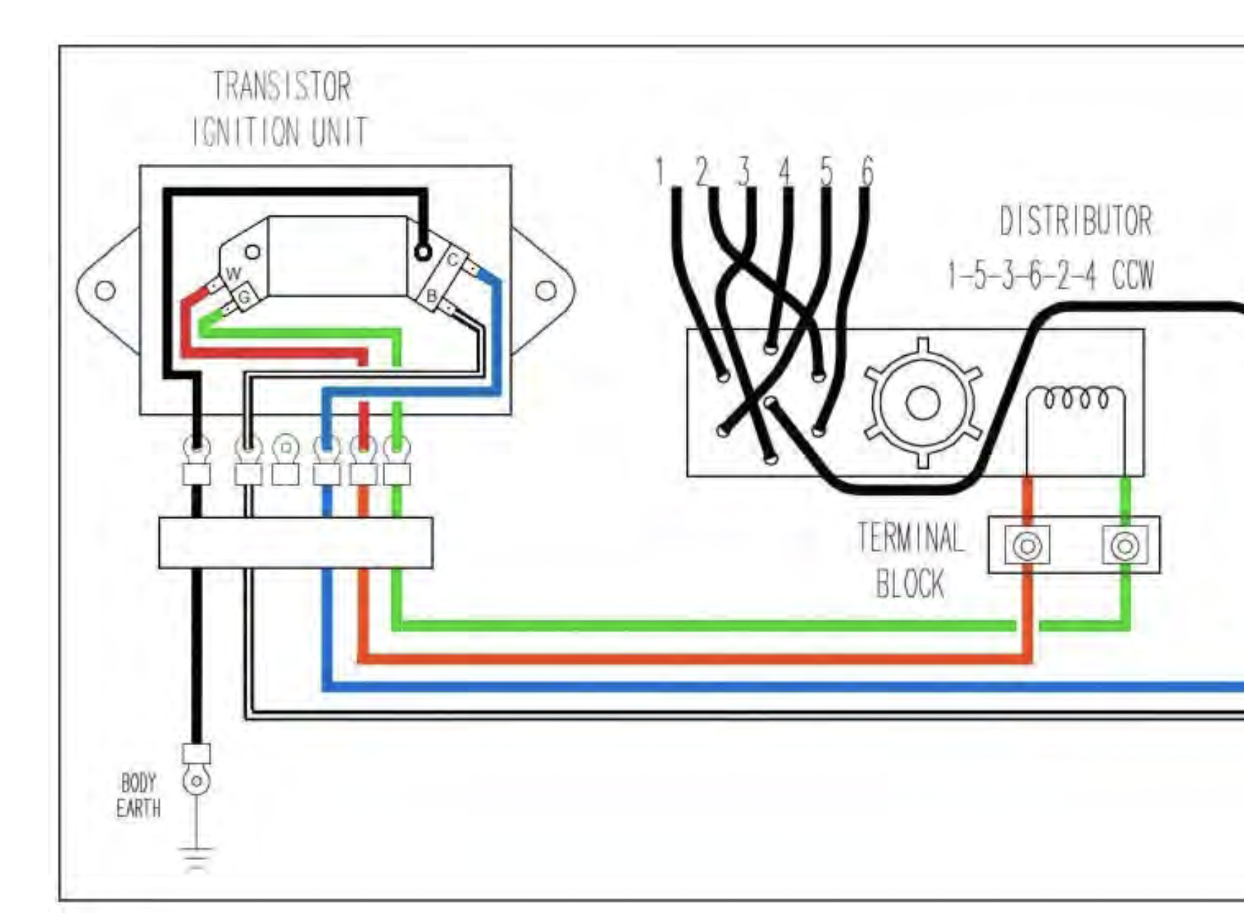
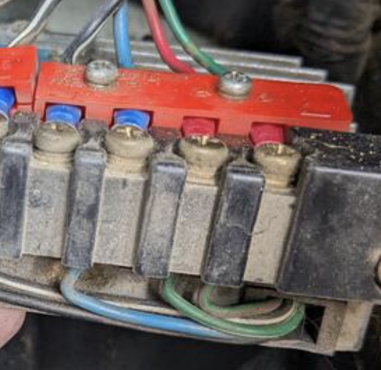
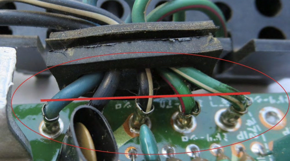
I see the G & W on his, I just have no clue what he means by W... Not sure what you mean by having it backwards though - the Gn wire goes to Green-Red on the module side, the Red goes to Green-White I am aware of the labeling on the wire retaining strip, I just didn't know if it was a difference between CA market & others, since there was another poster who said he had to reverse the wires compared to the same pic of his with the red on the outside... Crop of his pic from directions

-
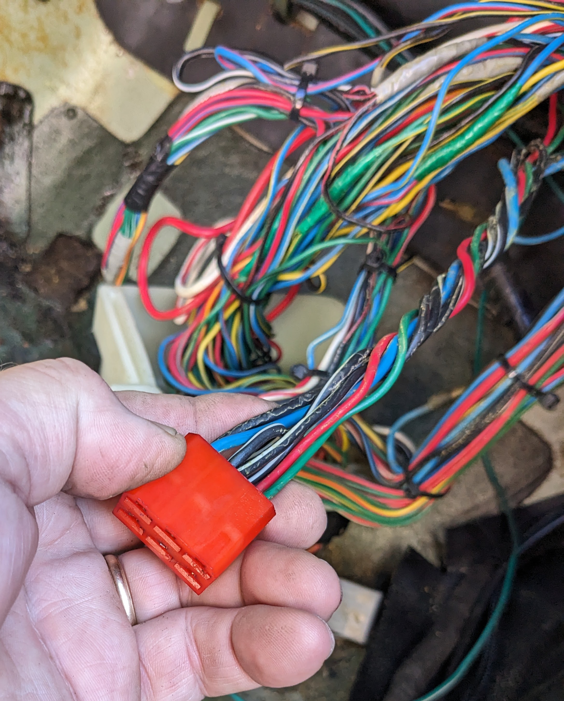
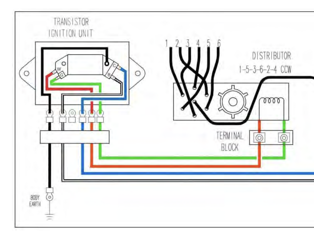
Thank you. On a side note, reading the FSM diagrams drives me nuts, since the wiring illustrations are from the terminal side of any given connector, compared to European format which is always viewed from wire side of any given connector. I'm already good at getting dyslexic with wiring, having to translate the pin locations in my head from the diagram to the reality just adds to the potential for error on my part. I always double-check my wiring anyway, with these it just takes even longer. OK - So I'm going to assume the pin configuration he illustrates is still accurate for the HEI then, with Gn going to the small leg on the HEI He doesn't actually list or show the physical wire transfer/connection within the module to the HEI pins: G (harness) = Gn-R (module) R (harness) = Gn-Wh (module) Mine has 2 Blk/Wh wires, middle one appears to be redundant - since there is no connection on the module side. Not sure if I should join the 2 together for the HEI, in case there is some reason the 2 are required.
-
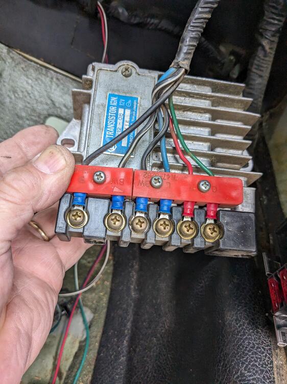
@EuroDat - I removed my module today, and the wiring of the red & green is reversed compared to your directions. Mine is a CA market 75 280Z
-
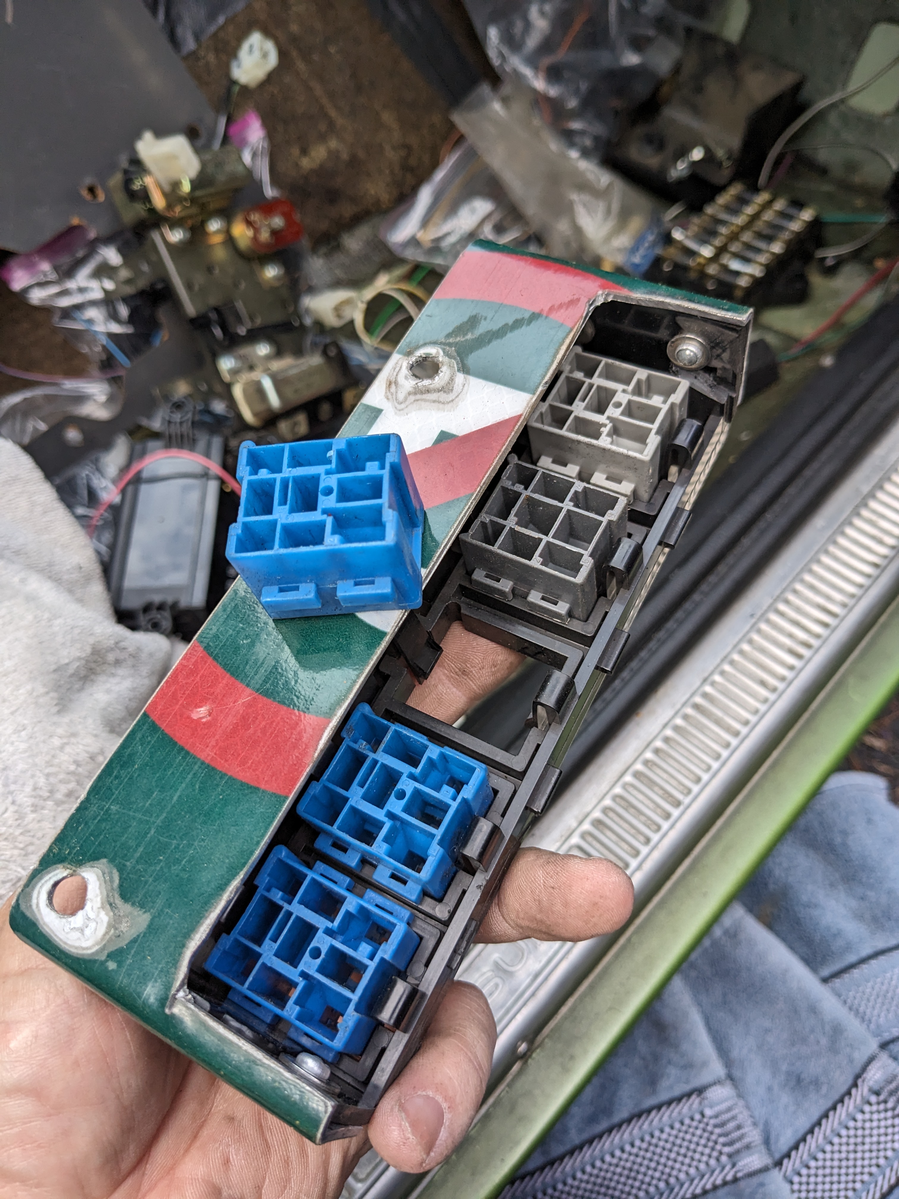
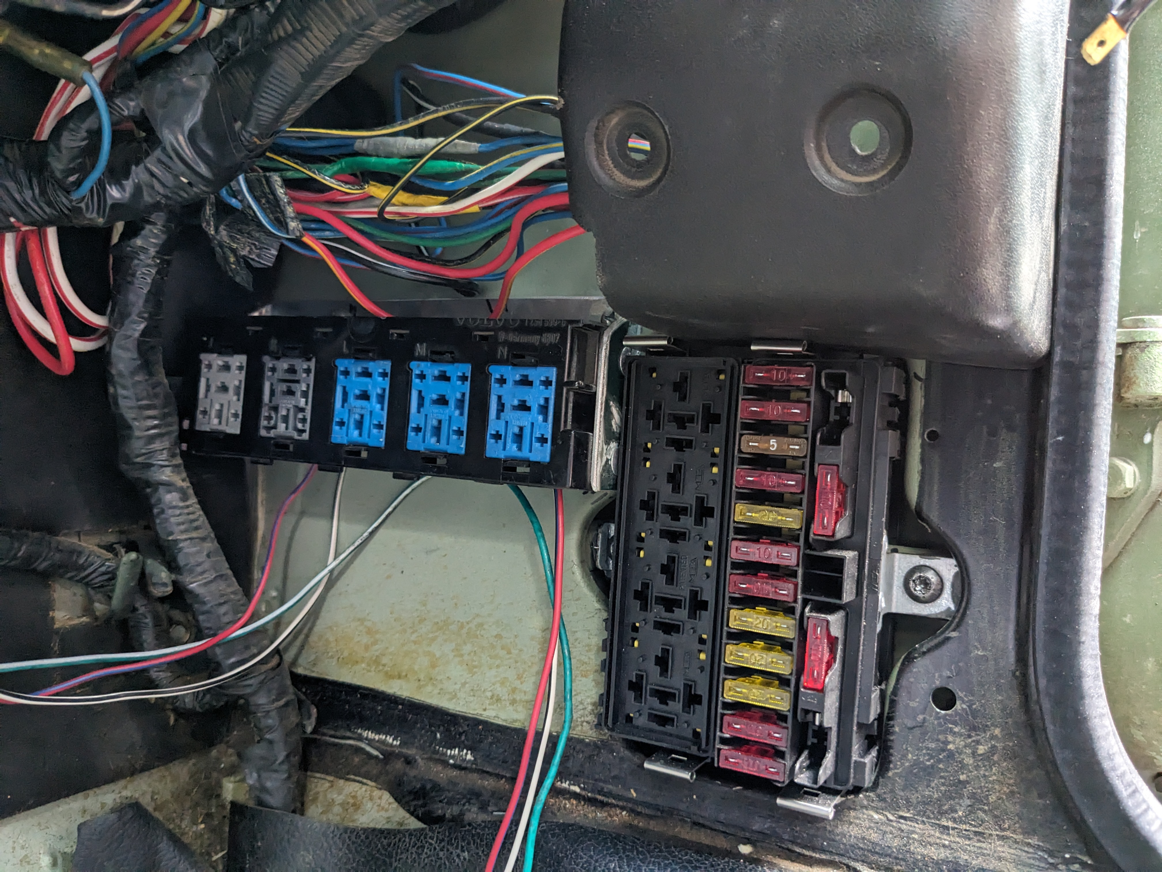
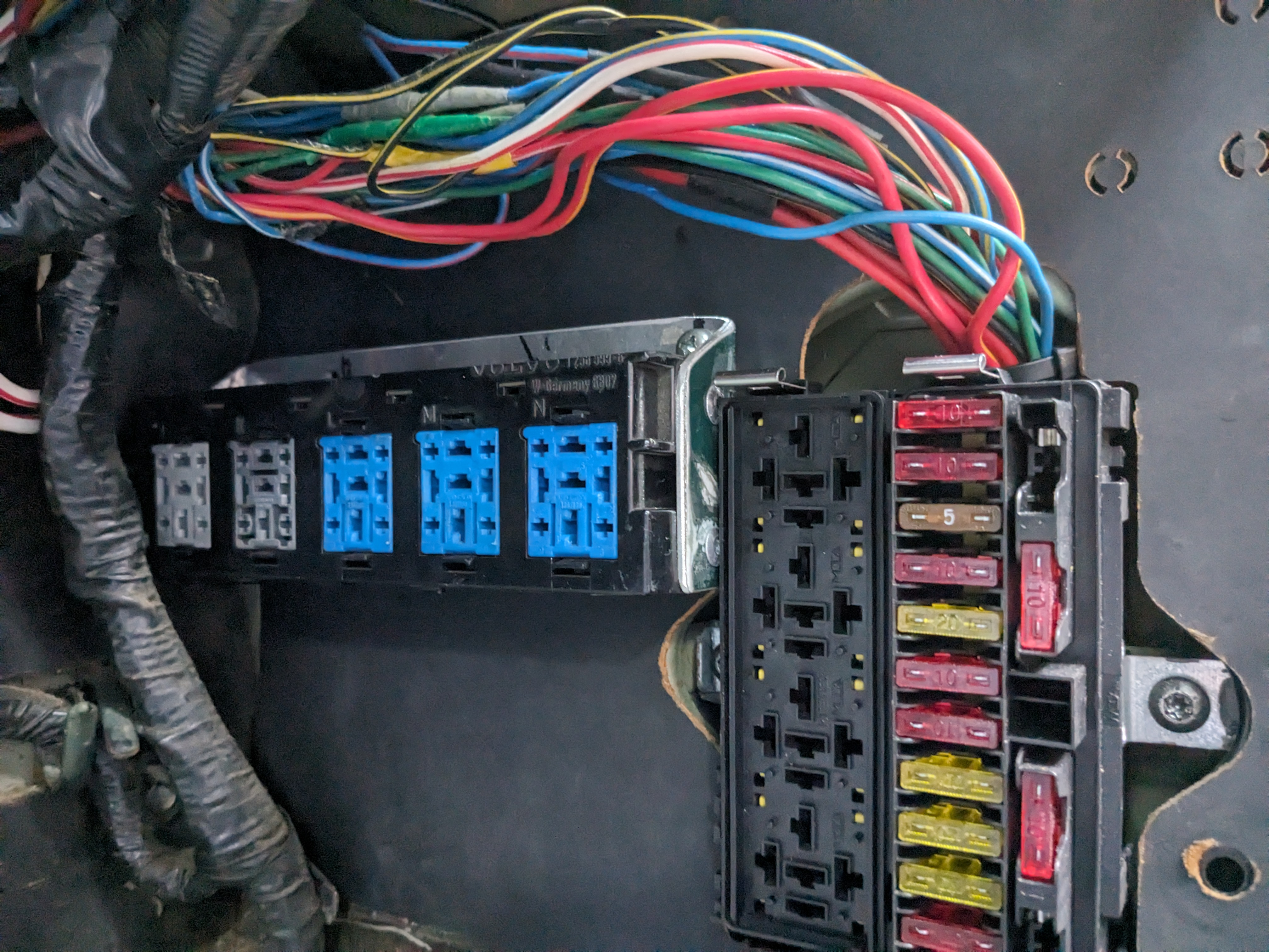
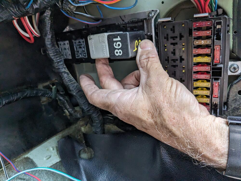
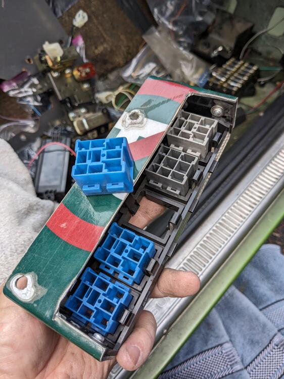
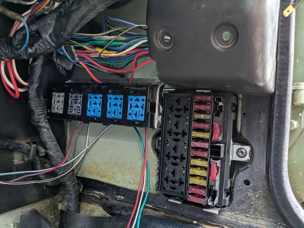
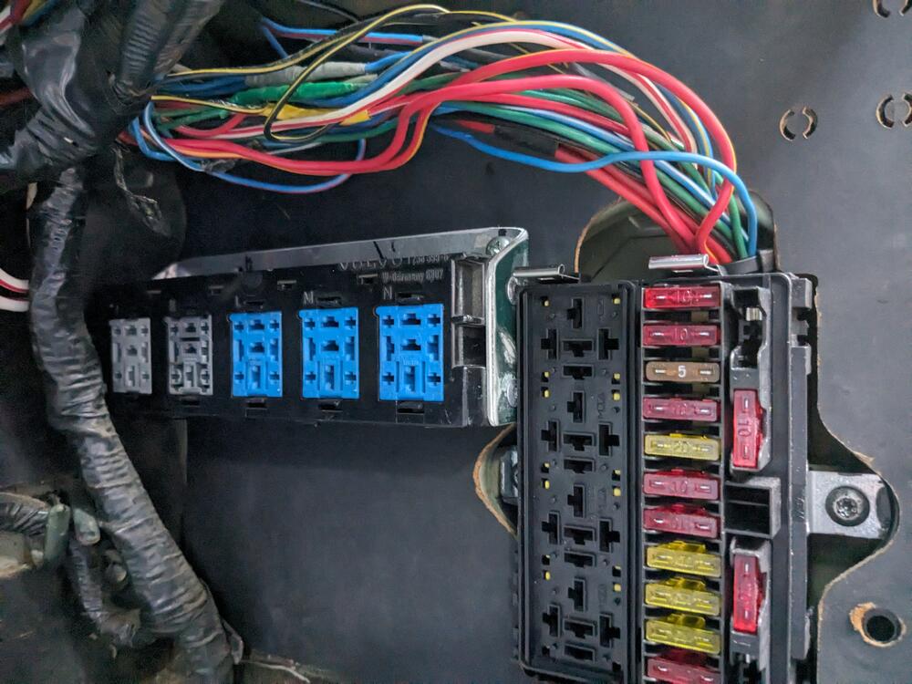
Figured out how I will address the relay installation issue. I made a bracket to support a row of relay sockets cut from an '80's Volvo 700 series fuse/relay box backside - have to be able to remove the relay socket inserts as needed mounts using factory location of the ignition transistor module factory trim panel works fine
-
Everything in the system is new, besides the evaporator. I will be using R134a. The compressor I have was intended for R12, which is why I have to remove it & drain the mineral oil before I go any further with it.
-
You're making my head hurt. I have enough trouble doing the math to determine resistance in parallel 😁
-
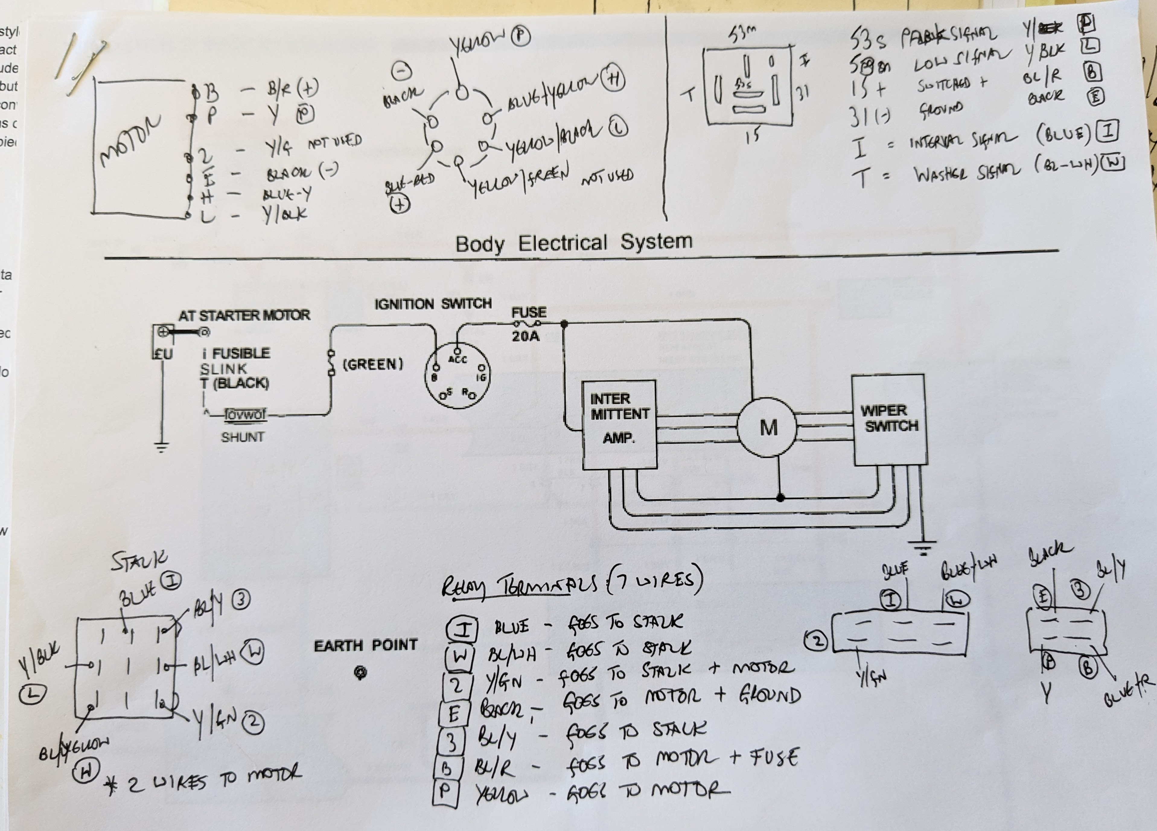
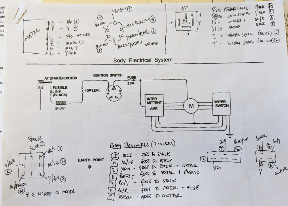
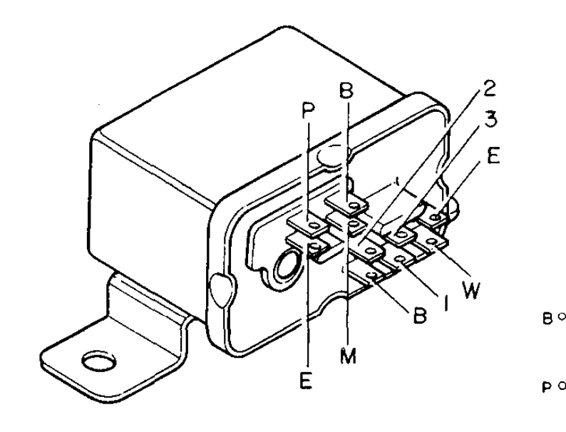
@SteveJ - I tried to quote your post & move it here - didn't work, so I copied your notes: "P = Park M = Motor 3 = High E = earth/ground B = Battery I = Intermittent W = Washer 2 = Low Notice that the 3 isn't shown on this diagram and is also unused on the 75. Oops, I made an error. The 75 wiring diagram shows the 7 terminals being used. I think I made the right corrections above. The weather is cooling off soon, so I may be in the garage more in the near future. I can do some testing I've been wanting to do." So, what gets confusing is the use of the alpha & numeric terminal locations. The motor diagram shows H & L, so having 2 also represent Low makes no sense. I made a sketch with the motor & plug, the stalk & relay, so I can figure out which pins to use for the VW delay relay. 2 (yellow-green) isn't even used with the Honda motor, so it clearly has no current bearing on any operation.
-
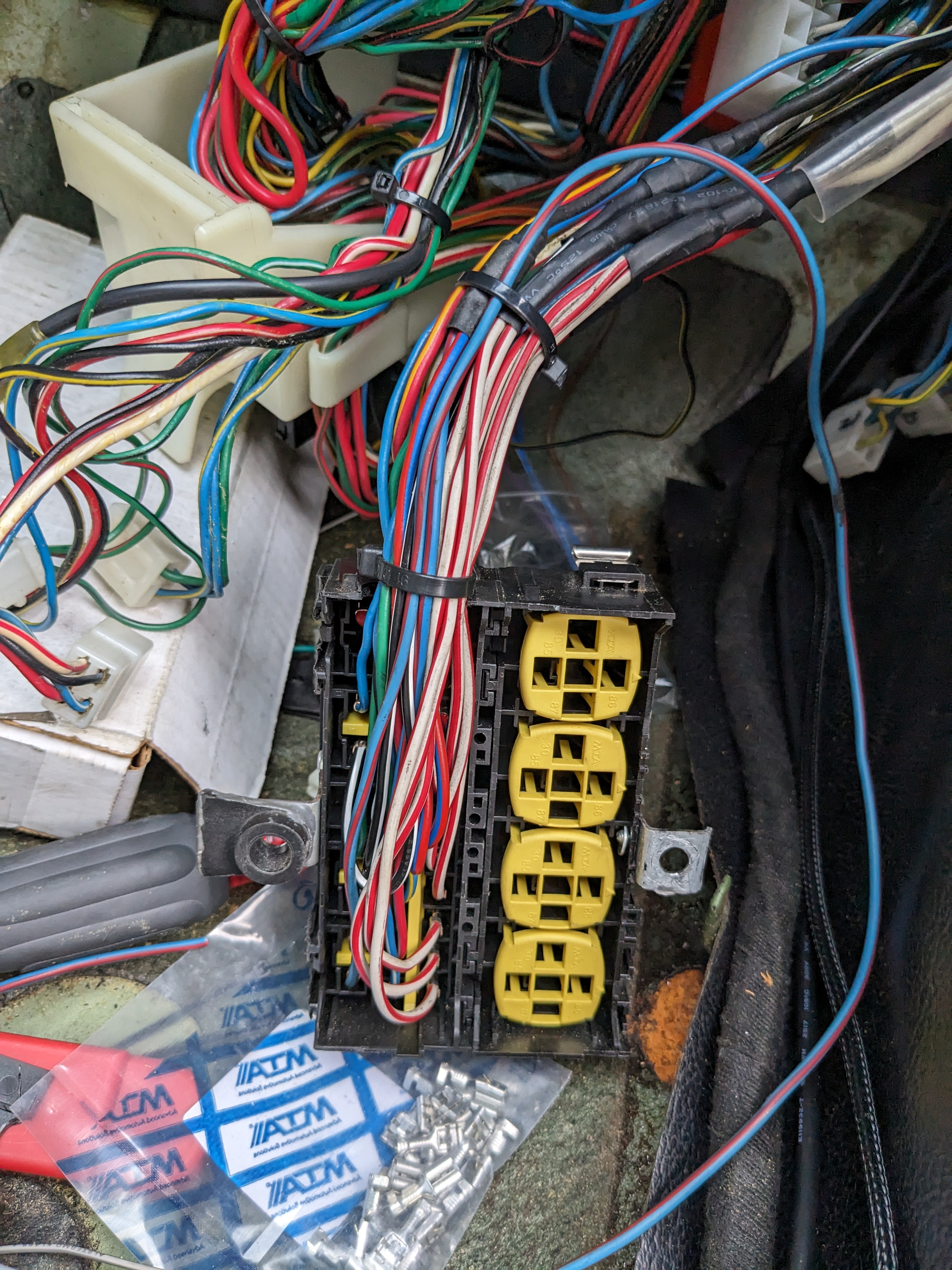
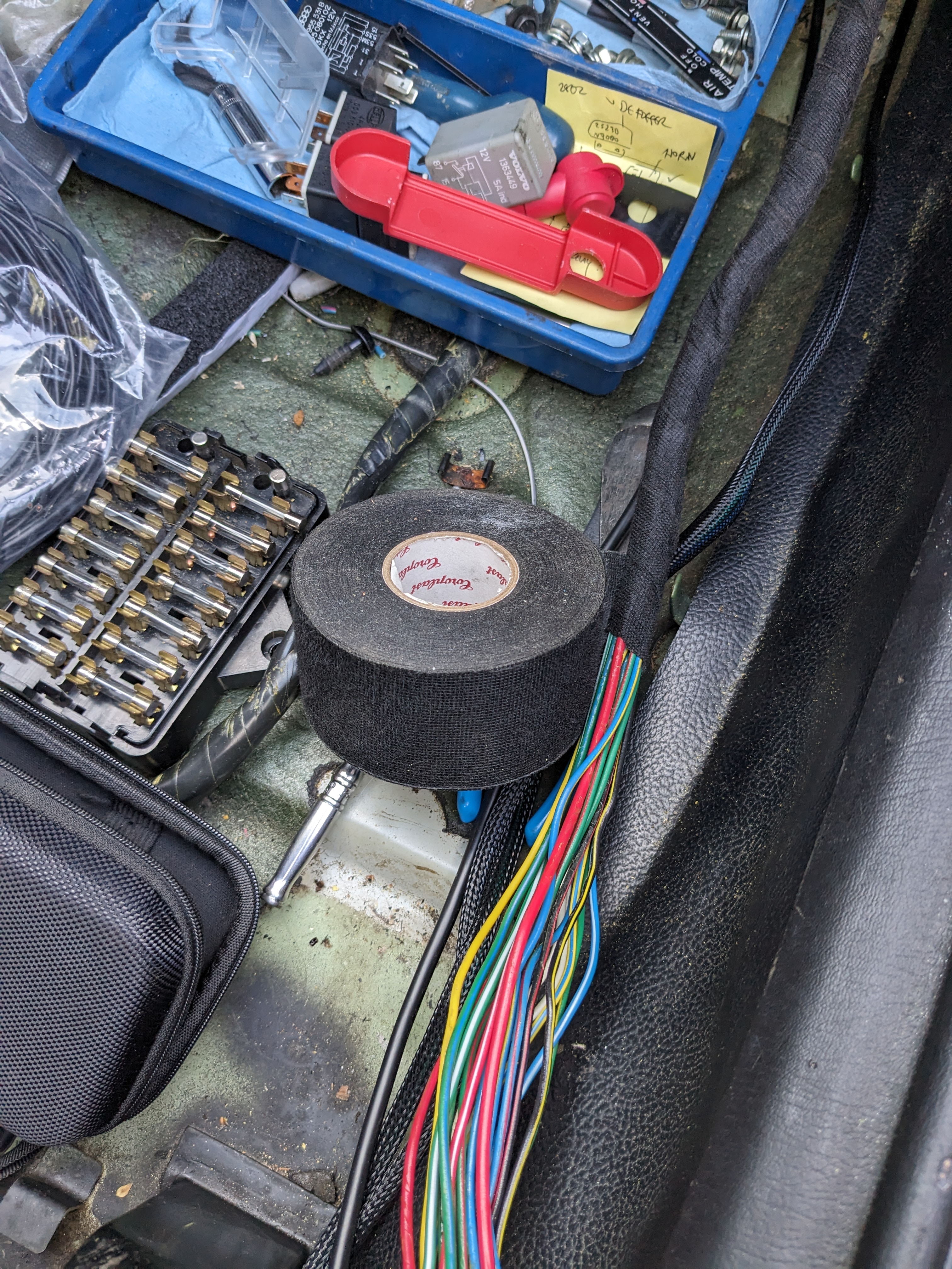
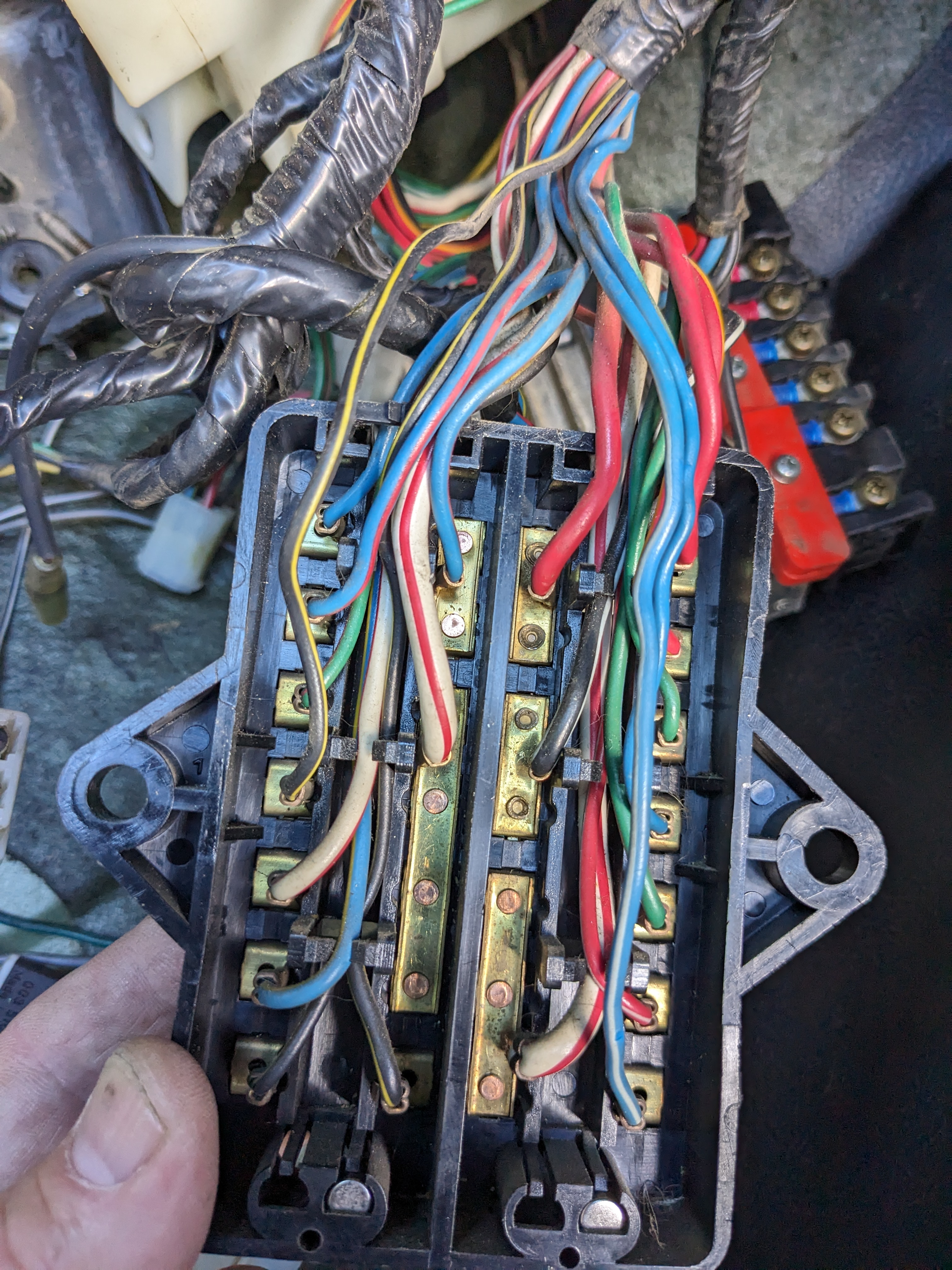
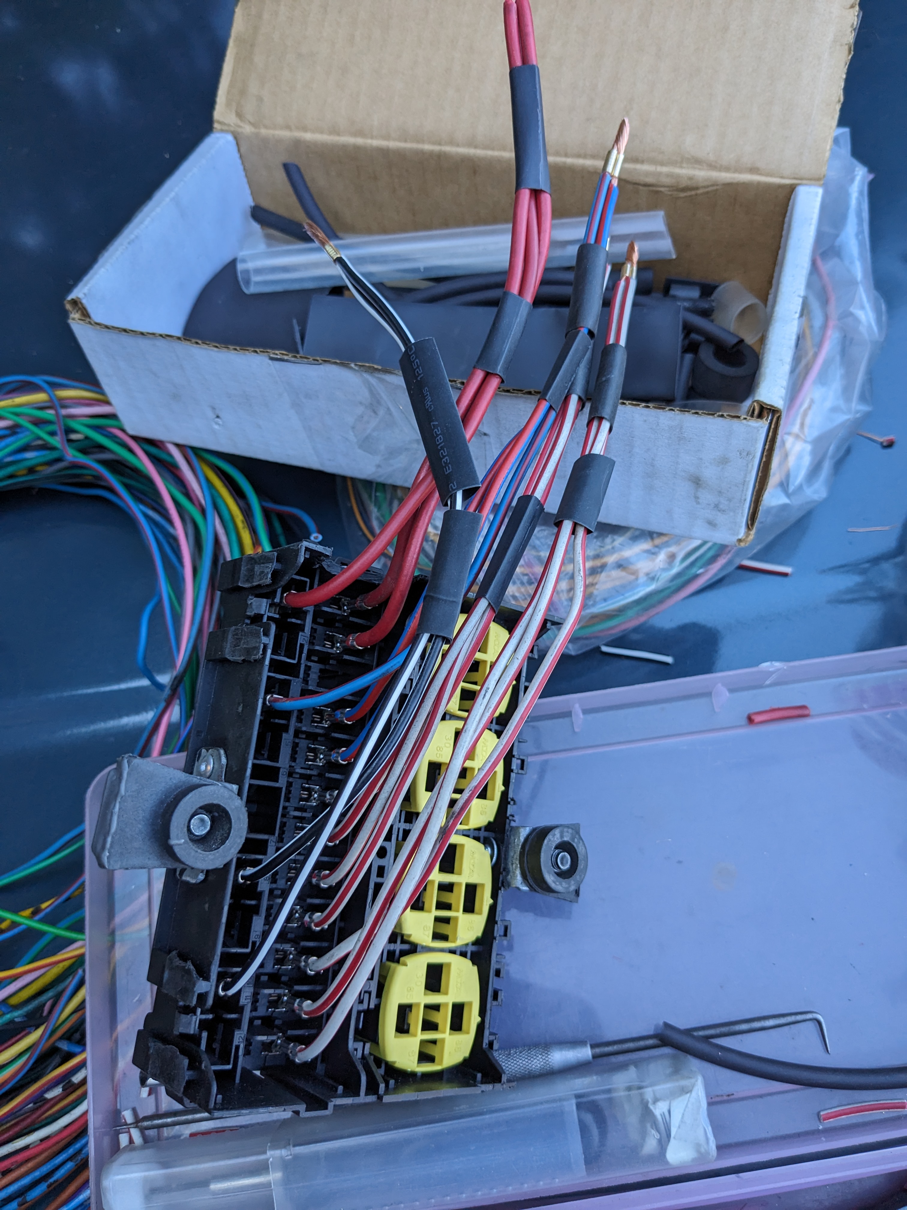
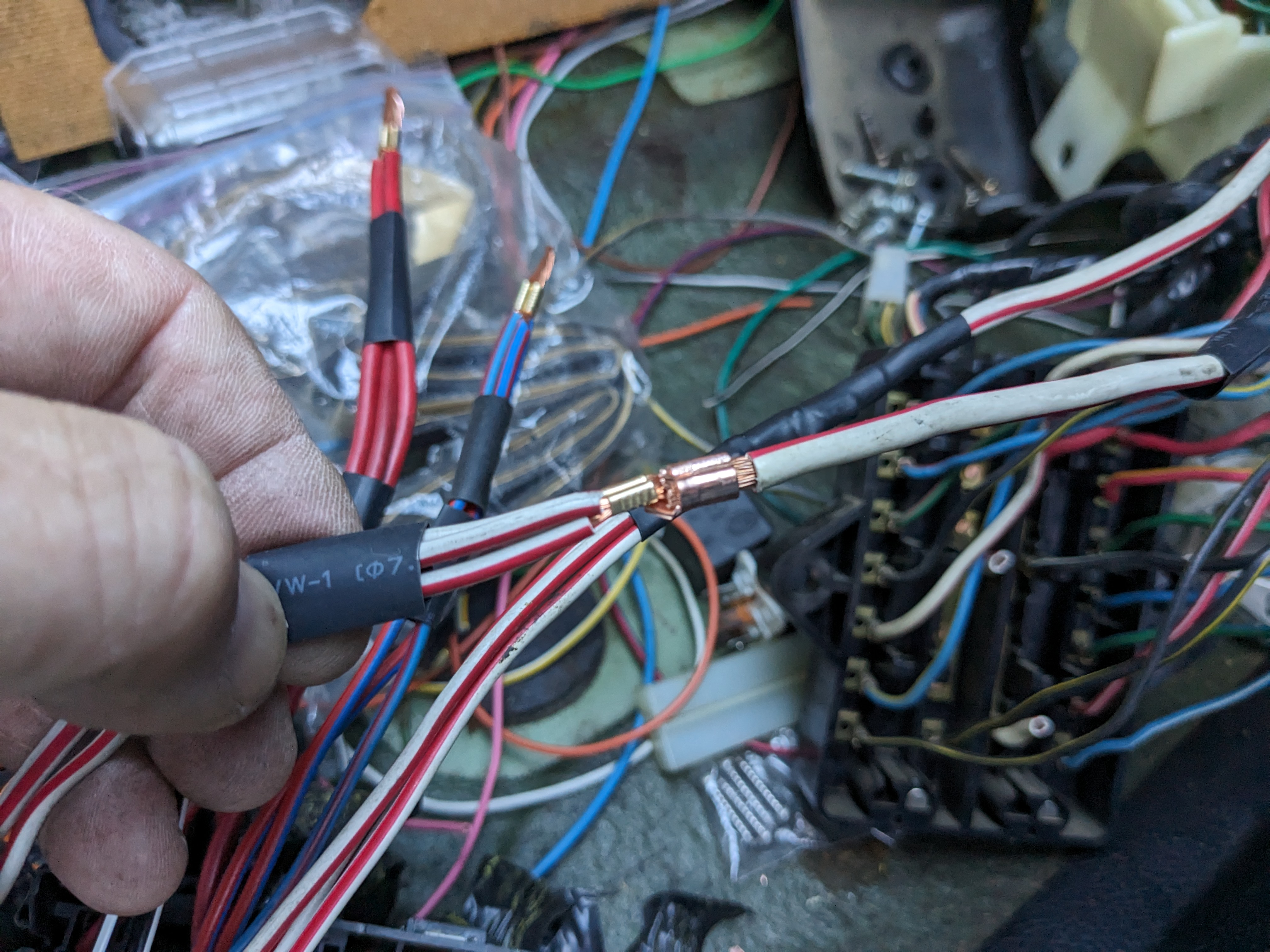
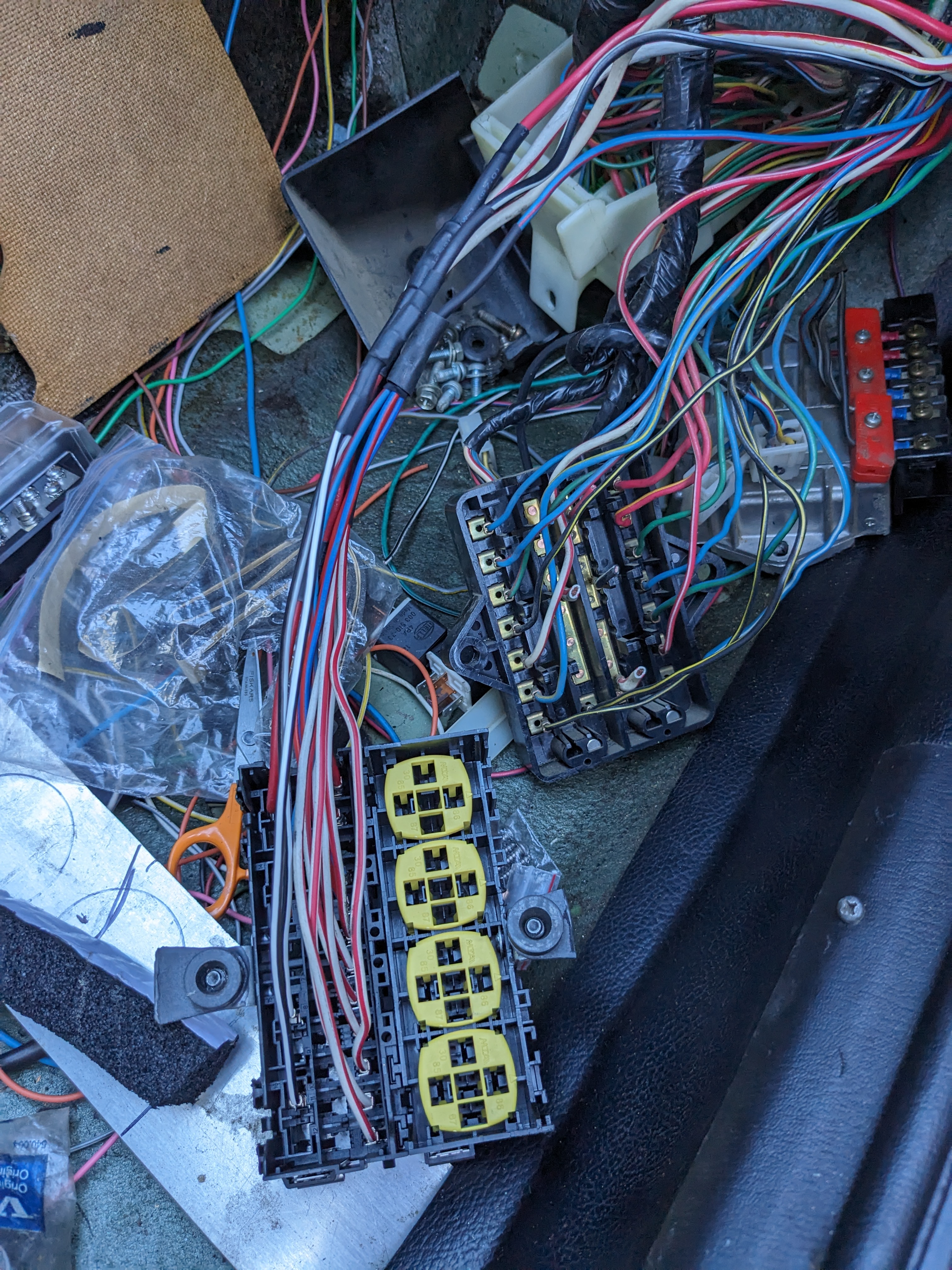
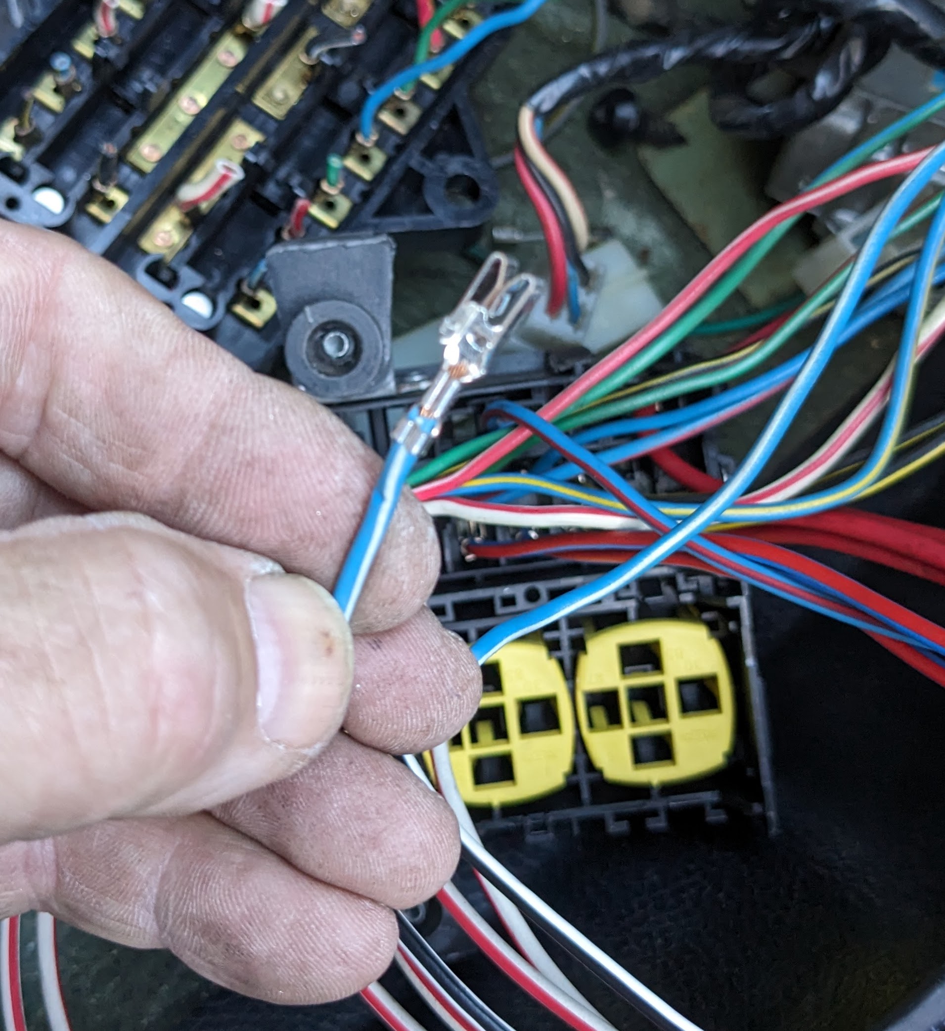
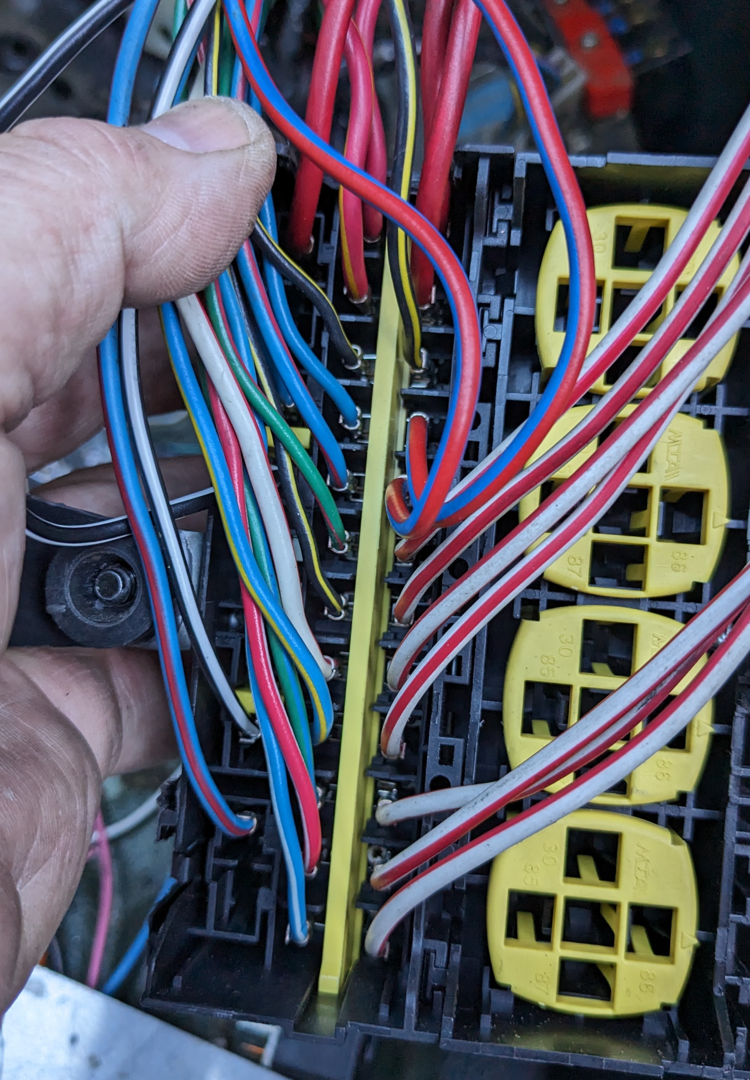
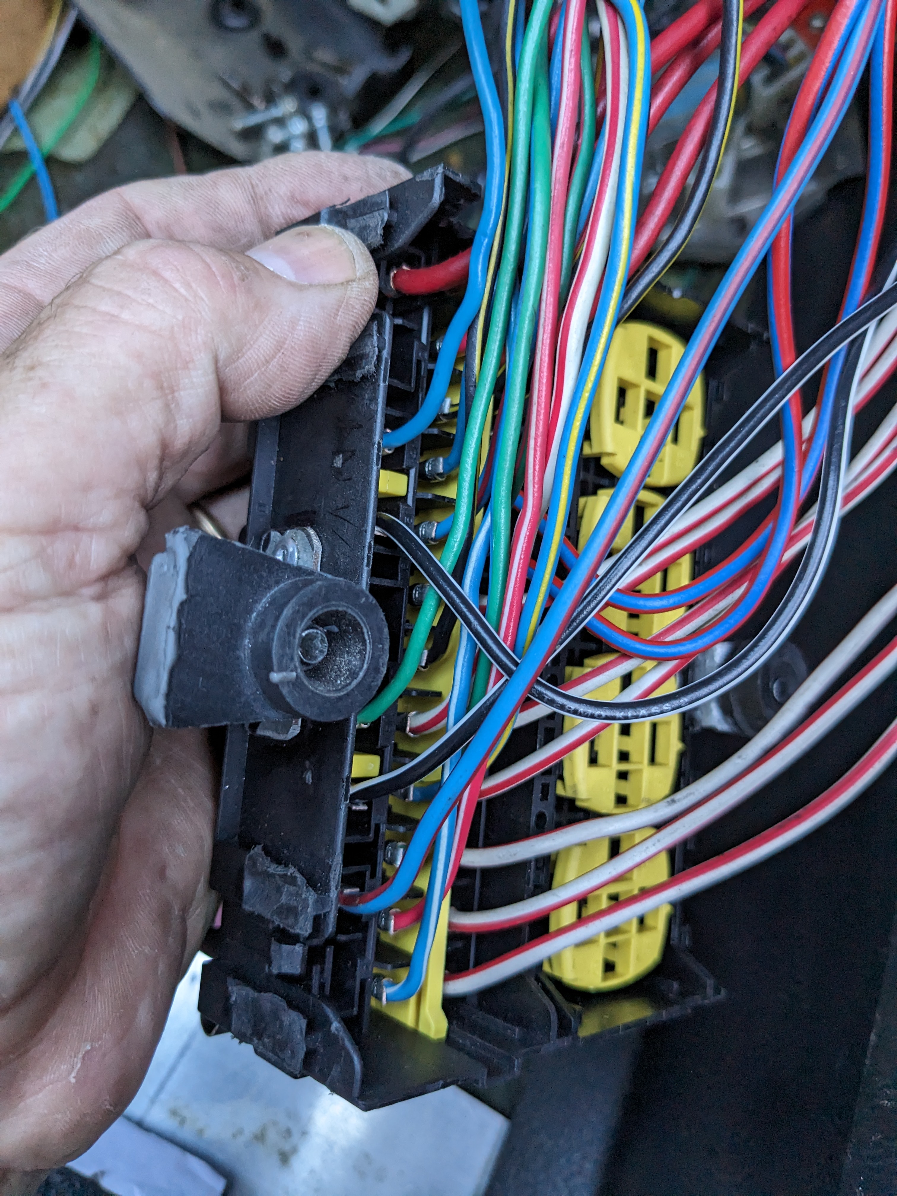
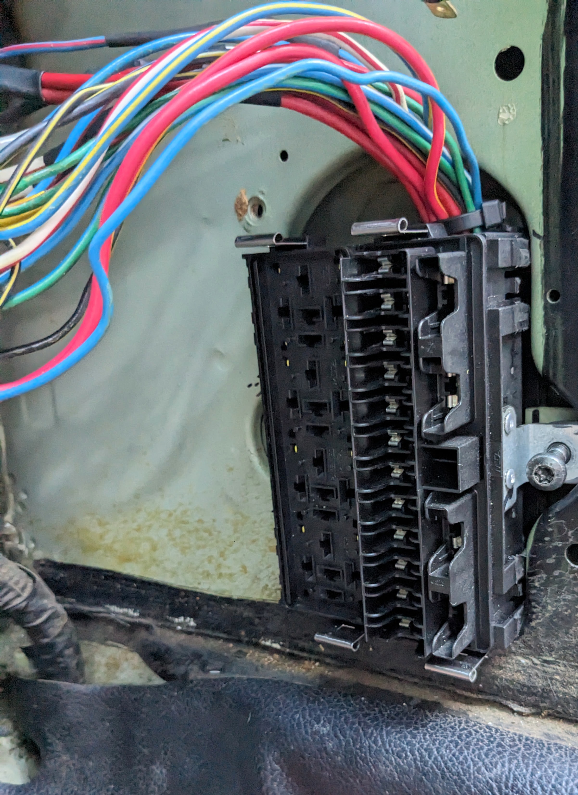
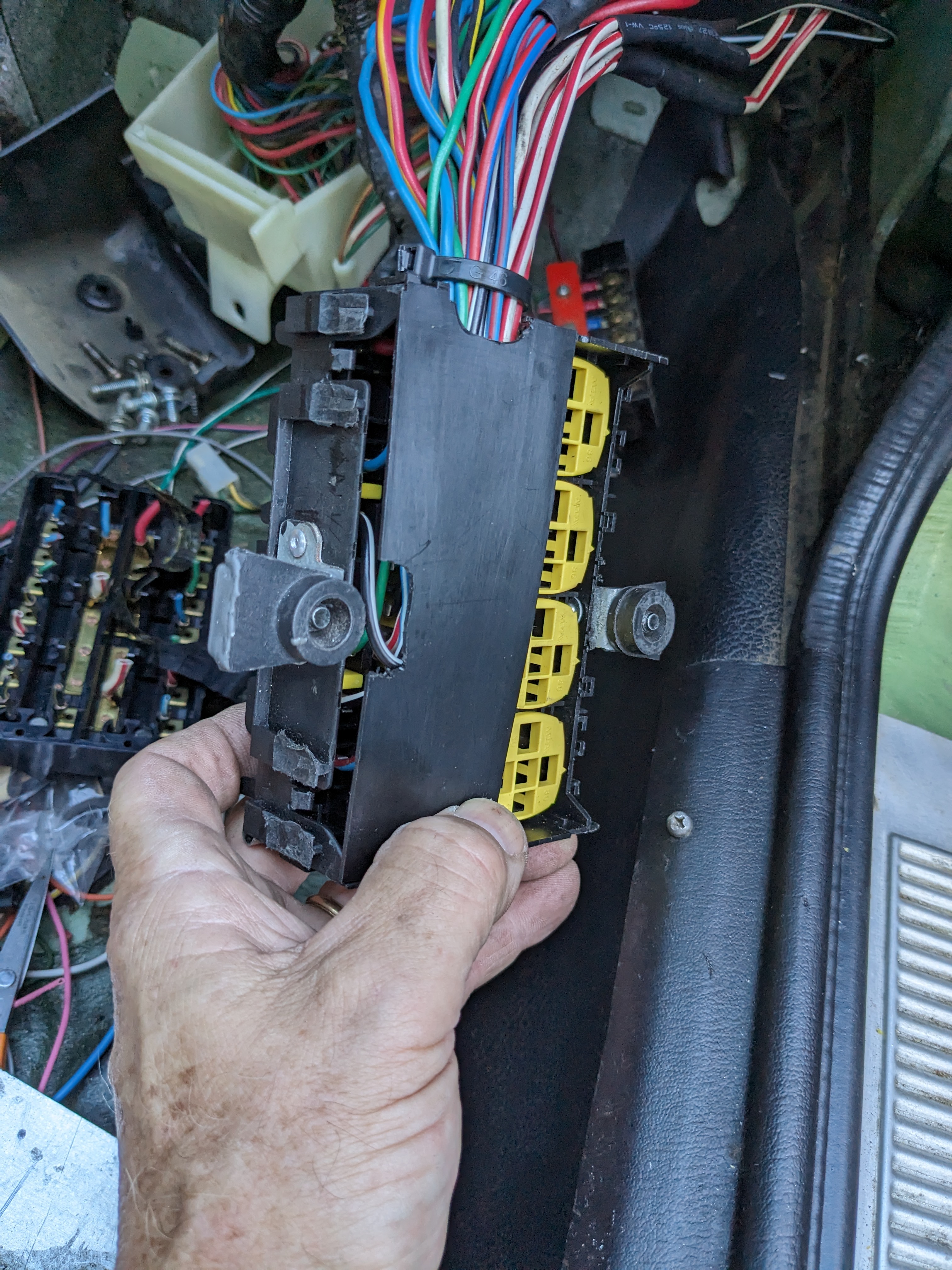
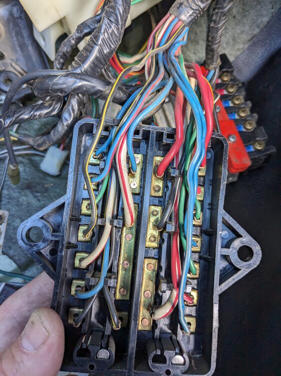
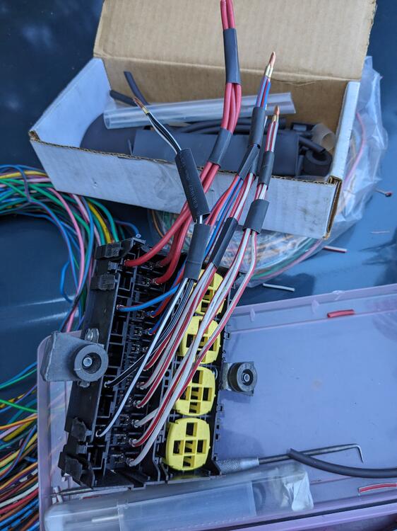
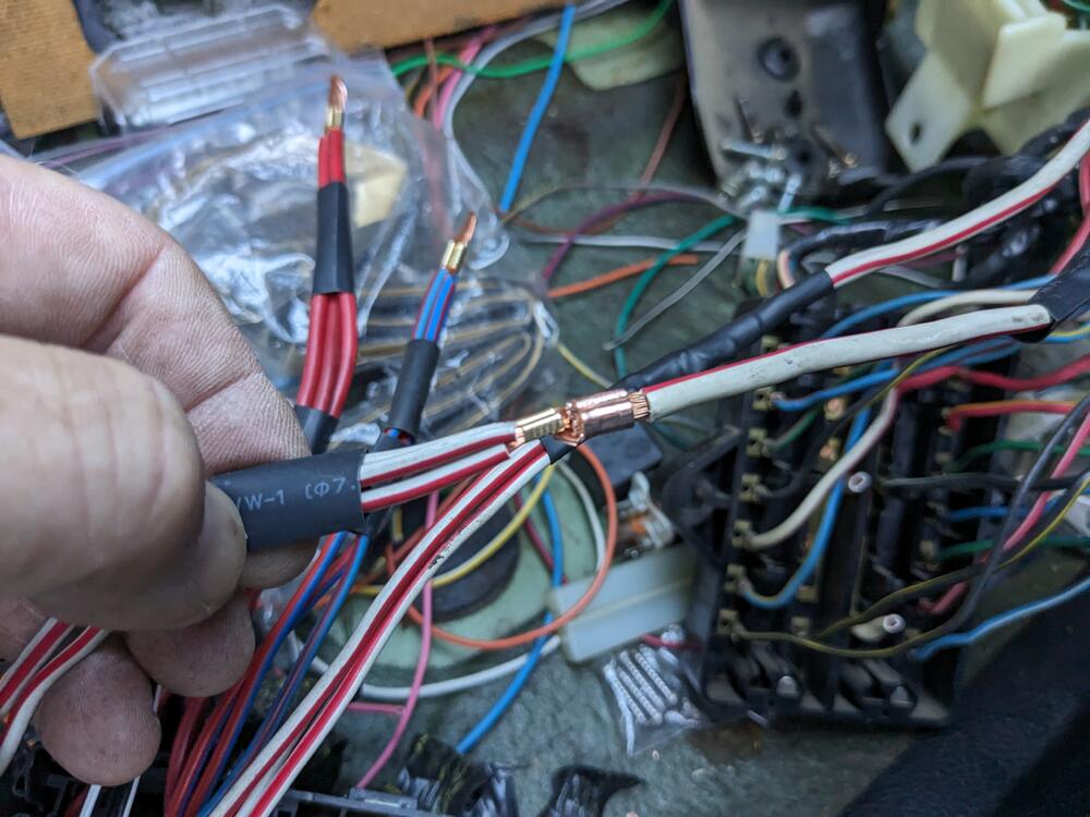
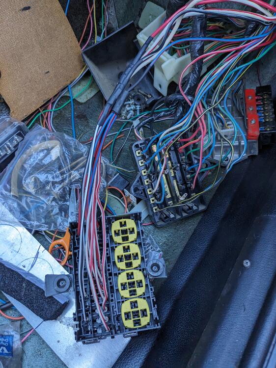
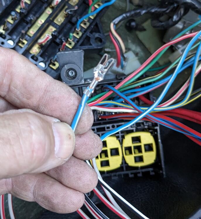
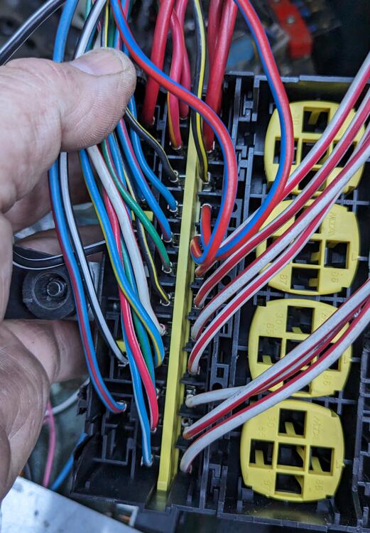
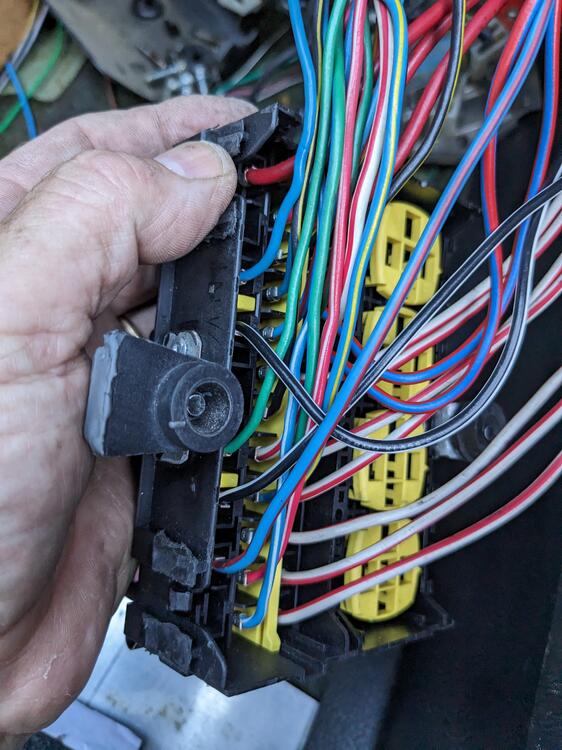
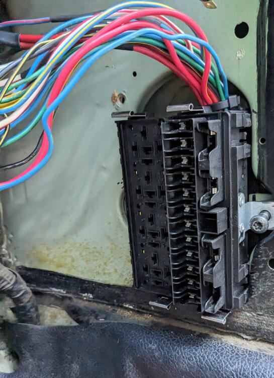
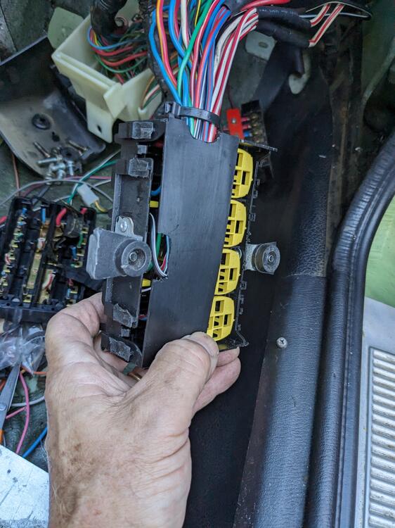
Cut out the Fusebox today & wired the Hella (MTA) 16 position ATC fuse panel in Noting the grouped inputs I batched the fuses following the input groupings above (14 total) 3 Red (1 spare) 2 Black-white 3 Blue-red (1 spare) 4 White-red 3 White -red 1 Black-yellow No space to batch within the fuse panel, so the splices are outside the box. Small crimp to unify individual wires Larger crimp to join feed wires individual circuits added in decending order separator/ pin retainer in place added spacers to the mount brackets - the door hinge bolt heads are otherwise too close to the wiring passing behind annoying thing is that only standard cube relays will fit, not the rectangular ones I have for the AC delay & Interval, so those have to go elsewhere. The only one I need to add here right now is the relay to switch the blower on when the AC is engaged.
-
I'll continue this in the wiper thread, as it is pertinent to that. Thanks again - I was assuming the 25230-89914 had to be a more universal relay. Perhaps it's for the blower on mine then. Relay 5 on mine is the Catalyzer Hold Relay.
-
Thank you SteveJ! Any clues on the 25230-89914 relay?
-
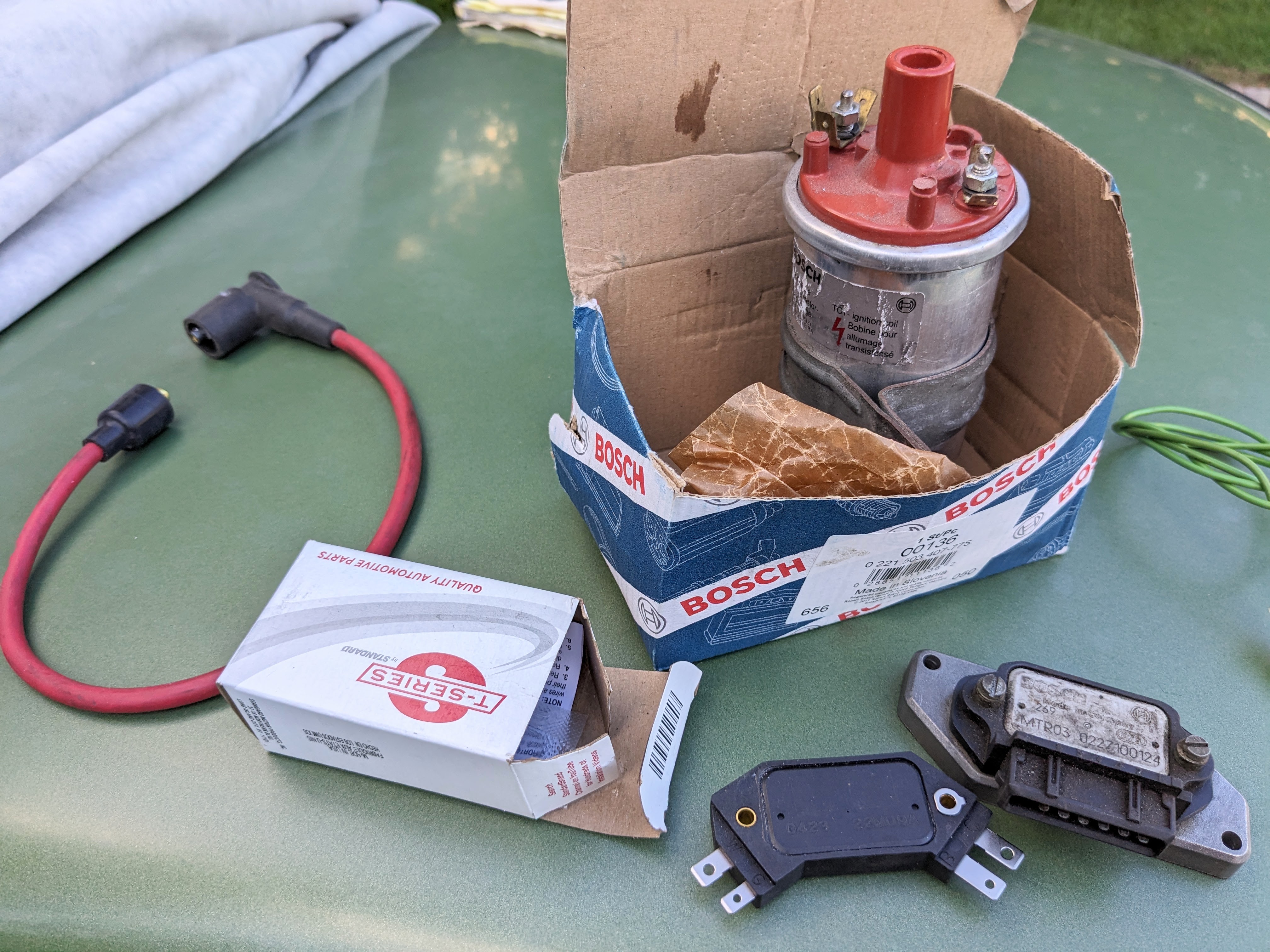
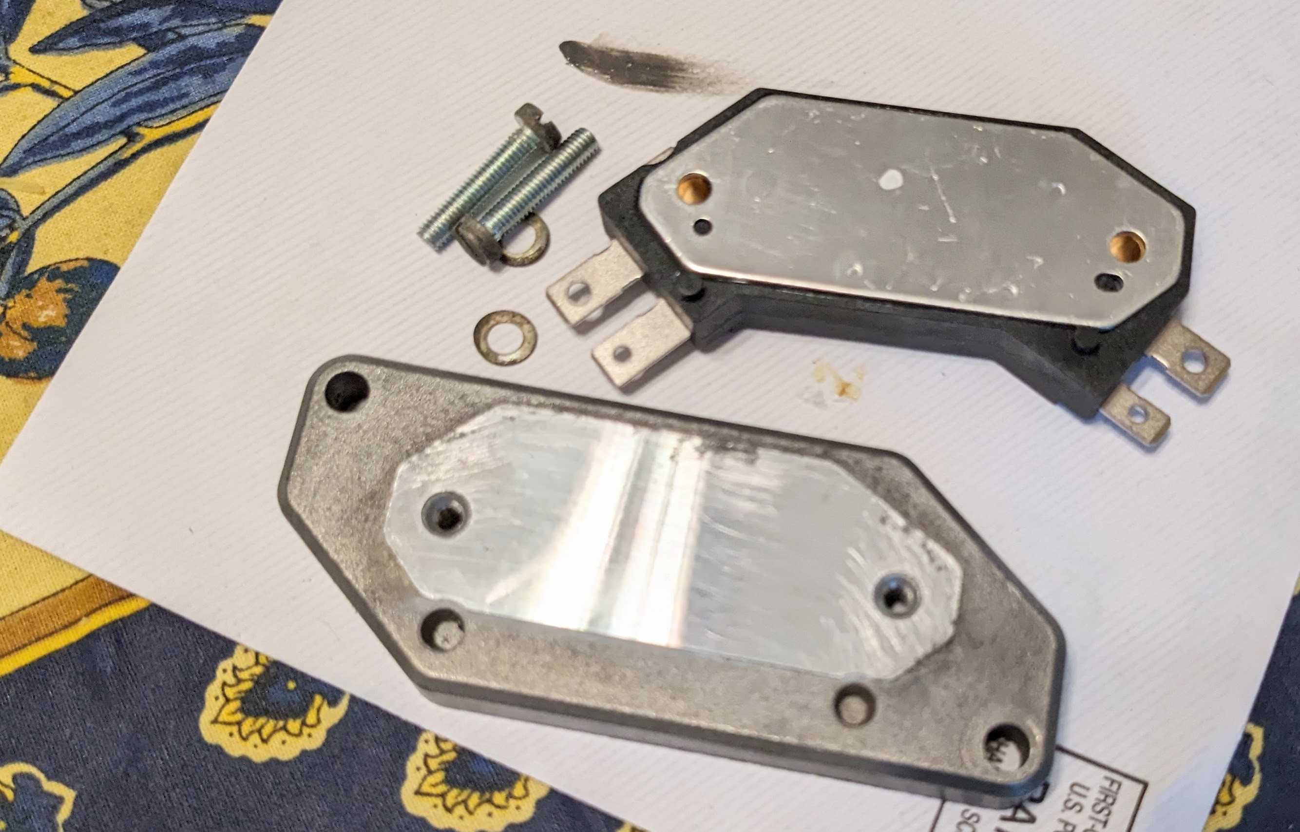
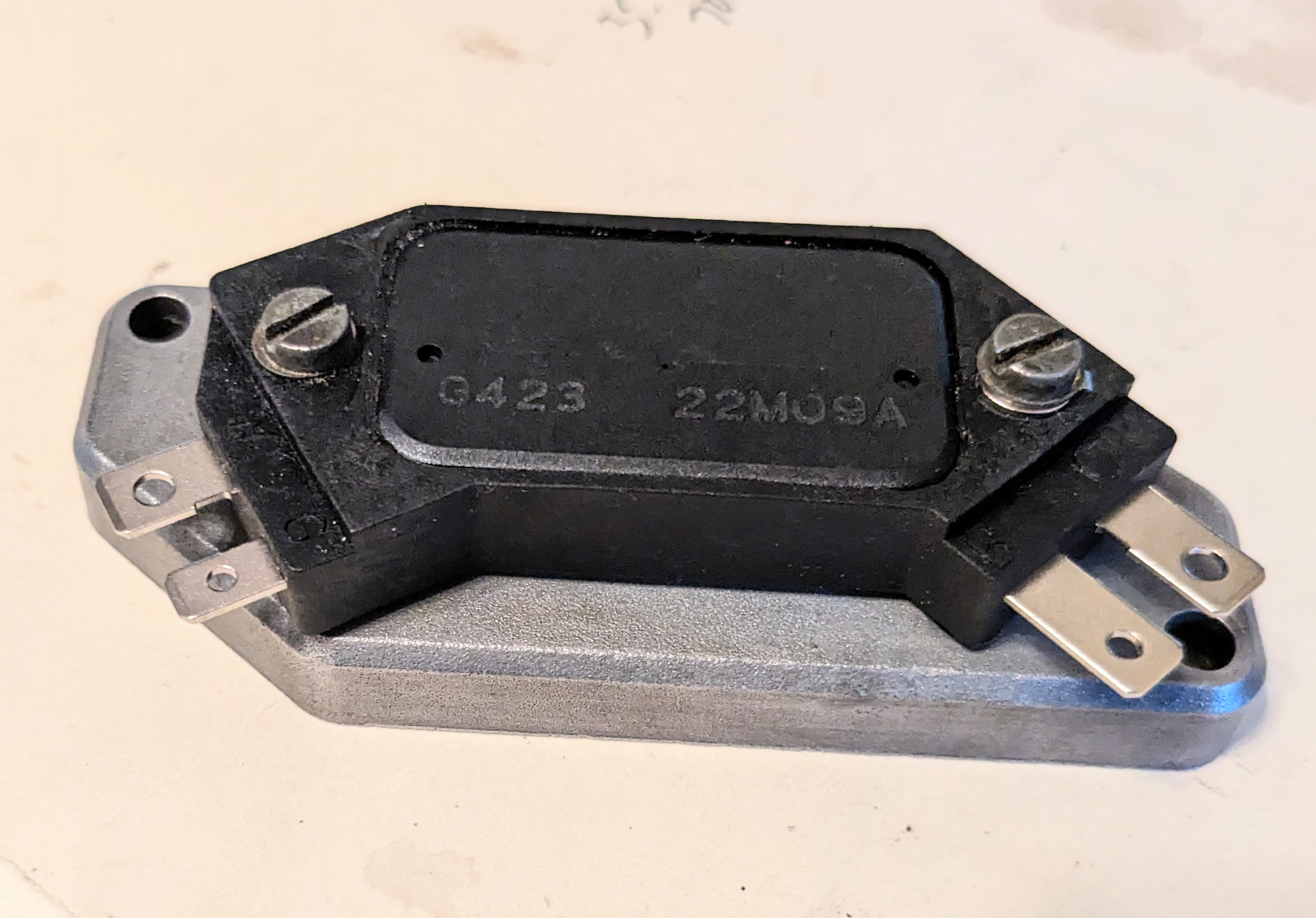
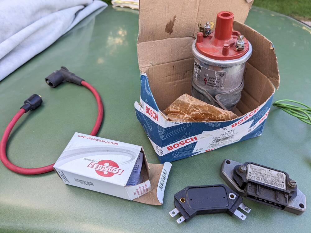
Bringing this back. I printed EuroDat's directions for reference. Honestly, the main reason for me to do this is to free up space - I need to add extra relays up under the dash, and the transistor ignition module is extremely bulky. I'm going to use a Bosch power stage heat sink as the form factor & pin locaters are identical, so it will occupy significantly less space than fitting the HEI inside the OEM box Volvo/Bosch coil for 90's model application. Different center post connection, however I already had Kingsborne wires made when I converted the ignition on my old X1/9, so the coil wire will work perfectly for the Z. Primary resistance value of this coil is in the ballpark suggested. Not a fan of aftermarket brand coils, so this will work for me. It would be even easier if a Bosch power stage could be used, since they are mounted in the bay with waterproof connection. SMP HEI Module & Bosch Heat Sink
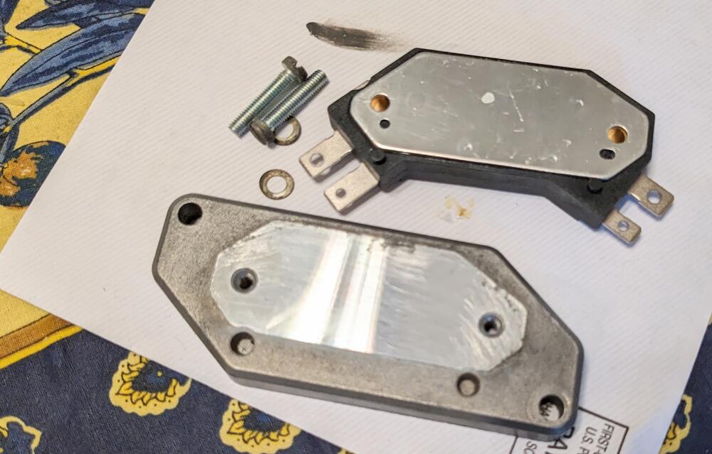
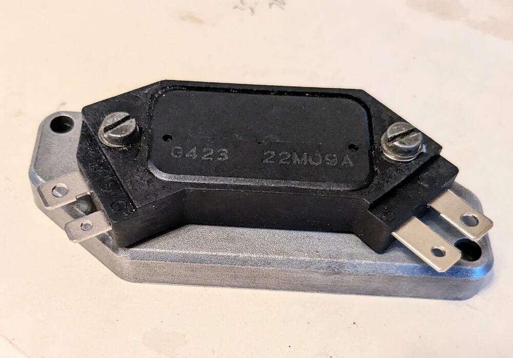
-
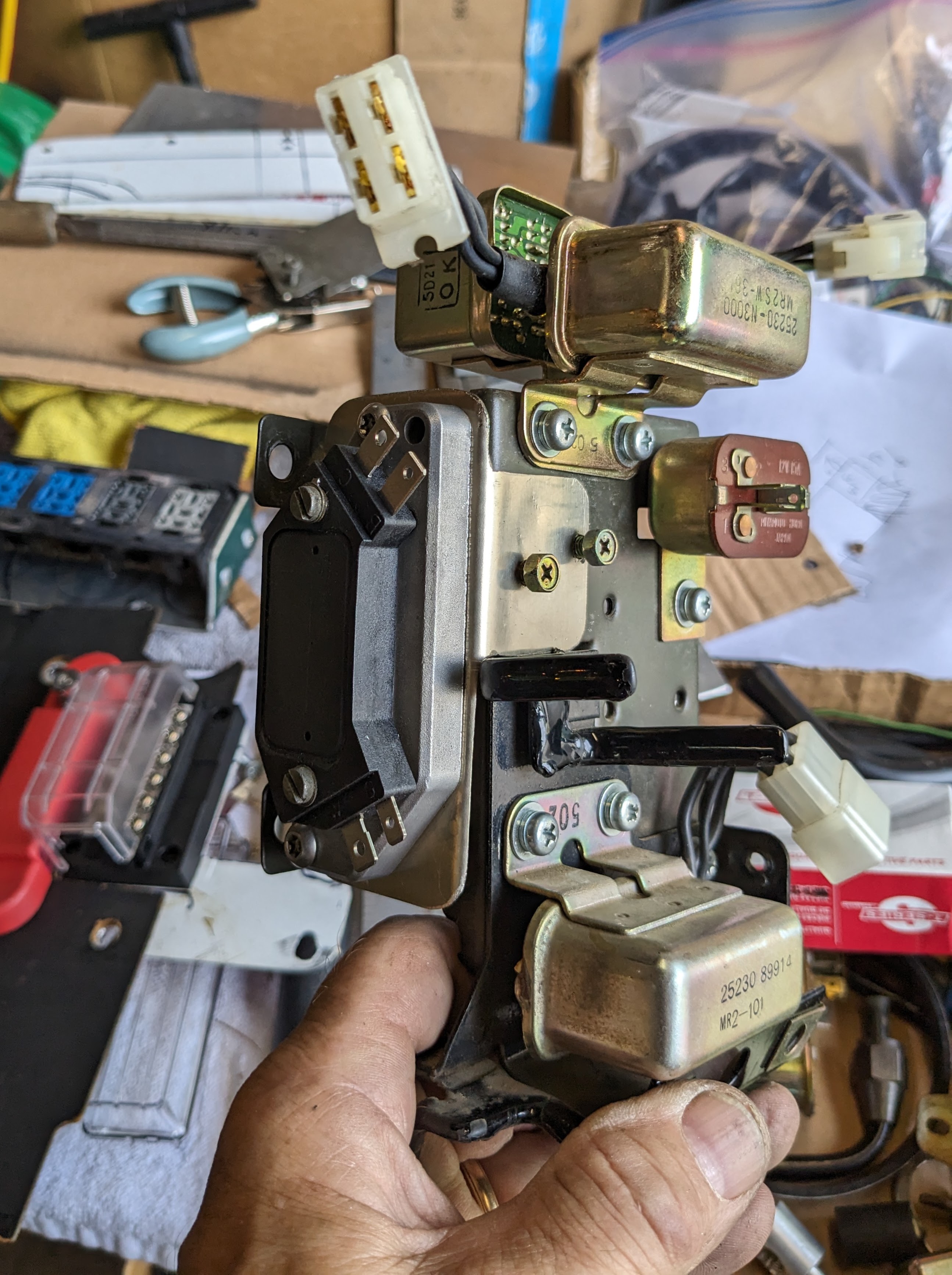
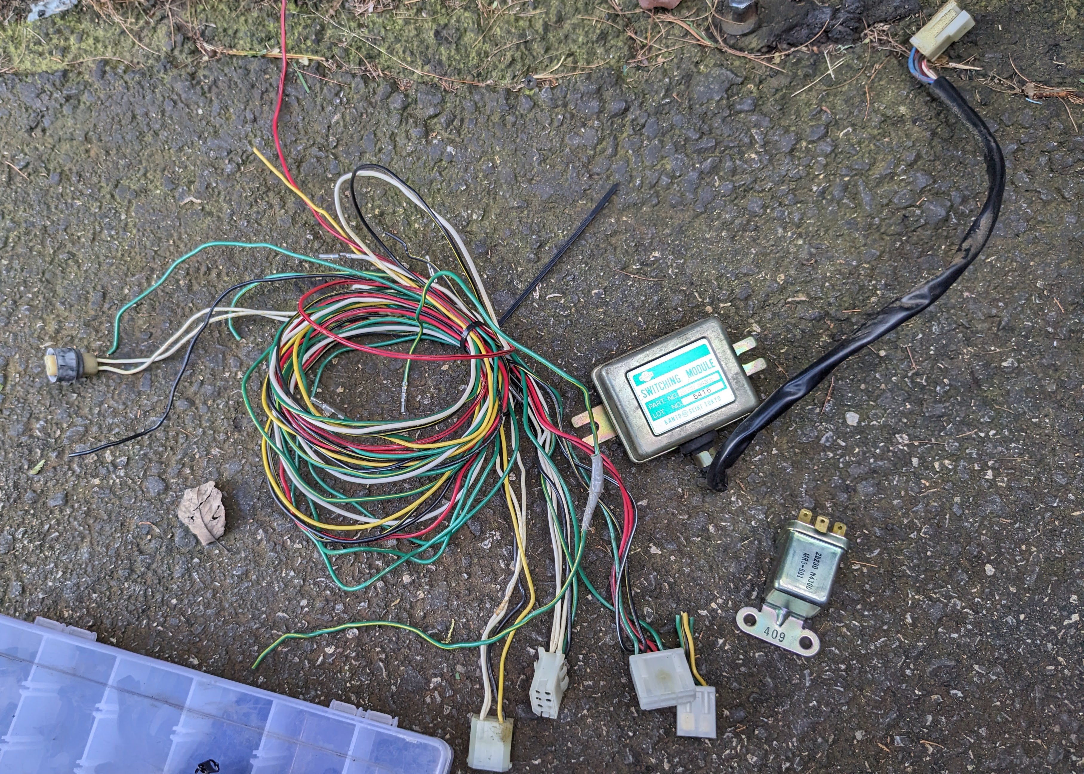
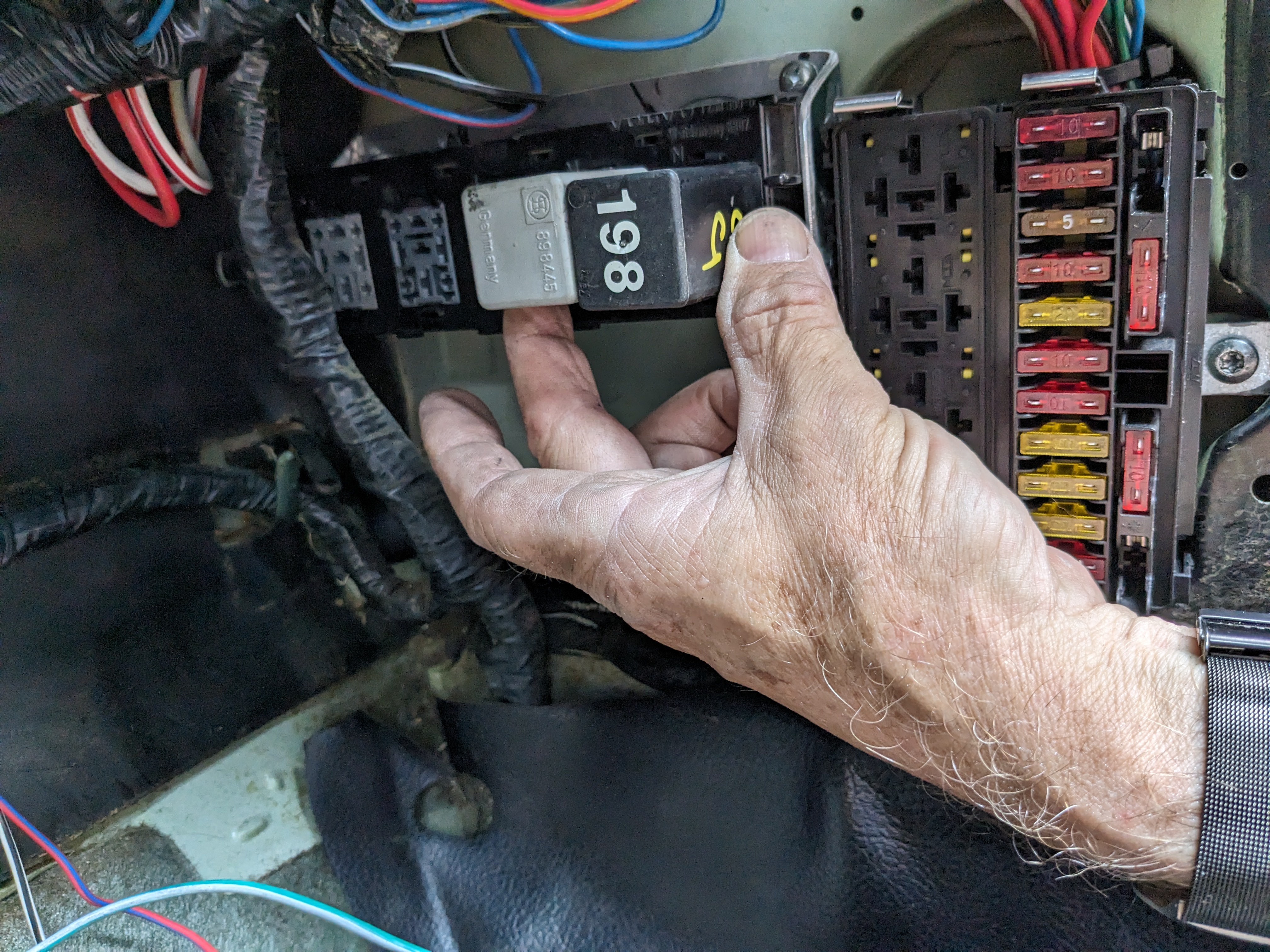
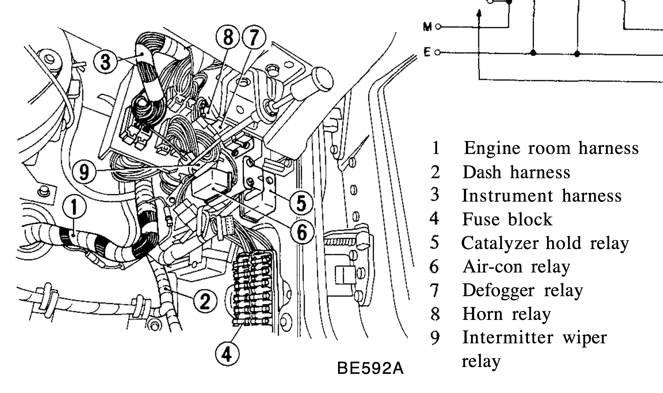
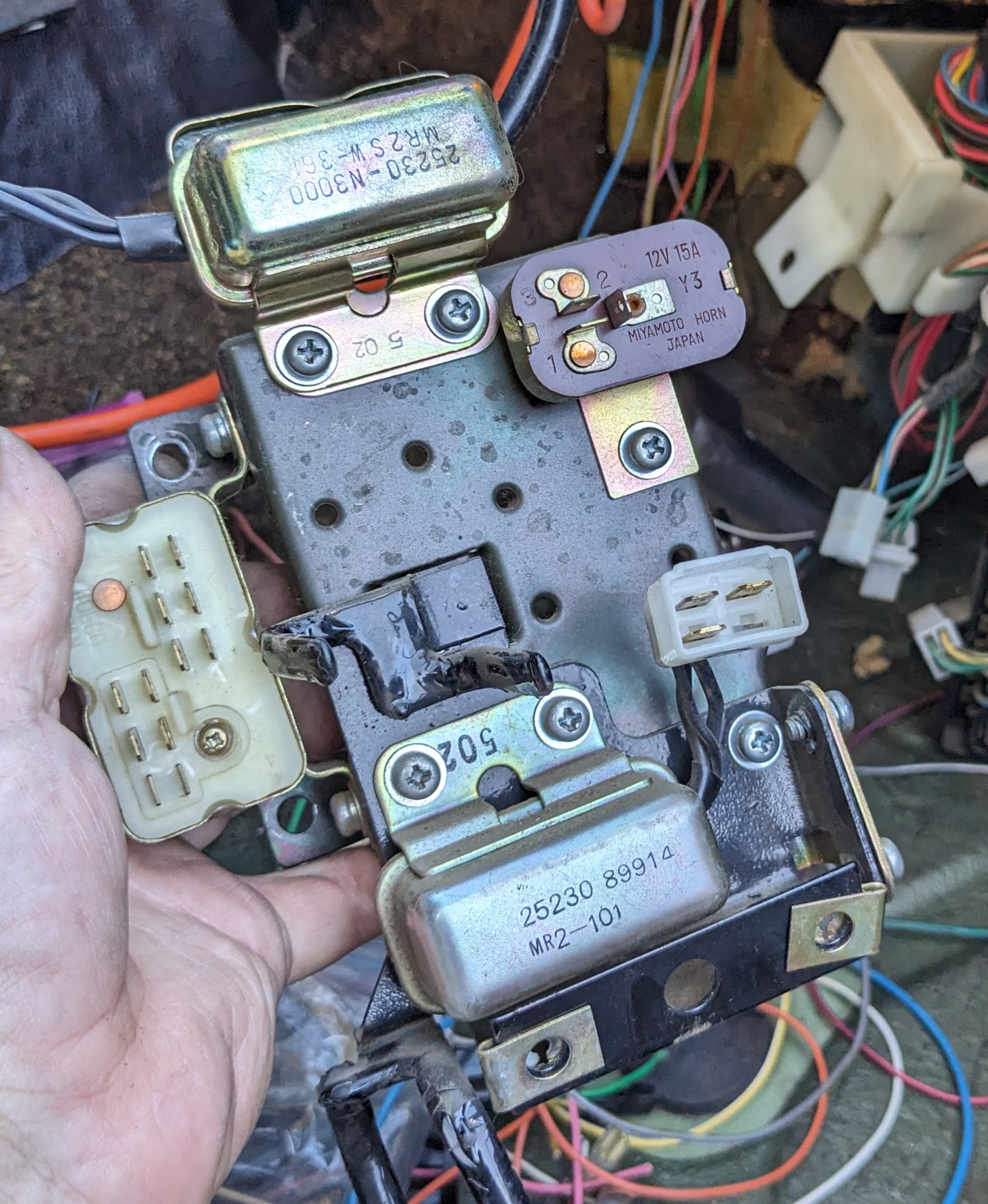
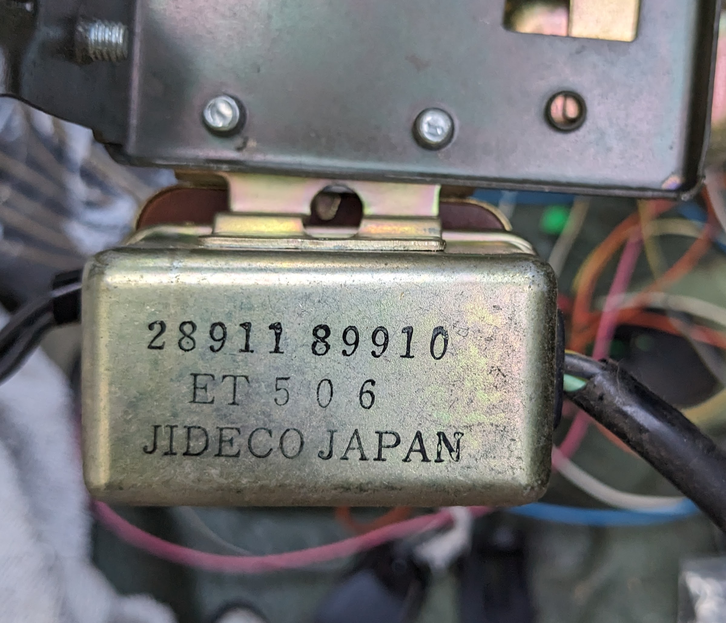
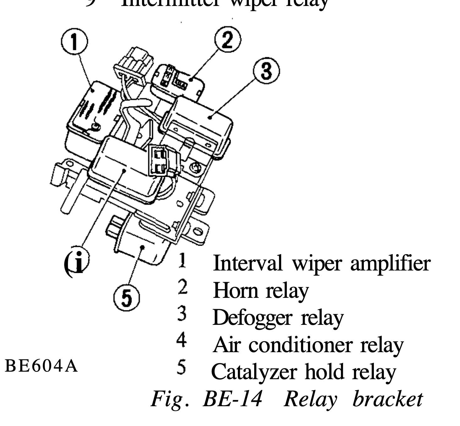
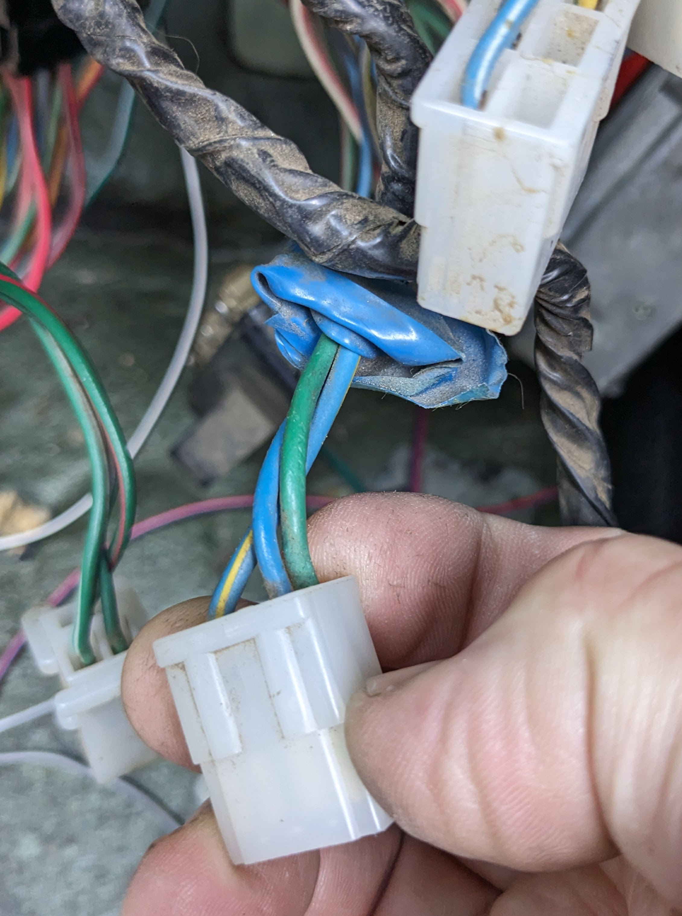
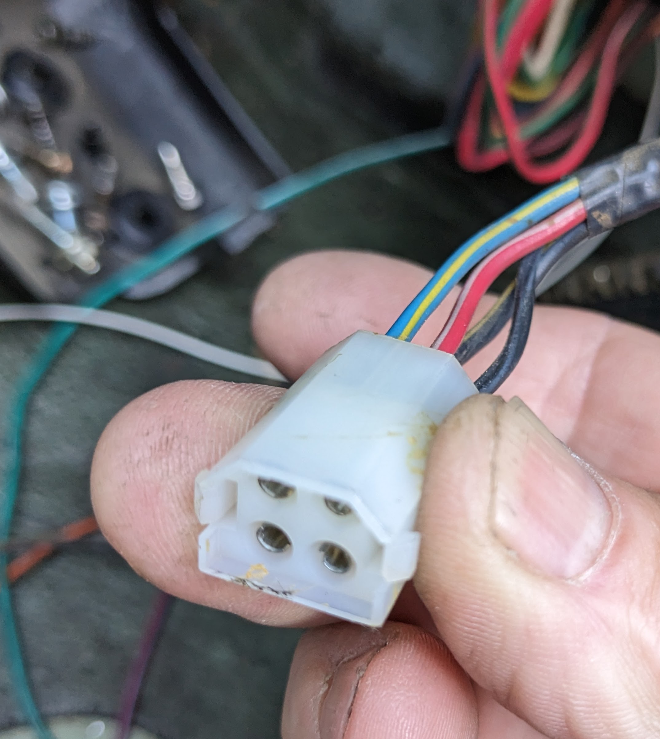
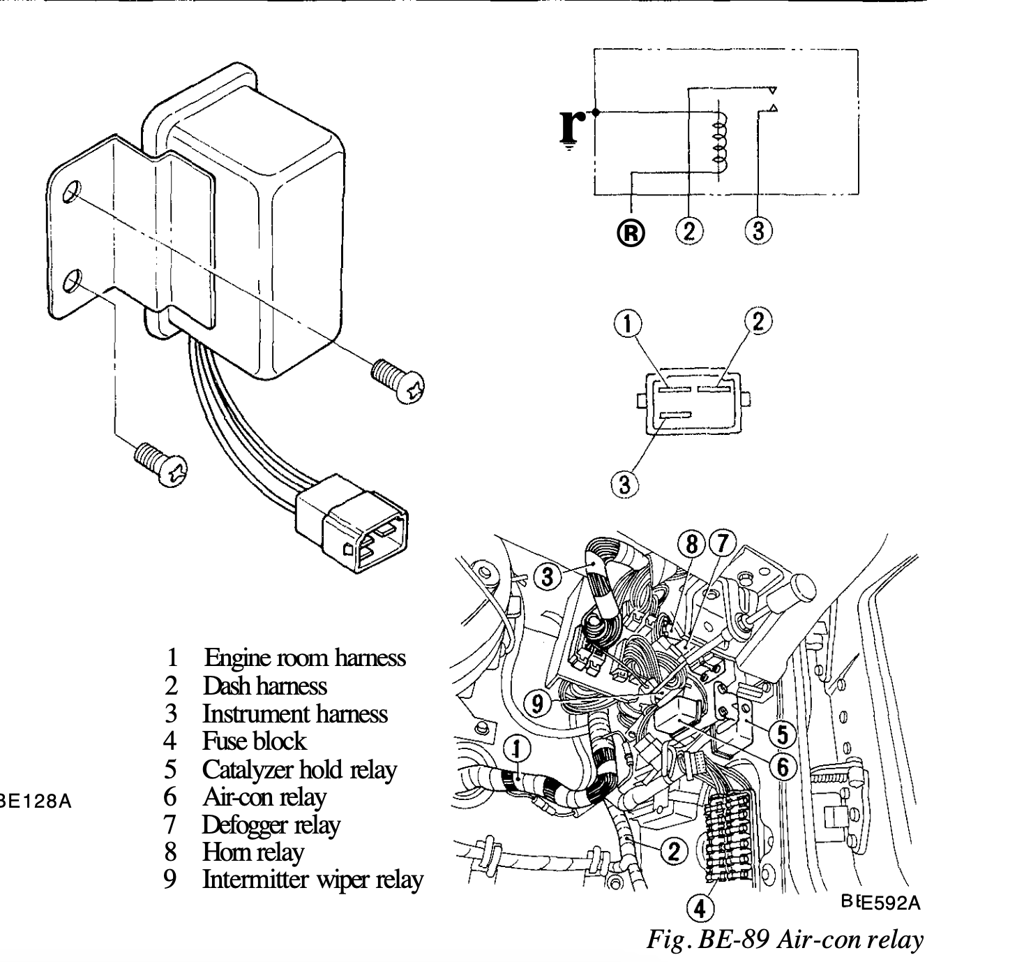
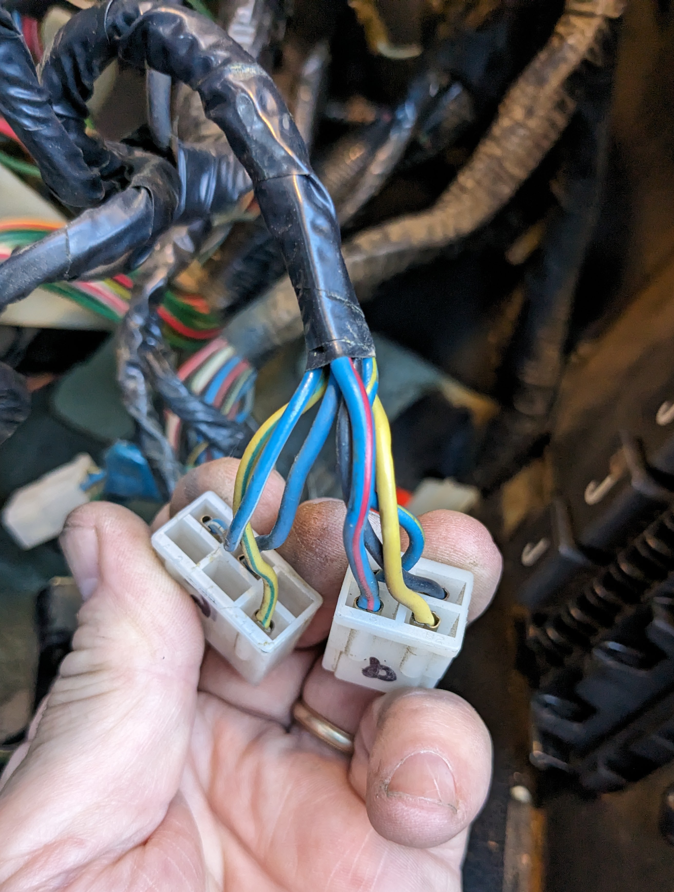
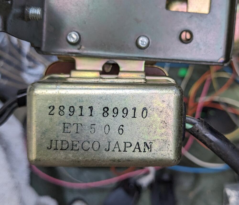
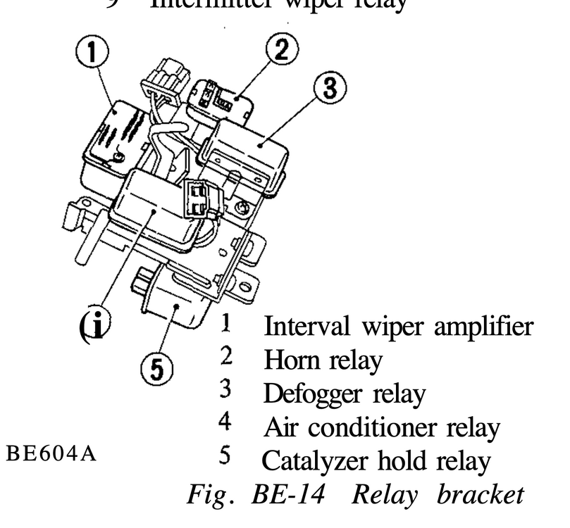
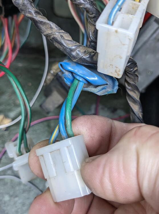
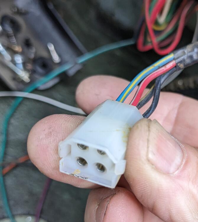
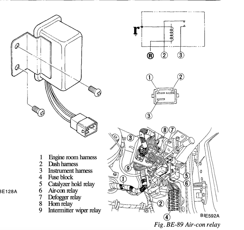
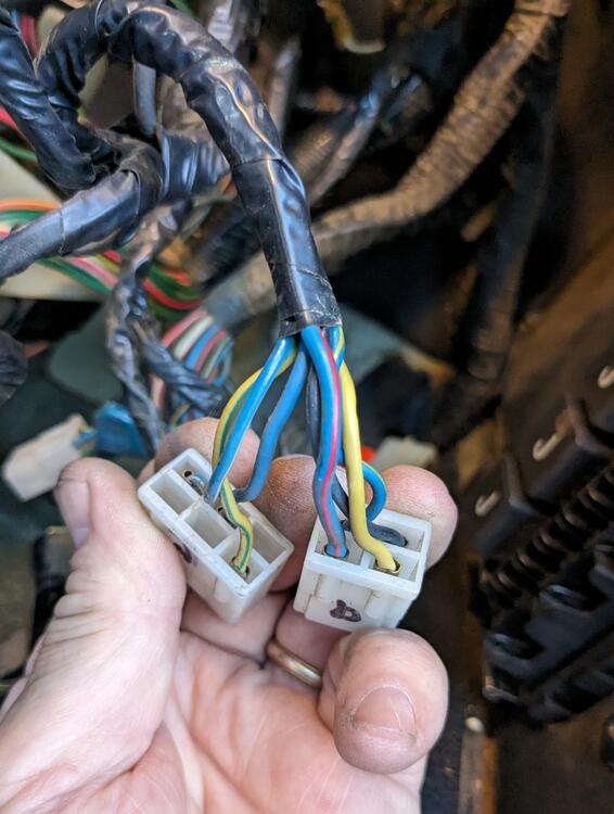
The relay diagram is somewhat confusing to deal with as a reference for what's actually there. Ultimately, the one that is unknown is the 25230-89914 relay The reality top: 25230-N3000 - should be Defrost relay top right: - Horn Relay Left: - Interval relay Bottom front: 25230-89914 ? Online says interval relay, diagram says AC relay, but mine didn't have factory AC Bottom right (back): Cat hold relay (not shown) Top middle (back): 28911-89910 Seat Belt Buzzer? Interval relay wiring doesn't match the schematic - shows 10 connections but - only 7 actual Harness side plug: Bl, Gn, Bl-Y backside, upper 28911 - 89910 harness side socket - Bl-Y, R-Wh, Blk, Blk-Y
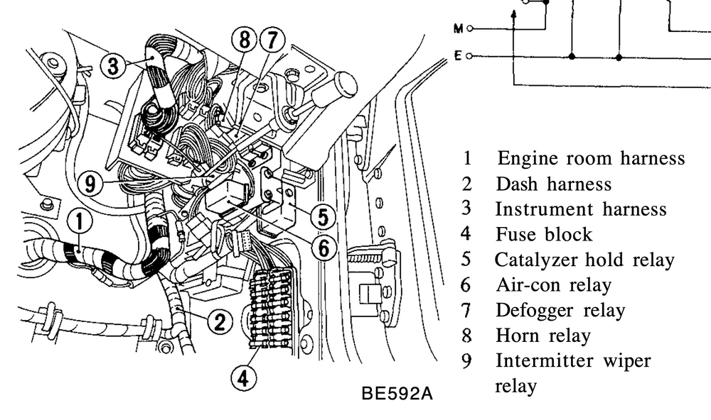
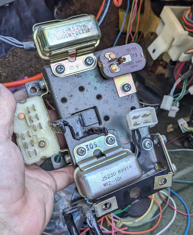
-
Took out the fusebox & relay panel yesterday as part of the re-wire/update, so It's time to revisit the wiper interval
-
I did look on Mouser, doesn't look like .22uf is available except surface mount. In any event, I've ordered a new OT multimeter that has the CAP feature. Should be here Friday, so I'll test the components I have.
-
Yeah, My OTC multimeters are from the 80's. I guess it may be time to invest in newer tech. 😄
-
I didn't test the new caps, I wouldn't have a clue how to even do that. I could swap them out for other new caps, but what I have is all from the same batch I bought off Amazon.
-
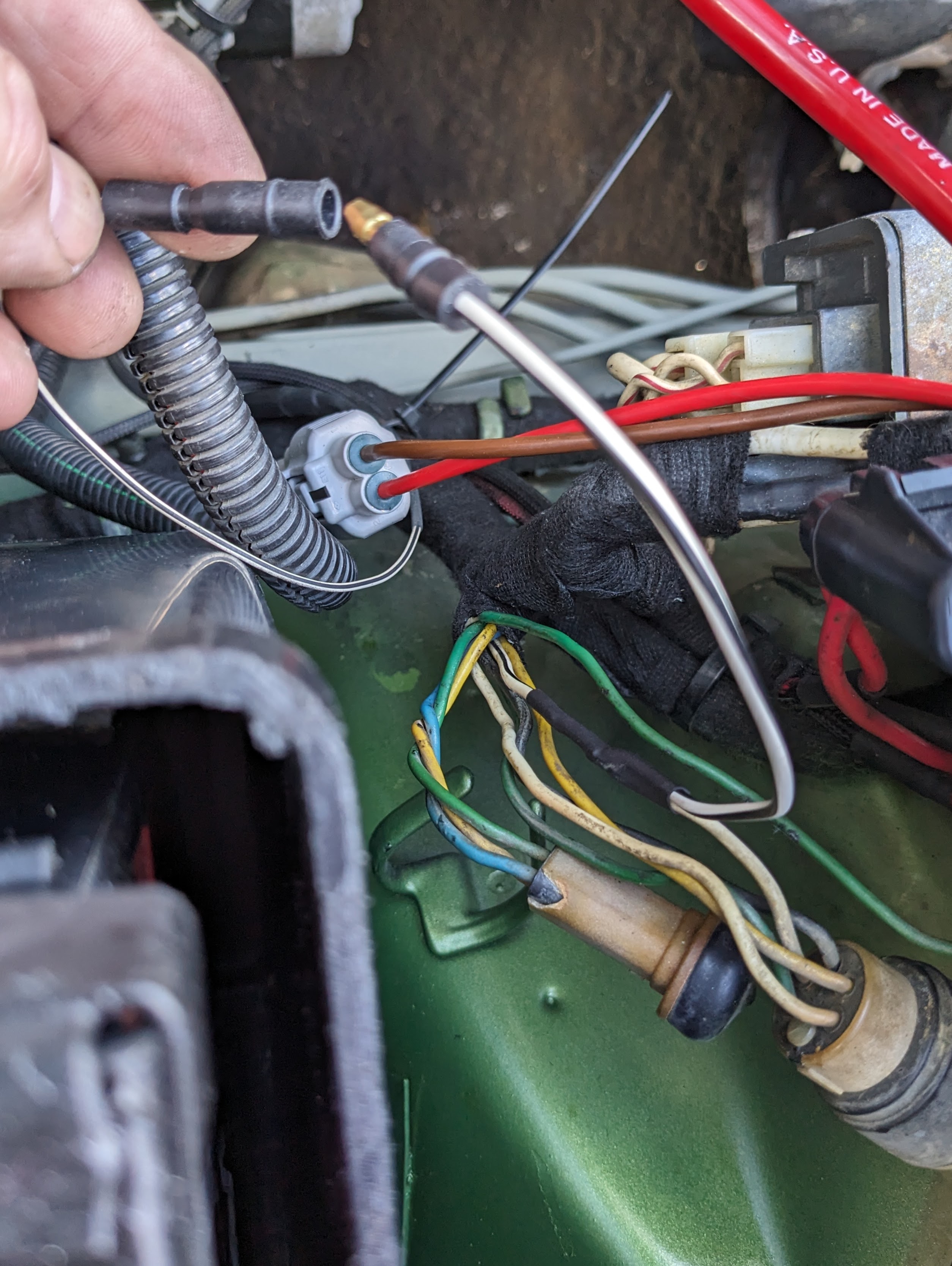
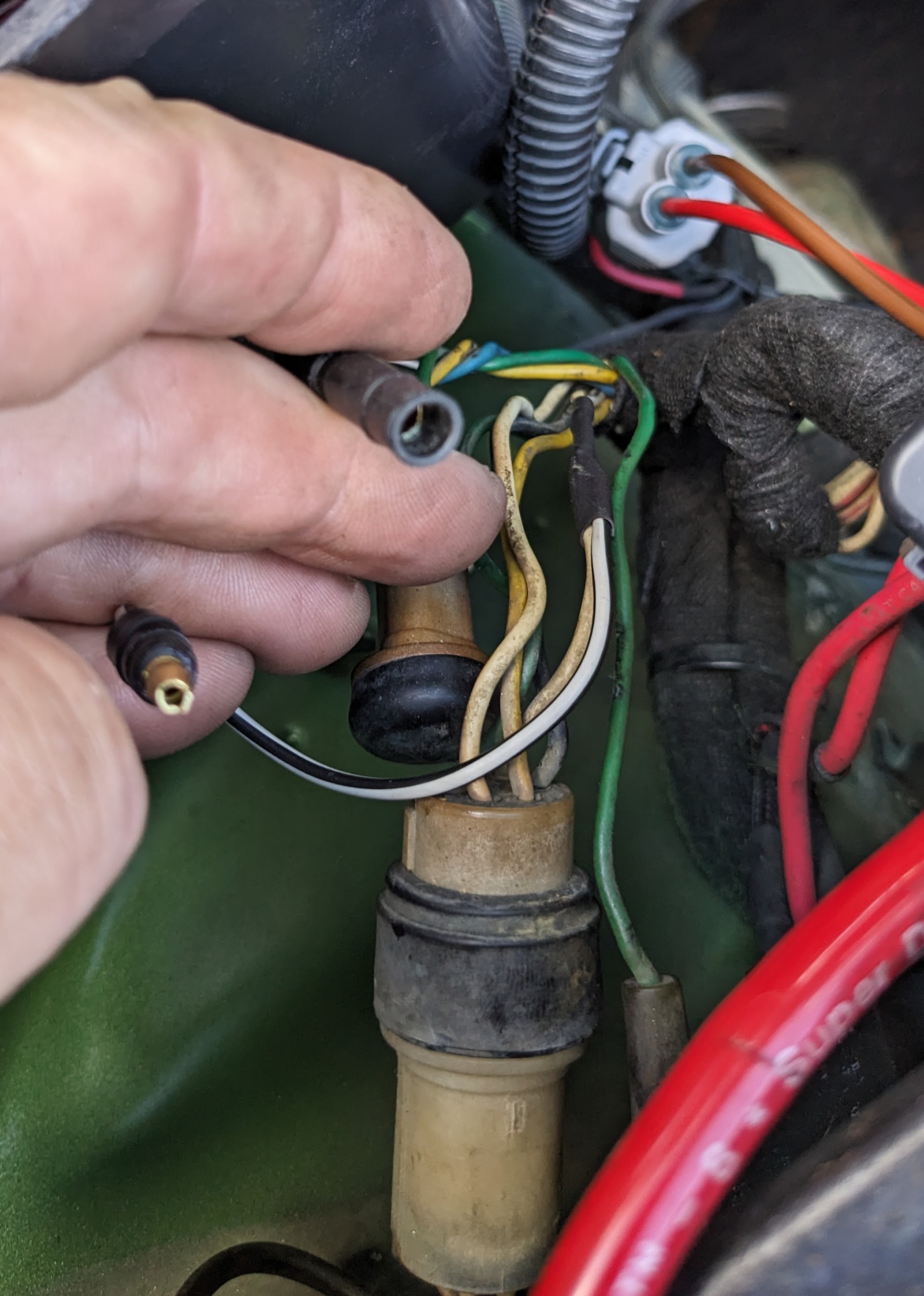
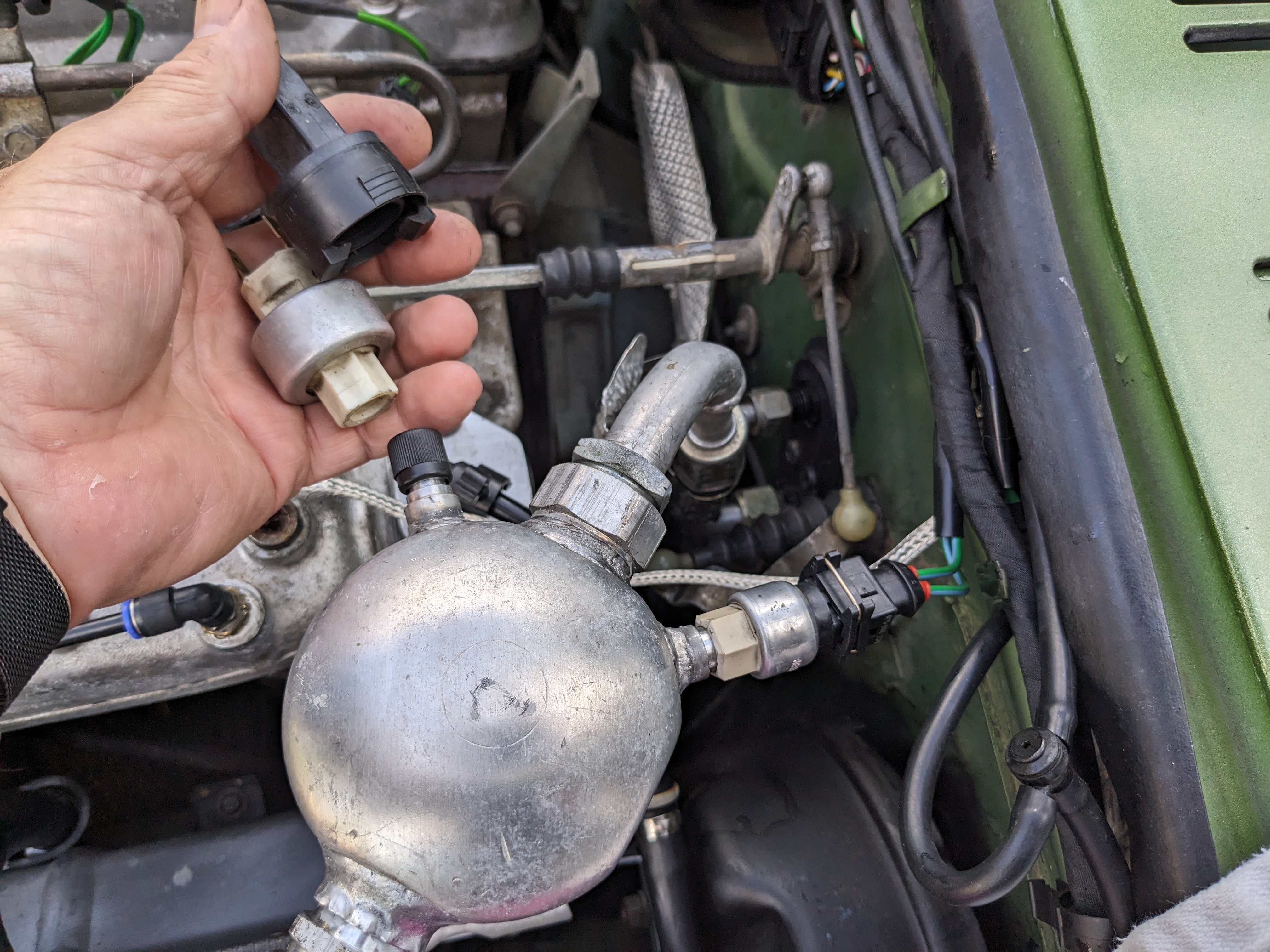
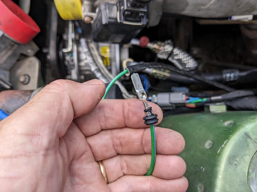
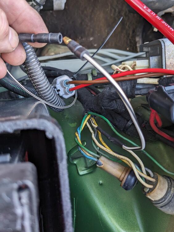
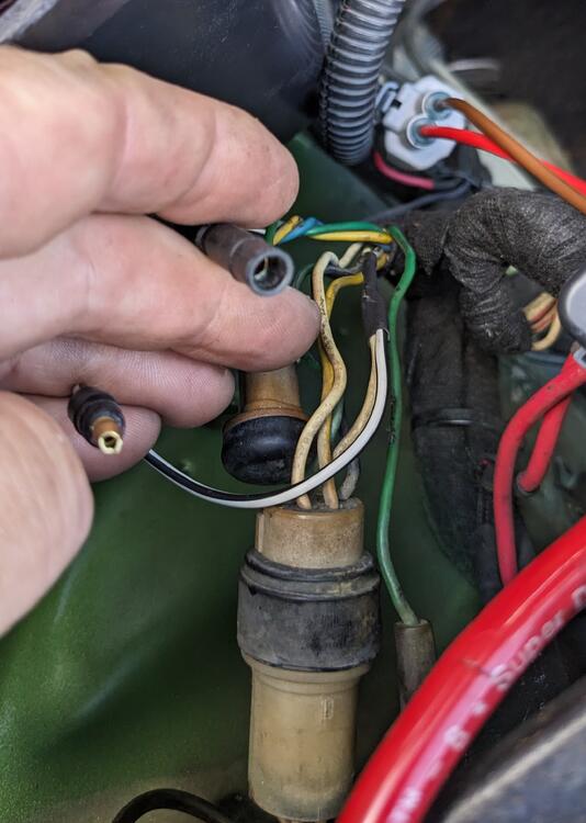
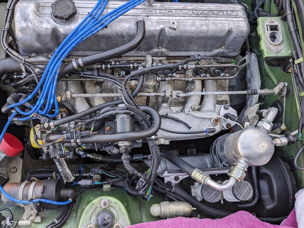
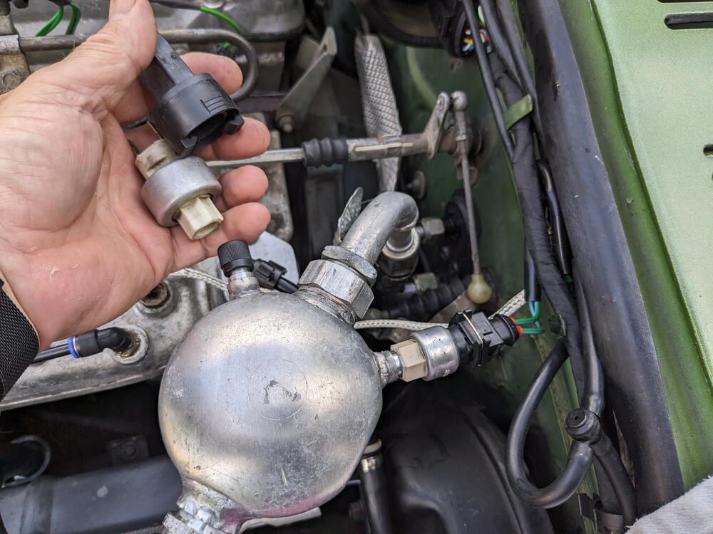
Wired the compressor & the delay relay signal from F at the V/reg swapped out the pressure switch
-
Thanks again for the functional description - it's nice to understand the sequence of events taking place on the board 🙂 I have some M- range resistors coming. If playing with that doesn't produce positive results, I think I'd just as soon buy a refurbished board from you.
-
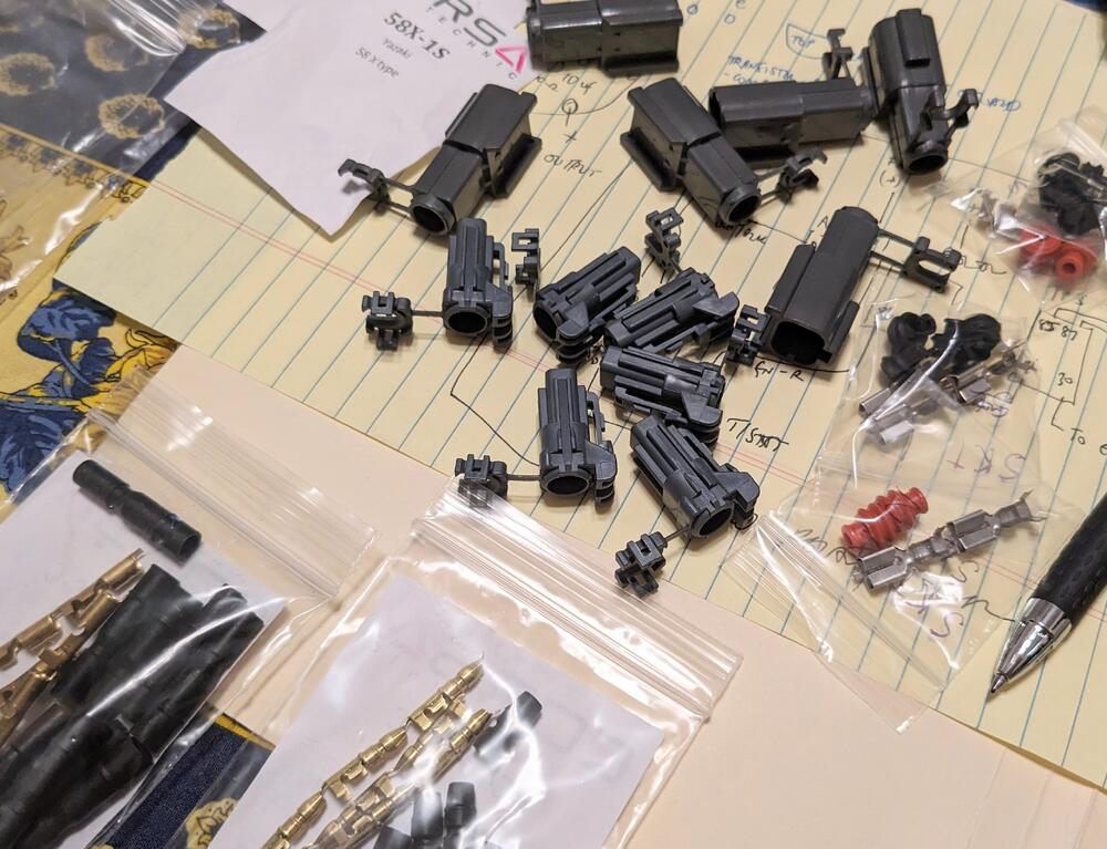
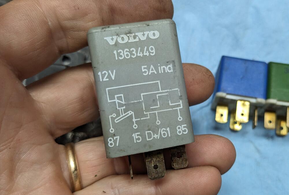
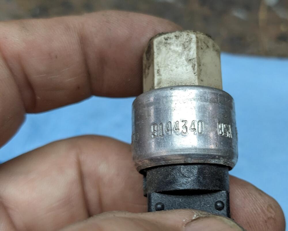
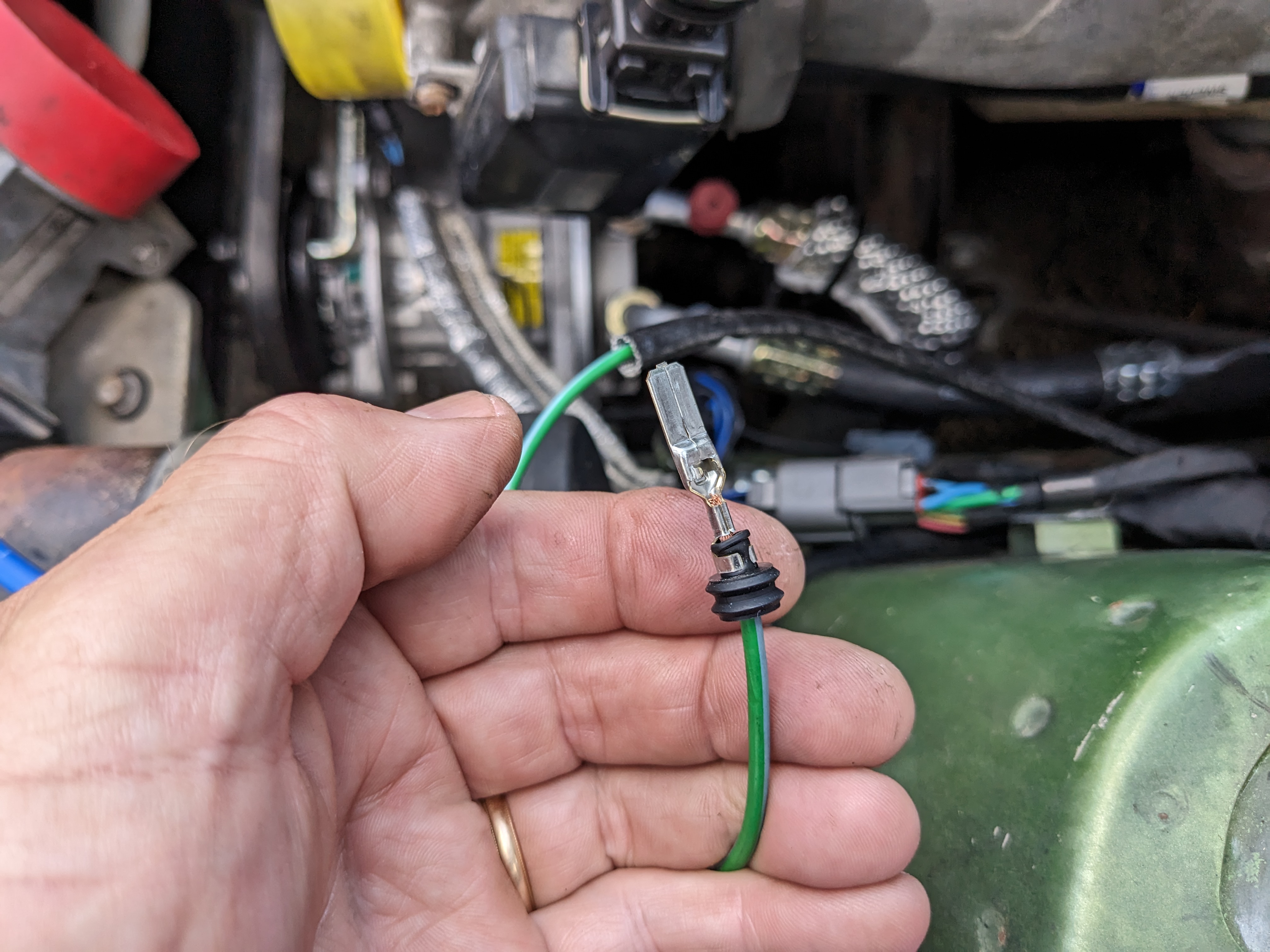
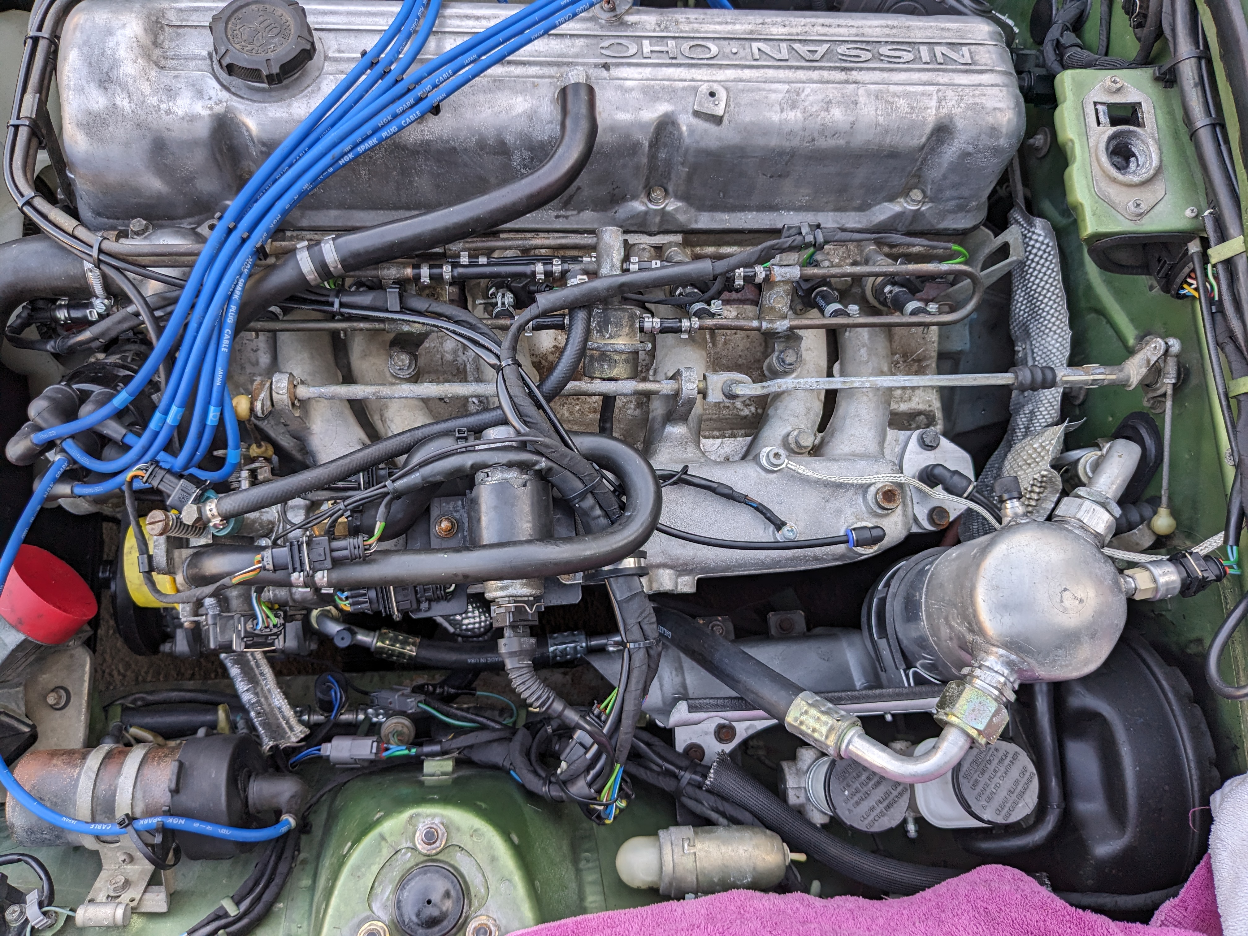
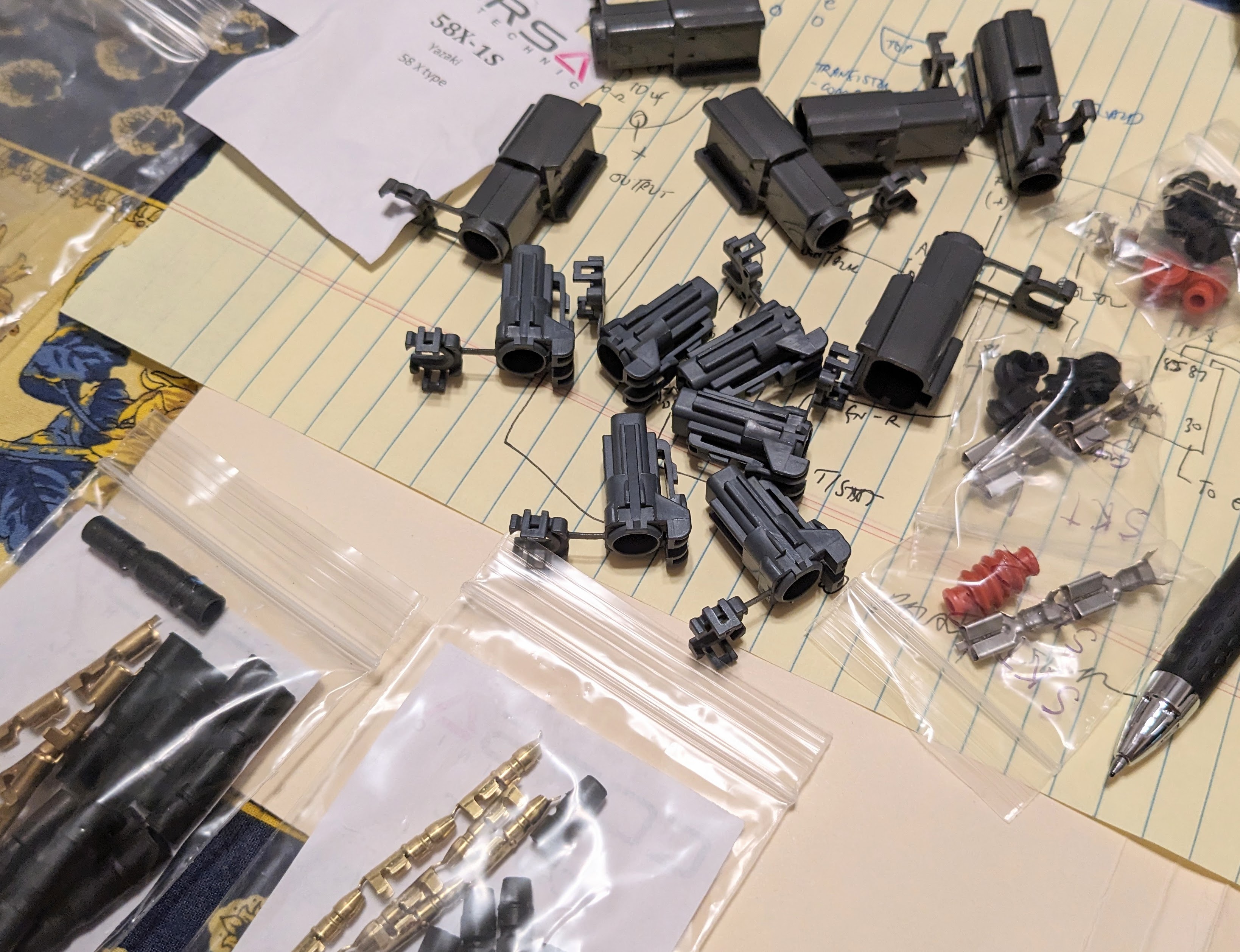
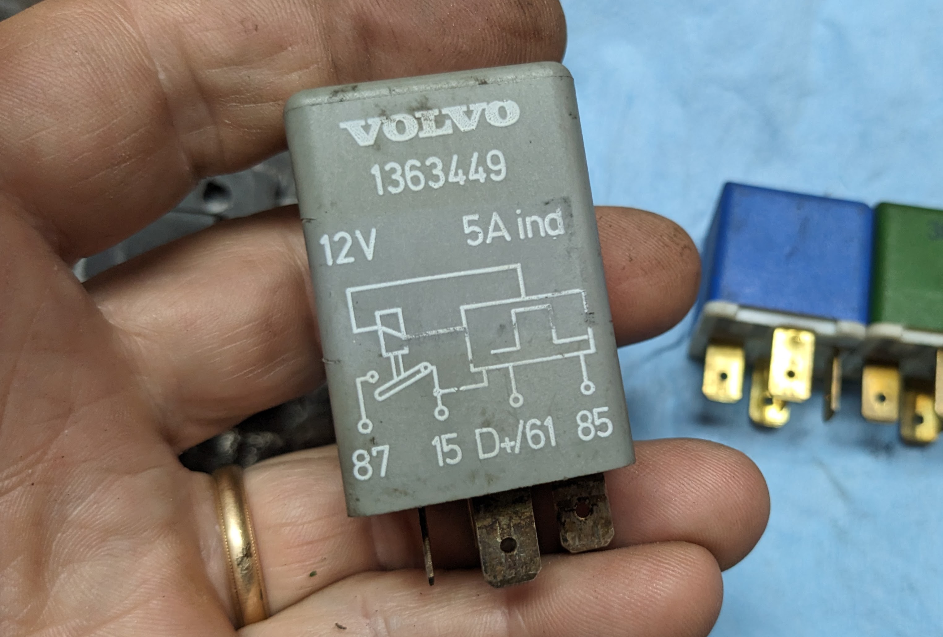
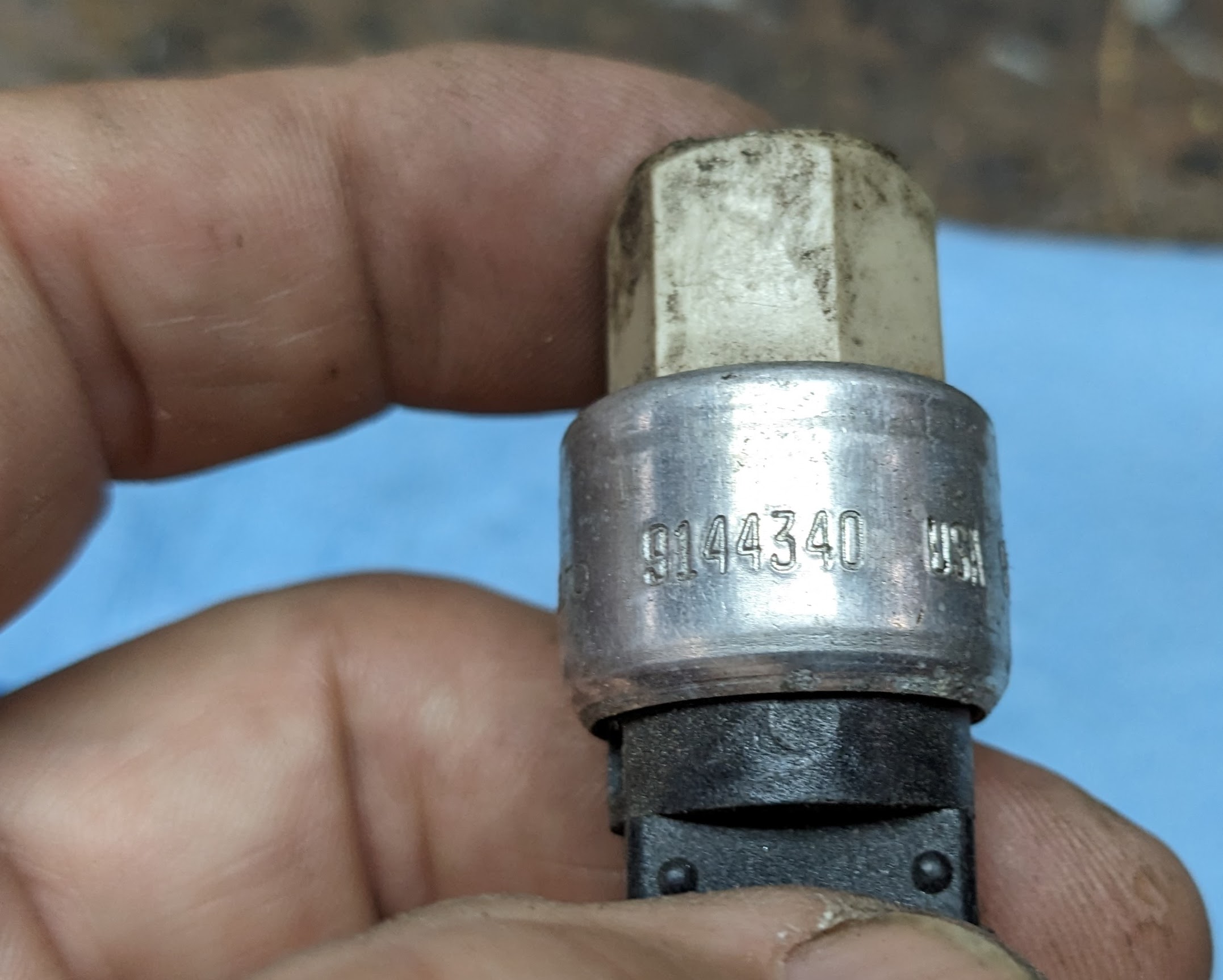
Haven't been able to work outside with all the rain. Just to keep things moving, I did a small amount of wiring inside the cabin - just the T/stat connections here, and routing wires for the delayed engagement relay VO 1363449. uses a sense signal from the alternator to only engage once the alternator is charging. The white/black wire to the V/reg (F terminal on alt) should be appropriate. Have a more compact low pressure switch that can go on the backside of the Accumulator facing the firewall, instead of the sticking out over the manifold VO 9144340 a bought a number of single pole waterproof connectors, so the bullet style will work for the D+ splice at the v/reg 6 pole connector, and at the AC compressor.