


Captain Obvious
Community Member
-
Joined
-
Last visited
Everything posted by Captain Obvious
-
That means "Don't cut off the staked in portion before taking the nut off. Just put a big enough wrench on it and spin the nut off. The staked over portion (caulking) will bend out of the way as the nut comes off." That's what they meant, but don't believe it. People have done that and it messes up the threads. Not sure why they recommended that. Maybe they thought it was less risky than trying to cut off the staked over section and accidently cutting into the threaded portion? In any event, even though they said to leave the caulking in place... Don't.
-
Yeah, then yours probably petrified and fell off some time in the past. And for the guys with the O-ring style built into the valve cover, I guess that's the older style. according to the documentation, they changed over to the newer style in 71.
-
I was only worried about elbows down, and I washed thoroughly with dishwashing soap* in the sink shortly after the event. I heard some long time ago that you have about 45 minutes minimum to get that stuff off your skin and you should be OK. It was about thirty minutes before I got washed up, and with no issues today, I think I'm fine. The only thing bothering me now is my thumb is still swollen and hurts way more than it should from such a small wound. I think I broke the tip of a thorn off inside. Here, have some roses they said. They're beautiful, they said. Haha!! *We usually use Dawn, but couldn't get it last time we needed soap, so we're currently using Palmolive.
-
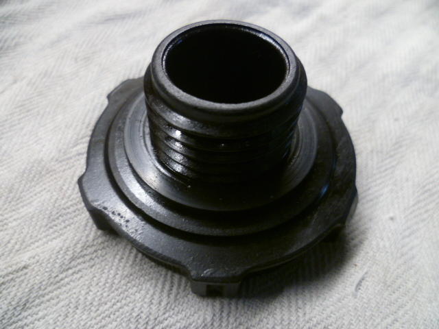
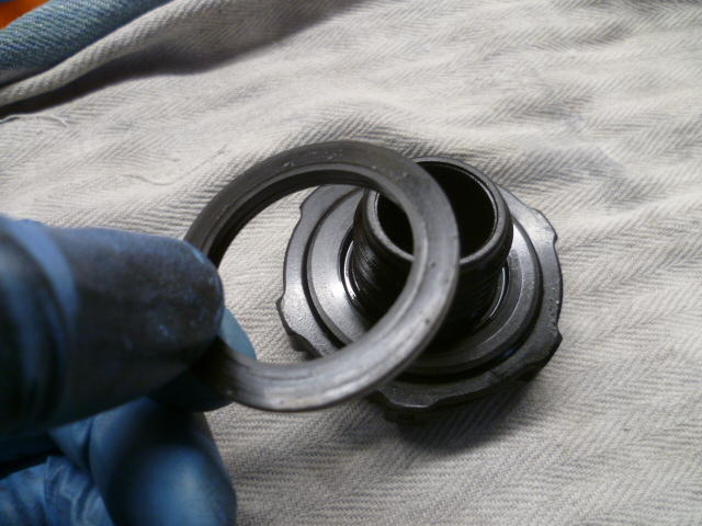
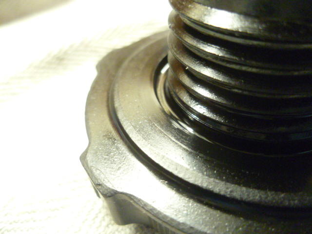
Right. It's easy to mistake it for part of the cap. Here's some pics. Cap, as it's normally seen: Close up of the seal in-situ. Looks like all one piece: But in fact, it's not. Used a thin blade to get a little separation and get things started, and the seal comes off. Note the step on the seal and the recess on the cap. Speculation on my part, but I bet the earlier seals (with the different part number) didn't have that feature: And here's a close-up of the cap with the seal removed. You can see the recessed area for the step.


-
I have one on my cap. It's a black washer and if you poke at it with a screwdriver tip you can see that it's not quite as hard as the plastic cap, but it's pretty hard. Maybe 1/16 inch thick? ID is a snug fit on the threads, and the OD is about the same size as the raised boss on the valve cover? I don't know how compliant they were when new so I don't know if it was always that hard, but I suspect it was slightly more compliant years ago. Every Z I've messed with has had one. I think you might just be not realizing it's there. It's really easy to mistake it for "part of the cap". I'll take a pic tomorrow if someone doesn't beat me to it.
-
Gotcha on wanting to keep the engine together for now. I'm continuing to work on the nut as time allows. I spent almost all of today outside trying to injure myself with lawn and garden equipment. Couple minor flesh wounds. Won't know about poison ivy until tomorrow.
-
Thinking about it a little more, there is also the possibility that yours got so completely petrified that it cracked into pieces and fell off sometime in the past.
-
Yes there should be a seal on the cap, and I bet you DO have one there. It's just hard as a rock from heat and age and it looks and feels like it's hard plastic and part of the cap. But in fact, it's a separate piece. #40 GASKET-OIL FILLER CAP - 15270-78500 Note that the early cars (through mid-71) used a different number, but from that point on, everything used the 15270-78500.
-
Oh, and after I see that busted damper, I'm thinking that the more meat I leave on the "nut" the better. In fact, how about I skip the flats completely and you just weld a pipe to it? I'm concerned that maybe your adjustable will smear the flats. It's currently a little over 3" OD and maybe 3/4 thick hockey puck. Very thick walls at this point. The weak point is probably shearing the key off.
-
As I continue to work on the crank nut as I get the chance... Some questions. Do the motors still have the oil pans on them? The reason I ask is that if the do, the insides are maybe less rusty than the top sides? And the reason that may be interesting is that it may be easier to push a piston DOWN rather than up. I'm thinking there's no reason you couldn't pull the crank and try to tap the pistons in the downward direction is there? Block of wood covering the entire piston face (for protection and force spreading) and a hammer? Thinking that if you could move them into a clean spot. Or do you think they were maybe heat seized and have rings welded to bores? Reason I ask THAT is because if that's the case, you'll need to get the block bored and the old pistons won't work anyway. Might just crack them and pull out the pieces? Anyway, just thinking of other alternatives in parallel of me working on that nut.
-
Awesome. So while you were in there messing around, did you peek inside the brake booster and verify that it is clean and dry? It hasn't sucked in any brake fluid in the past, right?
-
Derek, That gives me a thought... Instead of spending time on the nut portion of the equation, how about spending it on the TOOL portion. Build a chain wrench designed to grab the teeth on the crank sprocket. Like this, but designed using a length of two row Nissan timing chain: That'll be a project for the next guy...
-
Thanks much for the offer! I'll keep in mind.
-
I said wrench, not "wench". Thanks for the data. I'll make sure my opposing flats are within that range. I had already started aiming at 2", but since your wrench will go bigger, I might too. Less metal to remove.
-
So about these two opposing flats... How wide does your wrench open?
-
Creative thinking, but having the shaper (and hopefully a broach close to what I need?) I don't think it would save me much. I'd still have to put the slot in the inner piece and for that, I'd use the shaper. Would be a little easier since I could do it as an external operation instead of internal, but not enough to warrant two pieces and welding. I'm not stifling the creativity though! Certainly a way to make use of the tools you have to accomplish the task in a different way. And I like your pic a lot. I wish I had a CAD package I could use to whip up stuff like that! I'm still drawing by hand! LOL!
-
Cool. I've never owned one, but I've driven one. Fun cars.
-
.100 deep it shall be. And two flats.
-
Broaching would certainly be the fastest and easiest. The problem, however, is that I don't have a broach that width. I know I have 1/4 (.250), and I think I have 3/16 (.1875), but I'm positive I don't have .205 I'm thinking I might broach to 3/16 and then finalize the width of the slot on the shaper. That would be a lot faster than hogging all of it out on the shaper. So to answer your question... I haven't completely decided yet? Haha!!
-
Welcome to the club! Flat tops rule! Is that your 2002 as well?
-
I don't like the whole "shared hold down" thing between intake and exhaust. It's what we got, but I just wish they hadn't done that. Hopefully Pacesetter can hook you up.
-
So I found a chunk of stock that would probably work for a crank nut. It's not as thick as I would have liked, but it's what I got. However, before I got too deep into it, I wanted to verify measurements: I'm going to make the ID to be a slip fit over a 1.378 shaft. Couple thousandths over. You had previously mentioned that the key is .205 wide? I'm thinking "as long as the slot is wide enough that the device fits over the key, it will work". The goal would be to keep the amount of slop to a minimum, but since you're just using it to turn the crank, it really doesn't matter. There could be 5 degrees of slop and it would still work, right? I'm thinking you'll want to rock the force back and forth to get the motor unstuck, so slop like that would be "uncomfortable and feel cheap", but it would still work. So how about the DEPTH of the slot? How far out of the crank does the key stick up? And we already talked a little about the flats on the outside for using a wrench. Would just two flats on opposing sides work for your BFA? That would be the easiest to make. Square would be second easiest. And I could do hex, but it's just more work.
-
Here's another thread for some input: https://www.classiczcars.com/forums/topic/62535-thick-manifold-washers-notched-wanted/
-
Wow. Me neither!! Hope those find good homes.
-
Glad to help. I'll take a look at what I have for raw materials around here and let you know.


