Zed Head
Free Member
-
Joined
-
Last visited
Everything posted by Zed Head
-
 I know that the wheel cylinders are different from early to late. I have 78 rear brakes on my 76. I'd guess that the location of the hole is different. Can't remember for sure on the hole, but I'm certain the cylinders are different. Single piston, sliding, versus double piston. I also had to replace a line for the same reason, but I bent my own using a prefitted straight line from OReilly, and a board and some long wood screws as a bending fixture. Just set the old line on the board and drive screws in at the bending points. Then lay the new line in and bend it to fit the curve. I measured the length of straight line I needed with a piece of string. It wasn't difficult and actually kind of enjoyable. A tip on getting the old fitting out, if you haven't - file new parallel flats on the nut and clamp a good pair of clean-jawed Vise-Grips on it. If the problem nut is at the junction you can apply heat without too much concern. It's all metal. If it's at the cylinder, just spend a lot of time getting the grip tight on the nut. If it starts to slip, stop and start over. It will snap loose like it's breaking but won't .
 -
-
Toyota put the starter for their V8 Tundra engines under the intake manifold. And gave them poor copper contacts in the solenoid. A friend of mine has starting dread every day now, but doesn't want to spend the money to have it fixed and isn't a car guy. I offered to help him fix it but he's just going to live with it until he gets stuck somewhere.
-
I would go directly to the fuel pump relay. The ignition switch powers the ignition relay, and it everything else is working then your ignition switch is fine. Click on your user name, upper right corner of page, and a drop-down menu will open up.
-
I think that's a drain hole for oil. So bottom would be proper in that case. I measured 39.1 mm for that spring. 1.54 inches.The screw, #27, has a nice divot inside for a ball bearing if you wanted to try the preloading. I think that the original design is just meant for easy shifting. I'm going to try a preload if I can get mine out next time I'm under the car. It will put more pressure on #25, which sits on a ramp on the shaft. Should center itself more forcefully.
-
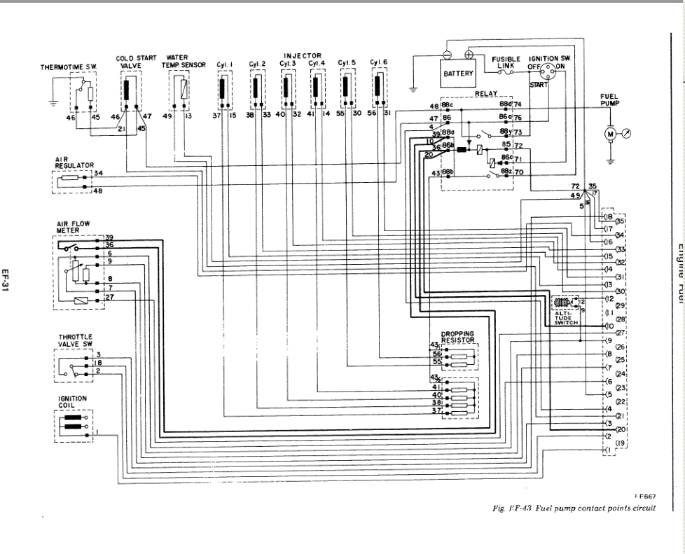
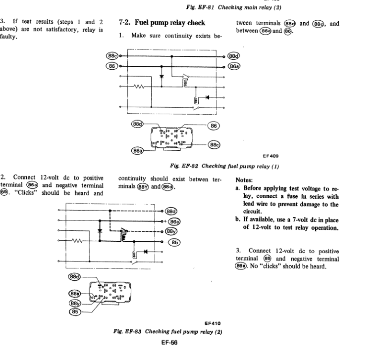
Actually, I'm just suggesting that you not worry about why installing a new battery exposed or caused this problem. Just fix the problem, and ponder how it happened later, after you fix it. While you're driving your car. Recreate the problem, however it happens, then find out which component or wire along the power path isn't delivering. Don't go through the pug-unplug routine, it doesn't matter much. It might later, maybe in finding a stuck relay by it's clicking or not clicking, or in pondering the bad component's beahvior. You have to find the component first though. You can go directly to checking the relay, using the FSM instructions also. The numbers, 86, 88, etc. are stamped in to the base of the relay. You can test it while it's plugged in and has the problem. Find a friend with a meter with some pointy probes or get one yourself, then locate the EFI/pump relay by the hood latch. An electrical-minded person could test it without knowing anything about 280Z's, if you took the attached page and the relay to him/her. You're lucky in that your problem is repeatable. If ti only happened randomly it would be much more difficult to diagnose.
-
You might try preloading the spring with a shim. The 5 speed currently in my car has the same problem.
-
Aside from zcar.com and all of the above discussion, you have a fundamental problem of solving an electrical issue with no electrical skills. Which may be what caused the problem in the first place. Kind of like saying you want to drive a car but you don't know how to drive a car. You're going to have go beyond "no electrical system test/repair skills". How can it be any other way unless you're asking someone to come by your place and fix your car for you? You're going to have to learn some new stuff. Or you can just replace parts until it works again. Start with this one - http://www.summitracing.com/parts/bck-203-0053?seid=srese1&gclid=CLH_xc2zlswCFYqPfgodHdkAug
-
You decided to just hot wire the pump in the other forum. And it was more than just the AFM switch, you've left out some details. As I recall, your real goal was not to fix the car, but to understand the mystery of how it failed. More of a discussion about how it happened than an attempt to fix it. You already had a jumped AFM. You didn't test circuits and show your results, you just wanted a theory. Do you have a meter? Are you trying to find the failed part or figure out how it failed? Those are two different things. Maybe you installed the battery backwards and damaged some parts. Did you accidentally do that? Regardless, you can't make progress without those details you said you had. The one big advantage of this site over zcar.com is that we can post pictures here. Here's the 77 diagram. Can't remember but did you confirm that you have the 1x1x2 inch silver combined fuel pump and EFI relay up above the hood latch release lever? A18-000 001 or 002. That's where the important part is. And it's expensive. Might just be sticking.

-
If you're the same guy from the other forum, or ended up with his car, his fuel pump power had been fiddled with. The AFM switch was bypassed and he had some other odd things going on. So the Nissan wiring diagram and troubleshooting couldn't be applied. Are you that guy? I think it was zcar.com.
-
Haven't you already been on this forum or another with the same problem? Can't tell what you did. Seriously, the collection of words below just doesn't convey much information. Kind of like the Talking Heads song "Burning Down the House". Which they acknowledge is nonsense lyrics. You can even sing "connection/disconnection repeated sequence of fusible link power wire" along to the song. It fits! Provide the detailed write-up instead. "went through all electrical circuits to get car to start and run...until ignition turned off and restart attempted...connection/disconnection repeated sequence of fusible link power wire with key in "start" would get power back to pump"
-
How did you check spark from the coil? Just making sure that you were actually running power though the module. If you tested by tappng a jumper from coil negative to ground with the key On, you were bypassing the ignition module. If you spun (span?) the engine with the coil wire disconnected then the module was being used. I had a weak module. Orange-yellow spark, would start with starter fluid, but not normally. Killed it by running the engine with two plug wires off. I've written these words before. Sqwawk.
-
I tried to do that on mine but nothing happened. The clip could not be destroyed, not even a hint that it was yielding. Had to re-engage the brain.
-
Maybe you get free edits on the iPad. Nissan reviewed the whole "too much heat" problem and made several changes in 1974. The Fuel document in the Downloads section.. Maybe they went one step further for the 280Z.
-
My mistake. Anybody notice the 24 Hour page summary is not the same as the post, even though the does not appear to have been edited. "on drugs" = sipping too much happy juice". Let's try it - I am not on drugs.

-
I wrote a whole thing about modules then realized that it's creating strong spark. If you're seeing two different spark qualities, it kind of implies a cap and/or wire problem. The spark has to get from the coil wire, through the cap button, down the rotor metal, across the gap to the wire electrode, etc. Maybe measure resistance along that path.
-
Why didn't you test continuity? That's the functional part. So the pressure in the tube would have to be more like a Bourdon tube in a pressure gauge. That might be reasonable. My initial thought was that it was a simple on-off switch controlling an on-off temperature control. Set to too cold and okay. If it covers a range of temperatures it's more like a true thermostat. You could test continuity when you pull it out and turn the knob until you lose it, then it should get continuity as it warms up (to trun on the compressor) until you turn the knob again. Maybe you'll get a click too. Turn, wait, click, meter indication, turn, wait, click, meter....
-
Just a reference. The majority of Z owners use the factory exhaust routing, left of the drivetrain. Picture from 1970, they're all like this.

-
I think I've seen this described somewhere and I wish I had thought of it when I was installing my engine and transmission combined - you can lift the tail of the assembly up from inside the car by wrapping a rope around it and pulling from the shifter hole. I would (have) wrap(ped) the inside part of the rope around a 2x4 or 2x2 and twist(ed) it up to hold it in place once lifted. I didn't though and struggled from underneath instead. Might be useful if you run out of adjustment on your leveler (I didn't have one) or just get stuck.
-
#1 here could give you some ideas. I assume that carbs are sensitive to the more modern fuel blends also. Even back in 1974 Nissan was going as far as cutting holes in the hood (template at the end of the document).
-
I'd guess that "On" would be where you're letting the tube control the switch, and the fact that you get continuity right away means the gas has leaked. Both "gas leaked out" and "gas cooled or condensed" would relieve pressure on the switch. Not a good sign, it's just a plain old switch now. I wonder f there's not a refrigeration equipment repair shop out there somewhere that can't refill those though. Seems simple, in principle.
-
It's a switch so it seems like you could test it with a meter and a freezer. Should be normally closed, then open to turn off the compressor when it gets cold.
-
The poly mustache bar bushings main complaint is differential noise (whine) transmission in to the cabin. If you don't have that, why change? You might go back to a "clunk". The spindle pin bushing is of the original rubber Nissan design. It doesn't rotate, the movement is taken up within the rubber. So dryness doesn't mean a lot, there's no lubricated surface to worry about. If you're happy with ride height, just the internals (shocks) might be the way to go. Shocks, springs and road speed (bumps) are really meant to be matched. You could wait until you get the struts out. If they're obviously blown and not dong much damping, then you can expect improvement. If they seem fine, maybe upgrade strut and springs to match your driving conditions. Your parts look rather stock so wouldn't be surprised to see the original internals, smelly oil and all. Grease your halfshaft u-joints while you have them out for sure.
-
I would cut it to give a normal length header and exhaust system. So that future aftermarket units will fit. Those v-band exhaust clamps look nice but they're not "normal".
-
You should post the name of the eBay sellers. Everybody knows the eBay ratings are worthless, and forums like this are one of the few places we can get good information. Is this head why you were asking about hydraulic pivots? Better take a look down the water passages. Corrosion can happen everywhere.