zKars
Supporting Member
-
Joined
-
Last visited
Everything posted by zKars
-
Just sold my last set. I have a set of the 280ZX tripod inner stub adapters yet if you decide to go that way. Only one thing I know, CV conversions are not cheap, there are no cheap solutions unless you are doing ALL the fabrication yourself. People's time material expertise and development investment is worth every penny they are charging. Best "Value" is still DatsunRestomod.com. Simple, remove old/bolt in new setup with same 8 bolts. No 200 bolts with safety wire and 3 sets of loose splines on both sides with the crappy Porsche 930 CV stuff...
-
Generally I see no point in drive by wire for "routine" use. If you have a good TPS, that's all the ECU needs to know about gas pedal position. Setting up a drive by wire is not trivial from what I've read. Also factor in the obvious old guy factor that wants a hard mechanical connection between my right foot and the throttle blades and you might need to temper my comments some...
-
Apparently never heard of 3m panel bonding adhesives (or one of several other brands). Welding is SO yesterday..... (said the man who thinks EFI is something new and cool....)
-
There is still a Harvey's or two in Calgary! And they are great.
-
My guess is they want one that looks like it did on the day it left the factory or shortly thereafter on dealer delivery. We may be going just a bit too far sometimes to make our details look a bit too fresh and consistent.
-
Easy to make. It's flat with some holes. And you get to pick the leather you like, or have it dyed to match or contrast your paint! Adjust the size to your liking, add fancy engraving, make it look like a saddle, go nuts!
-
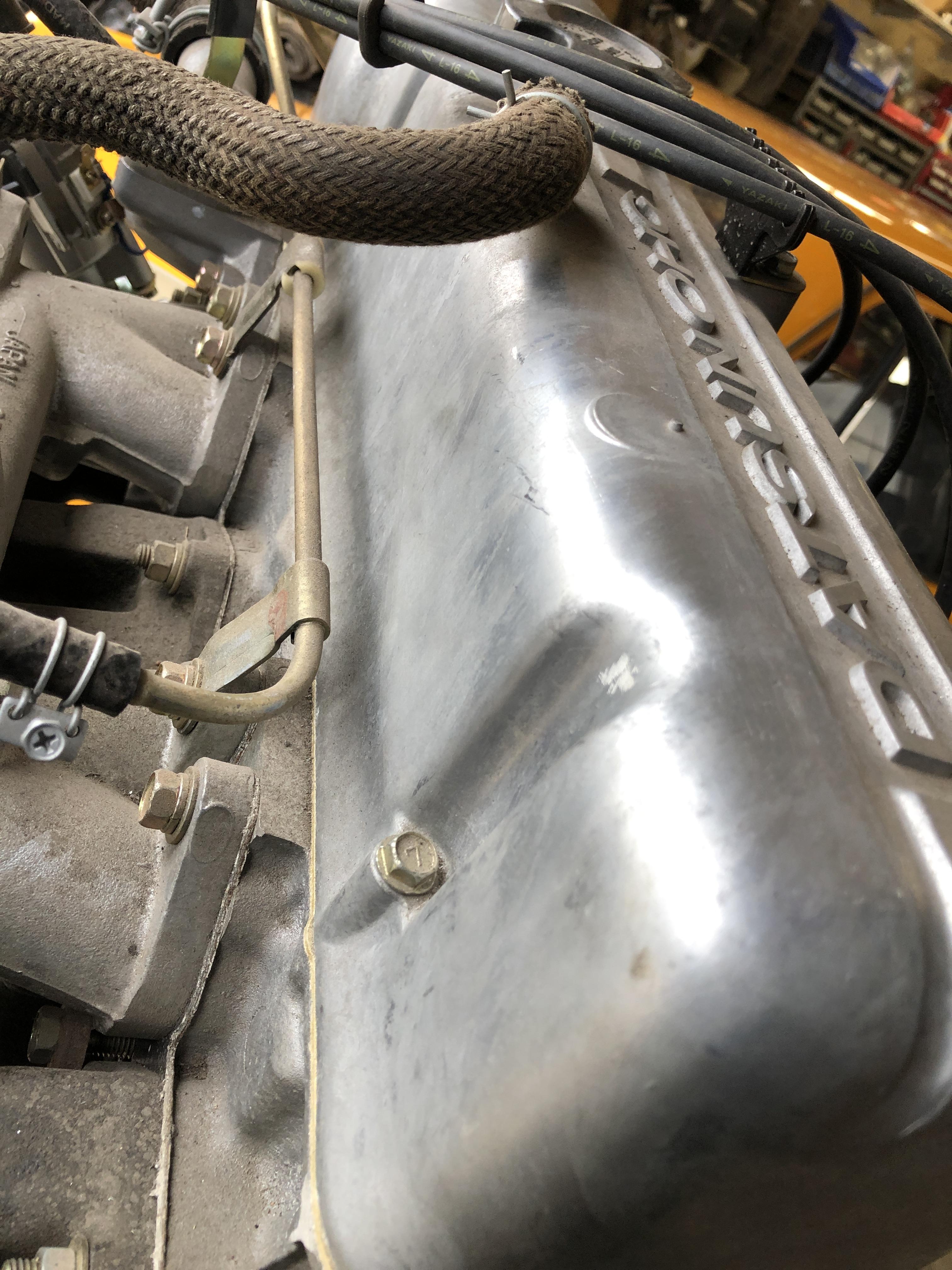
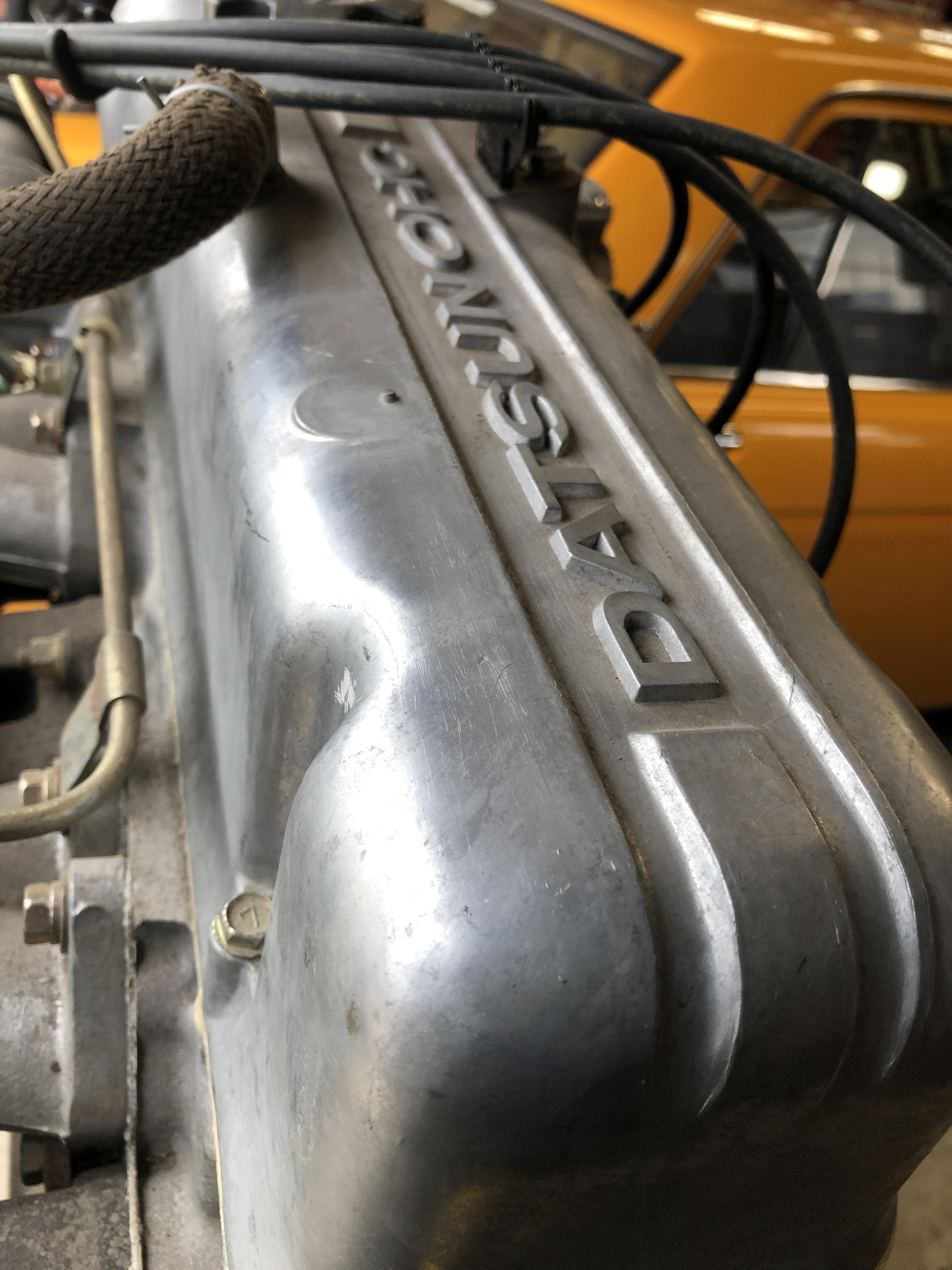
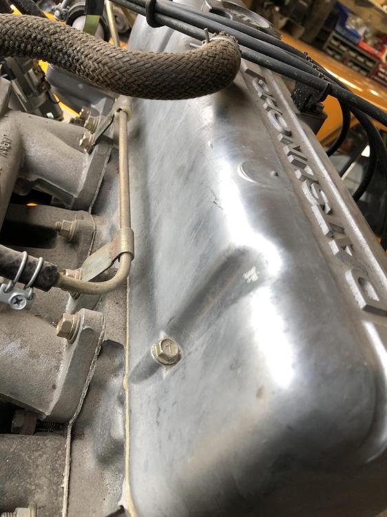
I have an NOS L4 valve cover that looks a lot like the ebay cover. The finish really appears like un-finished raw aluminum, and there is lots of variability in the finish. It is not shiny, but has some reflective qualities. It does look a lot like freshly fine bead blasted, but more variable and smoother if that makes any sense. This cover has been in open air for 40+ years on an NOS L18 SSS motor on display. I'll try to get some sun lit pictures that show the variations. There has I believe been some continued oxidation with time while in my possession.


-
Just a note here, but I recently solved a wheel shake issue by buying spacers that were actually flat, unlike the POS cast pot metal ones I was using that were anything but flat. Zero offset seems to work on most z's. If the ones you like only come in small + offset's then a thin spacer can make up for that. I'm talking +12mm and smaller. Assuming tires = or under 225 in width to fit inside the fenders.
-
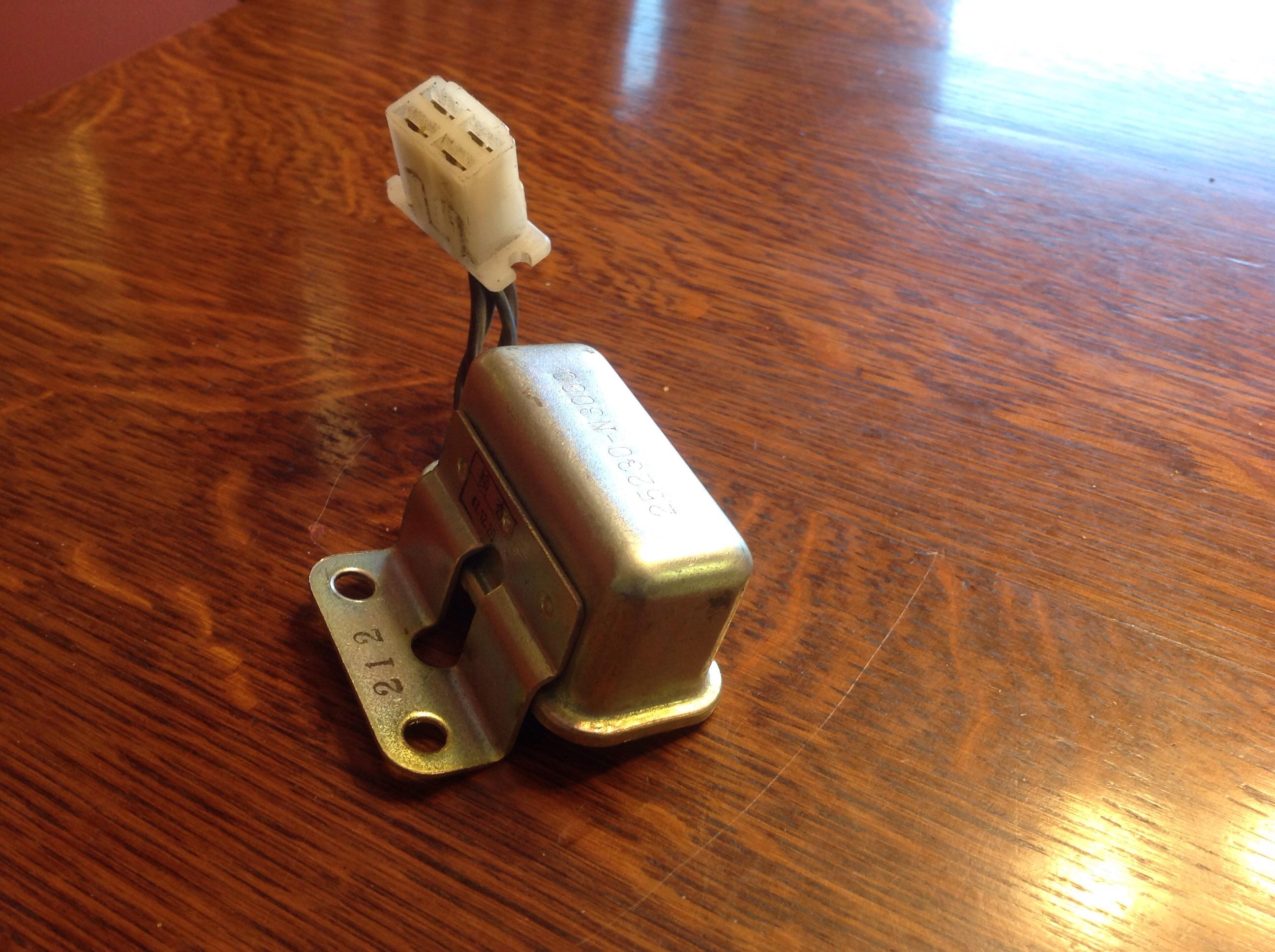
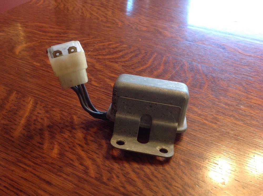
So close. I could put the male plug on it and it would do just fine. I do have the right relay (but its ugly), so I can either exchange housings or just put a plug with new male pins and new shell and even get the right pin in the right position using the correct relay as a guide.

-
BAMMMM. Trigger pulled. I have SO many sets of lovely wheels that don't fit my overkill TTT BIG brake kit on my 510 it's making me mad. No more. Anybody want a set of Big front brakes for 280ZX? (And 510, but nobody here cares.... snifff). Gonna be available in a couple of weeks.
-
I've had several aluminum rims with quite severe and deep rim dents fixed (curb impacts) without them being cracked in the process. They use heat to soften then manage somehow to remove the dent. They can then machine and polish as required to return the rim looking perfect. I'm sure that if you just take a hammer to a dent in an aluminum rim you will likely crack it. I've been SO tempted to just tap a LITTLE and see what happens... Still make me wonder how such high force "instant" impacts make such a nice consistent and BIG dent without cracking it Right then and there. Maybe the aluminum alloys they use are more malleable than we assume.... I'm getting my ball peen.....
-
I have replaced the "blade" style OEM seals with a "Bulb" style weatherstrip like the door seals. The bulb has to be on top of the pinch weld rather than on the side like the door seals. I got mine from McMaster Carr. I can find the part number. 1120A122 for 1/16" edge, 7/16 bulb diameter https://www.mcmaster.com/catalog/125/3615 The OEM style seems to be about the least effective way to make a seal I can imagine. I think I kept a few of the OEM clips that hold the OEM weatherstrip on if you decide to get the reproduction of them.
-
I have a couple of decent tight hinge sets left over. I went through my stash last year and threw away 2/3's of them because of excessive pivot point slop. There is just about no way to keep you hood aligned with sloppy hinges. PM me and we'll get some on the way.
-
Found it! http://www.tsimportedautomotive.com/gearreductionstarters.html
-
Great find indeed. I have a memory about a billet starter that was available a few years ago. Will have to dig through hybridz and see what I can find. THOSE were 100% american made IIRC and would be bullet proof without the Asian quality risks. Only down side is the appearance would not be stock, and the cost would be more, but what price are you prepared to pay for a lifetime starter?
-
Mr H, I will do all i can to ensure you have a Zed for the trip. There may be an available ZED closer to you than you realize. PM me or z240@shaw.ca
-
See that pin with the C clip on it? Remove and replace with a 1/4 bolt with washers on both sides, and a self locking nut. Feel free to use a M6 bolt if you want to keep it all metric. Tighten the nut until it squeezes the fork closed just enough to take out the slop but still lets the linkage move. Did this in first in 1975. Still a thing.
-
I've used Damper Doctor to rebuilt a couple of HB's, very happy with the result.
-
The head bolts, like ALL M10 female threaded holes in the block, are 1.50 mm pitch. Pretty much all other M10 bolts on the car are 1.25mm pitch, certainly all the suspension related bolts.
-
Man has lathe, mill and drill press and most definitely 'could' have made my own, did considered filing, but was not at home at the time of the discovery and need for a solution. Had to resort to the solution of spending money. But thanks for the vote of confidence.
-
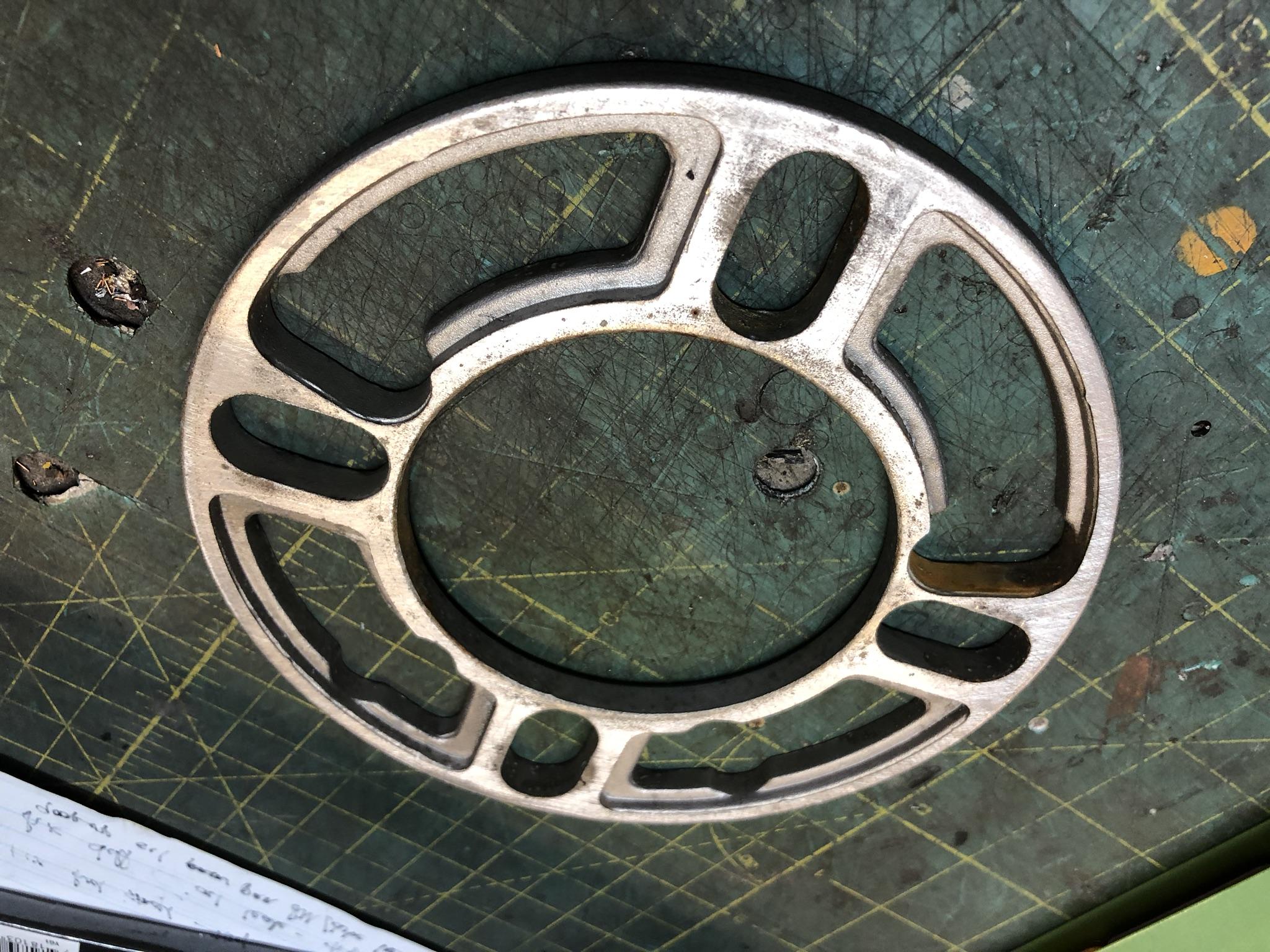
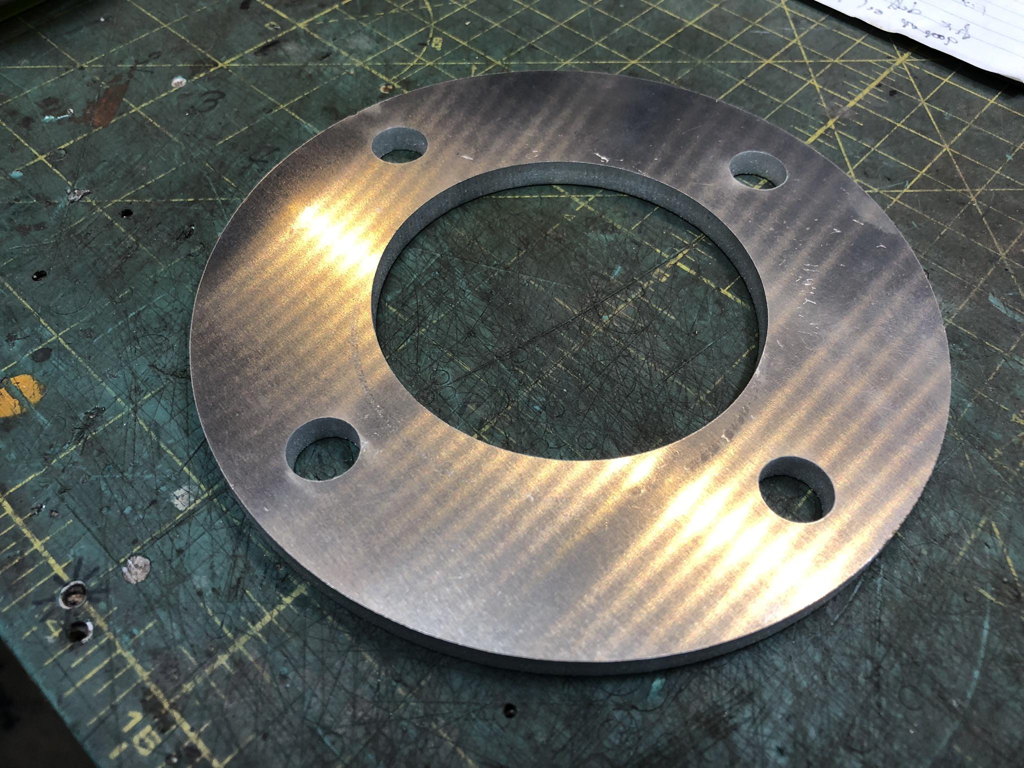
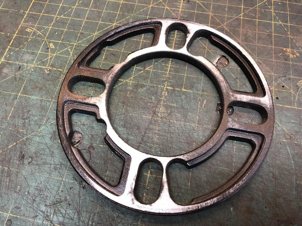
I just never seem to learn. Needed some 1/4 to 1/2" spacers for the last couple of sets of front wheels I've had on my 510 to get them to clear the coil overs and fit the car right. Everybody does this to trim-out-the-fitment thing. Well I went to the speed shop and bought some that are 3/8". How hard is it to get a flat piece of metal with some holes in it? Well I learned the hard way, again. Very hard apparently. The only ones they had were, shall we say, not very expensive. These cast aluminum or unknown pot metal something's are absolutely pieces of you-know-what. I have been battling wheel shimmy for months, and never dreamed it would be these things. They are only 0.015 inch variance in thickness, but that amount, magnified out to the wheel/tire diameter made the wheels run out by 0.050 inches, which is nearly 1/16". Replaced them with these. Had a local metal shop laser cut these in 15 min. 5.75 diameter, 3" center hole, 1/2 diameter bolt holes at 4.5 bolt spacing. 1/4" 6061 TOTALLY REMOVED ANY AND ALL STEERING WHEEL VIBRATION I HAD, and it was not insignificant. Almost made it unpleasant to drive. Reminded me of this Beware! I wonder where they are made.... hmmmmmm.... Another way to see just how anti-flat these are. I sprayed them lightly with black and gave them a quick surface sanding on my reference flat abrasive platten (3/4" MDF with glued on sand paper).


-
Hate to say it, but I send you a couple of B spacers if you want....
-
The key to your search is summed up in four letters: BSPT and I suppose some numbers and symbols..... 1/8, 1/4 3/8 and maybe 1/2
-
IMG_2433.mp4
-
Here is the last dyno pull. IMG_2432.mp4