zKars
Supporting Member
-
Joined
-
Last visited
Everything posted by zKars
-
left side tie rod is the one with left hand threads. Right side is right hand thread. That assumes no one has replaced the left side with a right side inner rod (common since left sides are hard to find), which would make them both right hand thread. Look at the threads and how they lead into the lock nuts.
-
Removing that. Wedge bolt is a trick indeed. Best way is to drill a 21/64” (will explain in a minute) in the case to the left of the pin (in the picture) so that you insert a punch and drive it out. Use heat on the pin area to help break it free. You also have to support the outer end of the rod so when you hit the bolt with the punch, it doesn’t just flex the rod. Chunk of wood between rod and case will do it. Then tap that hole for 1/8NPT and plug it. Guess what size hole is needed for 1/8NPT tapping...
-
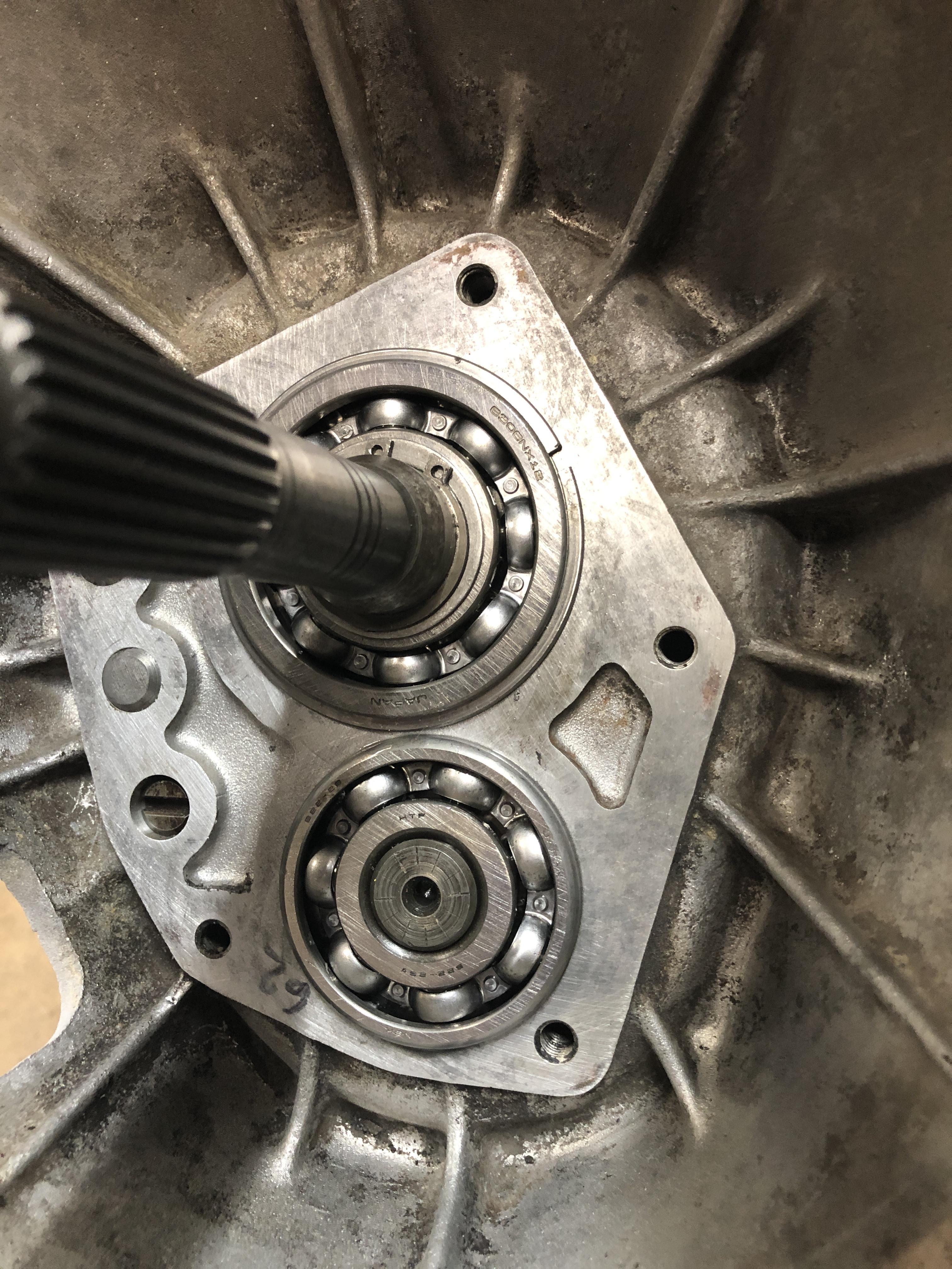
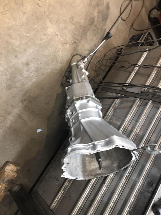
Did the final assembly this morning, went pretty smooth. Have to work on my technique to get the tail housing on and the shift forks aligned at the same time. Good trick here is to take the reverse lock out assembly out and look in there with a flashlight. It’s in line with the shift forks and the tip of the shifter rod, so you don’t have to guess much. The other part of this is to make sure you have the through/retaining pin that is just ahead of the shifter in place, and the detent/spring thingy with the 19mm hex cap by the shifter in place as well. This keeps the shifter “kept” within the correct confines of its movement while you get the shift fork finger in “just” the right spot. My fancy 62mm front counter bearing “schnicked” perfectly into the front cover. The C type front cover went over it without issue, needed 4mm of shim. I can happily select all 6 gears. There are no extra parts laying around. AND I tried the reverse switch function with my slimmed down shift rod. It works! Only comes on in reverse. Bought it a new switch as well. I stripped the cases and repainted with 2k epoxy primer (Eastwood stuff in a can) then VHT aluminum color caliper paint.

-
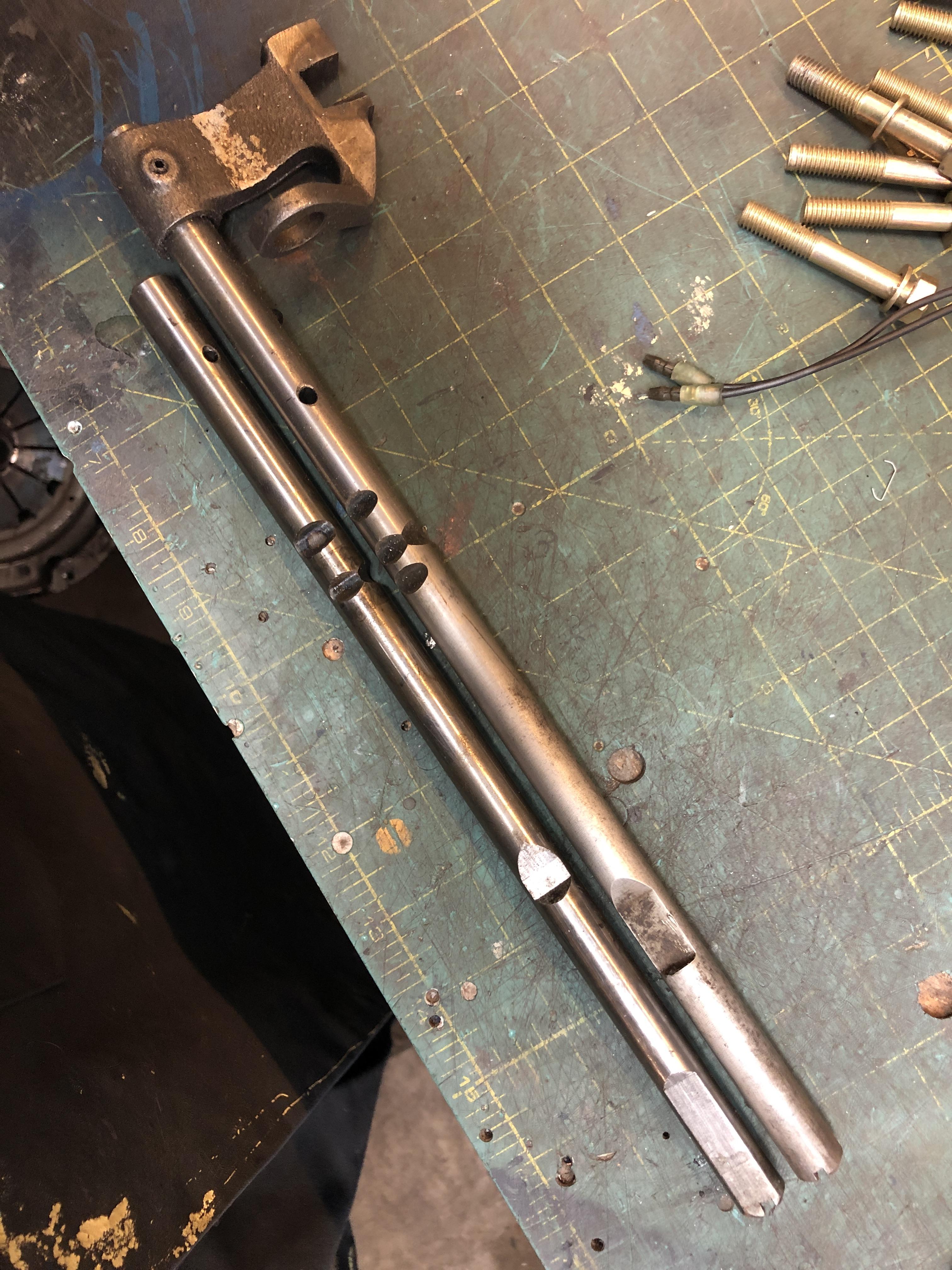
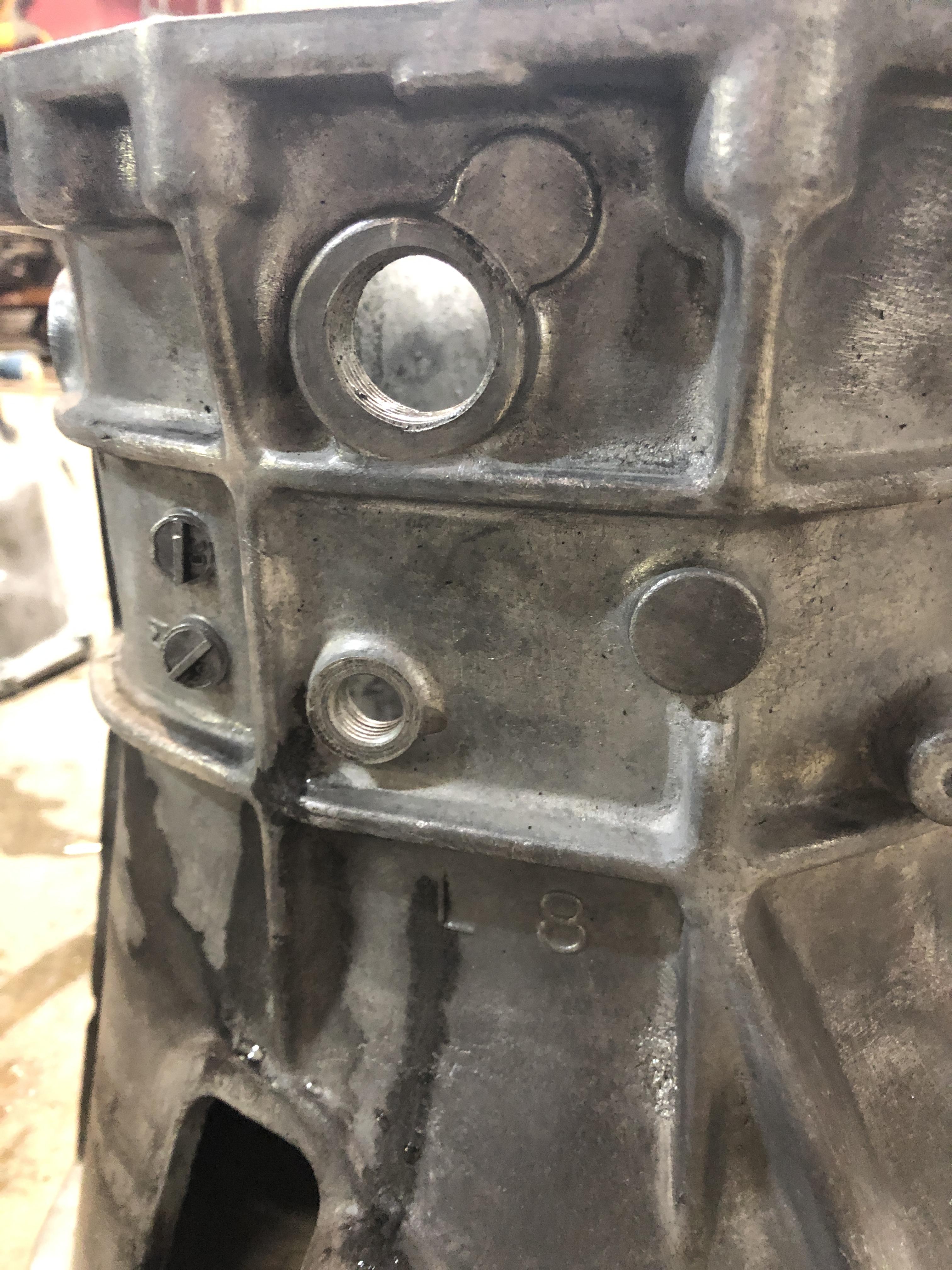
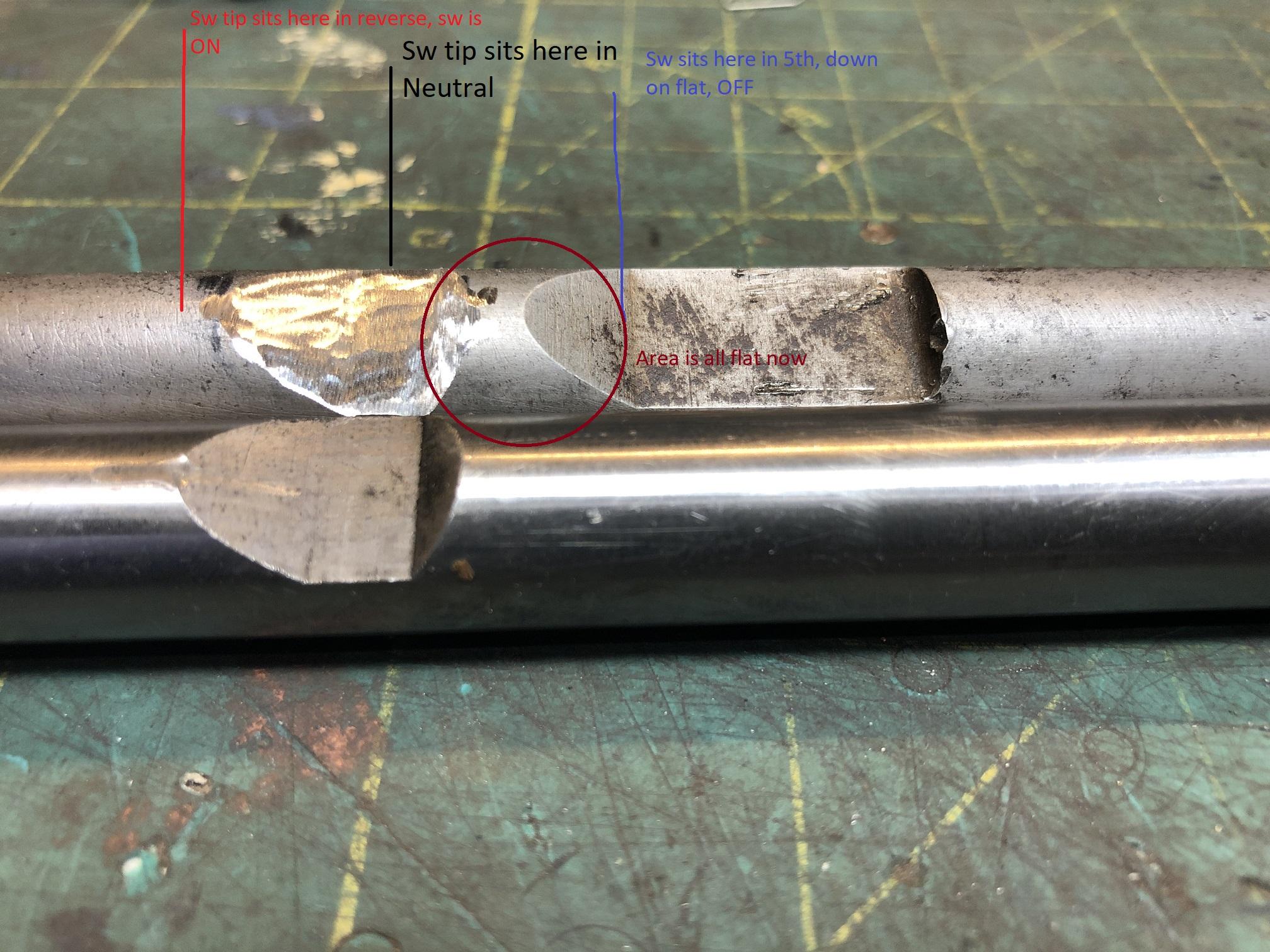
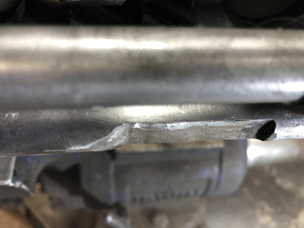
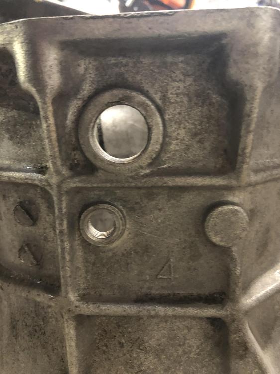
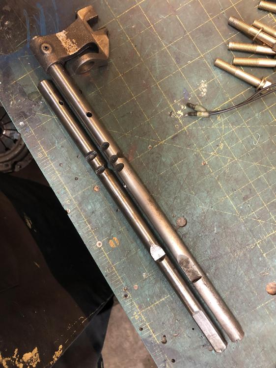
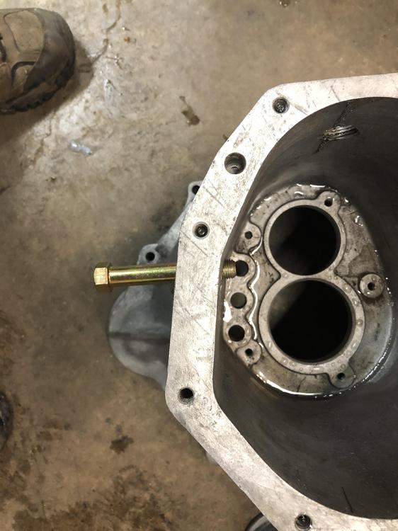
Last bit of ingenuity is in regards to using a 4 speed bell housing, and the issues it raises. Back a few pages, I spent a lot of time creating a way to may a 56mm hole into a 62 mm hole. I did my first test on a somewhat expendable 4 speed bell housing. It went better than expected, and I decided to put a 62mm front counter shaft bearing on this gear set to hopefully improve life span. So I of course feel compelled to use my new bell housing with the 62mm hole. The worst thing about the 4 speed bell housing, is that the reverse switch hole is in the wrong place. It's about an inch too far back. Location on a 4 speed \ Location on the 5 speed, further rearward The proposed solution is to make a new hole in the bell housing in the right spot, and plug the wrong spot. Not a terrible thing to do, it's a M14x1.5 threaded hole, I have a tap. When I looked closely at it, I noticed the hole does not pass through the case at 90 deg to casting. I threaded an M14 bolt in the hole to show you the angle. This doesn't look fun to drill or tap. I'm afraid if I go through at the wrong angle the tip of the switch won't hit the shift rod properly. So..... So I looked at the two shift rods. 5sp on the right/top. 4 sp on the left/lower. The depression where the tip sits when in neutral or 5th is of course farther forward on the 5sp rod (down in the pic is toward the front of the trans). Why not just extend the depressed area on the 5 sp rod farther back (up in the pic, sorry) so it ends at the same place as the 4sp rod and lets me leave the switch where it is? So that's what I did! I first created an identical pocket in the 5sp rod in the same spot as the four speed rod. Then realized that would/might keep the light on in 5th too, so I flatted the area between the old and new pockets. Just imagine that the full diameter bit in the middle is gone, and its flat all the way across between the two flats you see here. Now the switch will turn "on" when the tip rides up the slope from the flat spot to the rod full diameter, as the rod moves to the right (forward) going into reverse. Will stay down when going to the left to get 5th


-
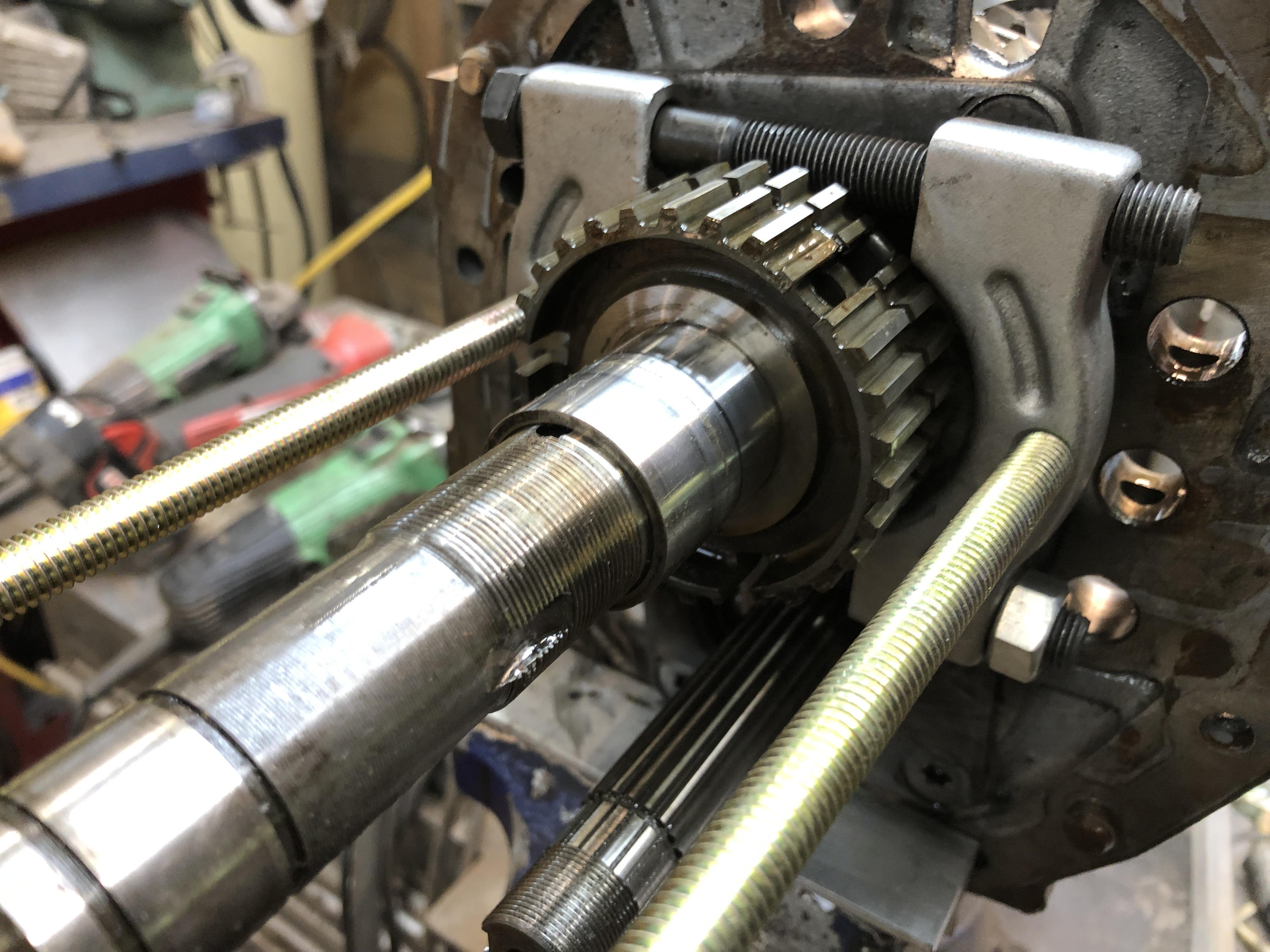
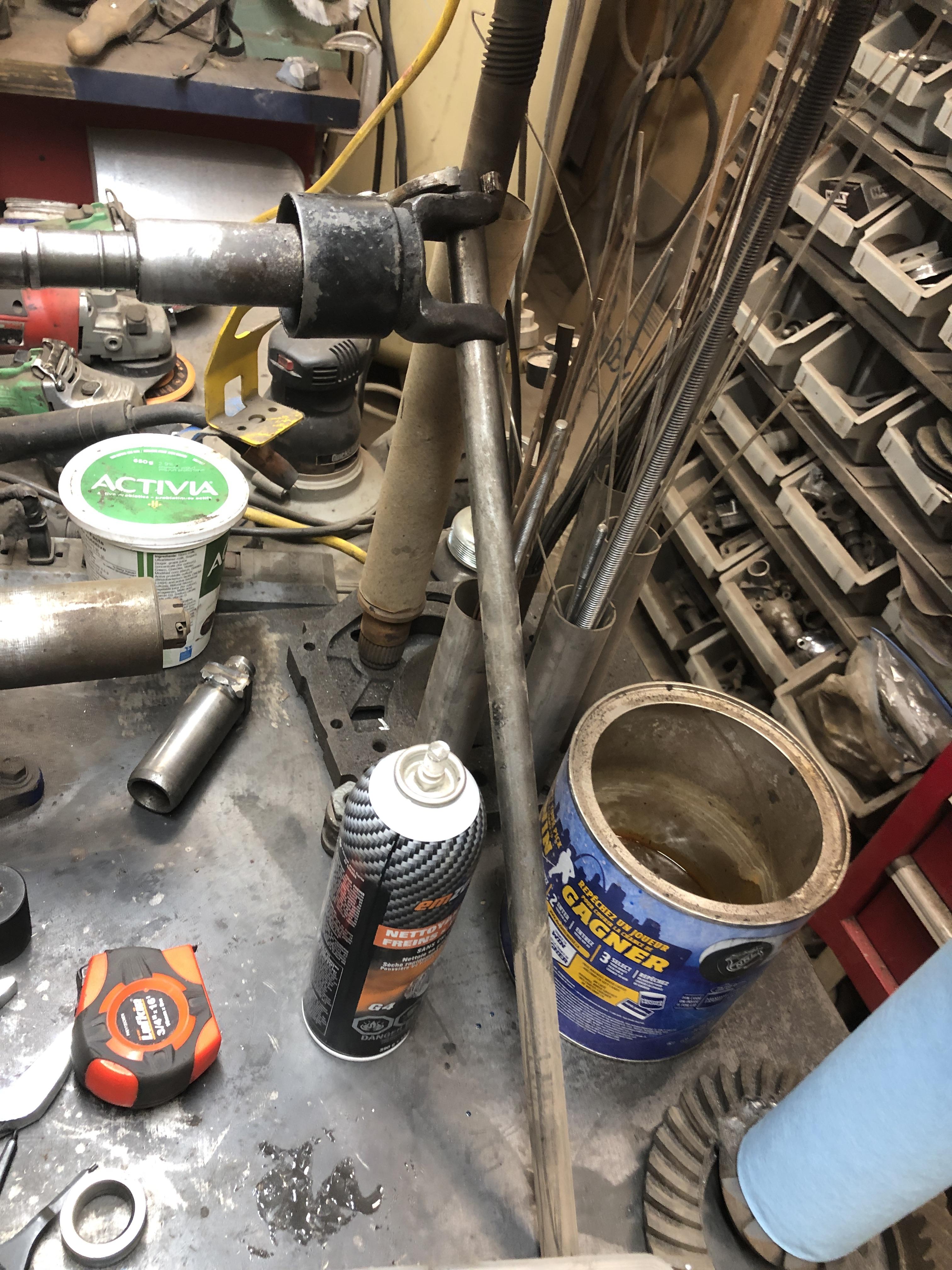
There is always at least one really grumpy part of every job, like spindle pins, and for this job, its a very tight bearing sleeve that lives under the 5th gear cluster. It is pretty easy to pull off, you use a bearing splitter in front of the 5th gear syncro hub , and a set of 18" rods to draw it all forward until the sleeve is over the threads, then its free. Back on is more grumpy. It sits just ahead of the threads on the main shaft for that big nut, so if you can get it far enough on to start the nut, then just tighten the nut down to drive the sleeve to the end. Well, not quite, the threads run out just before you get to the end. You can use the thick washer that goes on at this spot (the one with the ball or little dowel that sits in a groove to prevent it spinning) to add a bit of thickness to finish driving it all the way with the nut back on. I build a pipe with a hole in the end just the right diameter to hit the end of the sleeve. It slips over shaft that sits against the sleeve and lets me beat it in place with a mallet. You will need something like this if you can't get it on far enough to see threads that then allow you to use the nut to finish the job. This is not the pipe tool thing I built, but it is the world's deepest 38mm 1/2" drive socket. Probably about 18" long. I built to let me do and undo the big nut easily. Bought a 1-1/2 socket, cut it so just the hex was left, then welded it a 1-1/4 black iron pipe (standard hardware store gas or water line) and then welded the back half of a 1/2 drive socket to the other end.


-
Well shocking but true, I actually assembled ONE whole transmission over the last couple of days with new bearings and syncro's. It is also the one I chose to do the hybrid mix of close ratio 5 speed gears (4th gear pair) with all the other 720 truck transmission gears to give me a .65 OD, while retaining ratio's for most of the other gears that still quite reasonable. See the posts a couple of pages back with the spread sheet. Anyway, the 4 gear main and Counter shaft gears and associated bits went right on with a hitch into the other wise truck destined parts. I was able to put the main and counter gear pair sets in and get the shafts pressed, well actually pulled, into the intermediate plate bears using the threaded nuts that are one both shafts, with a tube of just the right length. 3.375" long (1.25 ID tubing) works just fine for both. I had all the gears on both shafts, didn't do the front set separately like the FSM suggests, way too much work. Just takes a tiny bit of juggling of both shafts with one hand has you get the two shafts started in the bearings with a soft tap of a rubber mallet. Then tighten the two nuts (the big 1-1/2" one and the 27 mm smaller counter shaft) one, then the other to draw the shafts in sequentially until seated. Since the two shaft gear sets are mated yet, you can't throw both 1/2 and 3/4 into gear to lock the shaft, so you have to use an old drive shaft yoke and some pipe or whatever to lock the main shaft. There are plenty of "Special tools" in my arsenal now, and having old driveshafts to harvest bits from is critical. As is various lengths of pipe in handy diameters. I'll make a post later that shows all my "SFT's" as I call them (special field tools) and what I used them for.


-
Never had to replace them, just clean and repack as mentioned. Maybe in extreme cases if the balls are badly pitted. Rockauto shows many aftermarket replacement options; https://www.rockauto.com/en/catalog/nissan,1972,240z,2.4l+l6,1209169,suspension,strut+bearing,7460
-
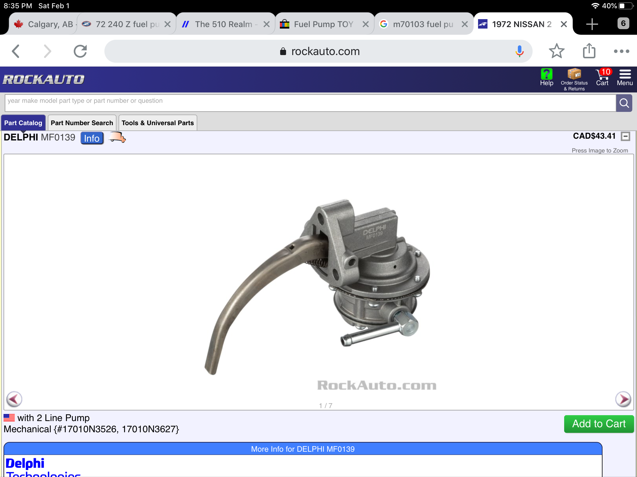
Checking RockAuto for 72 240Z, there are a couple of pumps that look like stock ones, a GMB and a Delphi. I wonder if their diaphragms and valves are interchangable with the old stuff. For $43 CAD, might be worth a try. I should cull through my old pumps, disassemble and get all the old diaphragms and valves out and see what looks usable still.

-
I also remember a post about using a certain Toyota pump that is still available through parts dealers, like RockAuto. Identical internals, just steal the diaphragm and valves and plunl them into yours. I ordered and used one once when that thread came up. At least 5 years ago I think. I wonder how far back my RockAuto order history goes....
-
I have a few old 240 senders, I could send you one and you could use it's float. I'd splice the metal rod close to the float, don't try to "remove" the float per sey. I'll see if the 240/280 floats are the same size.
-
I see Amazon.com has something you might like Manual Steering Rack & Pinion For Nissan Datsun 260Z 280Z S30 1974 1975 1976 1977 - BuyAutoParts 80-70087AN New https://www.amazon.com/dp/B01M3XT0M3/ref=cm_sw_r_cp_tai_SIGlEbGKJAGJ2
-
Ok, early are about 1” wide, late about 1.25”. Very different. You don’t want to put a narrow bushing on a wide flange rack, the rack with slide around. There are threads on here about folks have lots of fun getting the poly rack bushing to seat properly. Do some searching to see the solutions. You can shim a narrow bushing to fit on a wide rack, but I dare you try fitting a wide bushing into a narrow flange rack.
-
Other than some apparent ratio differences in the early rack, all racks are interchangeable 240/260/280 to the end of 280z. There is only one uniqueness, and that is the size (width) of the bushing flanges and bushing, the left one near the steering shaft . Early racks are narrower, later (260 onward approx?) are wider. You just need the correct width bushing. The energy suspension poly bushing kits for the 240 and 280 are only different in the left rack bushing width. 7.10101 (240) and 7.10102 (260-280). I wish I could remember the flange width on the two models, let me go measure some.
-
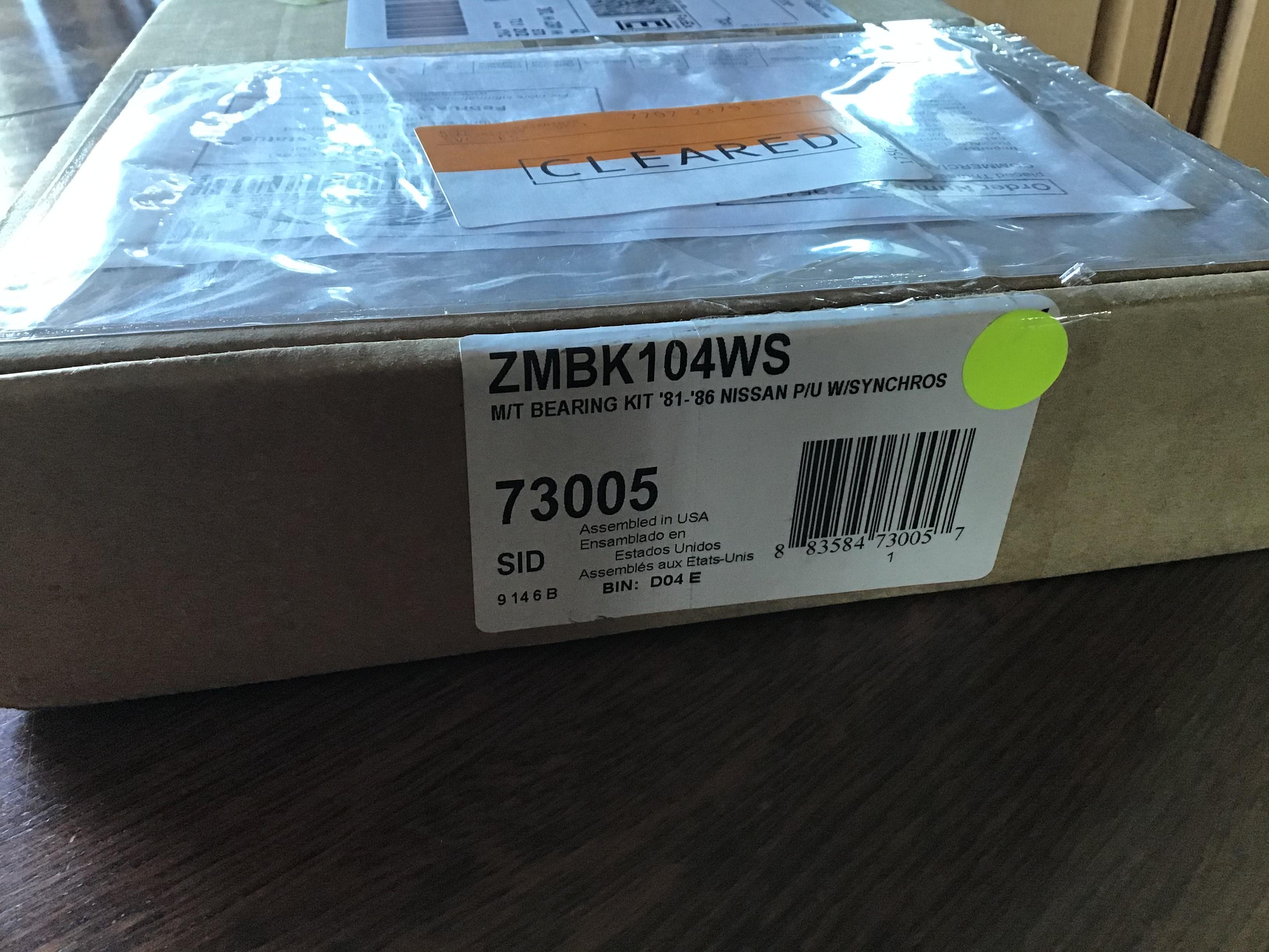
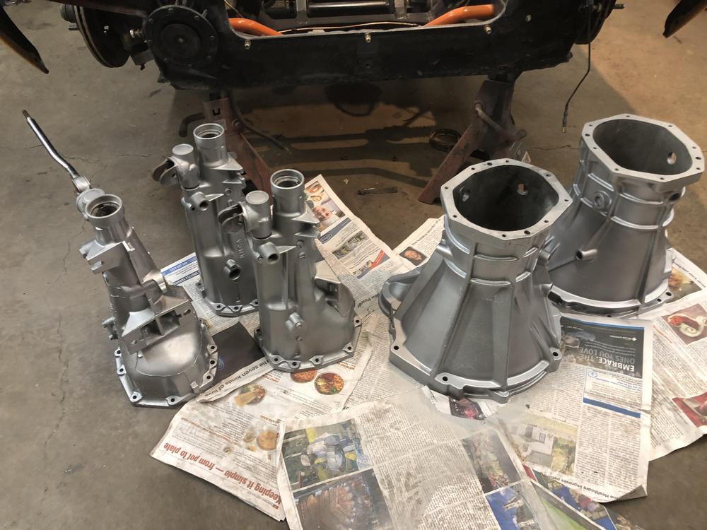
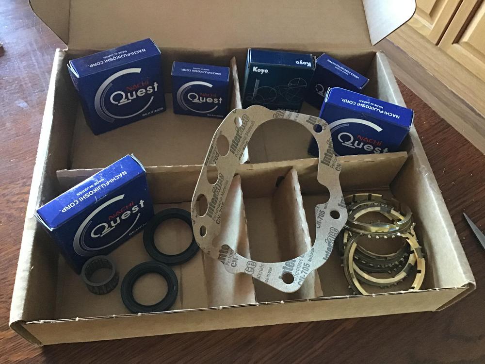
The Doctor is now in. Finally. Today’s news is about rebuild kit pricing. I have actually found a cheaper source for the Bk104WS kit. Rockauto! I found the kit when looking for 200sx parts (don’t ask, it’s what’s been keeping me ‘occupied lately) ZMBK104WS is the part number. Was looking under 1980 200sx. $87.37 CAD ($66.76 USD) and about $25 CAD shipping. Expecting to be buying cheaper quality parts, I waited until they arrived. Well they are here. Everything in the box appears to be identical to the other kits from drivetrain.com and transpartsdistributors.com. Okay, one bearing is a Koyo rather than a Nachi. Everything else appears identical. Got here faster than the other kits too. One week vs two. Now if I can just store away of a few thousand 510 parts that just showed up, MAYBE I can actually rebuild one of these dang transmissions! Arggghhhhhh!!!!

-
Hatch alignment can be a pain in the glass... sorry. I would suggest removing the main weather stripping and getting the hatch to fit without it. Not an easy decision, but it will remove the main impediment to adjusting things and being able to tell if your adjustment is doing what you think. The hinges do have a L and and R stamped in them somewhere. Do make sure you have them on the right side, though I’m not sure why them being wrong would cause one side to be higher than the other. You never know.
-
Ron, PM me. I have that other thing in an envelope waiting to get to you, I can add a housing and cover. Yes, all two bolt covers are the same across the years. There must be eleventy five variations of the lower housing though....
-
Once it thaws a bit here I’ll go sift through the dizzy spares and see what antiquities I can resurrect....
-
I have a bunch of those. Send me a PM and we’ll exchange info.
-
Stock length Z31 turbo axles do not fit the s30 chassis, as you are finding out. The shorter of the two can ‘just’ fit the long side if you’re lucky. This has been an on-going discussion for years. Someone made a set of shorter axles shafts discussed on hybridz.org. Jon Mortensen I think? Long since un-available. Driveshaft shop has a solution I think.
-
I think the short nose R200 started with the Z32 in 1990. The much sought after CLSD’s with the finned covers from the 87-89 300zx turbo’s were long nose.
-
You are correct.This is for my Haltech 750.
-
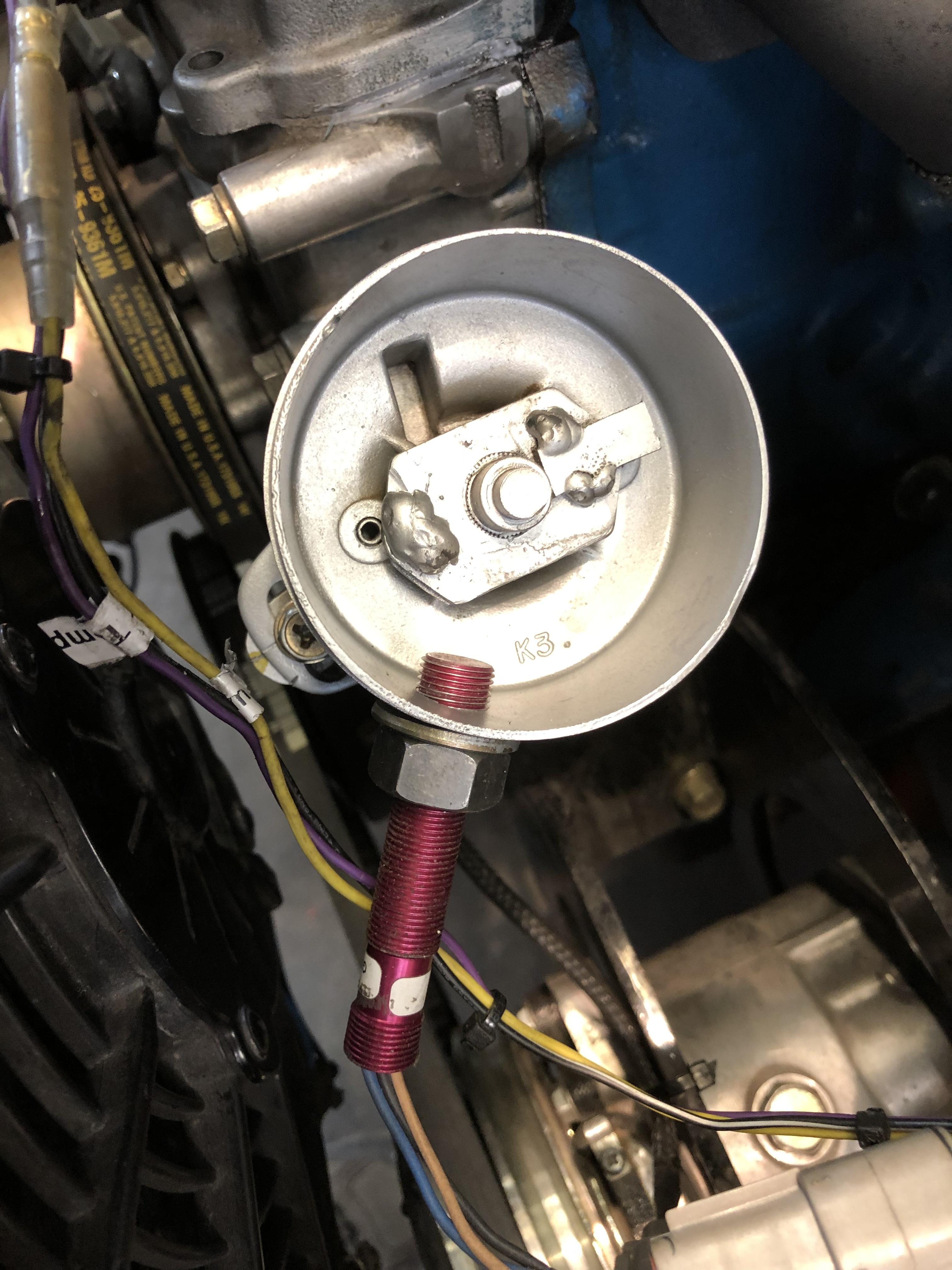
So simple. That “Was” a points dizzy I think. Any, including an L4 dizzy can be used. Once you take it apart, the plate at the bottom had the two pivots for the advance weights. cut the shaft just above, remove the pivot posts, weld on a little square chunk of metal, a weld blob on the other side for a bit of counter balance (very scientific). Machine the case down to just above the cutoff point. Drill a hole for M12 x 1 thread on the sensor at the same height as the new welded on tab. Come up with a lid. I machined a lip to make a 2.75 OD in the case. You can just leave the stock dizzy cap if you want and not shorten the housing at all. If you start with an L4 dizzy, you can get some great looks when folks count 4 towers, let alone that there are no wires. Best thing is, timing doesn’t matter! Only one wrong place for the sensor line up, ie the exact same spot as when the crank trigger is at the missing tooth. ECU can’t handle that. I have a few spare dizzy’s. I can make you one.
-
You can get pretty basic triggering with an old dizzy, a spot of welding, and a hall sensor. DIY baby! You don’t even need to thread the hole for the sensor straight! (Yikes!) Yes, there is a trigger wheel on the crank as well.

-
Sorry no tricks with the bearing, but I have a trick to putting that C clip back on. You put your back into it, literally. Get one of those 1” wide tie down ratchet strap things, sit in the car, put the steering wheel retaining nut back on the tip of the column. Wrap your tie down strap around the threads behind the nut, sit a bit forward, then wrap the strap around your back under the arms more or less, and tie it off back to the column. Then get the snap ring tool ready, (you did put the snap ring on the shaft before the nut and the strap right?) just lean back and pull the column toward you. Put the snap ring back on, then lean forward to remove the tension. You’ll be surprised how easy it is. After you realize you can’t undo the knots you made, wait for your wife to discover you in the garage and set you free. Prepare an appropriate story of how you got that way, while you wait, then invite her to tie herself to the glove box so you can do something together for once.
-
No gib locks. Something I do miss. I put duct tape over the gap where the scales and the indicator on the adjuster wheels meet to prevent rotation of the handles if I run into one. Hardly ideal. I can come up something better.