Leaderboard
-
Captain Obvious
Free Member5Points10,081Posts -
conedodger
Free Member4Points12,513Posts -
xs10shl
Free Member3Points339Posts -
CW240Z72
Free Member3Points229Posts


Popular Content
Showing content with the highest reputation on 03/23/2023 in Posts
-
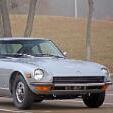
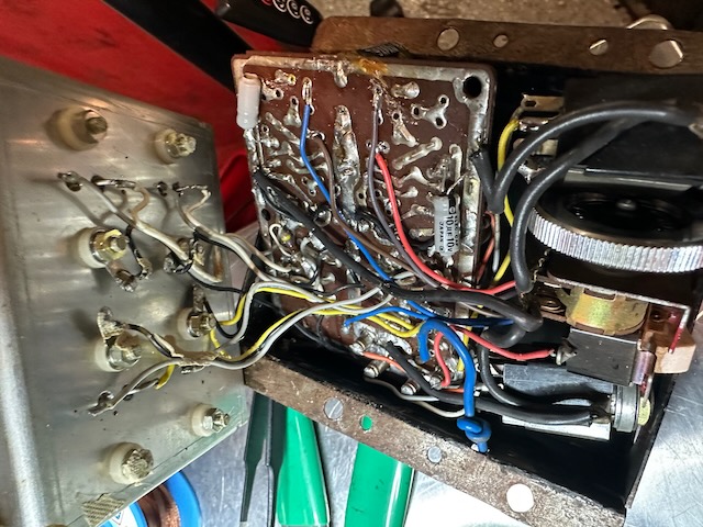
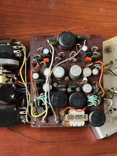
That board is mostly symmetric about the middle. Undoubtedly the two independent channels. It'll save you quite a bit of time with the reverse engineering because you only have to do half. This is what I mean: I would guess that the few components at the bottom of the pic that are not symmetric (the coil and the big cap) are most likely input power filtering, and the big cap at the top is most likely a power supply filter as well. The big ring of solder trace around the board perimeter is ground and the big strip running down the middle is most likely the high side of the supply.
 4 points
 -
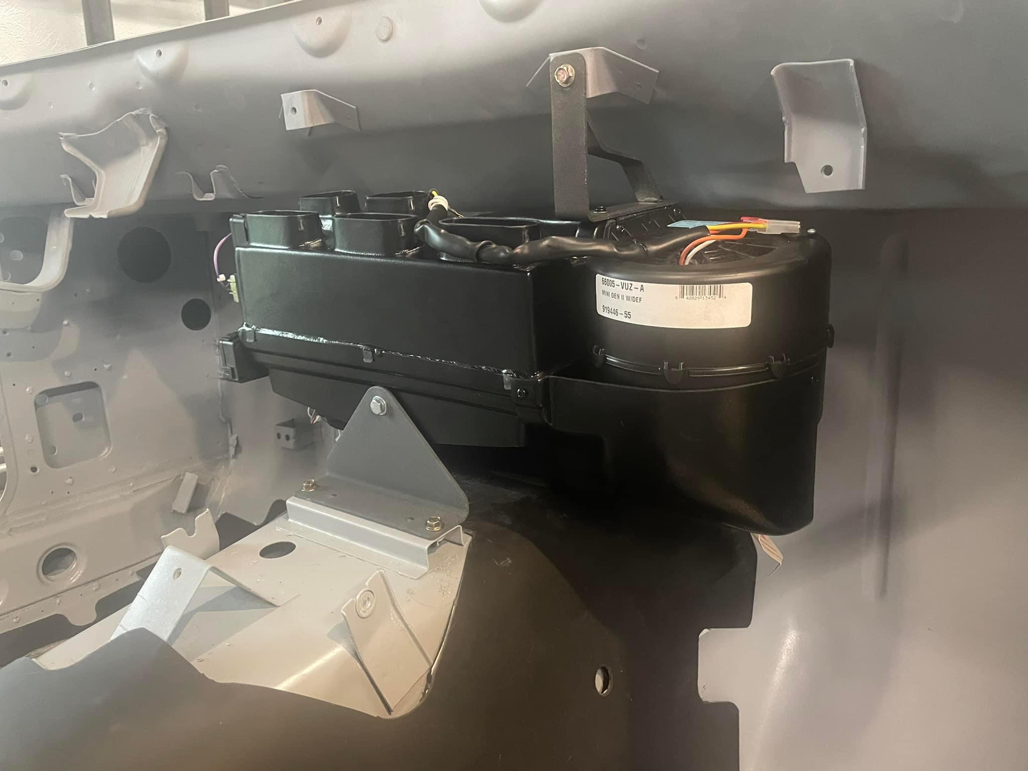
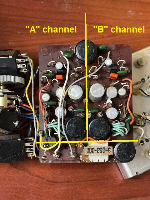
3 pointsInstalled the Vintage Air Gen II Mini and made some progress on the wiring. For anyone who’s installed these, the harness that comes with the unit is long and bulky. Ended up pulling most of it off and tailoring it better for the Z.
 3 points
 -
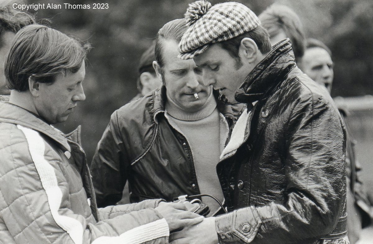
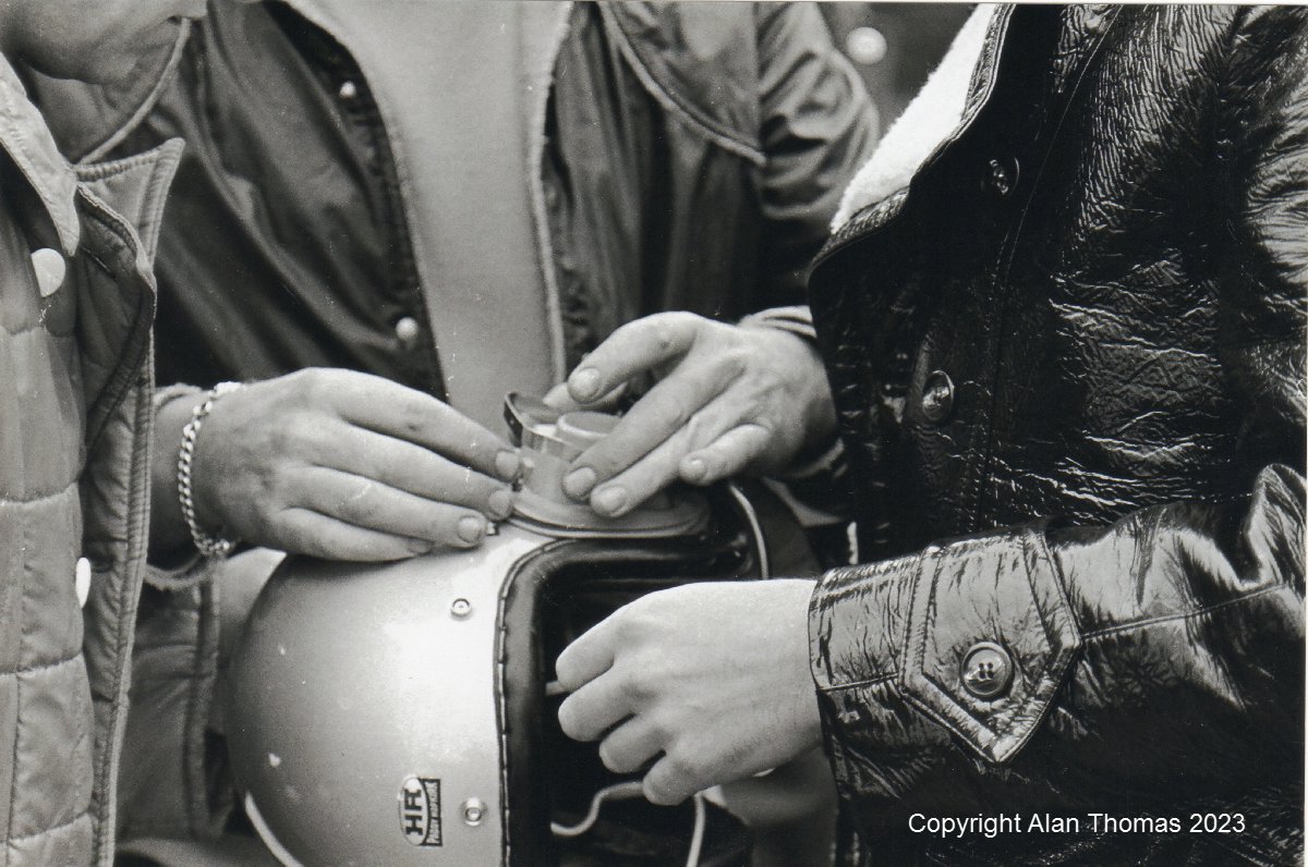
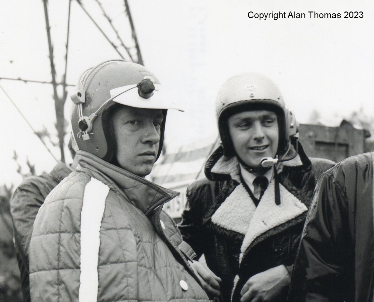
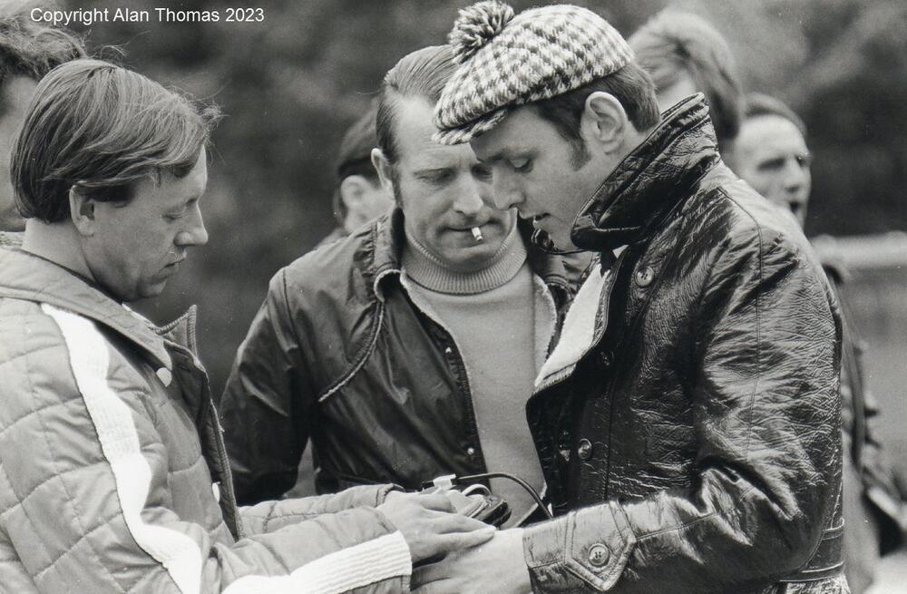
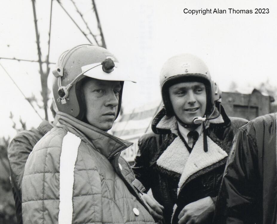
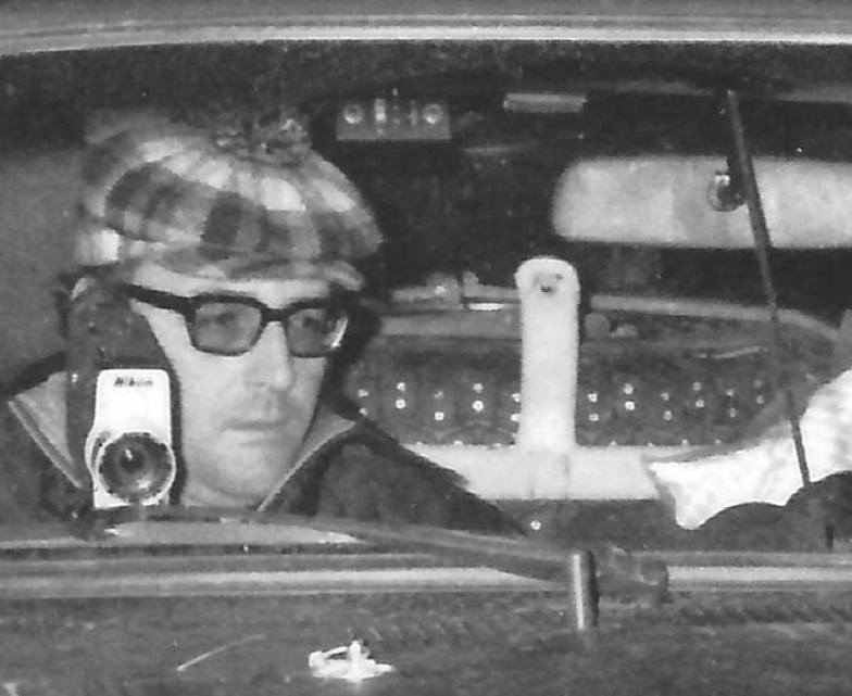
Nissan's Works team called this system an 'Interphone' (the period English vernacular being 'Intercom') and they had already been using similar systems on previous Works rally cars. They were especially important/useful on the East African Safari Rally with its long and arduous road sections between special stages, where it was still necessary for the navigator to call the route to the driver, often at fairly high speeds (high noise). They would have been necessary on 'recce'/reconnaisance practice and ice note runs where the crew needed good communication to make accurate pace notes on events such as the Monte and RAC rallies. For the 1970 RAC Rally, the crews were using single-ear interphones that could be used also be used over specially-adapted Paddy Hopkirk crash helmets. Kind of unwieldy, and it is easy to see why the next step was to integrate the earphone on the inside of the helmet. Some photos of testing in the UK prior to the 1970 RAC Rally, where the crews were getting used to the new systems: Rauno Aaltonen, Hans Schuller and Tony Fall: Detail: Aaltonen and Fall: Tony Fall with Works team mechanics, team manager Takashi 'Waka' Wakabayashi on the left:

 2 points
 -
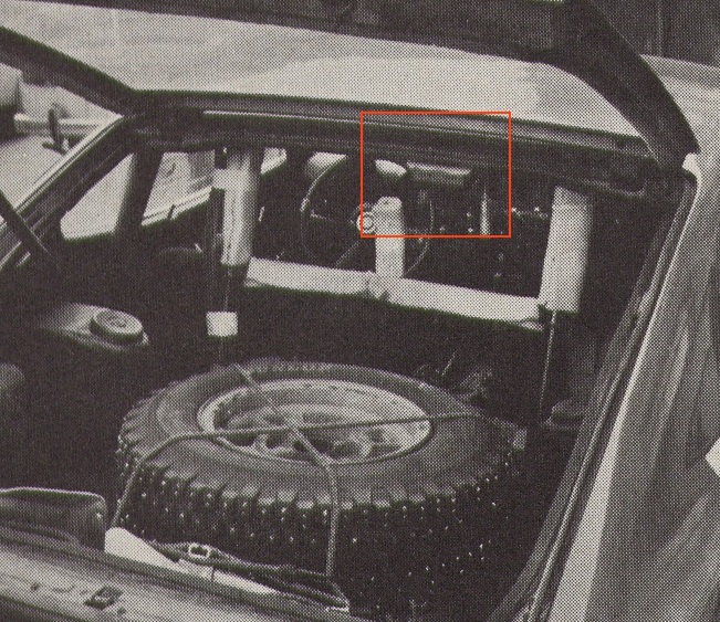
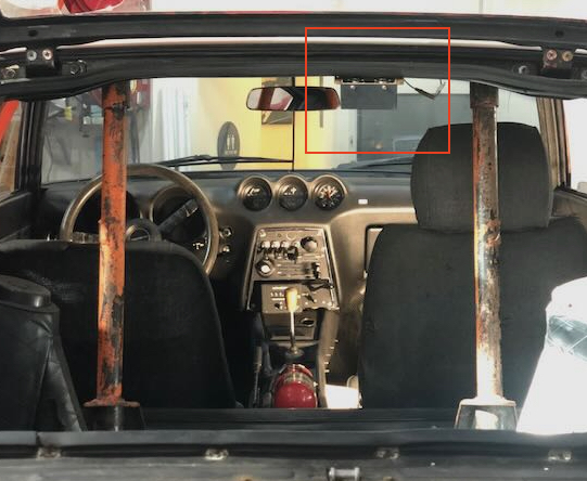
For the 1971 Monte Carlo, the Works team appeared to employ (from what information I can gather) what is basically a 2-channel power amp with gain control to facilitate communication between driver and navigator. The essentially muffler-less cars were already loud to begin with (by all accounts), and subtracting any sound deadening, plus the incessant constant rattling of two in-cabin fuel pumps, one could imagine the occupants would be losing their voices around day 2. Interestingly, I have a fair number of period photos where the team did not appear to be wearing headsets while underway, so perhaps the system didn't provide the expected benefit, apart from when the occupants donned helmets. I believe mine to be original hardware, as I have a detailed picture of it installed in the car from the 71 Monte Carlo (last picture below), and another from October 1971. It is a very compact 12V device, made by Teikoku Dempa Co. LTD, using 1/4" headphone jacks to a pair of mono headsets with microphones. Teikoku Dempa has been in business since the 1940s, making radios under the Clarion brand name. It's not clear to me whether this device was stock, a special order by the Works team, or potentially even a modified over-the-counter item. The unit wasn't working, so I decided to take it apart for a little exploration and diagnosis. It didn't take long to discover a fair number of leaky capacitors, which are in need of replacement. Probably best to replace all that I can find components for. Although Ive taken a circuits class in my youth, I'm not an electronics repairman, so I'm on the hunt for an enterprising repair shop, likely a tinkerer with an oscilloscope who would want to spend a few hours reverse engineering the board, replacing the caps, and matching the system to my headsets. I'm taking a first-pass stab at creating a circuit diagram using some simple circuit design tools, so whomever takes on the job isn't starting from scratch. Worst case scenario is that I'm forced to put the original electronics aside for storage, and retrofit the box with a modern 2-channel amp, so it at least looks the same. In the mean time, it would be fun to find out where the Clarion on/off switch and volume knob came from. Perhaps there is an old Clarion transistor radio which uses the same equipment?

 2 points
 -
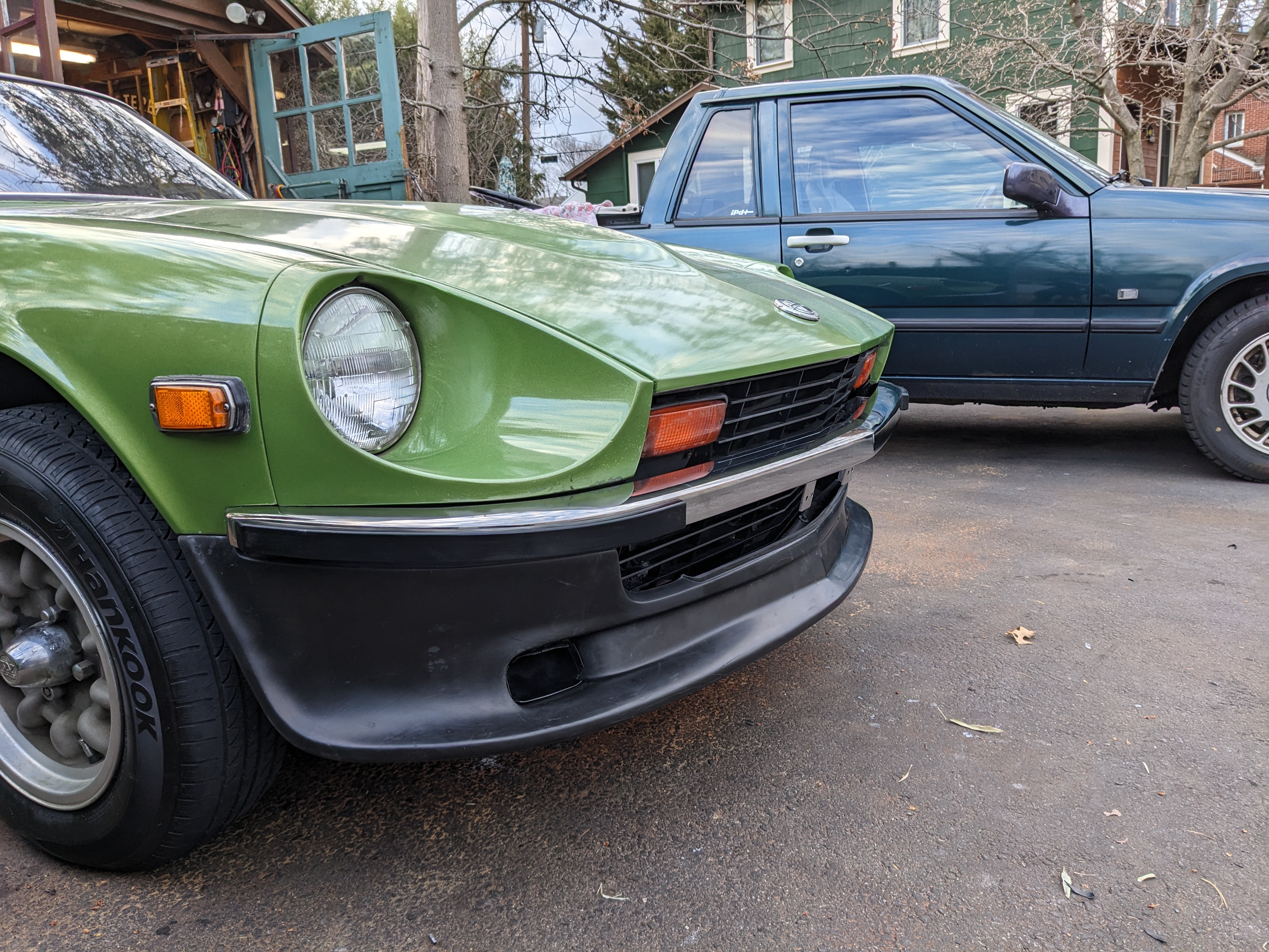
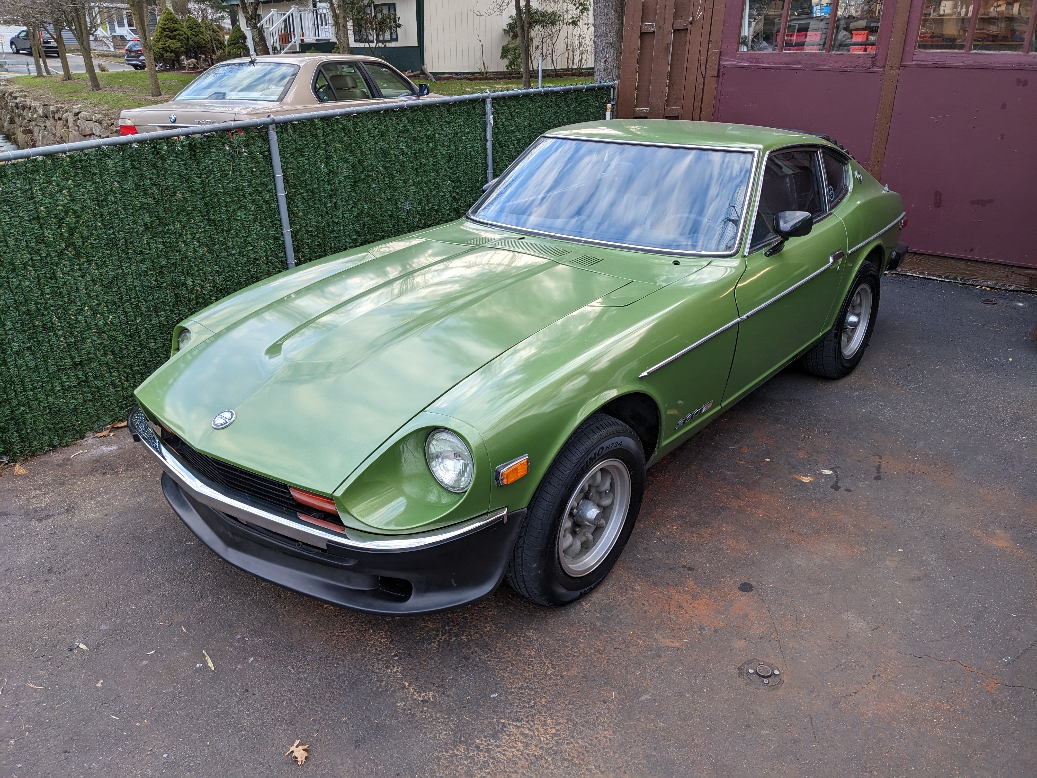
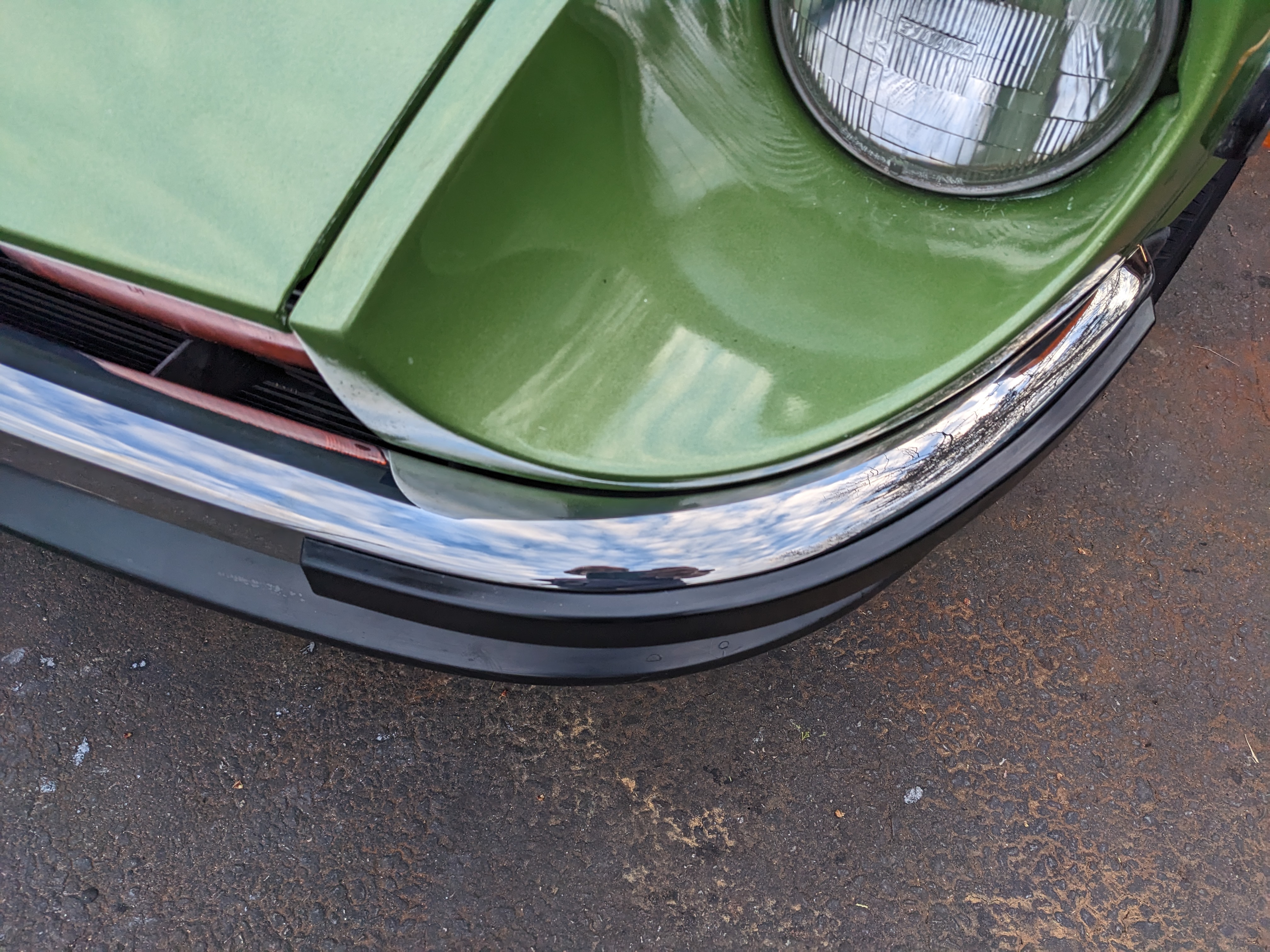
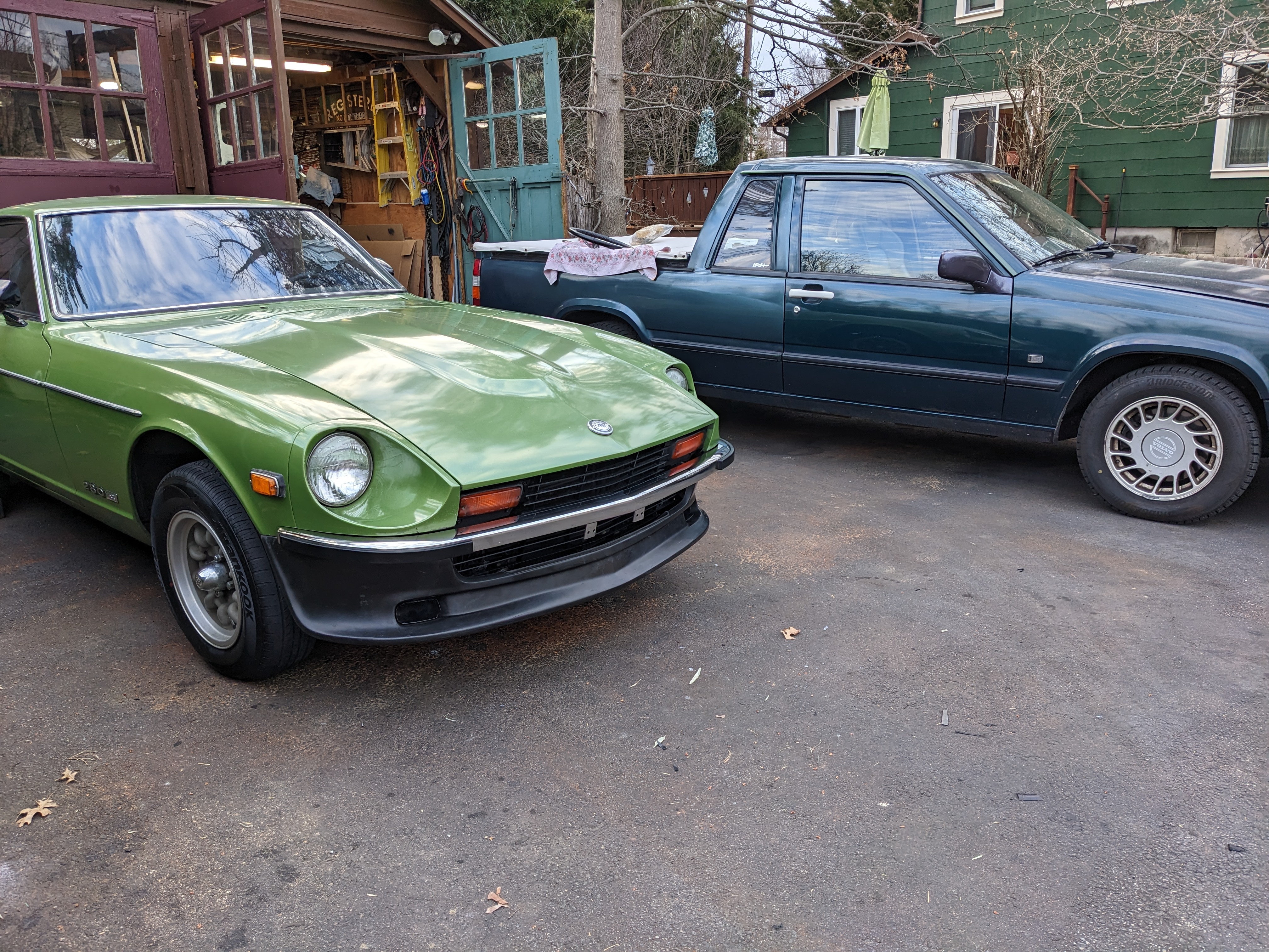
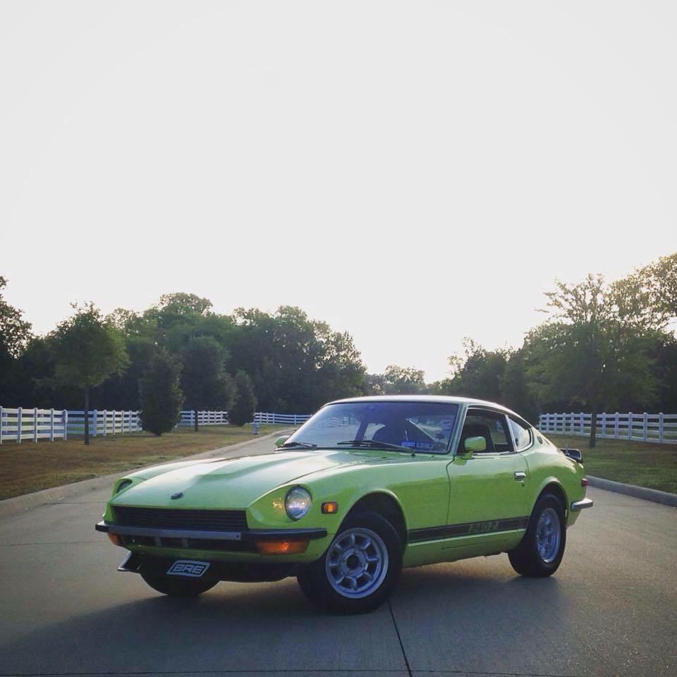
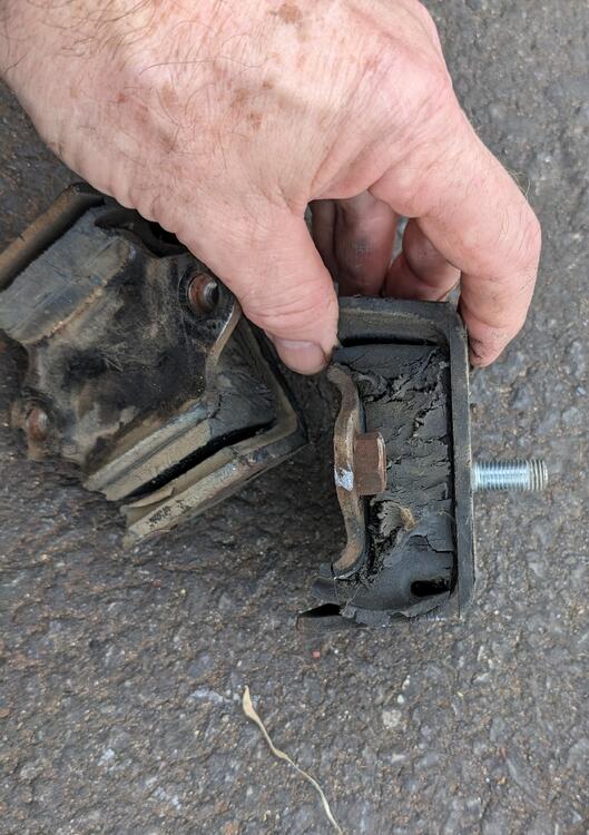
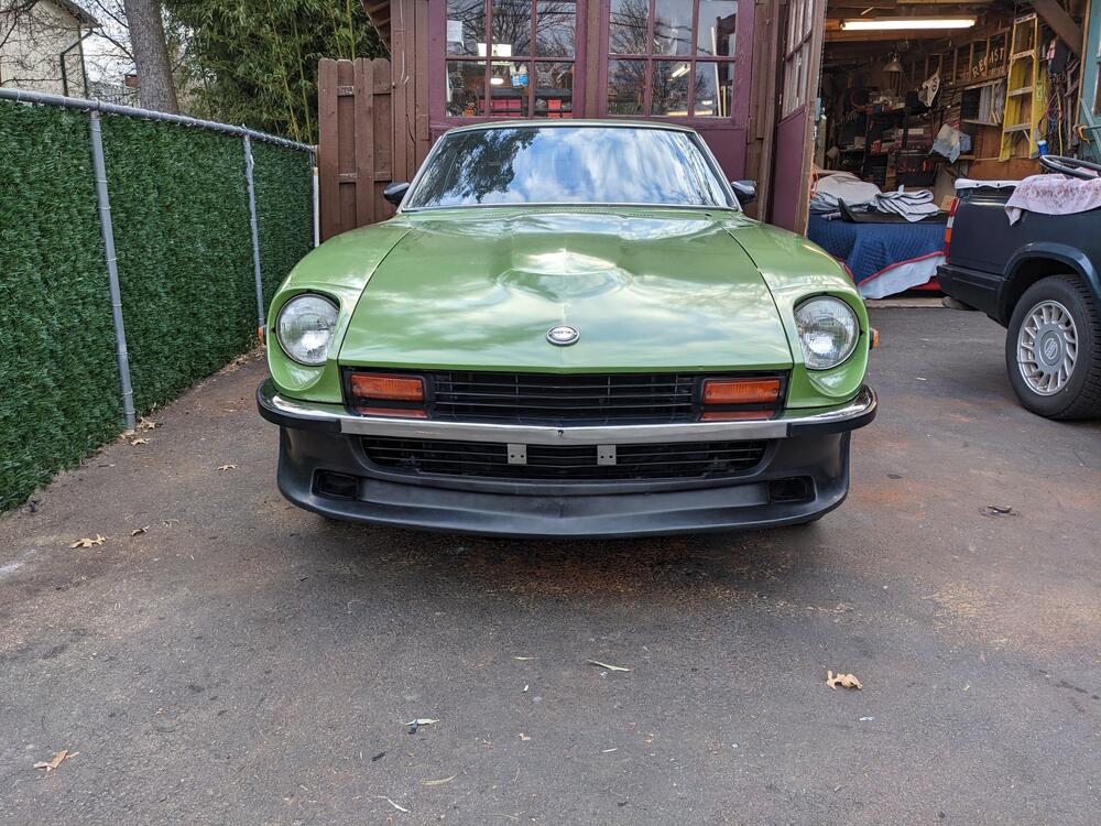
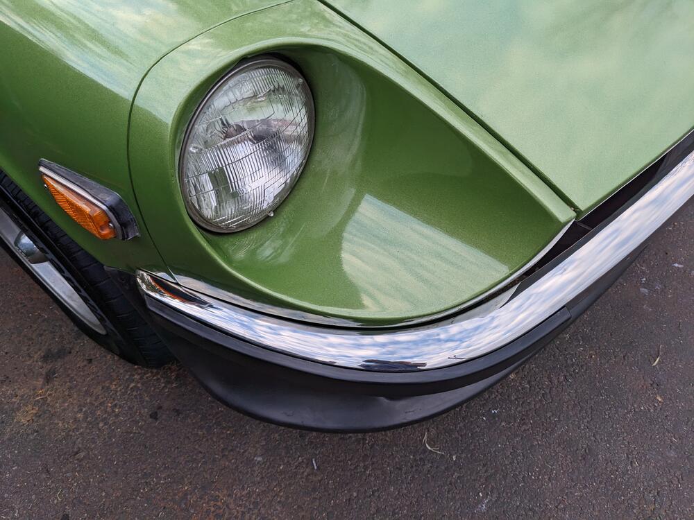
Finished the install after work - did the motor mounts first, since I had the car jacked up anyway. The car has 250K miles, I don't think he did any suspension bushings or any mounts in all that time. I'm happy with the fit & look. Not sure I needed to splurge for the Skillard grille, but I didn't want any of the gap I've seen without a full grille The bumper fit is very good


 2 points
 -
2 pointsSo the car has an aftermarket stereo, correct? Given that, and that these cars didn't come with much in the way of hi fidelity audio systems back then, the OEM wiring shouldn't be relied upon to get the audio signals to the speakers. And the speakers. Rockford Fosgate speakers are typically good, better quality speakers. Rather than rely on the less than adequate OEM wiring, you should have dedicated, proper gauge wires running from the stereo to the speakers. Also pay close attention to polarity, and keep the phasing the same right to left. This is more of a sound quality thing than a longevity issue, but still important. Impedance is also important, the speakers need to match the impedance of the stereo output. If the stereo has 8 ohm output, then the speakers should be rated for 8 ohms, if it has 4 ohm output, the speakers should be 4 ohm.2 points
-
1 point
-
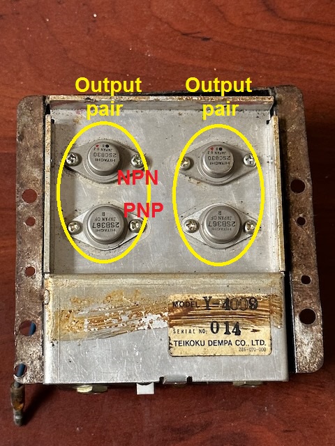
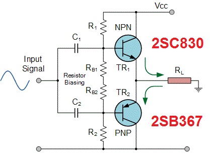
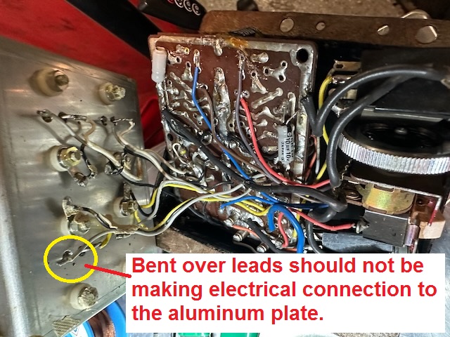
A little more info to help out... You shouldn't have to spend a lot of time figuring out how the four big output transistors are connected. I can tell you that they are "push-pull" amplifiers consisting of a pair of NPN and PNP transistor pairs. In other words, each channel has a pair of complementary transistors, one NPN and one PNP. Like this: With credit to the source - https://www.electronics-tutorials.ws/amplifier/amp_6.html. Schematically, they are connected basically like this. Note that the surrounding components like the resistors and caps are most likely a little different, but the basic scheme looks like this: One other thing to note is that the four big output transistors should be electrically isolated from the aluminum plate to which they are mounted. They are bolted to the aluminum plate as a heat sink, but the connections should be mechanical only, not electrical. With that in mind, things like bent over leads making contact to the plate would certainly prevent the unit from working, and could cause permanent damage. Can't tell from the photos if there is actually contact, but if there is, there should not be. For example:
 1 point
 -
1 pointSince you're going down that path... Most non-industrial facilities in the US are bringing in 208VAC (two phases off a WYE transformer). At the entry point for the facility (service entrance), there is a neutral (return path) bonded to ground. That is put in the circuit with one of the legs of the 208VAC to provide 120VAC. In Canada, instead of using 480VAC as low voltage, they use 600VAC. The fun part is to source parts in North America for equipment to ship to a 50Hz country since almost everybody in North America publishes specifications for 60Hz. The most fun was a project where all of the equipment downstream operated at 60Hz. The generators operated at 60Hz, and it was being installed in Europe. They had to place equipment in between the utility and our equipment to go from 50 to 60Hz. Ships have to deal with this, too. For instance, the US Navy ships are designed to support voltage and frequency used in America. When they get shore power while docked in foreign ports, they have to have the frequency converters between the shore and ship. Going back to @chaseincats (to pretend that this rambling is still a little on topic), as @Racer X explicitly said, match impedance between the stereo and speakers. Mismatched impedance will work, but not as well.1 point
-
Thanks @HS30-H for the period photos - I especially love the driver's expressions that were captured, even if perhaps only by happenstance. Fall looks almost amused at the state-of-the-art rally equipment, as if he feels as if he's been promoted to "flying-ace aviator". Aaltonen, in contrast, has a "Yeah... nah.." look of mild skepticism with the whole exercise.1 point
-
1 pointI used a square 9 volt battery to get the pluses and minuses right when I cared about loud. Now I use my phone and a bluetooth speaker when, hardly never!, I go long. The exhaust is Rod Stewart sounding. I've always thought 12 volt car stuff was the lower 4 ohms because of the lower power 12 volt systems have. 110/120 house volts is 8 ohms. Is it 110-220 or 120-240 AC volts? I've heard both over my life but would like to know.1 point
-
1 pointDear Zed Head, only to let you know that my Datsun is already running well. The problems I was having were due to an immobilizer linked to the ignition relay that was installed by the previous owner. I cut a wire that was energizing the ignition coil. Now problem solved.1 point
-
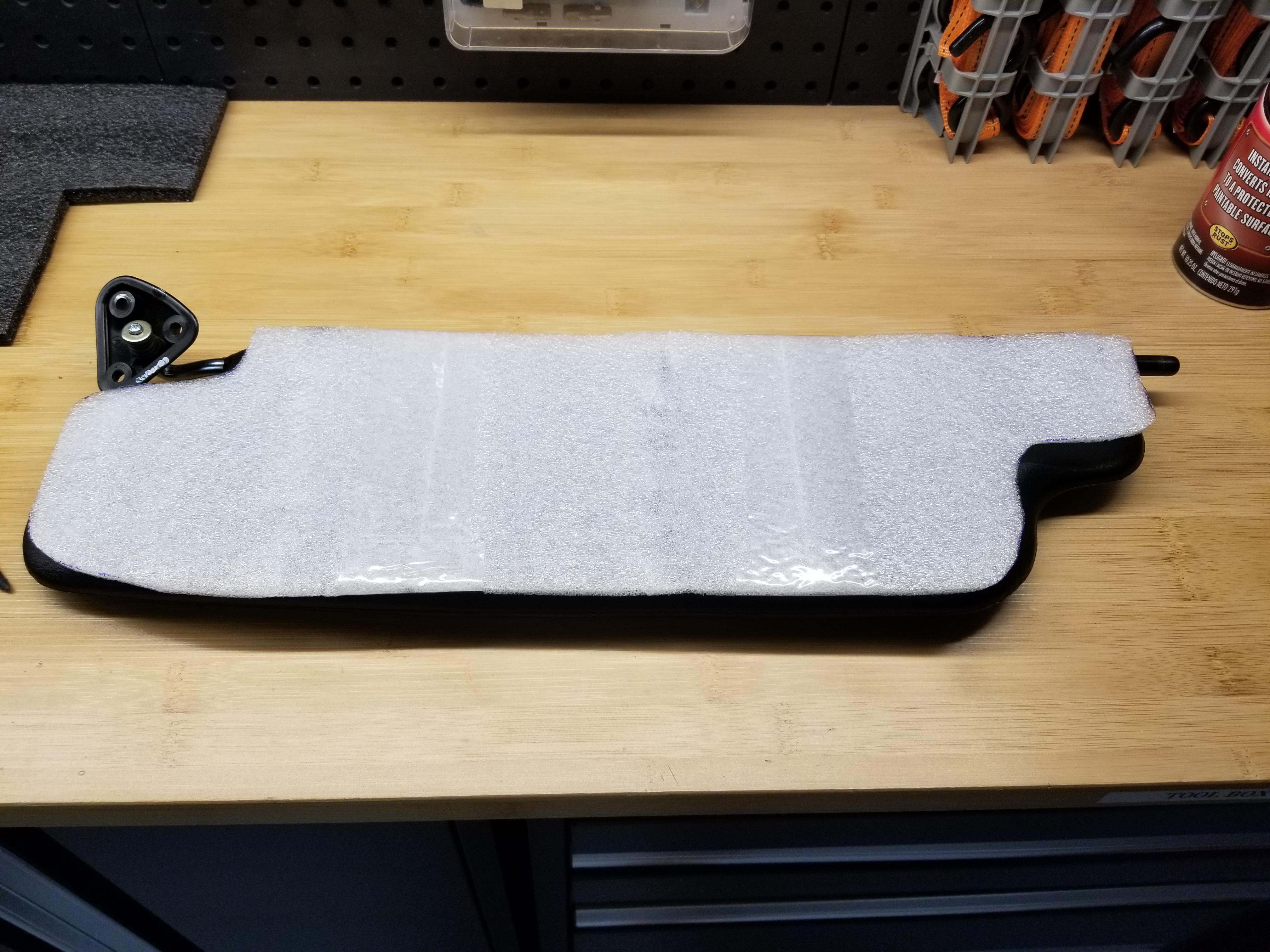
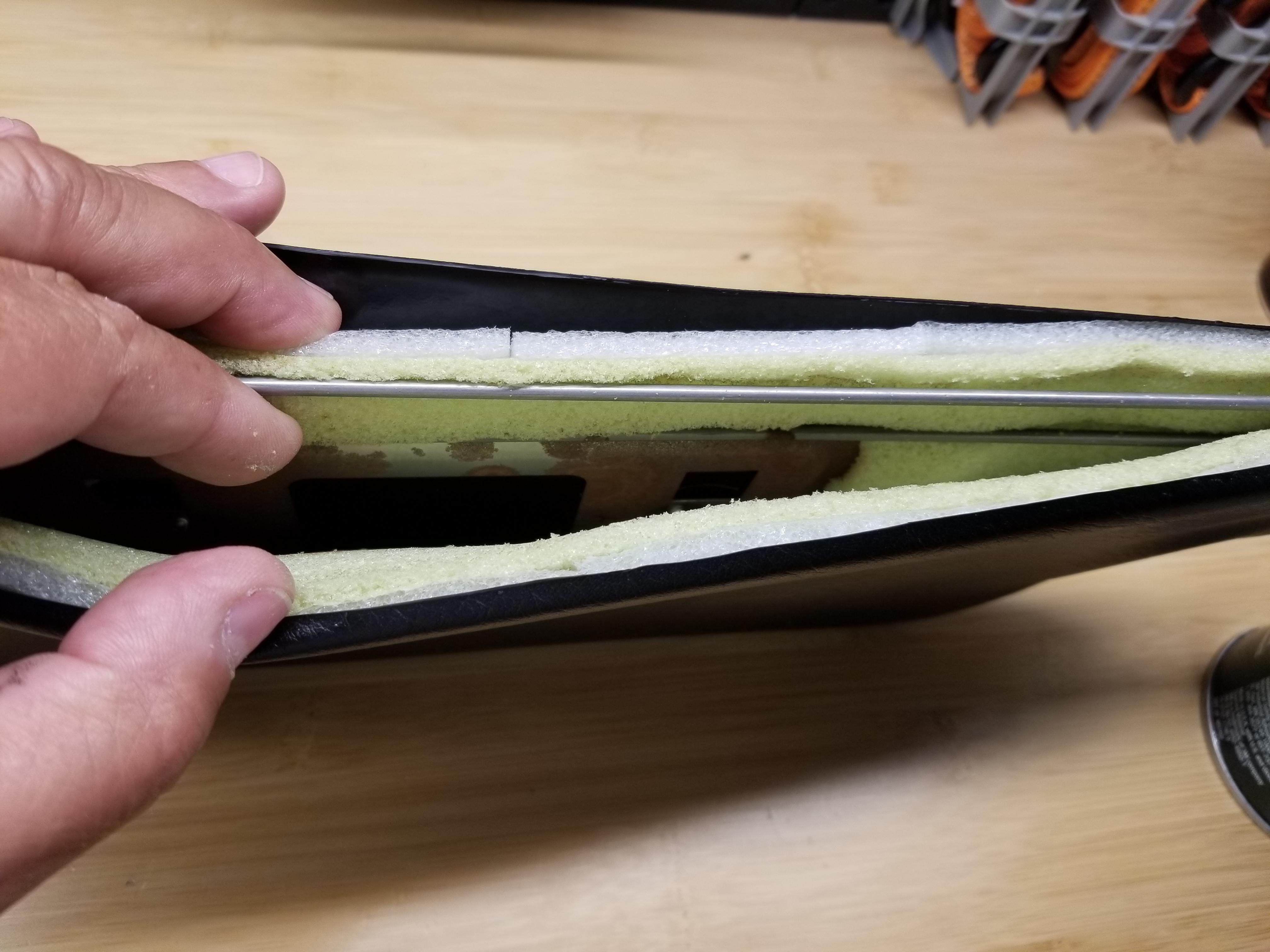
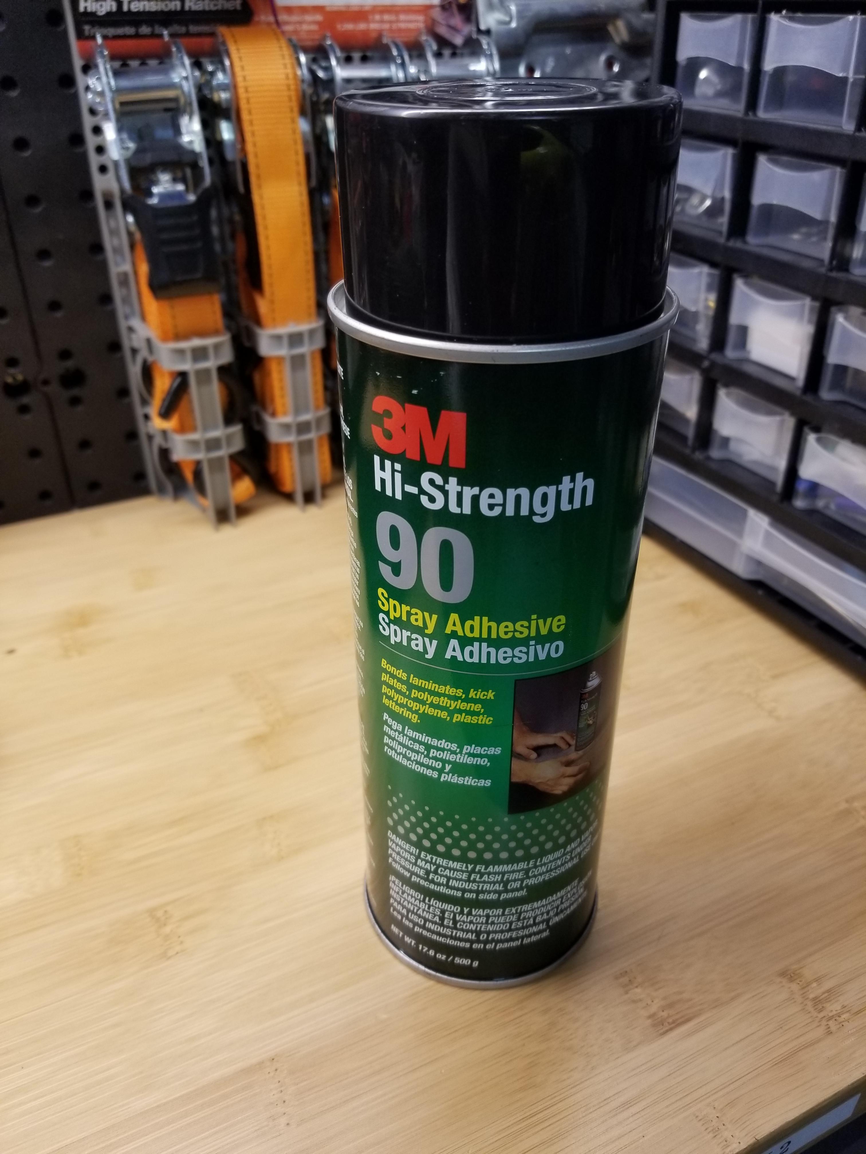
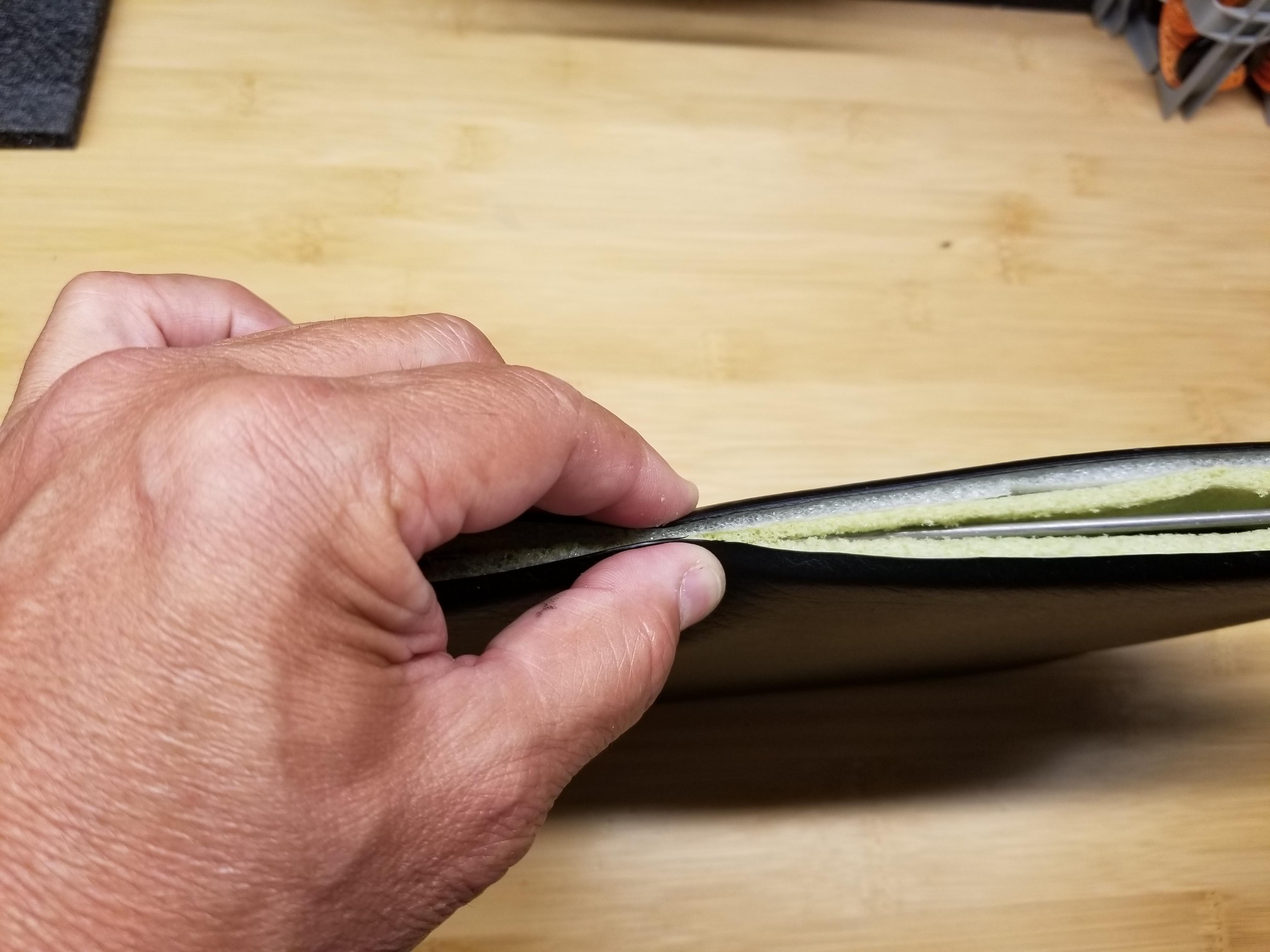
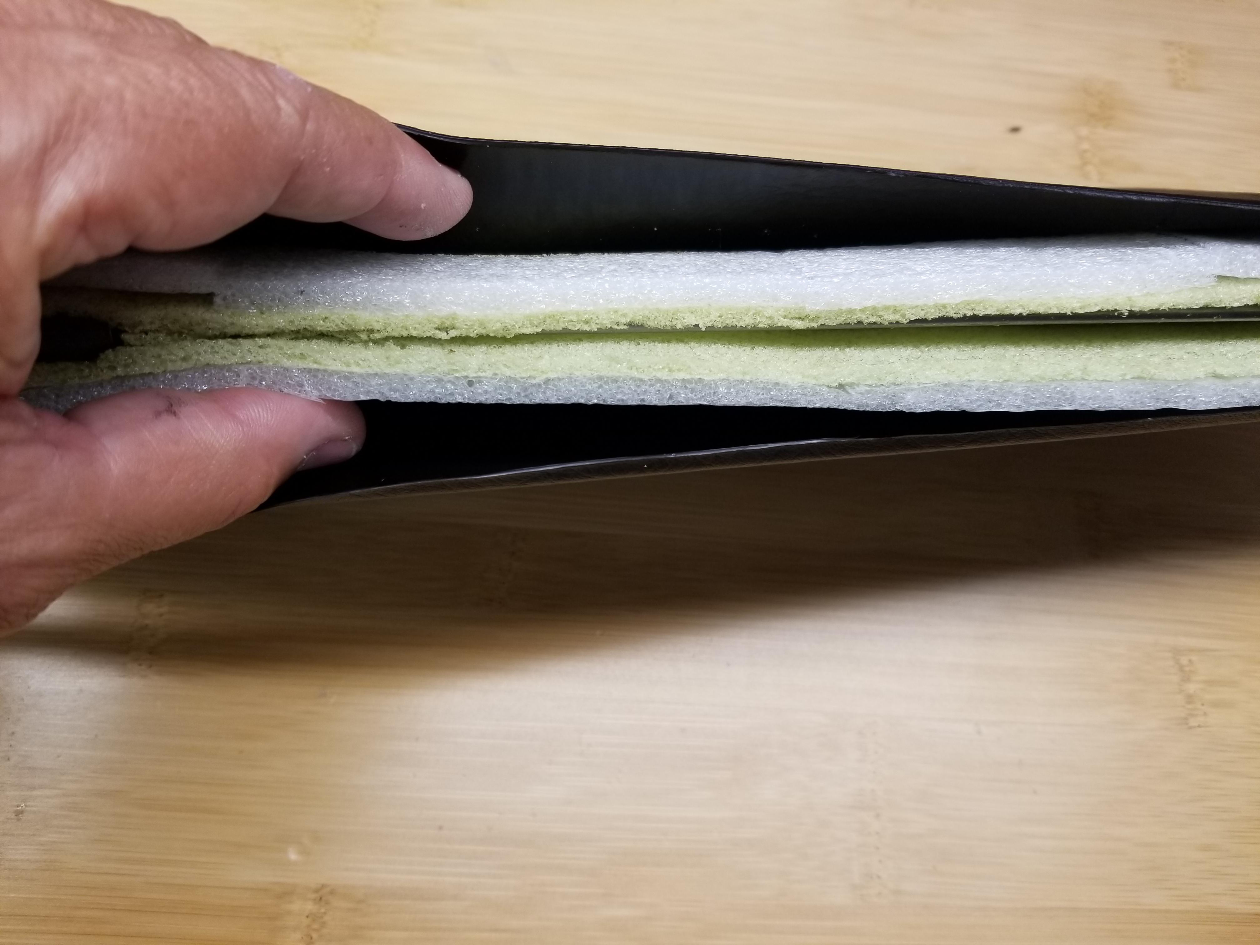
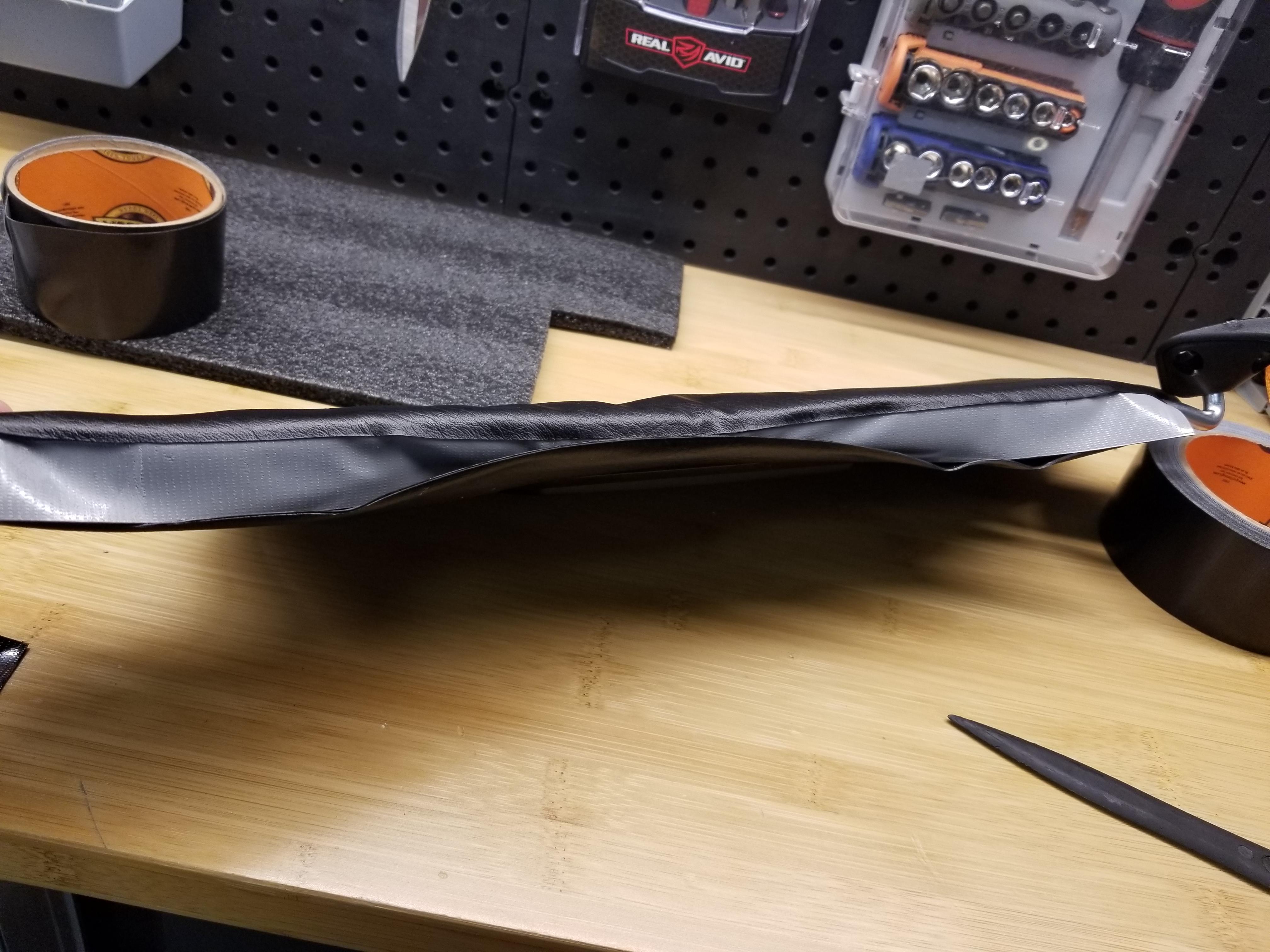
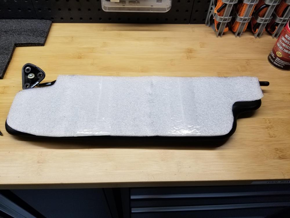
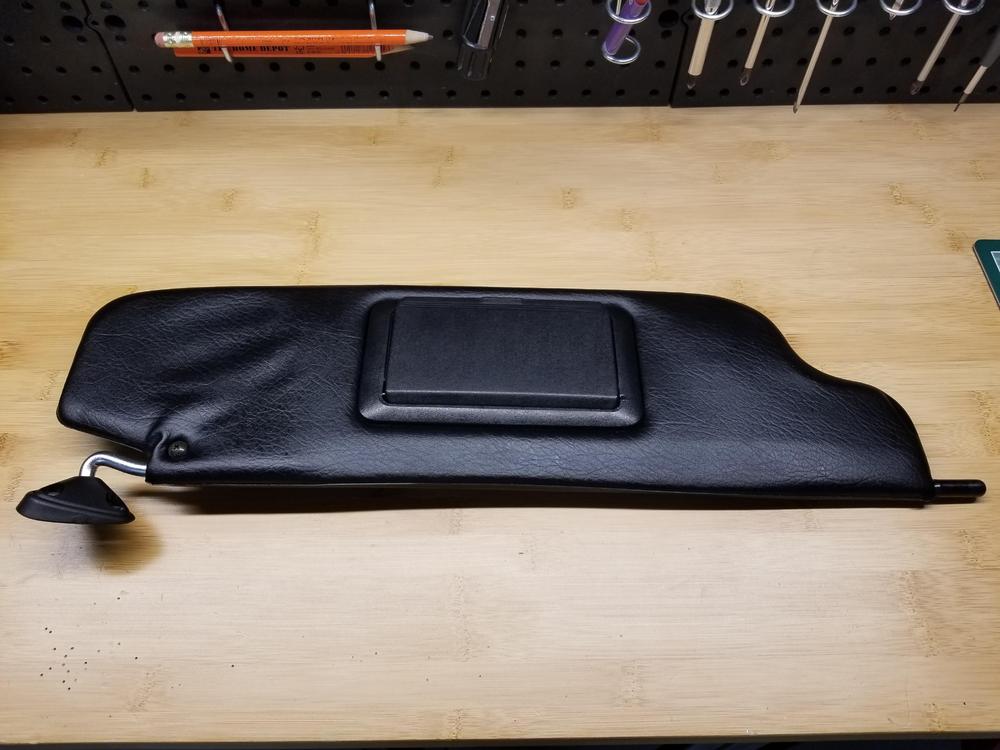
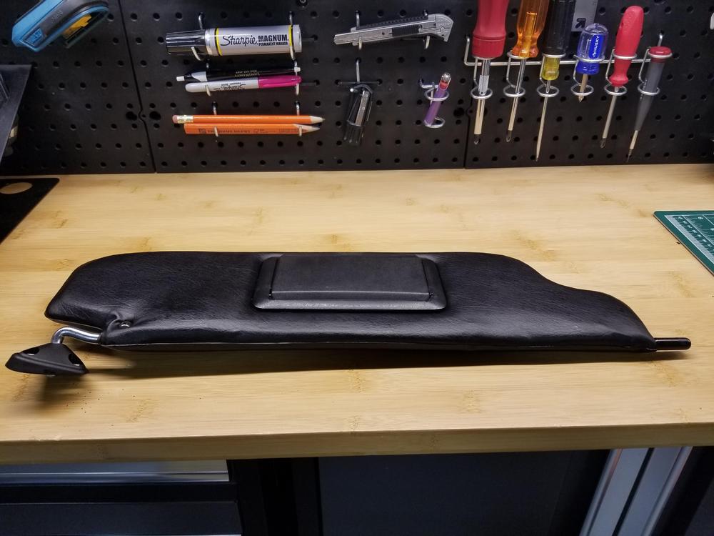
1 pointAfter looking at my original "saggy" sunvisors for a few years (and with lots of "sheltering at home" time) I decided to try a "fix". The vynil skins themselves are in great shape but it seemed as if the internal stuffing had deteriorated over 40 odd years and there were wrinkles here and there on the visors. I didn't want to change the original vynil for leather (visor repair kits on the market) so I decided to cut them open along the forwardmost seam with a fine scalpel blade, staying on one side of the seam so I could later close the seam almost invisibly. To my surprise the foam layer inside was pretty intact and the cause of the wrinkles on the outside was just loose, saggy vynil. I cut out a filler panel for each side out of closed cell foam, 2.5mm thick and carefully fitted and glued it to the existing foam with 3M spray glue. Closing the seam again was tricky but all I could come up with was using a strip of Gorilla tape (that stuff really sticks). I placed half the strip along the inside of the top half of the vynil and slowly pulled the bottom half over the exposed tape until a precise closure was achieved. The result is a nice firm visor with an almost invisible seam. See pics below. PS: I've only done the passenger side (which has the vanity mirror and is a little trickier) because I ran out of the foam. I will do the driver side once I get the foam and will post any details that I might change for improvement. Original "saggy" visors (I know, they're way better than most!!) New foam filler (white) fitted and glued to each side of the original green foam: Trim the foam edges so approximating the vinyl edges can be achieved with just a little stretch: Gorilla tape on the inside of the top half and then bringing the bottom half of the vynil over the bottom half of the tape until the edges are precisely closed (start in the middle): Final result:


 1 point
 -
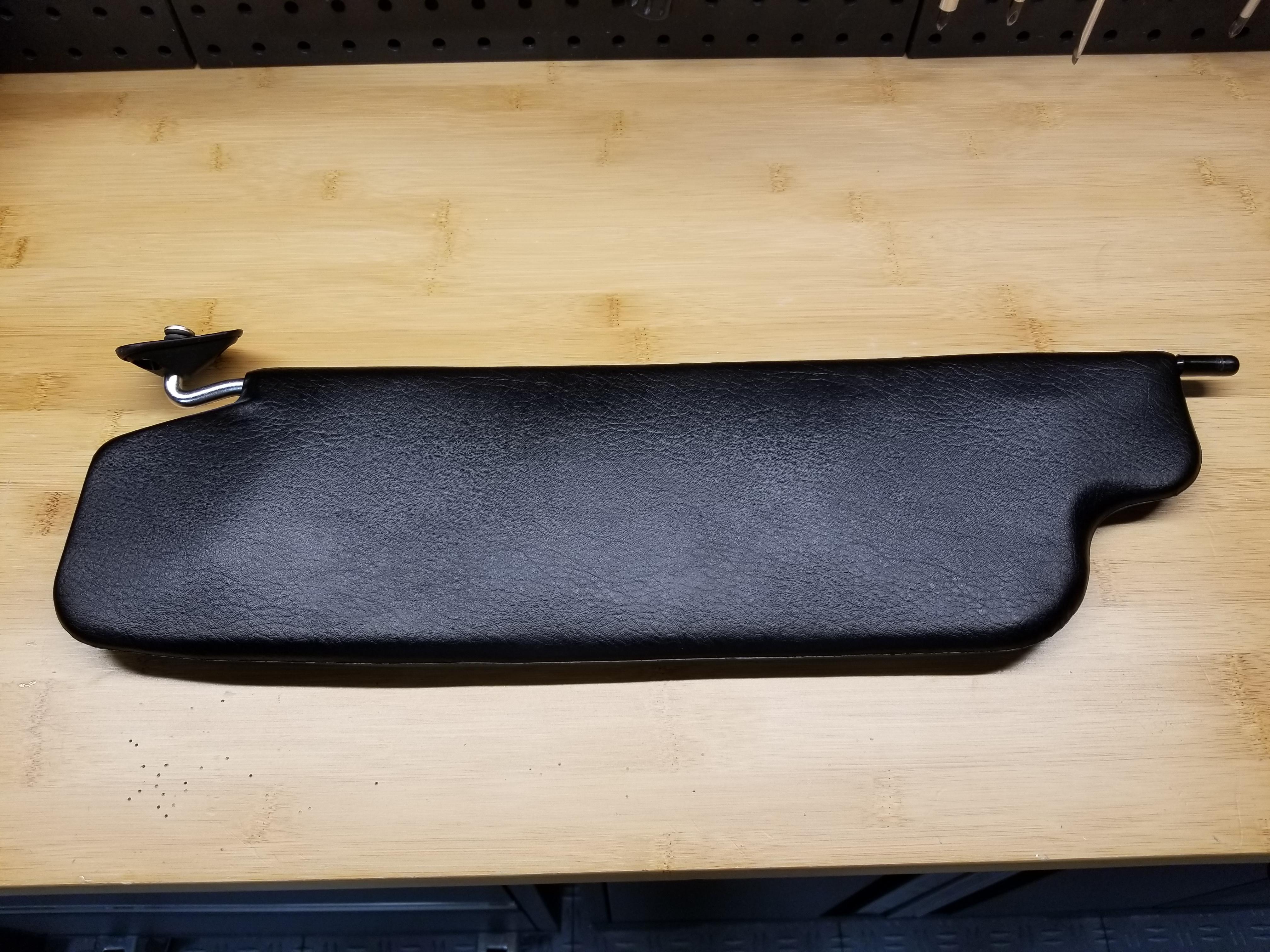
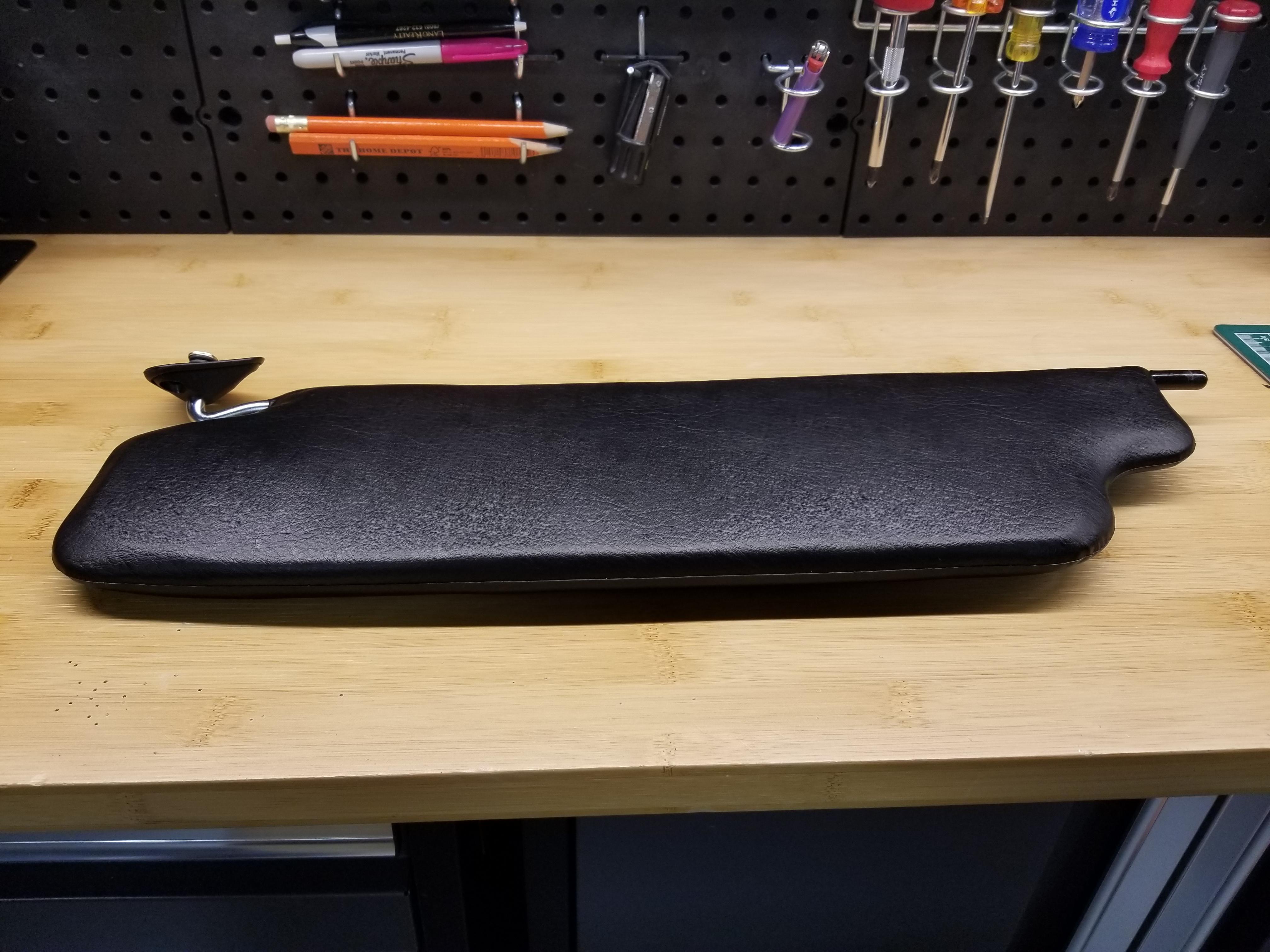
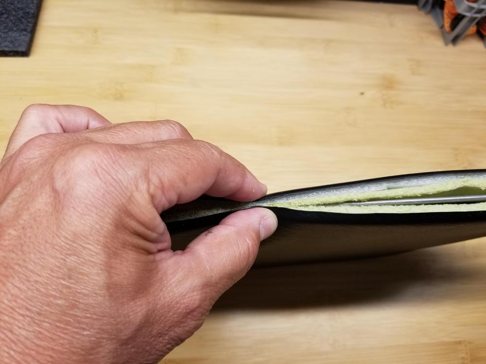
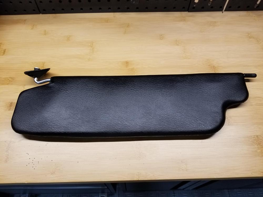
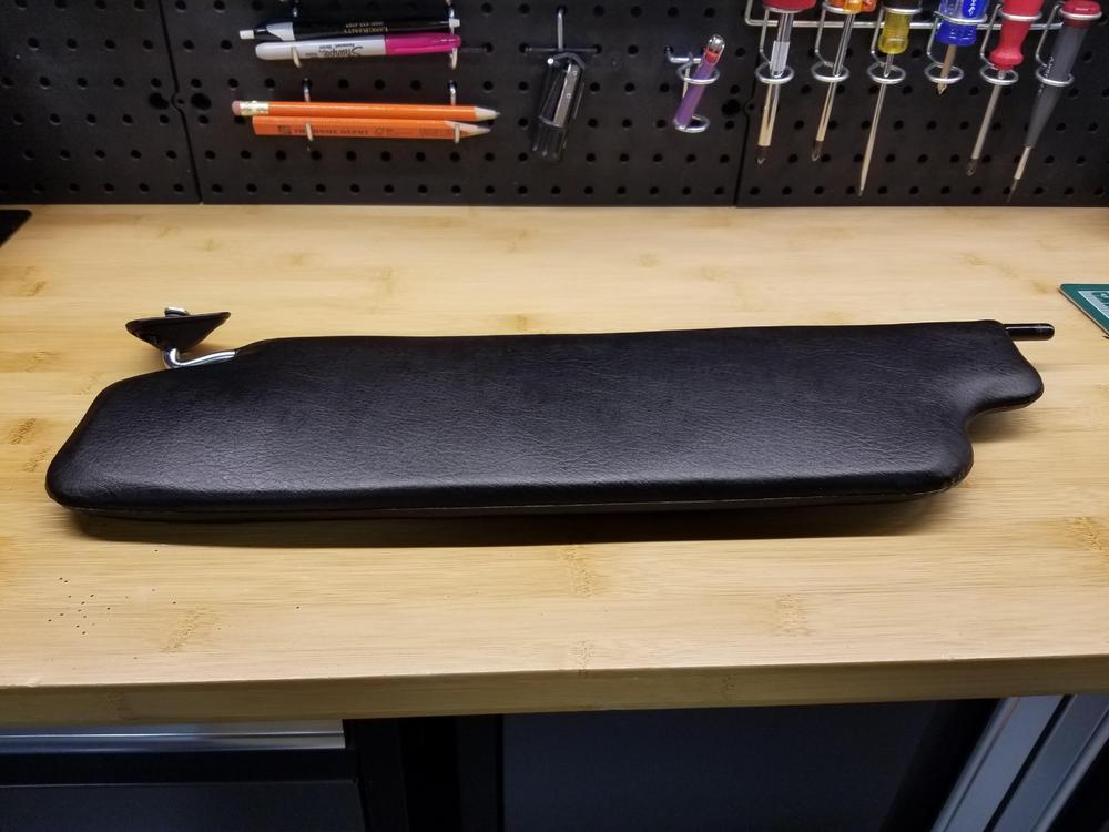
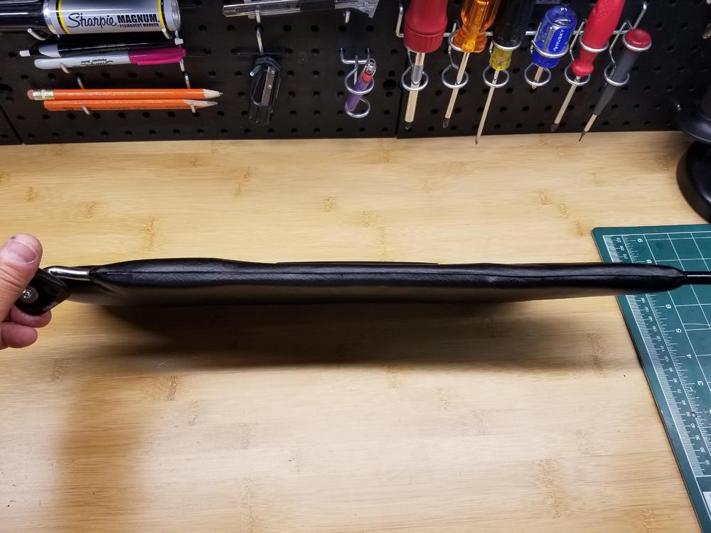
1 pointNot being satisfied with the "plump" look that resulted from my first attempt, I decided to be more radical and opened the visors again, took out all the foam I had added and all the factory green foam pads as well. I started with the now totally empty visor skins and prepared a "sandwich" consisting of a single piece of black 10mm thick high density foam precisely cut to shape, covered with a single layer of 2mm sheet of the same foam on each side. I beveled the edges a bit before reinserting into the visor skins. Closed up the same way as before. I'm super satisfied with the much improved flatness and stock appearance. Sent from my SM-N950U using Tapatalk1 point